EP3108286B1 - Display device - Google Patents
Display device Download PDFInfo
- Publication number
- EP3108286B1 EP3108286B1 EP15705502.1A EP15705502A EP3108286B1 EP 3108286 B1 EP3108286 B1 EP 3108286B1 EP 15705502 A EP15705502 A EP 15705502A EP 3108286 B1 EP3108286 B1 EP 3108286B1
- Authority
- EP
- European Patent Office
- Prior art keywords
- luminous
- display device
- light
- area
- areas
- Prior art date
- Legal status (The legal status is an assumption and is not a legal conclusion. Google has not performed a legal analysis and makes no representation as to the accuracy of the status listed.)
- Active
Links
- 230000003287 optical effect Effects 0.000 claims description 66
- 238000007493 shaping process Methods 0.000 claims description 63
- 239000000463 material Substances 0.000 claims description 34
- 239000000758 substrate Substances 0.000 claims description 24
- 239000003086 colorant Substances 0.000 claims description 10
- 239000012141 concentrate Substances 0.000 claims description 7
- 238000001514 detection method Methods 0.000 claims description 4
- 238000005286 illumination Methods 0.000 claims 4
- 239000010410 layer Substances 0.000 description 20
- 238000013461 design Methods 0.000 description 14
- OAICVXFJPJFONN-UHFFFAOYSA-N Phosphorus Chemical compound [P] OAICVXFJPJFONN-UHFFFAOYSA-N 0.000 description 12
- 230000008901 benefit Effects 0.000 description 9
- 239000002096 quantum dot Substances 0.000 description 9
- 230000005484 gravity Effects 0.000 description 8
- 230000012447 hatching Effects 0.000 description 8
- 238000003384 imaging method Methods 0.000 description 8
- 239000000203 mixture Substances 0.000 description 7
- 150000001875 compounds Chemical class 0.000 description 6
- 230000000694 effects Effects 0.000 description 6
- 238000000034 method Methods 0.000 description 6
- 239000006117 anti-reflective coating Substances 0.000 description 5
- 238000005259 measurement Methods 0.000 description 5
- 230000008569 process Effects 0.000 description 5
- 230000005855 radiation Effects 0.000 description 5
- 230000004888 barrier function Effects 0.000 description 4
- 210000004027 cell Anatomy 0.000 description 4
- 239000011521 glass Substances 0.000 description 4
- 238000004519 manufacturing process Methods 0.000 description 4
- 239000012528 membrane Substances 0.000 description 4
- 239000003990 capacitor Substances 0.000 description 3
- 230000002349 favourable effect Effects 0.000 description 3
- 239000000945 filler Substances 0.000 description 3
- 239000003365 glass fiber Substances 0.000 description 3
- 238000000265 homogenisation Methods 0.000 description 3
- 230000005693 optoelectronics Effects 0.000 description 3
- 230000011514 reflex Effects 0.000 description 3
- 239000004065 semiconductor Substances 0.000 description 3
- 238000010146 3D printing Methods 0.000 description 2
- PLXMOAALOJOTIY-FPTXNFDTSA-N Aesculin Natural products OC[C@@H]1[C@@H](O)[C@H](O)[C@@H](O)[C@H](O)[C@H]1Oc2cc3C=CC(=O)Oc3cc2O PLXMOAALOJOTIY-FPTXNFDTSA-N 0.000 description 2
- 241000238631 Hexapoda Species 0.000 description 2
- 238000010521 absorption reaction Methods 0.000 description 2
- 230000003667 anti-reflective effect Effects 0.000 description 2
- 239000002800 charge carrier Substances 0.000 description 2
- 239000013078 crystal Substances 0.000 description 2
- 238000009792 diffusion process Methods 0.000 description 2
- 238000010894 electron beam technology Methods 0.000 description 2
- 238000005265 energy consumption Methods 0.000 description 2
- 230000004438 eyesight Effects 0.000 description 2
- 238000009434 installation Methods 0.000 description 2
- 239000012044 organic layer Substances 0.000 description 2
- 239000002245 particle Substances 0.000 description 2
- 230000009467 reduction Effects 0.000 description 2
- 238000000926 separation method Methods 0.000 description 2
- 239000007787 solid Substances 0.000 description 2
- 125000006850 spacer group Chemical group 0.000 description 2
- 230000002123 temporal effect Effects 0.000 description 2
- 238000012935 Averaging Methods 0.000 description 1
- 229910000530 Gallium indium arsenide Inorganic materials 0.000 description 1
- 230000005678 Seebeck effect Effects 0.000 description 1
- BQCADISMDOOEFD-UHFFFAOYSA-N Silver Chemical compound [Ag] BQCADISMDOOEFD-UHFFFAOYSA-N 0.000 description 1
- 230000004308 accommodation Effects 0.000 description 1
- 239000000654 additive Substances 0.000 description 1
- 230000000996 additive effect Effects 0.000 description 1
- 238000013459 approach Methods 0.000 description 1
- 238000000149 argon plasma sintering Methods 0.000 description 1
- 230000015572 biosynthetic process Effects 0.000 description 1
- 238000009530 blood pressure measurement Methods 0.000 description 1
- UHYPYGJEEGLRJD-UHFFFAOYSA-N cadmium(2+);selenium(2-) Chemical compound [Se-2].[Cd+2] UHYPYGJEEGLRJD-UHFFFAOYSA-N 0.000 description 1
- 238000005266 casting Methods 0.000 description 1
- 230000008859 change Effects 0.000 description 1
- 239000011248 coating agent Substances 0.000 description 1
- 238000000576 coating method Methods 0.000 description 1
- 229920001940 conductive polymer Polymers 0.000 description 1
- 238000010276 construction Methods 0.000 description 1
- 230000007547 defect Effects 0.000 description 1
- 230000001419 dependent effect Effects 0.000 description 1
- 230000001066 destructive effect Effects 0.000 description 1
- 230000004069 differentiation Effects 0.000 description 1
- 238000005516 engineering process Methods 0.000 description 1
- 238000001914 filtration Methods 0.000 description 1
- 230000004907 flux Effects 0.000 description 1
- 239000005338 frosted glass Substances 0.000 description 1
- 230000006872 improvement Effects 0.000 description 1
- 238000001459 lithography Methods 0.000 description 1
- 229910044991 metal oxide Inorganic materials 0.000 description 1
- 150000004706 metal oxides Chemical class 0.000 description 1
- 239000004005 microsphere Substances 0.000 description 1
- 239000002105 nanoparticle Substances 0.000 description 1
- 230000007935 neutral effect Effects 0.000 description 1
- 229910052698 phosphorus Inorganic materials 0.000 description 1
- 239000011574 phosphorus Substances 0.000 description 1
- 239000004038 photonic crystal Substances 0.000 description 1
- 210000004180 plasmocyte Anatomy 0.000 description 1
- 239000004033 plastic Substances 0.000 description 1
- 230000010287 polarization Effects 0.000 description 1
- 229920000642 polymer Polymers 0.000 description 1
- 238000007639 printing Methods 0.000 description 1
- 239000010453 quartz Substances 0.000 description 1
- 238000001454 recorded image Methods 0.000 description 1
- 238000007789 sealing Methods 0.000 description 1
- VYPSYNLAJGMNEJ-UHFFFAOYSA-N silicon dioxide Inorganic materials O=[Si]=O VYPSYNLAJGMNEJ-UHFFFAOYSA-N 0.000 description 1
- 229910052709 silver Inorganic materials 0.000 description 1
- 239000004332 silver Substances 0.000 description 1
- 230000002269 spontaneous effect Effects 0.000 description 1
- 238000012549 training Methods 0.000 description 1
- 239000012780 transparent material Substances 0.000 description 1
- 230000004304 visual acuity Effects 0.000 description 1
- 230000000007 visual effect Effects 0.000 description 1
Images


Classifications
-
- G—PHYSICS
- G02—OPTICS
- G02B—OPTICAL ELEMENTS, SYSTEMS OR APPARATUS
- G02B26/00—Optical devices or arrangements for the control of light using movable or deformable optical elements
- G02B26/02—Optical devices or arrangements for the control of light using movable or deformable optical elements for controlling the intensity of light
-
- G—PHYSICS
- G02—OPTICS
- G02B—OPTICAL ELEMENTS, SYSTEMS OR APPARATUS
- G02B6/00—Light guides; Structural details of arrangements comprising light guides and other optical elements, e.g. couplings
- G02B6/0001—Light guides; Structural details of arrangements comprising light guides and other optical elements, e.g. couplings specially adapted for lighting devices or systems
- G02B6/0005—Light guides; Structural details of arrangements comprising light guides and other optical elements, e.g. couplings specially adapted for lighting devices or systems the light guides being of the fibre type
- G02B6/0006—Coupling light into the fibre
-
- G—PHYSICS
- G02—OPTICS
- G02F—OPTICAL DEVICES OR ARRANGEMENTS FOR THE CONTROL OF LIGHT BY MODIFICATION OF THE OPTICAL PROPERTIES OF THE MEDIA OF THE ELEMENTS INVOLVED THEREIN; NON-LINEAR OPTICS; FREQUENCY-CHANGING OF LIGHT; OPTICAL LOGIC ELEMENTS; OPTICAL ANALOGUE/DIGITAL CONVERTERS
- G02F1/00—Devices or arrangements for the control of the intensity, colour, phase, polarisation or direction of light arriving from an independent light source, e.g. switching, gating or modulating; Non-linear optics
- G02F1/01—Devices or arrangements for the control of the intensity, colour, phase, polarisation or direction of light arriving from an independent light source, e.g. switching, gating or modulating; Non-linear optics for the control of the intensity, phase, polarisation or colour
- G02F1/13—Devices or arrangements for the control of the intensity, colour, phase, polarisation or direction of light arriving from an independent light source, e.g. switching, gating or modulating; Non-linear optics for the control of the intensity, phase, polarisation or colour based on liquid crystals, e.g. single liquid crystal display cells
- G02F1/133—Constructional arrangements; Operation of liquid crystal cells; Circuit arrangements
- G02F1/1333—Constructional arrangements; Manufacturing methods
- G02F1/1335—Structural association of cells with optical devices, e.g. polarisers or reflectors
- G02F1/1336—Illuminating devices
- G02F1/133602—Direct backlight
- G02F1/133603—Direct backlight with LEDs
-
- H—ELECTRICITY
- H10—SEMICONDUCTOR DEVICES; ELECTRIC SOLID-STATE DEVICES NOT OTHERWISE PROVIDED FOR
- H10K—ORGANIC ELECTRIC SOLID-STATE DEVICES
- H10K50/00—Organic light-emitting devices
-
- G—PHYSICS
- G02—OPTICS
- G02F—OPTICAL DEVICES OR ARRANGEMENTS FOR THE CONTROL OF LIGHT BY MODIFICATION OF THE OPTICAL PROPERTIES OF THE MEDIA OF THE ELEMENTS INVOLVED THEREIN; NON-LINEAR OPTICS; FREQUENCY-CHANGING OF LIGHT; OPTICAL LOGIC ELEMENTS; OPTICAL ANALOGUE/DIGITAL CONVERTERS
- G02F1/00—Devices or arrangements for the control of the intensity, colour, phase, polarisation or direction of light arriving from an independent light source, e.g. switching, gating or modulating; Non-linear optics
- G02F1/01—Devices or arrangements for the control of the intensity, colour, phase, polarisation or direction of light arriving from an independent light source, e.g. switching, gating or modulating; Non-linear optics for the control of the intensity, phase, polarisation or colour
- G02F1/13—Devices or arrangements for the control of the intensity, colour, phase, polarisation or direction of light arriving from an independent light source, e.g. switching, gating or modulating; Non-linear optics for the control of the intensity, phase, polarisation or colour based on liquid crystals, e.g. single liquid crystal display cells
- G02F1/133—Constructional arrangements; Operation of liquid crystal cells; Circuit arrangements
- G02F1/1333—Constructional arrangements; Manufacturing methods
- G02F1/1335—Structural association of cells with optical devices, e.g. polarisers or reflectors
- G02F1/133509—Filters, e.g. light shielding masks
- G02F1/133512—Light shielding layers, e.g. black matrix
-
- G—PHYSICS
- G02—OPTICS
- G02F—OPTICAL DEVICES OR ARRANGEMENTS FOR THE CONTROL OF LIGHT BY MODIFICATION OF THE OPTICAL PROPERTIES OF THE MEDIA OF THE ELEMENTS INVOLVED THEREIN; NON-LINEAR OPTICS; FREQUENCY-CHANGING OF LIGHT; OPTICAL LOGIC ELEMENTS; OPTICAL ANALOGUE/DIGITAL CONVERTERS
- G02F1/00—Devices or arrangements for the control of the intensity, colour, phase, polarisation or direction of light arriving from an independent light source, e.g. switching, gating or modulating; Non-linear optics
- G02F1/01—Devices or arrangements for the control of the intensity, colour, phase, polarisation or direction of light arriving from an independent light source, e.g. switching, gating or modulating; Non-linear optics for the control of the intensity, phase, polarisation or colour
- G02F1/13—Devices or arrangements for the control of the intensity, colour, phase, polarisation or direction of light arriving from an independent light source, e.g. switching, gating or modulating; Non-linear optics for the control of the intensity, phase, polarisation or colour based on liquid crystals, e.g. single liquid crystal display cells
- G02F1/133—Constructional arrangements; Operation of liquid crystal cells; Circuit arrangements
- G02F1/1333—Constructional arrangements; Manufacturing methods
- G02F1/1335—Structural association of cells with optical devices, e.g. polarisers or reflectors
- G02F1/13356—Structural association of cells with optical devices, e.g. polarisers or reflectors characterised by the placement of the optical elements
- G02F1/133562—Structural association of cells with optical devices, e.g. polarisers or reflectors characterised by the placement of the optical elements on the viewer side
-
- H—ELECTRICITY
- H10—SEMICONDUCTOR DEVICES; ELECTRIC SOLID-STATE DEVICES NOT OTHERWISE PROVIDED FOR
- H10K—ORGANIC ELECTRIC SOLID-STATE DEVICES
- H10K50/00—Organic light-emitting devices
- H10K50/80—Constructional details
- H10K50/85—Arrangements for extracting light from the devices
- H10K50/854—Arrangements for extracting light from the devices comprising scattering means
-
- H—ELECTRICITY
- H10—SEMICONDUCTOR DEVICES; ELECTRIC SOLID-STATE DEVICES NOT OTHERWISE PROVIDED FOR
- H10K—ORGANIC ELECTRIC SOLID-STATE DEVICES
- H10K59/00—Integrated devices, or assemblies of multiple devices, comprising at least one organic light-emitting element covered by group H10K50/00
- H10K59/80—Constructional details
- H10K59/875—Arrangements for extracting light from the devices
- H10K59/877—Arrangements for extracting light from the devices comprising scattering means
Definitions
- the invention relates to a color display device with a display area with several pixels.
- display devices are known in the prior art, for example as LCD display devices or OLED display devices.
- the disadvantage of such display devices is the limited contrast range that these display devices have.
- the US 2008/0024470 shows an invisible, translucent display system, in an opaque material.
- Substantially invisible, tapered, translucent holes are penetrated in a translucent pattern through at least a portion of the light-resistant material using a laser beam having a focal length smaller than the smallest diameter of the cone-shaped holes.
- the main target is an application as LED indicators, e.g. for battery or stand-by light signals, which are to be invisibly integrated into a material, whereby the holes themselves should be very small and the distance between the holes depends on the resolving power of the adapted to the viewer.
- the US 2007/085471 relates to an organic light-emitting diode (OLED) device comprising a first electrode and a second electrode with one or more organic layers formed therebetween, at least one organic layer being light-emitting, the first and second electrodes defining one or more light-emitting regions, and wherein at least one of the first and second electrodes includes reflective and transparent portions in the light-emitting region.
- OLED organic light-emitting diode
- the object of the present invention is to improve color display devices of the first type mentioned, i.e. display device with a display area with several pixels, e.g. LCD or OLED display devices, in particular to improve the display quality and / or the visual impression of such a display and / or to make the display device more energy efficient and/or to expand the display device for further applications.
- the task is solved by a color display device with a display area consisting of non-luminous areas and luminous areas, the centers of gravity of adjacent luminous areas having mutual distances that are smaller than the resolution of a viewer and preferably the proportion of non-illuminating areas in the total display area is more than 70%.
- Luminous area maximization results in exactly the opposite reduction in the proportion of luminous areas in the display area and an enlargement of the non-illuminating areas between the luminous areas.
- dark areas can actually remain dark because they are relatively much larger than the luminous areas, even more so with a proportion of non-luminous areas of, for example, more than 95% (a preferred feature of this invention, see below ), and are less light-reflecting, which is particularly advantageous in darker parts of the image and/or in strong ambient light.
- a color display device or display is understood to mean a device which is set up to display preferably digital or digitized images, text, graphics or video, each of which is composed of individual pixels.
- a handheld device e.g. mobile device/smartphone, bracelet/pocket watch, pocket media player, tablet, etc.
- a conventional computer laptop, desktop, etc.
- a television or an advertising/information display board e.g. in Subways, sports stadiums or department stores, on house walls, etc.
- the display area is a surface of the display device facing the viewer, within which the individual pixels are arranged.
- the display area is preferably delimited by an (imaginary) line which runs along the outermost pixels, preferably along the outermost luminous areas of the display device.
- a frame generally runs around the display surface, which, for example, ensures mechanical stability, but the thinner it is, the more advantageous it is for the design, for example.
- a luminous surface is understood to be a surface from which light rays emanate to the viewer when the mode is switched on. The light rays can either be generated or emitted directly in the surface (e.g.
- a luminous surface can be a hole or a Be a hole, which offers light or light rays an opening from which the light rays reach the viewer.
- the surface consists partially or entirely of a solid body that is at least partially or to a certain degree or completely transparent or runs partially or entirely through it.
- the luminous areas are those areas of the display device which represent the subpixels and emit the light to the viewer when the subpixels light up.
- the shape of the light surface is arbitrary, preferably square or round.
- at least one luminous surface shape is identically present in uniform repetition.
- a luminous area is preferably assigned to a pixel.
- a pixel or a subpixel for example RGB subpixel, has several luminous areas. In this way, the light intensity and the color representation can be realized in a more fine-grained manner.
- a pixel has at least two luminous surfaces, so that light emission in several spatial directions, preferably in opposite directions, can be realized. In this way, e.g. B.
- a display area of a display device makes several display areas available to the viewer, so that, for example, a tablet computer has a display on each side or on the top and bottom in order to simplify handling even further.
- a luminous surface is understood to mean a surface from which light rays emanate to the viewer when the mode is switched on.
- a non-illuminating surface means areas that are present between the luminous surfaces and which do not glow on their own or are backlit.
- Preferably one or all non-luminous surfaces are at least 90% opaque.
- the center of gravity of a luminous surface is the geometric center of gravity or centroid of the surface, which mathematically corresponds to the averaging of all points within the surface.
- Distances that are smaller than the resolution of a viewer are preferably such that the pixels or luminous surfaces are arranged so close together that a viewer, whose eyes are preferably at a distance from the display device, which is appropriate for the specific type of display device As is common when using the display device, two neighboring pixels or luminous areas can no longer be distinguished from one another.
- the distances that are smaller than the resolution of the viewer such distances that appear to the viewer at an angle of a maximum of two angular minutes.
- the pixels or illuminated areas are no longer distinguishable for the majority of viewers, since in unfavorable cases the human resolution power corresponds to around 2 angular minutes.
- the distances appear to the observer at a maximum angle of 1 angular minute, particularly preferably 0.5 angular minute, particularly preferably 0.25 angular minute.
- the pixels or illuminated areas are no longer distinguishable for almost all human observers. The smaller the maximum angle, the fewer observers there are whose vision is sufficient to distinguish between two pixels or illuminated areas.
- the viewer's eyes or eyes are at a distance from the display surface, which is usual for the specific type of display device when using the display device.
- the distance is 5 cm to 1.20 m, preferably 15 cm to 60 cm for displays of handheld devices (mobile phones, watches, tablet computers), 25 cm to 2 m, preferably 40 cm to 1 m for displays of desktop devices.
- Computers 1 m to 7 m preferably 2 m to 5 m for televisions and/or 2 m to 100 m, preferably 5 m to more than 100 m for advertising/information display boards.
- the distances that are smaller than the viewer's resolution, less than 1 mm which is, for example, a distance in the case of a television in which the user can no longer see the individual pixels or luminous areas at the usual viewing distance (> 2m). can distinguish from each other.
- the display device is a desktop computer with a minimum user distance (based on the eye) of 50 cm.
- the pixels or luminous areas of the display device are spaced apart from one another for a safety buffer, thus for at least 70 % of users are able to achieve a particularly high-quality display during normal use of the display device, since individual illuminated areas cannot be distinguished for them.
- the result is a resolution of the display device of 317 DPI, preferably 320 DPI with a security buffer.
- the distances that are smaller than the resolution of the viewer are a maximum of 190 ⁇ m, preferably a maximum of 80 ⁇ m, particularly preferably a maximum of 50 ⁇ m. This ensures that, even if the viewer comes closer to the display area than usual, he cannot distinguish individual pixels or illuminated areas from one another can. Depending on the resolution and accommodation ability of the individual viewer, it does not matter how close the individual viewer comes to the display device, because even if he makes optimal use of his vision and approaches the closest focusing limit of his eye, he cannot distinguish the individual pixels or luminous areas from one another.
- the extent of one, preferably each, luminous surface is preferably at most 70 ⁇ m, preferably at most 25 ⁇ m, particularly preferably at most 10 ⁇ m or even at most 5 ⁇ m. This ensures that the viewer cannot see illuminated surfaces with the naked eye (when switched off) and the contrast appears higher.
- the extent is preferably an extent, preferably the maximum extent, of a luminous surface parallel to the display surface. Particularly preferably, the extent is less than or equal to the wavelength of the visible and/or the light to be transmitted. It is, for example, at most 2 ⁇ m, preferably at most 1 ⁇ m or at most 0.5 ⁇ m. As a result, the exit angle of the light emanating from the luminous surface is larger, particularly due to the Rayleigh criterion.
- the proportion of the non-illuminating areas in the total display area is preferably the proportion of the sum of all the areas of the non-illuminating areas in the area of the total display area. It is preferably inverse to the proportion of luminous areas on the display area, i.e. the proportion of non-illuminating areas and the proportion of luminous areas on the entire display area are preferably 100%.
- the proportion of luminous areas in the display area is preferably the proportion of the sum of all areas of the luminous areas in the entire display area.
- the non-luminous areas of the display area have so far usually resulted from wiring for the control of LCD cells and the prior art strives to minimize these remaining areas as much as possible so that the luminous areas receive as much space as possible. Therefore, in a preferred display device, it is advantageous if at least one functional element is arranged in the space between the luminous surfaces in order to use the space between the luminous surfaces. Additional functions can thus be integrated using the at least one functional element.
- the at least one functional element can have a solar element and/or a sensor.
- a sensor can be, for example, a temperature sensor, a distance sensor, a pressure sensor, a gas sensor or an image sensor.
- the proportion of non-illuminating areas in the total display area is preferably greater than 80%, preferably greater than 90%, particularly preferably greater than 95%, very particularly preferably greater than 98% and finally even more preferably at least 99%.
- the proportion of the luminous areas in the entire display area is preferably at most 20%, preferably at most 10%, particularly preferably at most 5%, very particularly preferably at most 2% and finally even more preferably at most 1%.
- the color display device has at least one functional element.
- the display device can be expanded to include further functions.
- the at least one functional element can have a solar element for converting solar energy into electrical energy. This allows the display device to be supplied with energy. Thus, part or all of the energy required for the display device can be obtained from solar energy, whereby e.g. B. a battery of the display device can be relieved or even saved.
- the at least one functional element can have a sensor, preferably a two-dimensional and/or three-dimensional sensor. Furthermore, it is preferred if the at least one functional element has an image sensor or a touch-sensitive sensor, in particular a piezo element.
- a sensor can expand the display device to include a further application, e.g. B. about the detection of input by a user. For example, user input can be detected using a temperature sensor, a distance sensor, a pressure sensor, a gas sensor or an image sensor.
- the temperature sensor has a heat sensor with a quartz oscillator or a thermocouple that converts a temperature difference into an electrical voltage using the Seebeck effect. It is also possible for the temperature sensor to have a pyroelectric material that changes the charge carrier density on the surface in the event of temperature fluctuations by changing the spontaneous polarization, or a mechanically operating temperature switch, e.g. B. Bimetal switch, which operates a switch by deforming a bimetal.
- a capacitive sensor has two plate elements that are insulated from each other and form a capacitor, e.g. B. a user's finger represents a dielectric. The dielectric in the capacitor varies its capacity, which can be easily detected by measuring voltage.
- a distance sensor is therefore a touch-sensitive sensor.
- the pressure sensor is piezoresistive or piezoelectric.
- a piezoresistive pressure sensor the pressure to be measured deforms a membrane that has applied electrical resistances. The pressure-dependent deformation of the membrane also deforms resistances diffused onto the membrane, which leads to the formation of an electrical voltage, which can also be measured in a simple manner.
- the pressure being measured causes charge separation in a crystal, which creates an electrical voltage. The pressure shifts charges inside the crystal, forming an electric charge on the surface proportional to the force. If the sensor is to be used for pressure measurement, the pressure must first be converted proportionally into a force via a membrane.
- a pressure sensor is a touch-sensitive sensor, with the piezoresistive and piezoelectric pressure sensors having a piezo element. It is also conceivable to use the pressure sensor to generate a force and thus ensure haptic feedback in the form of a vibration, for example. B. the piezo element of the pressure sensor is activated and deactivated in cycles.
- the sensor of the at least one functional element is a gas sensor, which preferably works according to a resistive principle, in which the gas or gas mixture to be measured directly influences the conductivity of a gas-sensitive sensor layer. This change in resistance serves as a measurement variable.
- sensors are e.g. B. inorganic metal oxide semiconductors (MOX) or conductive polymer.
- a gas sensor can also work according to the capacitive principle, in which the capacitance of a capacitor is measured, which in turn is influenced by a gas-sensitive dielectric, such as a polymer sensor for measuring humidity.
- the at least one functional element has a two-dimensional or three-dimensional sensor, in particular an image sensor.
- a two-dimensional sensor or two-dimensional image sensor is understood to mean a device for recording two-dimensional images, for which semiconductor-based ones are used Image sensors are used that can record light. This is preferably a so-called CCD sensor or a so-called CMOS sensor.
- a three-dimensional sensor or three-dimensional image sensor has at least two two-dimensional sensors or image sensors that are spaced apart from one another. In this way, a subject can be captured using the principle of stereoscopy in order to convey a spatial impression when displaying two two-dimensionally spaced images.
- the at least one functional element has a beam shaping element and a beam detector device.
- the beam shaping element which is preferably translucent, directs light onto the beam detector device.
- a plenoptic camera also called a light field camera, or a type of compound eye like that of an insect.
- the beam shaping element is fitted into the surface of the display device. This means that a flat surface can be achieved.
- the beam shaping element is a lens of any shape and the beam detector device is an image sensor.
- a plenoptic camera In contrast to a conventional camera, a plenoptic camera not only records the position and intensity of a light beam that hits an image sensor, but also the direction from which the light beam falls. In this way, a so-called light field measurement can be carried out, which e.g. B. can be technically implemented in a specific application using a grid of several microlenses in front of an image sensor.
- a plenoptic camera The advantages of a plenoptic camera are a high depth of field, no waiting for a focusing process and subsequent adjustment of the focal plane of a captured image. Since depth information can also be determined from the image data obtained, a plenoptic camera is also suitable as a three-dimensional camera, with the recorded image data also making it possible to subsequently expand the depth of field.
- the functional element which has a beam shaping element and a beam detector device, to produce a photocopy or an image, for example. B. to make an object.
- an ordinary camera can also be realized with several functional elements.
- a luminous surface and at least one functional element are activated at the same time in order to detect an object by means of reflection and absorption.
- the luminous surface and the at least one functional element adjoin one another. This means that the reflection and absorption of a body or object can be detected easily and efficiently, allowing the surface of the object to be determined according to properties such as: B. Color, brightness and contrast as well as structure is possible. An object can therefore be detected or scanned or copied so that a copy of it can be displayed, in particular via the display device or its luminous surfaces and non-luminous surfaces. It is advantageous if the object is arranged close to, in particular directly to, the display device. The closer the object, the better and more realistically the display device can detect this object using the luminous surfaces and the at least one functional element.
- the temporal resolution can be higher than a standard camera.
- This high temporal resolution is particularly suitable for moving objects, such as. B. Fingers.
- a three-dimensional sensor e.g. B. can be implemented for entering user commands.
- the described at least one functional element can be used, in particular in conjunction with further functional elements, with each functional element preferably having a beam shaping element and a beam detector device.
- the eye artificially reproduced by the display device is advantageously flat, preferably in the plane of the display device.
- three-dimensional touch and proximity sensors can be realized using the at least one functional element implemented as a sensor with a large number of cameras.
- the at least one functional element has an optoelectronic sensor. It is preferred if the at least one functional element has an optoelectronic sensor with a transmitter and receiver. In this way, objects or objects can be detected by the display device with regard to their shape. By arranging several such optoelectronic sensors next to each other, a detection field can be implemented for objects that are positioned in front of the display device. This means that a user's fingers can also be detected, allowing user input to be recorded. Of course you can - As already mentioned - surfaces of objects and their shape can also be recorded.
- At least one non-illuminating surface has at least one functional element.
- the space between two luminous surfaces can therefore be used for at least one functional element.
- a temperature sensor, distance sensor, pressure sensor, gas sensor or image sensor can also be integrated into the display device, whereby the available installation space is used in the best possible way. This means that small devices with a high sensor density and other properties can be created.
- one or more luminous areas are assigned to a pixel and the display area has a large number of such pixels, which are arranged in a repeating pattern, preferably evenly, so that images can be composed from the pixels.
- luminous areas of a pixel have smaller mutual distances than the distances to luminous areas of another pixel.
- a luminous area is preferred, particularly preferably all luminous areas are separated from other luminous areas of other pixels, for example by an area that is not luminous or light-conducting, i.e. by non-luminous areas.
- the display device is monochrome and the pixels are each formed by a single luminous area, or the display device is polychrome and the pixels are each formed by two or more luminous areas, with the luminous areas glowing in different primary colors or the pixels are each formed by one luminous area, which glows polychrome.
- a majority, preferably all, of the non-illuminating surfaces have a reflectance of diffuse reflection of less than 50%.
- the non-illuminating surfaces are advantageously used to positively influence the contrast ratio.
- a decisive advantage here is that, in contrast to conventional display devices, a much larger area is available (namely the entire area of all non-illuminating surfaces) in order to generate a low degree of reflectance, although it is not necessary to ensure that the non-luminous surfaces must be transparent or transmit light and therefore a low degree of reflectance can be achieved more easily and with greater scope (e.g. through the choice of material, surface structure, surface coating, etc.).
- the reflectance of diffuse reflection is preferably less than 25%, particularly preferably less than 10%, very particularly preferably less than 5% and even more preferably less than 1%.
- the background of the luminous surfaces (OLED, LCD, LED, etc.) is provided with a very high degree of reflectance in order to bring as much light as possible to the front (by means of a luminous surface as large as possible).
- This has a negative effect on the contrast in darker areas, especially in strong ambient light, which in turn forces the light intensity to be increased to achieve a good contrast compared to the ambient light, which in turn costs more energy.
- This in turn is a significant disadvantage for portable devices, for example.
- this invention exactly the opposite is aimed for and achieved (even if the background of the minimal luminous surfaces has a very high degree of reflectance).
- a reflectance level of diffuse reflection is preferably measurable as a so-called Light Reflectance Value, LVR (preferably in accordance with the British measurement standard BS8493:2008+A 1:201 0), particularly preferably as an albedo value using an albedometer, preferably a majority, preferably all of the non-luminous ones Areas have an albedo of less than 0.5, preferably less than 0.25, particularly preferably less than 0.10, most preferably less than 0.05 and even more preferably less than 0.01.
- Albedo is preferably the ratio of the radiation flux reaching the observer from a full irradiated surface to that which would reach the observer from a diffusely reflecting, absolutely white disk (a so-called Lambert radiator) of the same size with vertical incidence of light.
- a majority, preferably all, of the non-illuminating surfaces have a reflectance of specular reflection of less than 50%.
- the non-illuminating surfaces are advantageously used to positively influence the contrast ratio.
- readability is increased because uneven mirror images fade across the display image is reduced.
- a decisive advantage here is that, in contrast to conventional display devices, a much larger area is available to generate a low level of reflectance. Is preferred the reflectance of specular reflection is less than 25%, particularly preferably less than 10%, very particularly preferably less than 5% and even more preferably less than 1%.
- the (larger) luminous surfaces are usually provided with glass or glass-like material, and thus the entire display surface has a greater specular reflectance.
- this invention is based on very small luminous areas, so that the display area hardly has any specular reflections, even if the luminous areas are provided with glass or glass-like material.
- a degree of reflection of specular reflection is preferably measurable in GU (gloss unit) using a gloss meter, with preferably a majority, preferably all of the non-luminous surfaces having a gloss in GU of less than 50 GU, preferably less than 25 GU, particularly preferably less than 10 GU , very particularly preferably less than 5 GU and even more preferably less than 1 GU.
- the scale for GU is preferably based on the reference value achieved with a polished, black glass. During calibration, this reference value is preferably set as 100 GU.
- the second reference point on the scale is preferably at 0 GU, the measurement value that is achieved with a perfectly matt surface.
- the entire display surface has a reflectance of diffuse reflection of less than 50% and/or a reflectance of specular reflection of less than 50%.
- the degree of reflectance of specular reflection of the entire display area is preferably less than 25%, particularly preferably less than 10%, very particularly preferably less than 5% and even more preferably less than 1%.
- the reflectance of diffuse reflection of the entire display area is less than 25%, particularly preferably less than 10%, very particularly preferably less than 5% and even more preferably less than 1%.
- a majority, preferably all, of the non-illuminating areas have a dark color or are black.
- a dark color is preferably a color in an RGB color space (e.g. sRGB or Adobe RGB 1998) whose average of the R value, G value and B value is less than or equal to 25% of the maximum value, i.e. for example at a maximum value of 255 (each R,G,B 256 levels) the mean is less than 63.75.
- RGB color space e.g. sRGB or Adobe RGB 1998) whose average of the R value, G value and B value is less than or equal to 25% of the maximum value, i.e. for example at a maximum value of 255 (each R,G,B 256 levels) the mean is less than 63.75.
- a dark color is particularly preferred, one of the Pantone colors: 1545, 1545 C, 161, 161 C, 168, 1815, 1817, 2617 C, 262, 2627, 2627 C, 2685 C, 2695 C, 273 C, 2735 C, 2738, 2738 C, 274, 2745, 2745 C, 2747, 2747 C, 2748 C, 275, 275 C, 2755, 2756 C, 2757, 2758, 2758 C, 276, 276 C , 2765, 2765C, 2766, 2766C, 2767, 2767C, 2768, 2768C, 280, 280C, 281, 281C, 282, 282C, 287C, 288, 288C, 289, 289C, 294 C , 3165 c, 3292, 3292 C, 3298 C, 330, 330 C, 3302, 3305, 3305 C, 3308, 3308 C, 336, 336 C, 342, 342 C, 3425, 343, 343, 343,
- a majority, preferably all, of the non-illuminating surfaces have an average roughness in the range of 0.2 ⁇ m and 1.0 ⁇ m.
- the average roughness value is preferably in the range of 0.4 ⁇ m - 0.8 ⁇ m.
- the surface is preferably scanned on a defined measuring section and all differences in height and depth of the rough surface are recorded. After calculating the definite integral this Roughness progression on the measuring section, this result is then divided by the length of the measuring section.
- a majority, preferably all, of the non-illuminating surfaces are coated using an anti-reflective coating.
- An anti-reflective coating is preferably an anti-reflective film (e.g. 3M TM Vikuiti TM ) or an anti-reflective coating.
- the anti-reflective coating preferably has a rough surface (eg with an average roughness in the range from 0.2 ⁇ m to 1.0 ⁇ m) and/or anti-reflective layers based on destructive interference.
- the display device has an electronic compensation device, by means of which a minimum brightness of the luminous surfaces for adapting the display of black image pixels can be automatically adjusted depending on the ambient brightness.
- a black image pixel is one that contains, for example, RBG image information (0, 0, 0). By means of the compensation device, this black point is adapted to the ambient brightness, i.e., for example, it is increased when the ambient brightness is greater and reduced when the ambient brightness is lower.
- a black pixel is not represented by illuminated areas that are completely switched off, but rather the illuminated areas are controlled with a brightness so that the illuminated areas have approximately the same brightness as the non-illuminated areas.
- the remaining brightness levels of the image to be displayed are then distributed over the remaining area between the minimum brightness set by the compensation device and the maximum brightness of the illuminated areas. In this way, the dark part of the image does not "sink in”.
- the electronic compensation device preferably has an ambient light sensor.
- a light source is preferably a controllable light source, wherein the light emitted by the light source can at least be switched on and off, but preferably the intensity of the emitted light can be modulated in several stages or continuously. It is, for example, an active light source such as an LED (OLED, micro-LED), a laser (e.g. a VCSEL or surface emitter), preferably with a beam diameter of 5 ⁇ m or less, or a plasma cell. This makes very small and energy-efficient light sources possible.
- a light source can also be a UV LED or blue LED that interacts with a phosphor layer, or an electron emitter that interacts with a phosphor layer. The maximum extent of a luminescent area (i.e.
- the active luminous area) of the light source e.g. the area of the pn junction
- a laser beam generated by the light source parallel to the display area is preferably less than or equal to the maximum extent of the luminous area, i.e. for example at most 70 ⁇ m, preferably at most 25 ⁇ m, particularly preferably at most 10 ⁇ m or 5 ⁇ m or even lower, for example 2 ⁇ m, 1 ⁇ m or 0.5 ⁇ m.
- the luminous surface preferably has a scattering element, in particular when the maximum extent of the beam generated by the light source, in particular the laser beam, is smaller than the maximum extent of the luminous surface.
- the light sources are preferably elements of a light source array or pixels or subpixels of a display integrated into the display device as a lighting device and arranged behind the lighting surfaces, in particular OLED displays.
- a luminous area is assigned a pixel and/or subpixel array of a display, e.g. 1x2, 2x2, 4x4, 5x5, 10x10 or 100x100 pixels or subpixels.
- a light source in particular designed as a UV LED or blue LED, has a layer with quantum dots or phosphor in order to generate an RGB color space (e.g. sRGB or Adobe RGB 1998) or a higher tuned color range or color space.
- a quantum dot is a nanoscopic material structure, which usually has semiconductor material (e.g. InGaAs, CdSe or GalnP/lnP), in which charge carriers, in a quantum dot, are restricted in their mobility in all spatial directions. In this way, their energy can no longer assume continuous values, but only discrete values. This makes it possible to adapt the electronic and optical properties of quantum dots precisely to the desired tasks.
- a pixel advantageously has three quantum dots with which desired optical properties can be specifically adjusted in the three spatial directions.
- the layer can be coated with quantum dots or phosphorus in a printing process, in particular in a three-dimensional printing process, are printed and also serve as a diffusion layer or light-scattering layer.
- the layer with quantum dots it is possible to specifically emit light in one direction through a luminous surface and to receive light from another direction. This means that a light surface and a functional element can be realized in one.
- At least one of the light sources is a dichromatic, preferably polychromatic light source or there are different light sources with different emission wavelengths.
- Monochromatic preferably means that the light source essentially emits light in a specific, preferably constant wavelength range or wavelength mix (e.g. red)
- dichromatic preferably means that the light source is set up to emit light in a controllable manner in two different wavelength ranges (e.g. a controllable green range in each case). and red component)
- polychromatic preferably means that the light source is set up to emit light in a controllable manner in two or more different wavelength ranges (e.g. a controllable green and red and blue component).
- Each luminous surface is preferably assigned exactly one polychromatic light source.
- the light sources are assigned to the luminous areas, which means that individual modulation of the light sources is possible and this embodiment therefore differs from, for example, an LCD with poorer energy consumption, in which light is generated over a large area and then has to be darkened locally again.
- a spatially additive image structure is preferably made possible.
- Differently monochromatic light sources are, for example, those that emit light in one wavelength range, but the wavelength ranges of the individual light sources differ (e.g. red, green, blue).
- Equally monochromatic light sources are, for example, those that all emit essentially the same wave range.
- luminous surfaces are assigned to one or more monochromatic light sources, preferably polychromatic light sources.
- a pixel is preferably formed by several luminous surfaces to which light sources of different wavelengths are assigned.
- a pixel is formed by three or more luminous areas, with at least one luminous area being assigned one or more light sources that emit green light to the luminous area, at least one second luminous area one or more light sources are assigned that emit blue light to the second luminous surface, and at least one third luminous surface is assigned one or more light sources that emit red light to the third luminous surface.
- a non-imaging optical element for example a scattering element, is preferably present for advantageous homogenization of the polychromatic light sources.
- the display device has a lighting device with a substrate on which at least one light source or several light sources are arranged. This makes it possible to easily implement a display device with a display surface according to the invention.
- At least one light source and at least one functional element are arranged on the substrate.
- Arranging different components on a substrate or on a base level also makes it easier to check for manufacturing defects.
- the structure is particularly simple if the at least one light source and the at least one functional element are arranged directly on the substrate. This means that it is at least partially possible to produce the light source, functional element and substrate in one operation. This means production time and costs can be saved.
- the lighting device is preferably arranged behind the luminous surfaces from the viewer's point of view and is set up to illuminate the luminous surfaces from behind, that is to say from their rear side.
- the back is the side of a light surface facing away from the viewer.
- the luminous surfaces are understood as a surface from which light rays emanate to the viewer when the mode is switched on.
- the surface preferably extends partially or completely through air or an incorporeal area. It is preferably framed by a frame or a mask.
- a luminous surface can be a hole or a bore, which offers light or light rays an opening from which the light rays reach the viewer.
- the lighting device preferably has one or more active light sources or passive light sources, such as deflecting mirrors, which emit light from another Light source, which can also represent ambient light, in particular daylight or sunlight, for example, is directed onto the illuminated surfaces from behind.
- active light sources or passive light sources such as deflecting mirrors, which emit light from another Light source, which can also represent ambient light, in particular daylight or sunlight, for example, is directed onto the illuminated surfaces from behind.
- the distance between the luminous surfaces and the lighting device is preferably at most 3 mm, particularly preferably at most 1 mm, very particularly preferably at most 0 .5 mm or more preferably at most 0.2 mm.
- the substrate is preferably a flat plate, e.g. a circuit board or a waver.
- a possible implementation of light sources envisages lasers with, for example, 5 ⁇ m beam diameter, which are arranged on a substrate (such as a Si waver) as an array, e.g. in the form of a square with, for example, 50 ⁇ m edge length.
- a scattering element is preferably arranged above such a square, which also simultaneously forms the luminous surface.
- the individual lasers in a square preferably have different emission wavelengths from one another. Many such units then form pixels or subpixels of the display device.
- At least one functional element is arranged between two luminous surfaces and/or between two light sources.
- the unused space between the light sources or the luminous surfaces can be used for further functions, such as sensors in a specific embodiment of the at least one functional element.
- At least one functional element can be arranged between a non-illuminating surface and a light source. Even if the display device is designed with a minimal distance between a non-illuminating surface and a light source or a luminous surface, the resulting space can be used to provide additional functionalities, e.g. B. to integrate a solar element for energy generation or a sensor, in particular a touch sensor. A space-saving design can therefore be realized.
- the luminous surfaces are each formed by one of the light sources or by an optical scattering element or transparent cover element or optical color filter element that can be illuminated by one of the light sources, and the non-luminous surfaces of the display surface are formed by surfaces of the Substrate and / or formed by surfaces of a filling material between the luminous surfaces.
- the filling material is preferably a castable material or it is constructed between the light sources using a 3D printing process or a material that can be adjusted in shape (around the luminous areas) or a material that allows the luminous areas to shine through (transparent and/or close-meshed and/or perforated).
- An optical scattering element is preferably a body which forwards light that strikes the scattering element from one direction in more than two different, preferably in a plurality of different directions, be it transmissive and/or reflective.
- the optical scattering element is a semi-transparent and/or matt body (frosted glass body) made of glass or plastic, preferably with embedded scattering particles (e.g. silver particles or nanoparticles), a microprism, matt film for sticking on, a tiny matt screen or a diffractive optic, for example a grid.
- the scattering element is preferably set up to serve (approximately) as a Lambert radiator, for example so that uniform radiation occurs within a large solid angle, for example 180°.
- the scattering element has openings which are smaller than the wavelength of the visible and/or light to be transmitted (e.g. 1 ⁇ m or smaller).
- the luminous surface is framed by a non-transparent mask (e.g. a cover layer described later) or a frame, and the extent of the luminous surface is, for example, smaller than the wavelength of the visible and/or the light to be passed through, so that a scattering element is created simply by the size of the illuminated area in combination with a frame.
- the luminous surfaces are each formed by a hole or a bore or one of the light sources or by a shaped body, the non-luminous surfaces of the display surface preferably being formed by surfaces of the substrate and/or by surfaces of a filling material between the luminous surfaces are.
- a luminous surface is understood to be a surface from which light rays emanate to the viewer when the mode is switched on.
- the light rays can either be generated or emitted directly in the surface (e.g. by an active light source such as an LED arranged in the luminous surface) or they can be forwarded through the luminous surface to the viewer (backlighting as in LCD screens).
- the surface preferably extends partially or completely through air or an incorporeal area. It is preferably framed by a frame or a mask.
- a luminous surface can be a hole or a bore, which offers light or light rays an opening from which the light rays reach the viewer.
- the shaped body or the luminous surface in particular designed as a hole or bore, forms a parallax barrier, which is preferably designed as a strip mask or lens, which is formed by deflection or refraction of the light passing through, for example.
- a pixel conveys an optical image.
- the luminous surfaces have a shaped body, in particular a parallax barrier, designed as a strip mask or lens, in order to convey an optical image by deflection or refraction of the light passing through.
- the luminous surfaces when designing the luminous surfaces as a hole or bore, it is preferred to position light sources, designed as pixels, at a distance from the luminous surfaces.
- the distance is preferably between 200 and 300 ⁇ m, particularly preferably 200, 250 or 300 ⁇ m. This makes it possible to achieve a slim or thin and weight-saving construction.
- a pixel has, for example, 9 luminous areas, which are preferably arranged in a square on the substrate on which the light sources are conveniently attached.
- each of the 9 luminous areas of the pixel has 3 subpixels. This allows one pixel to produce colors of an RGB color space using 27 subpixels.
- LEDs or OLEDs are preferably used for the pixels, which preferably have a dimension of 9 ⁇ m x 9 ⁇ m, although other dimensions are of course also possible. A smaller or larger number of subpixels and a smaller or larger number of luminous areas than those already presented are also conceivable.
- each pixel is assigned a luminous area, the luminous area being designed in particular as a hole or bore, and the distance between the display area with its luminous areas and the pixels associated with each luminous area is preferably between 200 and 300 ⁇ m, particularly preferably 200, 250 or 300 ⁇ m.
- a parallax barrier can be created with the luminous surfaces, the luminous surface preferably being designed as a hole or bore, which preferably has a diameter of 5 to 15 ⁇ m, particularly preferably a diameter of 10 ⁇ m.
- the luminous surface preferably being designed as a hole or bore, which preferably has a diameter of 5 to 15 ⁇ m, particularly preferably a diameter of 10 ⁇ m.
- a high resolution for a three-dimensional view to be generated can be generated at 80 ⁇ m x 80 ⁇ m per pixel, preferably in the range between 50 ⁇ m and 80 ⁇ m per pixel, and a distance of, for example, 10 ⁇ m between the pixels.
- a viewer of the display device receives a high-resolution three-dimensional impression of an object displayed on the display device in both the horizontal and vertical directions.
- this high resolution of the generated three-dimensional view is available over a large angular range, the term angular range being understood to mean the relative spatial orientation of the display device or its display surface to the viewer or his viewing direction.
- This preferred design of the luminous surfaces and assignment to the light sources makes a special three-dimensional image display, comparable to an autostereoscopic image display, possible, with the design of the non-luminous surfaces made of substrate material or filler material in particular the reflective properties of the non-luminous surfaces being very easily adjustable.
- An autostereoscopic 3D display is understood to mean the display of autostereoscopic images on a display device.
- two images are displayed simultaneously in an autostereoscopic display device.
- the light of individual pixels is directed in different directions in front of the display device and a different image is created for each viewer's eye.
- the shaped body preferably has an entrance and an exit.
- the exit preferably has a larger area than the entrance.
- the output faces the luminous surface and the display surface and the input faces the lighting device.
- the filling material has at least one functional element. This means that filling material can be saved and at the same time functionality can be increased in a small space. This configuration makes a particularly efficient use of the available installation space possible, with filling material also being able to be completely replaced by, for example, a sensor or a solar element. This means that valuable space, filled with filling material, can be used for additional functions.
- each light source has an electron emitter, which is set up to cause a phosphor layer to actively glow by emitting an electron beam, or each light source has a UV emitter, which is set up by emitting a UV light beam to cause the phosphor layer to actively glow.
- the surface ratios according to the invention of non-luminous surfaces and luminous surfaces mean that the UV emitters and in particular the electron emitters can be better separated from one another, which is particularly advantageous for electron emitters that each require their own vacuum cell.
- a UV emitter is also preferably understood to mean an emitter that emits in the blue to violet range (with or without the UV range). With electron emitters, vacuum is necessary and the distance between the luminous surfaces of this invention can therefore be used to install spacers, which is very difficult in the prior art because the Illuminated surfaces are very large or as large as possible and spacers have a disruptive effect (e.g. casting shadows).
- the display device has a lighting device with a light source or with several light sources and the active luminous area of the light source or, if the lighting device has several light sources, the active luminous areas of the light sources each have an area that is larger than the area of the Luminous areas of the display area is.
- the area of the lighting device or the sum of the areas of the lighting device that emit light is larger than the sum of all the areas of the luminous areas.
- the total extent of all light sources assigned to a luminous area is greater than the extent of the luminous area.
- the light sources are preferably polychromatic and the light sources or their active luminous surfaces have an extent that is more than 50%, preferably more than 75%, of the distance between the centers of gravity of the luminous surfaces.
- the light sources are preferably monochromatic and the light sources or their active luminous surfaces have an extent that is more than 50%, preferably more than 75%, of a third of the distance between the centers of gravity of the luminous surfaces.
- the active luminous area of the light source is the area that actively lights up (e.g. the area of a pn junction).
- the luminous surfaces are each formed by an optical scattering element or transparent cover element or optical color filter element that can be illuminated by the lighting device, and the non-luminous surfaces of the display surface are formed by surfaces of a filling material or substrate arranged between the luminous surfaces.
- the scattering element is preferably a scattering element as previously described in more detail.
- the display device has optical beam shaping devices which are arranged between the lighting device and the display surface, and each beam shaping device is, preferably at least or precisely, assigned a luminous area and the beam shaping devices are each set up to concentrate light from the lighting device onto the respective luminous area.
- the optical beam shaping elements are preferably set up to concentrate and/or focus light from the lighting device onto a luminous surface.
- One or more beam shaping devices preferably have a tip or a tubular or cylindrical end piece (so to speak a “light guide”) at the output, for example a piece of glass fiber, particularly preferably with a final diffusion layer.
- a beam shaping element is preferably assigned to a luminous surface when light coming from the beam shaping element propagates through the luminous surface.
- the extent of the beam shaping elements along the optical axis is preferably less than 3 mm, particularly preferably less than 1 mm, very particularly preferably less than 0.5 mm or even more preferably less than 0.25 mm.
- the beam shaping elements are preferably cast or produced using laser lithography. They preferably form an array of beam shaping elements. At least one light source of the lighting device is preferably assigned to each optical beam shaping element.
- the light concentration of the beam shaping device (e.g. using a lens or a light guide, e.g. a glass fiber) makes it possible to bridge the distance between the light sources and the luminous surfaces very efficiently.
- the beam shaping device preferably has an extent in the direction along the display surface or the substrate which is larger than that of a light source; particularly preferably the extent is as large as the distance between the centers of gravity of adjacent luminous surfaces.
- the optical beam shaping devices each have an optical collimator.
- a collimator for example, a collimator film (microprism film, micropyramid film, microsphere film) and/or a (parabolic/elliptical) reflector with the light source preferably at the focal point and/or (micro) lenses (Fresnel or conventional) are provided or generally a collimating reflective or transmissive optics.
- a collimator is preferably set up to reduce the beam angle of a light source of the lighting device by deflecting the beam towards the optical axis.
- the optical beam shaping devices each have an optical concentrator.
- a (usually non-imaging) Compound Parabolic Conentrator (CPC) is provided as a concentrator and/or photonic crystals or generally a focusing or concentrating reflective or transmissive optics such as a (imaging or non-imaging) condenser or Fresnel lens.
- the concentrator is preferably a non-imaging optic, whereby a higher concentration efficiency and intensity homogenization can be achieved.
- the input of the optical concentrator facing the lighting device preferably has a larger area (e.g. in diameter or diagonal 80 ⁇ m) than the output of the optical concentrator facing a luminous surface (e.g. in diameter or diagonal 8 ⁇ m).
- the entrance preferably has an area that is as large and equally shaped as the light-emitting areas of the light source or light sources assigned to the concentrator. This concentrates light from a larger entrance area onto a small luminous area.
- the concentrator preferably has an input and an output.
- the entrance preferably has a larger area than the exit.
- the output faces the luminous surface and the display surface and the input faces the lighting device.
- the concentrator preferably has an optical input angle which is a maximum of 30°, preferably a maximum of 10° smaller than the optical output angle of the collimator. Particularly preferably, the optical input angle of the concentrator is equal to or greater than the output angle of the collimator.
- the optical collimator is arranged in front of the concentrator with respect to a propagation direction of the light from the lighting device, so that light can first be essentially collimated and then concentrated.
- optical collimator and optical concentrator are combined in one element. This allows scattered light losses to be minimized.
- the optical beam shaping devices have at least one curved or stepped reflector surface.
- Curved or stepped reflector surfaces allow the light to be directed onto the luminous surfaces with enormously increased efficiency, in particular by exploiting the phenomenon of total reflection.
- These are preferably parabolic or elliptically curved surfaces (e.g. a CPC) or a facet mirror.
- At least one functional element is arranged between the lighting device and the display surface. Furthermore, in a further display device according to the invention, the at least one functional element is arranged between at least two optical beam shaping devices, preferably in the space between two optical beam shaping devices.
- the aforementioned arrangements allow the space between the lighting device and the display surface and between at least two optical beam shaping devices to be used for the at least one functional element. This makes it possible to limit the overall height and thus save a building layer for a functional element, for example. This reduces the height and weight of the display device to be formed with at least one functional element.
- the at least one functional element which is arranged between two optical beam shaping devices, has a polygonal or polyhedral shape, the polygonal or polyhedral shape increasing the surface of the non-illuminating surface between two luminous surfaces.
- a solar element for example, which is used to convert solar energy into electrical energy. Due to the increased surface area, more energy can be generated or converted, thereby increasing the efficiency of a display device with at least one functional element.
- a further display device it is possible for the above-described properties and advantages of the functional element to be combined with a light source in a single luminous surface.
- a functional element and a light source share a luminous surface, resulting in further miniaturization is made possible. Consequently, both a sensor and a light source can be assigned to a luminous area.
- the above-described features and advantages of the light source, the luminous surface and the functional element can be applied analogously to this display device according to the invention.
- the object of the invention is achieved in particular by a method for displaying an image on a display device, using a display device according to the invention.
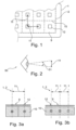
- Fig. 1 shows an enlarged section of a display device 1, in which the proportion of non-illuminating surfaces 9 in the entire display surface 2 is more than 70%.
- the centers of gravity of adjacent luminous surfaces 12 have mutual distances 11 that are smaller than the resolution of an observer.
- a very big advantage is that the luminous surfaces 12 are separated from one another by large separating areas, which are formed by non-luminous surfaces 9, and therefore on the one hand there is no scattered light from one luminous surface 12 to the other (or this is greatly reduced) and that On the other hand, dark areas of an image displayed by the display device 1 can appear even darker, since the non-luminous areas 9 predominate.
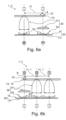
- Fig. 2 shows a purely qualitative illustration of a distance 11 which is smaller than the resolution of the viewer 50 and which appears to the viewer at an angle 51 of a maximum of two minutes of arc. At such a distance 11, most viewers 50 can no longer perceive two different pixels 10 and they therefore receive a particularly high-quality and continuous image impression.
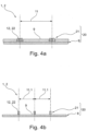
- FIG. 3a and 3b show excerpts from display devices 2 Fig. 1 wherein the display device 1 is a color display device. A side view is shown above a top view of the display surface 2. However, hatching is used here for better illustration and color differentiation. In Fig. 3a two pixels 10 are shown. A luminous area 12 is assigned to a pixel 10, with several colors being emitted to the viewer via the luminous area 12.
- composition of a pixel 10 Two possibilities for the composition of a pixel 10 are shown, on the left a composition of a pixel 10 from the colors red (close hatching from top left to bottom right), green (close hatching from bottom left to top right), blue (close hatching vertically) is preferred in a stripe arrangement and on the right from the colors red, green, blue and white (without hatching) preferably in an approximately square arrangement.
- Components with a wide hatching from top left to bottom left, such as the non-luminous surfaces 9 here, are preferably opaque.
- a pixel 10 is shown, to which three luminous areas 12 are assigned, red being able to be emitted to the viewer via a first luminous area 12, green via a second luminous area 12 and blue via a third luminous area 12.
- the distances 11.1 of the centroids of adjacent luminous areas 12 are 1/ 3 of the distance 11, which is smaller than the resolution of the viewer 50.
- Optical axes are each shown in dashed lines and in some cases a preferred lighting pattern or color of the corresponding light source 21 is indicated at the lower end of the axis and a preferred lighting pattern or color is indicated on the lighting surface 12 at the upper end of the axis.
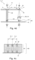
- Fig. 4a to 4e show excerpts of display devices 1 according to the invention Fig. 3a or 3b .
- the display device 1 has a lighting device 20 with a substrate 8 on which a plurality of light sources 21 are arranged, the light sources 21 preferably being small light sources 21 (e.g. VCSEL laser), ie preferably light sources 21 in which the surface area of the active luminous surface 22 is smaller or equal to the area of the corresponding luminous surface 12.
- Fig. 4a and 4d show Light sources 21 that are polychromatic, that is, that are set up to emit different, variable components of light with different wavelengths, for example red, green, blue components.
- Fig. 4b , 4c and 4e show light sources 21 that are monochromatic, ie that emit a non-variable wavelength range or a fixed mix of different wavelengths.
- the luminous surfaces 12 are each formed by one of the light sources 21.
- the non-luminous surfaces 9 of the display surface 2 are formed by surfaces of a filling material between the light sources 21, which is also the case Fig. 4b could be provided like this.
- the luminous surfaces 12 are each formed by one of the light sources 21.
- the non-luminous surfaces 9 of the display surface 2 are formed by surfaces of the substrate 8, which is also the case Fig. 4a could be provided like this.
- the active luminous surface 22 of the respective light source 21 is therefore also a luminous surface 12 of the display surface 2.
- a display device can thus be produced with just a few components, although very high-quality, bright and precisely measured light sources should advantageously be used for this purpose.
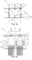
- the luminous surfaces 12 are each formed by a transparent cover element that can be illuminated by one of the light sources 21.
- the non-luminous surfaces 9 of the display surface 2 are formed by surfaces of a filling material between the light sources 21.
- Each light source 21 has a phosphor layer and an electron emitter, which is set up to cause the phosphor layer to actively glow by emitting an electron beam.
- the phosphor layer can also be viewed as a scattering element, as it distributes the incident radiation energy from one direction into several directions. There is a vacuum in a vacuum cell between the electron emitter and the phosphor layer.
- the advantage here is that, due to the inventive principle of a large intermediate surface between the luminous surfaces, a very good and economical sealing of the vacuum cells is also possible.
- Fig. 4d are the luminous surfaces 12 each by an optical scattering element 13 that can be illuminated by one of the light sources 21 (wide hatching from bottom left to top right - this type of hatching preferably means that the component hatched in this way, for example later lenses, is translucent, preferably essentially without color filtering , is) formed.
- the non-luminous surfaces 9 of the display surface 2 are formed by surfaces of a filling material between the light sources 21, at the level of the scattering elements 12. Two design options are shown, on the left with a so-called light guide (e.g a glass fiber) as a beam shaping device 30, which also serves as a concentrator 31, on the right with a lens as a concentrator 31.
- a so-called light guide e.g a glass fiber
- the resulting luminous pattern on the luminous surface 12 is as indicated above, on the left approximately the same size as the luminous pattern of the luminous surface 22, on the right slightly reduced .
- the resulting light pattern is more diffuse, preferably with colors mixed together, which occurs due to the scattering element 13, but cannot be represented advantageously in terms of drawing technology. This results in scattered radiation, but at the same time the light is concentrated onto the scattering elements 13.
- the luminous surfaces 12 are each formed by an optical color filter element 14 that can be illuminated by one of the light sources 21.
- the non-luminous surfaces 9 of the display surface 2 are formed by surfaces of a filling material between the light sources 21, at the level of the color filter elements 14.
- Each light source 21 has a UV emitter, which is set up to cause a phosphor layer, which here also acts as a scattering element 13, to actively glow by emitting a UV light beam.
- the different colors, here RGB are thus obtained through the color filter elements 14, for example through quantum dots.
- Three design options are also shown, left and right beam shaping elements 30 as in Fig. 4d and in the middle a variant without beam shaping element 30.
- Fig. 4d and 4e a collimator 34 part of the beam shaping device 30, analogous to e.g Fig. 6a .
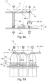
- FIG. 5a to 6d show excerpts of display devices 1 according to the invention Fig. 3a or 3b .
- These show in comparison Figs. 4a-4e larger light sources 21 and in particular optical beam shaping devices 30, which are arranged between the lighting device 20 and the display surface 2, and each beam shaping device 30 is assigned a luminous surface 12 and the beam shaping devices 30 are each set up to direct light from the lighting device 20 to the respective luminous surface 12 focus.
- the active luminous areas 22 of the light sources 21 each have an area that is larger than the respective area of the luminous area 12 of the display area 2.
- the display devices 1 each have optical beam shaping devices 30, which are arranged between the lighting device 20 and the display surface 2, and each beam shaping device 30 is assigned a luminous surface 12 and the beam shaping devices 30 are each set up to direct light from the lighting device 20 to the respective luminous surface 12 focus.
- the optical beam shaping devices 30 each have an optical collimator 34 (eg a semi-spherical collimator lens) and an optical concentrator 31 with curved ones Reflector surfaces and the optical collimator 34 is each arranged in front of the concentrator 31 with respect to a propagation direction of the light from the lighting device 20, so that light can initially be essentially collimated and then concentrated.
- a compound parabolic concentrator is provided as the concentrator 31 (represented by two opposite curved, preferably parabolically curved reflector surfaces and also in perspective Fig. 5c ), alternatively a condenser lens 31 (e.g Fig. 6a right).
- the collimators 34 are, on the one hand, prism collimators 34 (drawn by a pyramidal structure) or, alternatively, reflectors 34 (as in Fig. 6a to Fig. 6d ) available.
- the display devices 1 have light sources 21 that are approximately Lambert radiators.
- luminous surfaces 12 are each formed by an optical scattering element 13 that can be illuminated by the lighting device 20.
- the non-luminous surfaces 9 of the display surface 2 are formed by surfaces of a filling material arranged between the scattering elements 13, the filling material being shown here as a surface, but also being able to completely fill the space between adjacent beam shaping elements 30.
- the light sources are polychromatic and the light sources or their active luminous surfaces have an extent that is more than 50% of the distance 11 of the centers of gravity of the luminous surfaces 12.
- the CPCs 31 have an input 32 and an output 33 (see also Fig.
- the CPC has an optical input angle 37 which is a maximum of 30°-10°, preferably 20°, smaller than the optical output angle 36 of the prism collimator 34. Optical losses 35 can thus be minimized as much as possible.
- the combination of collimator 34 and concentrator 31 results in an effective concentration of light onto the luminous surfaces 12.
- the CPC as a non-imaging optic, achieves a very homogeneous color mixture, which is indicated by the white output light patterns.
- the scattering element 13 allows a large viewing angle.
- the beam path of the light is indicated by dashed arrows.
- Fig. 5b is a variant of the display device Fig. 5a shown, in which the extent of the light source 21 is less than 50% of the distance 11, but greater than the extent of the luminous surface 12.
- Fig. 5d are different from Fig. 5a the light sources are monochromatic and the luminous surfaces 12 are each formed by an optical color filter element that can be illuminated by the lighting device 20 and is at the same time a scattering element 13. Furthermore, there are distances 11.1 between the luminous surfaces 12, which amount to a third of the distance 11.
- the display devices 1 have light sources 21 which are the same size or larger than the luminous areas 12 in terms of area (for example based on the active luminous area of a light source). Otherwise it is Fig. 6a similar to Fig. 5a , where Fig. 6a in contrast to Fig. 5a Collimators 34 shows which surround the light sources 21 as a parabolic reflector. The optical collimator 34 is still arranged in front of the concentrator 31 with respect to a propagation direction of the light from the lighting device 20, so that light can first be essentially collimated and then concentrated.
- an RGBW light source is shown on the right and, instead of a CPC as a concentrator 31, a condenser lens, here a non-imaging condenser lens, which also brings about good homogenization of the light shining through the luminous surface 12.
- Fig. 6b is similar to Fig. 6a , wherein the light sources 21 are monochromatic and the luminous surfaces 12 are each formed by an optical color filter element that can be illuminated by the lighting device 20 and is at the same time a scattering element 13. Furthermore, there are distances 11.1 between the luminous surfaces 12, which amount to a third of the distance 11.
- Fig. 6c is similar to Fig.
- Fig. 6a wherein the light sources 21 are monochromatic, here white, and color filter elements 14 are arranged directly on the light sources 21. Furthermore, a design option with an imaging condenser lens 31 is shown on the right.
- Fig. 6d is similar to Fig. 6a , wherein the light sources 21 are monochromatic, here for example essentially emitting blue and/or UV.
- the luminous surfaces 12 are each formed by an optical color filter element 14 that can be illuminated by the lighting device 20.
- Each light source 21 has a blue and/or UV emitter, which is set up to cause a phosphor layer, which here also acts as a scattering element 13, to actively glow by emitting a blue and/or UV light beam.
- the different colors, here RGB are thus obtained through the color filter elements 14.
- Color filter elements 14 are arranged directly on the light sources 21 (eg quantum dots).
- Fig. 7 With reference to Fig. 7 becomes the description Fig. 1 referred, whereby Fig. 7 differs in that it additionally has functional elements 40.1.
- the functional elements 40.1 shown are arranged between the luminous surfaces 12 or on the non-illuminating surfaces 9.
- the arrangement and size of the functional elements 40.1 shown here is to be understood as an example.
- Functional elements 40.1 can be arranged in a repeating pattern, whereby a large number of areas between the luminous surfaces 12 are used can be.
- the size and shape of the functional elements 40.1 is also variable. Of course, any polygonal shape is also possible.
- the functional elements 40.1 shown can be, for example, a solar element and/or a sensor.
- a sensor can be, for example, a temperature sensor, a distance sensor, a pressure sensor, a gas sensor or an image sensor.
- a solar element is used to convert solar energy into electrical energy, which extends the energy supply to the display device by, for example, charging a battery or makes it possible in the first place.
- 8a and 8b differ only in the functional element 40.1, which is arranged on the non-luminous surface 9.
- the functional element 40.1 is attached to the top of the display surface 2. But it is also possible to arrange the functional elements 40.1 on the underside, i.e. on the side facing away from the viewer.
- the functional element 40.1 is designed as a piezo element, more precisely as a pressure sensor. An altimeter, for example, can be implemented using the pressure sensor. It is also possible to generate haptic feedback in the form of vibration with a piezo element.
- Fig. 9a a functional element 40.1 between two light sources 21 of the lighting device 20.
- the functional element 40.1 is arranged on the non-luminous surface 9 and designed as a gas sensor.
- Fig. 4d also meets the description of Fig. 9b to, whereby Fig. 9b is expanded by two functional elements 40.1 and 40.2. While a functional element 40.1 is arranged on the substrate 8 of the lighting device 20 between two light sources 21 and is designed as a capacitive sensor, the other functional element 40.2 forms a solar element. In order to enlarge the surface of the functional element 40.2 or the solar element and thus increase the energy yield, the functional element 40.2 has a polygonal shape. The polygon-shaped, triangular functional element 40.2 also forms the entire non-illuminating surface 9 of the display surface 2 between two luminous surfaces 12.
- the functional element can 40.2 only take up part of the non-illuminating area 9 of the display area 2.
- the beam shaping element 40.3 which is translucent and made of transparent material, is arranged between the luminous surfaces 12 and between the non-illuminating surfaces 9 and directs passing light onto the beam detector device 40.4 by refraction. In this way it is possible to realize a plenoptic camera, which can be formed by several functional elements 40.3 and 40.4. The available light of a scene, which hits the lens or the beam shaping element 40.3 from more than one direction, is thus imaged onto the beam detector device 40.4 or an image sensor.
- a plenoptic camera In contrast to a conventional camera, a plenoptic camera not only records the position and intensity of a light beam that hits an image sensor or the beam detector device 40.4, but also the direction from which the light beam is incident. A so-called light field measurement can thus be carried out. Consequently, it is using the design shown in Figure 9c , possible to arrange several lenses or beam shaping elements 40.3 in front of several image sensors or beam detector devices 40.4 in a simple manner.
- the advantages of a plenoptic camera are the high depth of field, no waiting for a focusing process and subsequent adjustment of the focal plane of a recorded object or image.
- the beam shaping element 40.3 is in Figure 9c arranged between two luminous surfaces 12 and designed in a hemispherical shape, but it can also have a different shape - depending on the application. So are e.g. B. polygonal shapes are also possible.
- the beam detector device 40.4 is arranged on the substrate 8 and between two light sources 21 and in the present case is a light field sensor which - as described above - detects the position and intensity, but also the direction of a light beam.
- An exemplary light beam is shown with an interrupted dashed line, which occurs on the beam shaping element 40.3, is refracted by it and further directed onto the beam detector device 40.4.
- a functional element 40.1 is arranged below the left non-luminous surface 9 of the display surface 2, the right non-luminous surface 9 being identical to that Figure 9b is designed.
- the polygon-shaped functional element 40.2 the description will be given for the sake of brevity Figure 9b referred to, which is also applicable here.
- the left functional element 40.1 is designed as a piezo element, which can generate haptic feedback and at the same time functions as a pressure sensor. This means that an input from a user can be detected on the display device 1 and at the same time haptic feedback can be generated for the input.
- the non-illuminating surfaces 9, preferably the entire display surface 2, preferably have a reflectance of diffuse reflection and/or specular reflection of less than 50%.
- the non-luminous surfaces 9 preferably have a dark color or are black and/or they have an average roughness in the range of 0.2 ⁇ m and 1.0 ⁇ m and/or are coated using an anti-reflective coating.
- An electronic compensation device is also preferably present, by means of which a minimum brightness of the luminous surfaces 12 can be automatically adjusted for adapting the display of black image pixels depending on the ambient brightness.
- This invention creates a revolutionary improvement in the quality of display devices.
- the image quality is increased by the principle of making the non-illuminating areas between the luminous areas as large as possible, for example by making the proportion of non-illuminating areas of the total display area at least 70%, as this improves the contrast and allows a lot of energy to be saved , which is particularly important for portable devices.
- special intensive light sources e.g.
- lasers or micro-LEDs or micro-OLEDS are used or special beam shaping devices, which are behind the display area as seen from the viewer, are used to concentrate light on the illuminated areas and thus A brightness boost is achieved so that the brightness average is similar to that of normal display devices, but with better contrast and lower energy consumption, depending on the ambient light.
Description
Die Erfindung betrifft eine Farbanzeigevorrichtung mit einer Anzeigefläche mit mehreren Pixeln. Solche Anzeigevorrichtungen sind im Stand der Technik z.B. als LCD-Anzeigevorrichtungen oder OLED-Anzeigevorrichtungen bekannt. Nachteilig an solchen Anzeigevorrichtungen ist der begrenzte Kontrastumfang, den diese Anzeigevorrichtungen aufweisen. Die
Die
Ein weiteres Farbanzeigesystem ist in der
Aufgabe der vorliegenden Erfindung ist es, Farbanzeigevorrichtungen der erst genannten Art, d.h. Anzeigevorrichtung mit einer Anzeigefläche mit mehreren Pixeln, z.B. LCD- oder OLED-Anzeigevorrichtungen, zu verbessern, insbesondere die Anzeigequalität und/oder den visuellen Eindruck einer solchen Anzeige zu verbessern und/oder die Anzeigevorrichtung energieeffizienter zu gestalten und/oder die Anzeigevorrichtung für weitere Anwendungen zu erweitern.The object of the present invention is to improve color display devices of the first type mentioned, i.e. display device with a display area with several pixels, e.g. LCD or OLED display devices, in particular to improve the display quality and / or the visual impression of such a display and / or to make the display device more energy efficient and/or to expand the display device for further applications.
Die Aufgabe wird durch den unabhängigen Anspruch gelöst. Vorteilhafte Weiterbildungen sind in den Unteransprüchen definiert.The task is solved by the independent claim. Advantageous further training is defined in the subclaims.
Insbesondere wird die Aufgabe gelöst durch eine Farbanzeigevorrichtung mit einer Anzeigefläche bestehend aus nicht leuchtenden Flächen und Leuchtflächen, wobei die Flächenschwerpunkte benachbarter Leuchtflächen gegenseitige Abstände aufweisen, die kleiner sind, als das Auflösungsvermögen eines Betrachters und wobei vorzugsweise der Anteil der nicht leuchtenden Flächen an der gesamten Anzeigefläche mehr als 70% beträgt.In particular, the task is solved by a color display device with a display area consisting of non-luminous areas and luminous areas, the centers of gravity of adjacent luminous areas having mutual distances that are smaller than the resolution of a viewer and preferably the proportion of non-illuminating areas in the total display area is more than 70%.
Hierdurch wird zunächst eine Farbanzeigevorrichtung bereitgestellt, welche auf bekannte Weise so hochauflösend ist, dass der menschliche Betrachter die einzelnen Leuchtflächen nicht voneinander unterscheiden kann. Darüberhinaus wird jedoch ein besonderer Vorteil durch eine bewusste und dem allgemeinen Bestreben einer Leuchtflächenmaximierung genau entgegengesetzte Verkleinerung des Anteils der Leuchtflächen an der Anzeigefläche und eine Vergrößerung der nicht leuchtenden Flächen zwischen den Leuchtflächen erhalten. Hierdurch werden dunkle Bereiche dann auch in der Tat dunkel bleiben können, da sie im Verhältnis viel größer als die leuchtenden Flächen sind, noch verstärkt z.B. bei einem Anteil der nicht leuchtenden Flächen von z.B. mehr als 95% (ein bevorzugtes Merkmal dieser Erfindung, siehe unten), und weniger lichtreflektierend sind, was insbesondere vorteilhaft ist in dunkleren Teilen des Bildes und/oder bei starkem Umgebungslicht. Das wiederum bringt ein großes Stromersparnis-Potential mit sich, da weniger Licht notwendig ist, um einen guten Kontrastwert zu erreichen (bei vorhandenem Umgebungslicht). Weiterhin wird eine zusätzliche Kontrasterhöhung erzielt, da zwischen den einzelnen Leuchtflächen ein größere Trennung durch nicht leuchtende Flächen vorhanden ist und somit einerseits kein oder nur ein wesentlich reduzierter Leucht-"Crosstalk" zwischen benachbarten Leuchtflächen erfolgt.This initially provides a color display device which, in a known manner, has such a high resolution that the human observer cannot distinguish the individual illuminated areas from one another. In addition, however, a special advantage comes from a conscious and general effort Luminous area maximization results in exactly the opposite reduction in the proportion of luminous areas in the display area and an enlargement of the non-illuminating areas between the luminous areas. As a result, dark areas can actually remain dark because they are relatively much larger than the luminous areas, even more so with a proportion of non-luminous areas of, for example, more than 95% (a preferred feature of this invention, see below ), and are less light-reflecting, which is particularly advantageous in darker parts of the image and/or in strong ambient light. This in turn brings with it a great potential for energy savings, as less light is necessary to achieve a good contrast value (with ambient light available). Furthermore, an additional increase in contrast is achieved because there is a greater separation between the individual luminous areas due to non-luminous areas and therefore, on the one hand, there is no or only a significantly reduced luminous "crosstalk" between adjacent luminous areas.
Unter einer Farbanzeigevorrichtung bzw. einem Display wird eine Einrichtung verstanden, welche eingerichtet ist, bevorzugt digitale oder digitalisierte Bilder, Text, Graphik oder Video, welche jeweils aus einzelnen Pixeln zusammengesetzt ist, anzuzeigen. Z.B. ist sie ein Display eines Handheld-Devices (z.B. Mobilfunkgerät/Smartphone, Armband/Taschenuhr, Pocket-Mediaplayer, Tablet etc.), eines konventionellen Computers (Laptop, Desktop etc.), eines Fernsehers oder einer Werbe-/Informationsanzeigetafel (z.B. in U-Bahnen, Sportstadien oder Kaufhäuser, an Hauswänden etc.).A color display device or display is understood to mean a device which is set up to display preferably digital or digitized images, text, graphics or video, each of which is composed of individual pixels. For example, it is a display of a handheld device (e.g. mobile device/smartphone, bracelet/pocket watch, pocket media player, tablet, etc.), a conventional computer (laptop, desktop, etc.), a television or an advertising/information display board (e.g. in Subways, sports stadiums or department stores, on house walls, etc.).
Die Anzeigefläche ist eine dem Betrachter zugewandte Fläche der Anzeigevorrichtung, innerhalb welcher die einzelnen Pixel angeordnet sind. Die Anzeigefläche ist bevorzugt begrenzt durch eine (imaginäre) Linie, welche entlang der äußersten Pixel, bevorzugt entlang der äußersten Leuchtflächen der Anzeigevorrichtung verläuft. Bevorzugt verläuft um die Anzeigefläche herum in der Regel ein Rahmen, welcher z.B. für mechanische Stabilität sorgt, der jedoch umso vorteilhafter für z.B. das Design ist, je dünner er ist. Unter Leuchtfläche wird eine Fläche verstanden, von welcher aus in einem eingeschaltetem Modus Lichtstrahlen zu dem Betrachter ausgehen. Die Lichtstrahlen können entweder direkt in der Fläche generiert bzw. ausgesendet werden (z.B. durch eine in der Leuchtfläche angeordnete aktive Lichtquelle wie einer LED) oder sie können durch die Leuchtfläche zu dem Betrachter weitergeleitet werden (Hintergrundbeleuchtung wie bei LCD Bildschirmen). Die Fläche erststreckt sich bevorzugt teilweise oder ganz durch Luft bzw. einen körperlosen Bereich. Dabei ist sie bevorzugt durch einen Rahmen oder eine Maske umrahmt. Vereinfacht dargestellt, kann eine Leuchtfläche also ein Loch bzw. eine Bohrung sein, welche Licht bzw. Lichtstrahlen eine Öffnung bietet, von welcher aus die Lichtstrahlen zu dem Betrachter gelangen. Besonders bevorzugt besteht die Fläche teilweise oder ganz aus einem zumindest teilweise oder zu einem bestimmten Grad oder komplett transparenten Festkörper oder verläuft teilweise oder ganz durch diesen. Z.B. sind die Leuchtflächen diejenigen Flächen der Anzeigevorrichtung welche die Subpixel darstellen und bei einem Leuchten der Subpixel das Licht an den Betrachter ausstrahlen. Die Form der Leuchtfläche ist beliebig, bevorzugt viereckig oder rund. Bevorzugt ist mindestens eine Leuchtflächenform in gleichmäßiger Wiederholung identisch vorhanden. Eine Leuchtfläche ist bevorzugt einem Pixel zugeordnet. Ferner ist es günstig, wenn ein Pixel oder ein Subpixel, beispielsweise RGB-Subpixel, mehrere Leuchtflächen aufweist. Auf diese Weise kann die Lichtintensität sowie die Farbdarstellung feinstufiger realisiert werden. Des Weiteren ist es bevorzugt, dass ein Pixel mindestens zwei Leuchtflächen aufweist, sodass eine Lichtabstrahlung in mehrere Raumrichtungen, vorzugsweise in entgegengesetzte Richtungen, realisierbar ist. Auf diese Weise kann z. B. eine Anzeigefläche einer Anzeigevorrichtung mehrere Anzeigeflächen dem Betrachter zur Verfügung stellen, sodass beispielsweise ein Tablet-Computer auf jeder Seite bzw. auf der Ober- und Unterseite ein Display aufweist, um die Handhabung noch weiter zu vereinfachen. Selbstverständlich können auch weitere dem Betrachter zugewandte Flächen Licht an diesen senden. Auch in diesem Zusammenhang wird unter einer Leuchtfläche eine Fläche verstanden, von welcher aus in einem eingeschaltetem Modus Lichtstrahlen zu dem Betrachter ausgehen.The display area is a surface of the display device facing the viewer, within which the individual pixels are arranged. The display area is preferably delimited by an (imaginary) line which runs along the outermost pixels, preferably along the outermost luminous areas of the display device. Preferably, a frame generally runs around the display surface, which, for example, ensures mechanical stability, but the thinner it is, the more advantageous it is for the design, for example. A luminous surface is understood to be a surface from which light rays emanate to the viewer when the mode is switched on. The light rays can either be generated or emitted directly in the surface (e.g. by an active light source such as an LED arranged in the luminous surface) or they can be forwarded through the luminous surface to the viewer (backlighting as in LCD screens). The surface preferably extends partially or completely through air or an incorporeal area. It is preferably framed by a frame or a mask. To put it simply, a luminous surface can be a hole or a Be a hole, which offers light or light rays an opening from which the light rays reach the viewer. Particularly preferably, the surface consists partially or entirely of a solid body that is at least partially or to a certain degree or completely transparent or runs partially or entirely through it. For example, the luminous areas are those areas of the display device which represent the subpixels and emit the light to the viewer when the subpixels light up. The shape of the light surface is arbitrary, preferably square or round. Preferably, at least one luminous surface shape is identically present in uniform repetition. A luminous area is preferably assigned to a pixel. Furthermore, it is favorable if a pixel or a subpixel, for example RGB subpixel, has several luminous areas. In this way, the light intensity and the color representation can be realized in a more fine-grained manner. Furthermore, it is preferred that a pixel has at least two luminous surfaces, so that light emission in several spatial directions, preferably in opposite directions, can be realized. In this way, e.g. B. a display area of a display device makes several display areas available to the viewer, so that, for example, a tablet computer has a display on each side or on the top and bottom in order to simplify handling even further. Of course, other surfaces facing the viewer can also send light to the viewer. In this context, too, a luminous surface is understood to mean a surface from which light rays emanate to the viewer when the mode is switched on.
Unter einer nicht leuchtenden Fläche werden Bereiche verstanden, welche zwischen den Leuchtflächen vorhanden sind und welche von sich aus nicht leuchten oder hinterleuchtet sind. Bevorzugt ist eine oder sind alle nicht leuchtenden Flächen zu mindestens 90 % lichtundurchlässig.A non-illuminating surface means areas that are present between the luminous surfaces and which do not glow on their own or are backlit. Preferably one or all non-luminous surfaces are at least 90% opaque.
Der Flächenschwerpunkt einer Leuchtfläche ist der geometrische Schwerpunkt oder Schwerpunkt der Fläche, welcher mathematisch der Mittelung aller Punkte innerhalb der Fläche entspricht.The center of gravity of a luminous surface is the geometric center of gravity or centroid of the surface, which mathematically corresponds to the averaging of all points within the surface.
Abstände, die kleiner sind als das Auflösungsvermögen eines Betrachters, sind bevorzugt derart, dass die Pixel oder Leuchtflächen so nahe zusammen angeordnet sind, dass ein Betrachter, dessen Augen sich bevorzugt in einem Abstand zu der Anzeigevorrichtung befinden, welcher für die konkrete Art der Anzeigevorrichtung bei der Benutzung der Anzeigevorrichtung üblich ist, zwei benachbarte Pixel oder Leuchtflächen nicht mehr voneinander unterscheiden kann.Distances that are smaller than the resolution of a viewer are preferably such that the pixels or luminous surfaces are arranged so close together that a viewer, whose eyes are preferably at a distance from the display device, which is appropriate for the specific type of display device As is common when using the display device, two neighboring pixels or luminous areas can no longer be distinguished from one another.
Bevorzugt sind die Abstände, die kleiner sind als das Auflösungsvermögen des Betrachters, solche Abstände, die bei dem Betrachter unter einem Winkel von maximal zwei Winkelminuten erscheinen. Hierdurch sind die Pixel oder Leuchtflächen für einen Großteil der Betrachter nicht mehr unterscheidbar, da das menschliche Auflösungsvermögen in ungünstigen Fällen in etwa 2 Winkelminuten entspricht. Besonders bevorzugt erscheinen die Abstände dem Betrachter maximal unter einem Winkel von 1 Winkelminute, besonders bevorzugt 0,5 Winkelminuten, besonders bevorzugt 0,25 Winkelminuten. Hierdurch sind für nahezu alle menschlichen Betrachter die Pixel oder Leuchtflächen nicht mehr unterscheidbar. Je kleiner der maximale Winkel, desto weniger Betrachter existieren, deren Sehfähigkeit zur Unterscheidung zweier Pixel oder Leuchtflächen ausreicht.Preferred are the distances that are smaller than the resolution of the viewer, such distances that appear to the viewer at an angle of a maximum of two angular minutes. As a result, the pixels or illuminated areas are no longer distinguishable for the majority of viewers, since in unfavorable cases the human resolution power corresponds to around 2 angular minutes. Particularly preferably, the distances appear to the observer at a maximum angle of 1 angular minute, particularly preferably 0.5 angular minute, particularly preferably 0.25 angular minute. As a result, the pixels or illuminated areas are no longer distinguishable for almost all human observers. The smaller the maximum angle, the fewer observers there are whose vision is sufficient to distinguish between two pixels or illuminated areas.
Bevorzugt weist das oder weisen die Augen des Betrachters einen Abstand zu der Anzeigefläche auf, welche für die konkrete Art der Anzeigevorrichtung bei der Benutzung der Anzeigevorrichtung üblich ist. Zum Beispiel beträgt der Abstand 5 cm bis 1,20 m, bevorzugt 15 cm bis 60 cm für Displays von Handheldgeräten (Mobiltelefon, Uhr, Tablet-Computer), 25 cm bis 2 m, bevorzugt 40 cm bis 1 m für Displays von Desktop-Computer, 1 m bis 7 m bevorzugt 2 m bis 5 m für Fernsehgeräte und/oder 2 m bis 100 m, bevorzugt 5 m bis mehr als 100 m für Werbe-/Informationsanzeigetafeln. Besonders bevorzugt sind die Abstände, die kleiner als das Auflösungsvermögen des Betrachters sind, kleiner als 1 mm, wobei dies z.B. ein Abstand im Falle eines Fernsehers ist, bei dem der Benutzer in üblicher Betrachtungsentfernung (> 2m) die einzelnen Pixel oder Leuchtflächen dann nicht mehr voneinander unterscheiden kann.Preferably, the viewer's eyes or eyes are at a distance from the display surface, which is usual for the specific type of display device when using the display device. For example, the distance is 5 cm to 1.20 m, preferably 15 cm to 60 cm for displays of handheld devices (mobile phones, watches, tablet computers), 25 cm to 2 m, preferably 40 cm to 1 m for displays of desktop devices. Computers, 1 m to 7 m preferably 2 m to 5 m for televisions and/or 2 m to 100 m, preferably 5 m to more than 100 m for advertising/information display boards. Particularly preferred are the distances that are smaller than the viewer's resolution, less than 1 mm, which is, for example, a distance in the case of a television in which the user can no longer see the individual pixels or luminous areas at the usual viewing distance (> 2m). can distinguish from each other.
Z.B. ist die Anzeigevorrichtung ein Desktop-Computer mit einer minimalen Nutzerdistanz (bezogen auf das Auge) von 50 cm. In der hypothetischen Annahme, dass z.B. 70% der potentiellen Benutzer über kein besseres Auflösungsvermögen als 0,6 Winkelminuten verfügen, werden die Pixel oder Leuchtflächen der Anzeigevorrichtung kleiner gleich 87 µm, bevorzugt 80 µm) für einen Sicherheitspuffer, voneinander beabstandet, damit für zumindest 70% der Benutzer bei der üblichen Benutzung der Anzeigevorrichtung eine besonders hochwertige Darstellung ermöglicht wird, da für sie einzelne Leuchtflächen nicht unterscheidbar sind. Es resultiert eine Auflösung der Anzeigevorrichtung von 317 DPI, bevorzugt 320 DPI mit Sicherheitspuffer.For example, the display device is a desktop computer with a minimum user distance (based on the eye) of 50 cm. In the hypothetical assumption that, for example, 70% of potential users do not have a resolution better than 0.6 angular minutes, the pixels or luminous areas of the display device (less than or equal to 87 µm, preferably 80 µm) are spaced apart from one another for a safety buffer, thus for at least 70 % of users are able to achieve a particularly high-quality display during normal use of the display device, since individual illuminated areas cannot be distinguished for them. The result is a resolution of the display device of 317 DPI, preferably 320 DPI with a security buffer.
Erfindungsgemäß betragen die Abstände, die kleiner als das Auflösungsvermögen des Betrachters sind, maximal 190 µm, bevorzugt maximal 80 µm, besonders bevorzugt maximal 50 µm. Hierdurch wird erreicht, dass, auch wenn der Betrachter der Anzeigefläche näher als üblich kommt, er einzelne Pixel oder Leuchtflächen nicht voneinander unterscheiden kann. Je nach Auflösungsvermögen und Akkommodationsfähigkeit des individuellen Betrachters ist es damit sogar egal wie nahe der individuelle Betrachter der Anzeigevorrichtung kommt, denn er kann selbst bei optimaler Ausnutzung seiner Sehkraft und einem Annähern bis an die Naheinstellgrenze seines Auges nicht die einzelnen Pixel oder Leuchtflächen voneinander unterscheiden.According to the invention, the distances that are smaller than the resolution of the viewer are a maximum of 190 μm, preferably a maximum of 80 μm, particularly preferably a maximum of 50 μm. This ensures that, even if the viewer comes closer to the display area than usual, he cannot distinguish individual pixels or illuminated areas from one another can. Depending on the resolution and accommodation ability of the individual viewer, it does not matter how close the individual viewer comes to the display device, because even if he makes optimal use of his vision and approaches the closest focusing limit of his eye, he cannot distinguish the individual pixels or luminous areas from one another.
Bevorzugt beträgt die Ausdehnung einer, bevorzugt jeder, Leuchtfläche höchstens 70 µm, bevorzugt höchstens 25 µm, besonders bevorzugt höchstens 10 µm oder sogar höchstens 5 µm. Hierdurch wird erreicht, dass der Betrachter Leuchtflächen mit bloßem Auge (in ausgeschaltetem Zustand) nicht erkennen kann und der Kontrast höher wirkt. Die Ausdehnung ist bevorzugt eine Ausdehnung, bevorzugt die maximale Ausdehnung, einer Leuchtfläche parallel zur Anzeigefläche. Besonders bevorzugt ist die Ausdehnung kleiner oder gleich der Wellenlänge des sichtbaren und/oder des durchzuleitenden Lichts. Sie beträgt z.B. höchstens 2 µm, bevorzugt höchstens 1 µm oder höchstens 0,5 µm. Hierdurch ist insbesondere aufgrund des Rayleigh-Kriteriums der Austrittswinkel des von der Leuchtfläche ausgehenden Lichts größer.The extent of one, preferably each, luminous surface is preferably at most 70 μm, preferably at most 25 μm, particularly preferably at most 10 μm or even at most 5 μm. This ensures that the viewer cannot see illuminated surfaces with the naked eye (when switched off) and the contrast appears higher. The extent is preferably an extent, preferably the maximum extent, of a luminous surface parallel to the display surface. Particularly preferably, the extent is less than or equal to the wavelength of the visible and/or the light to be transmitted. It is, for example, at most 2 µm, preferably at most 1 µm or at most 0.5 µm. As a result, the exit angle of the light emanating from the luminous surface is larger, particularly due to the Rayleigh criterion.
Der Anteil der nicht leuchtenden Flächen an der gesamten Anzeigefläche ist bevorzugt der Anteil der Summe aller Flächenanteile der nicht leuchtenden Flächen am Flächeninhalt der Gesamtanzeigefläche. Er ist bevorzugt invers zum Anteil der Leuchtflächen an der Anzeigefläche, d.h. der Anteil der nicht leuchtenden Flächen und der Anteil der leuchtenden Flächen an der gesamten Anzeigefläche ergibt bevorzugt 100%.The proportion of the non-illuminating areas in the total display area is preferably the proportion of the sum of all the areas of the non-illuminating areas in the area of the total display area. It is preferably inverse to the proportion of luminous areas on the display area, i.e. the proportion of non-illuminating areas and the proportion of luminous areas on the entire display area are preferably 100%.
Der Anteil von Leuchtflächen an der Anzeigefläche ist bevorzugt der Anteil der Summe aller Flächenanteile der Leuchtflächen an der gesamten Anzeigefläche.The proportion of luminous areas in the display area is preferably the proportion of the sum of all areas of the luminous areas in the entire display area.
Die nicht leuchtenden Flächen der Anzeigefläche ergeben sich bisher üblicherweise aufgrund von Verdrahtungen der Ansteuerung von LCD-Zellen und man ist im Stand der Technik bestrebt, diese übrigen Flächen möglichst zu minimieren, damit die Leuchtflächen so viel Platz als möglich erhalten. Daher ist es bei einer bevorzugten Anzeigevorrichtung von Vorteil, wenn in den Raum zwischen den Leuchtflächen mindestens ein Funktionselement angeordnet ist, um den Platz zwischen den Leuchtflächen zu nutzen. Somit können mithilfe des mindestens einen Funktionselements weitere Funktionen integriert werden. So kann das mindestens eine Funktionselement beispielsweise ein Solarelement und/oder einen Sensor aufweisen. Bei einem solchen Sensor kann es sich beispielsweise um einen Temperatursensor, einen Abstandssensor, einen Drucksensor, einen Gassensor oder einen Bildsensor handeln.The non-luminous areas of the display area have so far usually resulted from wiring for the control of LCD cells and the prior art strives to minimize these remaining areas as much as possible so that the luminous areas receive as much space as possible. Therefore, in a preferred display device, it is advantageous if at least one functional element is arranged in the space between the luminous surfaces in order to use the space between the luminous surfaces. Additional functions can thus be integrated using the at least one functional element. For example, the at least one functional element can have a solar element and/or a sensor. Such a sensor can be, for example, a temperature sensor, a distance sensor, a pressure sensor, a gas sensor or an image sensor.
Bevorzugt ist der Anteil der nicht leuchtenden Flächen an der gesamten Anzeigefläche größer als 80%, bevorzugt größer als 90%, besonders bevorzugt größer als 95%, ganz besonders bevorzugt größer als 98% und schließlich noch weiter bevorzugt mindestens 99%.The proportion of non-illuminating areas in the total display area is preferably greater than 80%, preferably greater than 90%, particularly preferably greater than 95%, very particularly preferably greater than 98% and finally even more preferably at least 99%.
Bevorzugt ist analog dazu der Anteil der Leuchtflächen an der gesamten Anzeigefläche höchstens 20%, bevorzugt höchstens 10%, besonders bevorzugt höchstens 5%, ganz besonders bevorzugt höchstens 2% und schließlich noch weiter bevorzugt höchstens 1%. Je größer der Anteil der nicht leuchtenden Flächen und/oder je kleiner der Anteil der Leuchtflächen, desto stärker sind die eingangs erwähnten erfindungsgemäßen Effekte.Analogously to this, the proportion of the luminous areas in the entire display area is preferably at most 20%, preferably at most 10%, particularly preferably at most 5%, very particularly preferably at most 2% and finally even more preferably at most 1%. The larger the proportion of non-illuminating areas and/or the smaller the proportion of luminous areas, the stronger are the effects according to the invention mentioned at the beginning.
Die erfindungsgemäße Farbanzeigevorrichtung weist mindestens ein Funktionselement auf. Mithilfe des mindestens einen Funktionselements kann die Anzeigevorrichtung um weitere Funktionen erweitert werden. So kann das mindestens eine Funktionselement beispielsweise ein Solarelement zum Umwandeln von Sonnenenergie in elektrische Energie aufweisen. Dies erlaubt die Energieversorgung der Anzeigevorrichtung. Somit kann ein Teil oder die gesamte benötigte Energie für die Anzeigevorrichtung aus Sonnenenergie gewonnen werden, wodurch z. B. eine Batterie der Anzeigevorrichtung entlastet oder sogar eingespart werden kann.The color display device according to the invention has at least one functional element. With the help of the at least one functional element, the display device can be expanded to include further functions. For example, the at least one functional element can have a solar element for converting solar energy into electrical energy. This allows the display device to be supplied with energy. Thus, part or all of the energy required for the display device can be obtained from solar energy, whereby e.g. B. a battery of the display device can be relieved or even saved.
Auch ist es möglich, dass das mindestens eine Funktionselement einen Sensor aufweist, vorzugsweise einen zweidimensionalen und/oder dreidimensionalen Sensor. Ferner ist es bevorzugt, wenn das mindestens eine Funktionselement einen Bildsensor oder einen berührungsempfindlichen Sensor aufweist, insbesondere ein Piezoelement. Ein Sensor kann dabei die Anzeigevorrichtung um eine weitere Anwendung erweitern, z. B. um die Detektion von Eingaben durch einen Benutzer. Benutzereingaben können beispielsweise mithilfe eines Temperatursensors, eines Abstandssensors, eines Drucksensors, eines Gassensors oder eines Bildsensors detektiert werden.It is also possible for the at least one functional element to have a sensor, preferably a two-dimensional and/or three-dimensional sensor. Furthermore, it is preferred if the at least one functional element has an image sensor or a touch-sensitive sensor, in particular a piezo element. A sensor can expand the display device to include a further application, e.g. B. about the detection of input by a user. For example, user input can be detected using a temperature sensor, a distance sensor, a pressure sensor, a gas sensor or an image sensor.
Dabei ist es vorteilhaft, wenn der Temperatursensor einen Wärmefühler mit Schwingquarz oder ein Thermoelement, das eine Temperaturdifferenz durch den Seebeck-Effekt in eine elektrische Spannung umwandelt, aufweist. Auch ist es möglich, dass der Temperatursensor ein pyroelektrisches Material aufweist, das die Ladungsträgerdichte an der Oberfläche bei Temperaturschwankungen durch Veränderung der spontanen Polarisation verändert, oder einen mechanisch arbeitenden Temperaturschalter, z. B. Bimetallschalter, der mithilfe von Verformung eines Bimetalls einen Schalter betätigt.It is advantageous if the temperature sensor has a heat sensor with a quartz oscillator or a thermocouple that converts a temperature difference into an electrical voltage using the Seebeck effect. It is also possible for the temperature sensor to have a pyroelectric material that changes the charge carrier density on the surface in the event of temperature fluctuations by changing the spontaneous polarization, or a mechanically operating temperature switch, e.g. B. Bimetal switch, which operates a switch by deforming a bimetal.
Ferner ist es von Vorteil, wenn der Abstandssensor nach dem Funktionsprinzip der variablen Kapazität arbeitet. Dabei weist ein kapazitiver Sensor zwei voneinander isolierte Plattenelemente auf, die einen Kondensator bilden, wobei z. B. der Finger eines Nutzer ein Dielektrikum darstellt. Das Dielektrikum im Kondensator variiert dessen Kapazität, welche durch Spannungsmessung leicht detektiert werden kann. Somit handelt es sich bei einem Abstandssensor um einen berührungsempfindlichen Sensor.It is also advantageous if the distance sensor works according to the functional principle of variable capacitance. A capacitive sensor has two plate elements that are insulated from each other and form a capacitor, e.g. B. a user's finger represents a dielectric. The dielectric in the capacitor varies its capacity, which can be easily detected by measuring voltage. A distance sensor is therefore a touch-sensitive sensor.
Auch ist es günstig, wenn der Drucksensor piezoresistiv oder piezoelektrisch ausgebildet ist. Bei einem piezoresistiven Drucksensor verformt der zu messende Druck eine Membran, welche über aufgebrachte elektrische Widerstände verfügt. Die druckabhängige Verformung der Membran verformt ebenfalls auf der Membran eindiffundierten Widerstände, wodurch es zur Ausbildung einer elektrischen Spannung kommt, welche ebenfalls auf einfache Weise gemessen werden kann. Bei einem piezoelektrischen Drucksensor verursacht der zu messende Druck eine Ladungstrennung in einem Kristall, wodurch eine elektrische Spannung erzeugt wird. Der Druck verschiebt im Inneren des Kristalls Ladungen, wodurch sich an der Oberfläche eine elektrische Ladung proportional zur Kraft bildet. Soll der Sensor für die Druckmessung eingesetzt werden, muss erst über eine Membran der Druck proportional in eine Kraft umgeformt werden. Folglich handelt es sich bei einem Drucksensor um einen berührungsempfindlichen Sensor, wobei der piezoresistive und der piezoelektrische Drucksensor ein Piezoelement aufweisen. Auch ist es denkbar, mithilfe des Drucksensors eine Kraft zu erzeugen und somit ein haptisches Feedback in Form einer Vibration zu gewährleisten, indem z. B. das Piezoelement des Drucksensors in Zyklen aktiviert und deaktiviert wird.It is also advantageous if the pressure sensor is piezoresistive or piezoelectric. With a piezoresistive pressure sensor, the pressure to be measured deforms a membrane that has applied electrical resistances. The pressure-dependent deformation of the membrane also deforms resistances diffused onto the membrane, which leads to the formation of an electrical voltage, which can also be measured in a simple manner. With a piezoelectric pressure sensor, the pressure being measured causes charge separation in a crystal, which creates an electrical voltage. The pressure shifts charges inside the crystal, forming an electric charge on the surface proportional to the force. If the sensor is to be used for pressure measurement, the pressure must first be converted proportionally into a force via a membrane. Consequently, a pressure sensor is a touch-sensitive sensor, with the piezoresistive and piezoelectric pressure sensors having a piezo element. It is also conceivable to use the pressure sensor to generate a force and thus ensure haptic feedback in the form of a vibration, for example. B. the piezo element of the pressure sensor is activated and deactivated in cycles.
Günstigerweise ist der Sensor des mindestens einen Funktionselements ein Gassensor, welcher vorzugsweise nach einem resistiven Prinzip arbeitet, bei dem das zu messende Gas oder Gasgemisch direkt die Leitfähigkeit einer gasempfindlichen Sensorschicht beeinflusst. Diese Widerstandsänderung dient als Messgröße. Bei derartigen Sensoren handelt es sich um z. B. anorganische Metalloxid-Halbleiter (MOX) oder leitfähiges Polymer. Auch kann ein Gassensor nach dem kapazitiven Prinzip arbeiten, bei welchem die Kapazität eines Kondensators gemessen wird, die wiederum von einem gasempfindlichen Dielektrikum beeinflusst wird, wie beispielsweise bei einem Polymersensor zur Feuchtemessung.Advantageously, the sensor of the at least one functional element is a gas sensor, which preferably works according to a resistive principle, in which the gas or gas mixture to be measured directly influences the conductivity of a gas-sensitive sensor layer. This change in resistance serves as a measurement variable. Such sensors are e.g. B. inorganic metal oxide semiconductors (MOX) or conductive polymer. A gas sensor can also work according to the capacitive principle, in which the capacitance of a capacitor is measured, which in turn is influenced by a gas-sensitive dielectric, such as a polymer sensor for measuring humidity.
Besonders bevorzugt weist das mindestens eine Funktionselement einen zweidimensionalen oder dreidimensionalen Sensor auf, insbesondere einen Bildsensor. Unter einem zweidimensionalen Sensor bzw. zweidimensionalen Bildsensor wird eine Vorrichtung zur Aufnahme von zweidimensionalen Abbildern verstanden, wofür halbleiterbasierte Bildsensoren verwendet werden, die Licht aufnehmen können. Dabei handelt es sich vorzugsweise um einen sog. CCD-Sensor oder einen sog. CMOS-Sensor. Ein dreidimensionaler Sensor bzw. dreidimensionaler Bildsensor weist zumindest zwei zueinander beabstandete zweidimensionale Sensoren bzw. Bildsensoren auf. Auf diese Weise kann ein Motiv nach dem Prinzip der Stereoskopie erfasst werden, um bei der Wiedergabe von zwei zweidimensional beabstandeten Abbildungen einen räumlichen Eindruck zu vermitteln.Particularly preferably, the at least one functional element has a two-dimensional or three-dimensional sensor, in particular an image sensor. A two-dimensional sensor or two-dimensional image sensor is understood to mean a device for recording two-dimensional images, for which semiconductor-based ones are used Image sensors are used that can record light. This is preferably a so-called CCD sensor or a so-called CMOS sensor. A three-dimensional sensor or three-dimensional image sensor has at least two two-dimensional sensors or image sensors that are spaced apart from one another. In this way, a subject can be captured using the principle of stereoscopy in order to convey a spatial impression when displaying two two-dimensionally spaced images.
Bei einer weiteren Anzeigevorrichtung weist das mindestens eine Funktionselement ein Strahlformelement und eine Strahldetektoreinrichtung auf. Günstigerweise lenkt das Strahlformelement, welches vorzugsweise lichtdurchlässig ist, Licht auf die Strahldetektoreinrichtung. Mithilfe dieser Ausgestaltung ist es beispielsweise möglich, eine plenoptische Kamera, auch Lichtfeldkamera genannt, oder eine Art Facettenauge wie bei einem Insekt zu realisieren. Hierzu ist es von Vorteil, wenn mehrere Funktionselemente eine solche Kamera bilden. Ferner ist es günstig, wenn das Strahlformelement in die Oberfläche der Anzeigevorrichtung eingepasst ist. Somit kann eine ebene Oberfläche realisiert werden. Bevorzugt ist das Strahlformelement eine Linse mit beliebiger Form und die Strahldetektoreinrichtung ein Bildsensor.In a further display device, the at least one functional element has a beam shaping element and a beam detector device. Advantageously, the beam shaping element, which is preferably translucent, directs light onto the beam detector device. With the help of this configuration, it is possible, for example, to realize a plenoptic camera, also called a light field camera, or a type of compound eye like that of an insect. For this purpose, it is advantageous if several functional elements form such a camera. Furthermore, it is favorable if the beam shaping element is fitted into the surface of the display device. This means that a flat surface can be achieved. Preferably, the beam shaping element is a lens of any shape and the beam detector device is an image sensor.
Eine plenoptische Kamera erfasst im Gegensatz zu einer herkömmlichen Kamera nicht nur die Position und Intensität eines Lichtstrahls, der auf einen Bildsensor trifft, sondern auch die Richtung, aus welcher der Lichtstrahl einfällt. Auf diese Weise kann eine sog. Lichtfeldmessung vorgenommen werden, welche z. B. in einem konkreten Anwendungsfall durch ein Gitter aus mehreren Mikrolinsen vor einem Bildsensor technisch realisierbar ist.In contrast to a conventional camera, a plenoptic camera not only records the position and intensity of a light beam that hits an image sensor, but also the direction from which the light beam falls. In this way, a so-called light field measurement can be carried out, which e.g. B. can be technically implemented in a specific application using a grid of several microlenses in front of an image sensor.
Vorteile einer plenoptischen Kamera sind eine hohe Schärfentiefe, kein Abwarten eines Fokussiervorgangs und eine nachträgliche Anpassung der Fokusebene eines aufgenommenen Bildes. Da sich aus den gewonnenen Bilddaten auch Tiefeninformationen ermitteln lassen, ist eine plenoptische Kamera auch als dreidimensionale Kamera geeignet, wobei mit den aufgenommenen Bilddaten auch eine nachträgliche Tiefenschärfenerweiterung möglich ist.The advantages of a plenoptic camera are a high depth of field, no waiting for a focusing process and subsequent adjustment of the focal plane of a captured image. Since depth information can also be determined from the image data obtained, a plenoptic camera is also suitable as a three-dimensional camera, with the recorded image data also making it possible to subsequently expand the depth of field.
Des Weiteren ist es mittels des Funktionselements möglich, welches eine Strahlformelement und eine Strahldetektoreinrichtung aufweist, eine Fotokopie bzw. ein Bild z. B. eines Gegenstandes zu machen. Somit kann mit mehreren Funktionselementen ebenfalls eine gewöhnliche Kamera realisiert werden.Furthermore, it is possible by means of the functional element, which has a beam shaping element and a beam detector device, to produce a photocopy or an image, for example. B. to make an object. This means that an ordinary camera can also be realized with several functional elements.
Ferner ist es von Vorteil, wenn eine Leuchtfläche und mindestens ein Funktionselement zeitgleich angesteuert werden, um mittels Reflexion und Absorption einen Gegenstand zu erfassen. Vorteilhafterweise grenzen die Leuchtfläche und das mindestens eine Funktionselement aneinander an. Somit kann einfach und effizient die Reflexion und Absorption eines Körpers bzw. Gegenstandes detektiert werden, wodurch eine Bestimmung der Oberfläche des Gegenstandes nach Eigenschaften wie z. B. Farbe, Helligkeit und Kontrast sowie Struktur möglich ist. Somit kann also ein Gegenstand erfasst bzw. gescannt bzw. kopiert werden, sodass eine Kopie dessen darstellbar ist, insbesondere über die Anzeigevorrichtung bzw. deren Leuchtflächen und nicht leuchtenden Flächen. Dabei ist es günstig, wenn der Gegenstand nah an, insbesondere direkt an, der Anzeigevorrichtung angeordnet ist. Denn je näher der Gegenstand desto besser und realistischer kann die Anzeigevorrichtung mithilfe der Leuchtflächen sowie mithilfe des mindestens einen Funktionselements diesen Gegenstand erfassen.Furthermore, it is advantageous if a luminous surface and at least one functional element are activated at the same time in order to detect an object by means of reflection and absorption. Advantageously, the luminous surface and the at least one functional element adjoin one another. This means that the reflection and absorption of a body or object can be detected easily and efficiently, allowing the surface of the object to be determined according to properties such as: B. Color, brightness and contrast as well as structure is possible. An object can therefore be detected or scanned or copied so that a copy of it can be displayed, in particular via the display device or its luminous surfaces and non-luminous surfaces. It is advantageous if the object is arranged close to, in particular directly to, the display device. The closer the object, the better and more realistically the display device can detect this object using the luminous surfaces and the at least one functional element.
Bei einer Kamera nach Art eines Facettenauges eines Insekts kann die zeitliche Auflösung gegenüber einer Standard-Kamera höher sein. Diese hohe zeitliche Auflösung eignet sich insbesondere für bewegte Objekte, wie z. B. Finger. Somit kann mithilfe einer Kamera nach Art eines Facettenauges ein dreidimensionaler Sensor z. B. zur Eingabe von Nutzerbefehlen realisiert werden. Für eine konkrete Umsetzung eines vorgenannten Facettenauges kann das beschriebene mindestens eine Funktionselement genutzt werden, insbesondere in Zusammenschaltung mit weiteren Funktionselementen, wobei jedes Funktionselement vorzugsweise ein Strahlformelement und eine Strahldetektoreinrichtung aufweist. Günstigerweise ist im Gegensatz zu einem realen Facettenauge das durch die Anzeigevorrichtung künstlich nachgebildete Auge eben ausgebildet, bevorzugterweise in der Ebene der Anzeigevorrichtung.With a camera similar to the compound eye of an insect, the temporal resolution can be higher than a standard camera. This high temporal resolution is particularly suitable for moving objects, such as. B. Fingers. This means that a three-dimensional sensor, e.g. B. can be implemented for entering user commands. For a concrete implementation of an aforementioned compound eye, the described at least one functional element can be used, in particular in conjunction with further functional elements, with each functional element preferably having a beam shaping element and a beam detector device. In contrast to a real compound eye, the eye artificially reproduced by the display device is advantageously flat, preferably in the plane of the display device.
Zusammengefasst können mithilfe des mindestens einen Funktionselements in Umsetzung als Sensor mit einer Vielzahl von Kameras dreidimensionale Touch- und Näherungssensoren realisiert werden.In summary, three-dimensional touch and proximity sensors can be realized using the at least one functional element implemented as a sensor with a large number of cameras.
Ferner ist es günstig, wenn das mindestens eine Funktionselement einen optoelektronischen Sensor aufweist. Dabei ist es bevorzugt, wenn das mindestens eine Funktionselement einen optoelektronischen Sensor mit Sender und Empfänger aufweist. Auf diese Weise können Objekte bzw. Gegenstände hinsichtlich ihrer Form von der Anzeigevorrichtung detektiert werden. Durch Anordnung mehrerer solcher optoelektronischer Sensoren nebeneinander kann ein Detektionsfeld für Gegenstände umgesetzt werden, die vor der Anzeigevorrichtung positioniert werden. Somit können ebenfalls Finger eines Nutzers detektiert werden, wodurch Nutzereingaben erfassbar werden. Selbstverständlich können - wie bereits erwähnt - auch Oberflächen von Gegenständen sowie deren Form erfasst werden.Furthermore, it is favorable if the at least one functional element has an optoelectronic sensor. It is preferred if the at least one functional element has an optoelectronic sensor with a transmitter and receiver. In this way, objects or objects can be detected by the display device with regard to their shape. By arranging several such optoelectronic sensors next to each other, a detection field can be implemented for objects that are positioned in front of the display device. This means that a user's fingers can also be detected, allowing user input to be recorded. Of course you can - As already mentioned - surfaces of objects and their shape can also be recorded.
Bei einer weiteren erfindungsgemäßen Anzeigevorrichtung weist zumindest eine nicht leuchtende Fläche mindestens ein Funktionselement auf. Somit kann der Raum zwischen zwei Leuchtflächen für das mindestens eine Funktionselement genutzt werden. Eine derartige Anordnung erlaubt es z. B. einen Temperatursensor, Abstandssensor, Drucksensor, Gassensor oder Bildsensor zusätzlich in die Anzeigevorrichtung zu integrieren, wodurch der zur Verfügung stehende Bauraum bestmöglich genutzt wird. Somit können kleine Geräte mit einer hohen Sensordichte und weiteren Eigenschaften geschaffen werden.In a further display device according to the invention, at least one non-illuminating surface has at least one functional element. The space between two luminous surfaces can therefore be used for at least one functional element. Such an arrangement allows e.g. B. a temperature sensor, distance sensor, pressure sensor, gas sensor or image sensor can also be integrated into the display device, whereby the available installation space is used in the best possible way. This means that small devices with a high sensor density and other properties can be created.
Bei einer weiteren Anzeigevorrichtung sind eine oder mehrere Leuchtflächen einem Pixel zugeordnet und die Anzeigefläche weist eine Vielzahl solcher Pixel auf, die in einem sich, bevorzugt gleichmäßig, wiederholenden Muster angeordnet sind, so dass aus den Pixeln Bilder zusammengesetzt werden können.In a further display device, one or more luminous areas are assigned to a pixel and the display area has a large number of such pixels, which are arranged in a repeating pattern, preferably evenly, so that images can be composed from the pixels.
Bevorzugt weisen Leuchtflächen eines Pixels geringere gegenseitige Abstände auf als die Abstände zu Leuchtflächen eines anderen Pixels. Bevorzugt ist eine Leuchtfläche, besonders bevorzugt sind alle Leuchtflächen von anderen Leuchtflächen anderer Pixel getrennt, z.B. durch einen Bereich, der nicht leuchtfähig oder lichtleitfähig ist, d.h. durch nicht leuchtenden Flächen. Z.B. ist die Anzeigevorrichtung monochrom und die Pixel sind jeweils durch eine einzelne Leuchtfläche gebildet, oder die Anzeigevorrichtung ist polychrom und die Pixel sind jeweils durch zwei oder mehr Leuchtflächen gebildet, wobei die Leuchtflächen in unterschiedlichen Primärfarben leuchten oder die Pixel sind durch je eine Leuchtfläche gebildete, die polychrom leuchtet.Preferably, luminous areas of a pixel have smaller mutual distances than the distances to luminous areas of another pixel. A luminous area is preferred, particularly preferably all luminous areas are separated from other luminous areas of other pixels, for example by an area that is not luminous or light-conducting, i.e. by non-luminous areas. For example, the display device is monochrome and the pixels are each formed by a single luminous area, or the display device is polychrome and the pixels are each formed by two or more luminous areas, with the luminous areas glowing in different primary colors or the pixels are each formed by one luminous area, which glows polychrome.
Bei einer weiteren erfindungsgemäßen Anzeigevorrichtung weist eine Mehrheit, bevorzugt alle, der nicht leuchtenden Flächen einen Reflexionsgrad diffuser Reflexion von weniger als 50 % auf.In a further display device according to the invention, a majority, preferably all, of the non-illuminating surfaces have a reflectance of diffuse reflection of less than 50%.
Hierdurch werden die nicht leuchtenden Flächen vorteilhaft dazu genutzt, das Kontrastverhältnis positiv zu beeinflussen. Je weniger diffuse Reflexion auftritt, desto dunkler erscheinen die nicht leuchtenden Flächen. Ein entscheidender Vorteil dabei ist wiederum, dass man im Gegensatz zu üblichen Anzeigevorrichtungen eine viel größere Fläche zur Verfügung stehen hat (nämlich die gesamte Fläche aller nicht leuchtenden Flächen), um einen niedrigen Reflexionsgrad zu erzeugen, wobei dabei nicht darauf geachtet werden muss, dass die nicht leuchtenden Flächen transparent sein müssen oder Licht weiterleiten können, und somit einfacher und mit größerem Spielraum ein niedriger Reflexionsgrad erreicht werden kann (z.B. mittels Materialwahl, Oberflächenstruktur, Oberflächenbeschichtung etc.). Bevorzugt ist der Reflexionsgrad diffuser Reflexion weniger als 25 %, besonders bevorzugt weniger als 10 %, ganz besonders bevorzugt weniger als 5 % und noch weiter bevorzugt weniger als 1 %.As a result, the non-illuminating surfaces are advantageously used to positively influence the contrast ratio. The less diffuse reflection occurs, the darker the non-illuminating surfaces appear. A decisive advantage here is that, in contrast to conventional display devices, a much larger area is available (namely the entire area of all non-illuminating surfaces) in order to generate a low degree of reflectance, although it is not necessary to ensure that the non-luminous surfaces must be transparent or transmit light and therefore a low degree of reflectance can be achieved more easily and with greater scope (e.g. through the choice of material, surface structure, surface coating, etc.). The reflectance of diffuse reflection is preferably less than 25%, particularly preferably less than 10%, very particularly preferably less than 5% and even more preferably less than 1%.
Im Gegensatz dazu, wird im Stand der Technik der Hintergrund der leuchtenden Flächen (OLED, LCD, LED, etc.) mit sehr hohem Reflexionsgrad versehen, um so viel Licht wie möglich (mittels einer leuchtenden Fläche so groß wie möglich) nach vorne zu bringen. Das wirkt sich auf den Kontrast in dunkleren Bereichen negativ aus, insbesondere bei starkem Umgebungslicht, was wiederum zwingt die Lichtintensität zu erhöhen, um einen guten Kontrast gegenüber dem Umgebungslicht zu erzielen, was wiederrum mehr Energie kostet. Das ist wiederrum ein wesentlicher Nachteil für z.B. tragbare Geräte. Mit dieser Erfindung wird genau das Gegenteil angestrebt und erreicht (auch wenn der Hintergrund der minimalen leuchtenden Flächen mit einem sehr hohen Reflexionsgrad versehen sind).In contrast, in the prior art, the background of the luminous surfaces (OLED, LCD, LED, etc.) is provided with a very high degree of reflectance in order to bring as much light as possible to the front (by means of a luminous surface as large as possible). . This has a negative effect on the contrast in darker areas, especially in strong ambient light, which in turn forces the light intensity to be increased to achieve a good contrast compared to the ambient light, which in turn costs more energy. This in turn is a significant disadvantage for portable devices, for example. With this invention, exactly the opposite is aimed for and achieved (even if the background of the minimal luminous surfaces has a very high degree of reflectance).
Ein Reflexionsgrad diffuser Reflexion ist bevorzugt als sog. Light Reflectance Value, LVR (bevorzugt gemäß dem britischen Messstandard BS8493:2008+A 1 :201 0), besonders bevorzugt als Albedowert mittels eines Albedometers messbar, wobei bevorzugt eine Mehrheit, bevorzugt alle der nicht leuchtenden Flächen einen Albedo von weniger als 0,5, bevorzugt weniger als 0,25, besonders bevorzugt weniger als 0,10, ganz besonders bevorzugt weniger als 0,05 und noch weiter bevorzugt weniger als 0,01 aufweisen. Albedo ist dabei bevorzugt das Verhältnis des von einer vollen bestrahlten Fläche zum Beobachter gelangenden Strahlungsstroms zu dem, der von einer diffus reflektierenden, absolut wei-ßen Scheibe (ein sogenannter Lambertstrahler) gleicher Größe bei senkrechtem Lichteinfall zum Beobachter gelangen würde.A reflectance level of diffuse reflection is preferably measurable as a so-called Light Reflectance Value, LVR (preferably in accordance with the British measurement standard BS8493:2008+A 1:201 0), particularly preferably as an albedo value using an albedometer, preferably a majority, preferably all of the non-luminous ones Areas have an albedo of less than 0.5, preferably less than 0.25, particularly preferably less than 0.10, most preferably less than 0.05 and even more preferably less than 0.01. Albedo is preferably the ratio of the radiation flux reaching the observer from a full irradiated surface to that which would reach the observer from a diffusely reflecting, absolutely white disk (a so-called Lambert radiator) of the same size with vertical incidence of light.
Bei einer weiteren erfindungsgemäßen Anzeigevorrichtung weist eine Mehrheit, bevorzugt alle, der nicht leuchtenden Flächen einen Reflexionsgrad spiegelnder Reflexion von weniger als 50 % auf.In a further display device according to the invention, a majority, preferably all, of the non-illuminating surfaces have a reflectance of specular reflection of less than 50%.
Hierdurch werden die nicht leuchtenden Flächen vorteilhaft dazu genutzt, das Kontrastverhältnis positiv zu beeinflussen. Je weniger spiegelnde Reflexion auftritt, desto dunkler erscheinen die nicht leuchtenden Flächen, da sich hellere Objekte weniger an ihnen spiegeln. Zudem wird die Lesbarkeit erhöht, da ein Überblenden von ungleichmäßigen Spiegelbildern über das Anzeigebild reduziert wird. Ein entscheidender Vorteil dabei ist wiederum, dass man im Gegensatz zu üblichen Anzeigevorrichtungen eine viel größere Fläche zur Verfügung stehen hat, um einen niedrigen Reflexionsgrad zu erzeugen. Bevorzugt ist der Reflexionsgrad spiegelnder Reflexion weniger als 25 %, besonders bevorzugt weniger als 10 %, ganz besonders bevorzugt weniger als 5 % und noch weiter bevorzugt weniger als 1 %. Im Stand der Technik (herkömmliche Bildschirme) werden die (größeren) Leuchtenden Flächen meist mit Glas oder glasähnlichem Material versehen, und somit weist die gesamte Anzeigefläche einen größeren spiegelnden Reflexionsgrad auf. Im Gegensatz dazu basiert diese Erfindung auf sehr kleinen Leuchtflächen, so dass die Anzeigefläche deshalb kaum spiegelnde Reflexionen aufweist, auch wenn die Leuchtflächen mit Glas oder glasähnlichem Material versehen sind.As a result, the non-illuminating surfaces are advantageously used to positively influence the contrast ratio. The less specular reflection occurs, the darker the non-luminous surfaces appear because brighter objects reflect less on them. In addition, readability is increased because uneven mirror images fade across the display image is reduced. A decisive advantage here is that, in contrast to conventional display devices, a much larger area is available to generate a low level of reflectance. Is preferred the reflectance of specular reflection is less than 25%, particularly preferably less than 10%, very particularly preferably less than 5% and even more preferably less than 1%. In the prior art (conventional screens), the (larger) luminous surfaces are usually provided with glass or glass-like material, and thus the entire display surface has a greater specular reflectance. In contrast, this invention is based on very small luminous areas, so that the display area hardly has any specular reflections, even if the luminous areas are provided with glass or glass-like material.
Ein Reflexionsgrad spiegelnder Reflexion ist bevorzugt in GU (gloss unit) mittels eines Glanzmessgeräts messbar, wobei bevorzugt eine Mehrheit, bevorzugt alle der nicht leuchtenden Flächen einen Glanz in GU von weniger als 50 GU, bevorzugt weniger als 25 GU, besonders bevorzugt weniger als 10 GU, ganz besonders bevorzugt weniger als 5 GU und noch weiter bevorzugt weniger als 1 GU aufweisen. Bevorzugt basiert die Skala für GU auf dem Referenzwert, der bei einem polierten, schwarzen Glas erreicht wird. Bei einer Kalibrierung wird dieser Referenzwert bevorzugt als 100 GU festgesetzt. Der zweite Referenzpunkt der Skala liegt bevorzugt bei 0 GU, dem Messwert, der bei einer perfekt matten Oberfläche erreicht wird.A degree of reflection of specular reflection is preferably measurable in GU (gloss unit) using a gloss meter, with preferably a majority, preferably all of the non-luminous surfaces having a gloss in GU of less than 50 GU, preferably less than 25 GU, particularly preferably less than 10 GU , very particularly preferably less than 5 GU and even more preferably less than 1 GU. The scale for GU is preferably based on the reference value achieved with a polished, black glass. During calibration, this reference value is preferably set as 100 GU. The second reference point on the scale is preferably at 0 GU, the measurement value that is achieved with a perfectly matt surface.
Bei einer weiteren erfindungsgemäßen Anzeigevorrichtung weist die gesamte Anzeigefläche einen Reflexionsgrad diffuser Reflexion von weniger als 50 % und/oder einen Reflexionsgrad spiegelnder Reflexion von weniger als 50 % auf.In a further display device according to the invention, the entire display surface has a reflectance of diffuse reflection of less than 50% and/or a reflectance of specular reflection of less than 50%.
Dadurch, dass der Anteil der nicht leuchtenden Flächen an der Gesamtfläche dominiert, kann in einfacher Weise auch ein Reflexionsgrad (spiegelnd und/oder diffus) der gesamten Anzeigefläche effektiv reduziert werden und somit ein sehr gutes Kontrastverhältnis erhalten werden. Bevorzugt ist der Reflexionsgrad spiegelnder Reflexion der gesamten Anzeigefläche weniger als 25 %, besonders bevorzugt weniger als 10 %, ganz besonders bevorzugt weniger als 5 % und noch weiter bevorzugt weniger als 1 %. Bevorzugt ist der Reflexionsgrad diffuser Reflexion der gesamten Anzeigefläche weniger als 25 %, besonders bevorzugt weniger als 10 %, ganz besonders bevorzugt weniger als 5 % und noch weiter bevorzugt weniger als 1 %.Because the proportion of non-illuminating areas dominates the total area, a reflectance (specular and/or diffuse) of the entire display area can also be effectively reduced in a simple manner and a very good contrast ratio can therefore be obtained. The degree of reflectance of specular reflection of the entire display area is preferably less than 25%, particularly preferably less than 10%, very particularly preferably less than 5% and even more preferably less than 1%. Preferably, the reflectance of diffuse reflection of the entire display area is less than 25%, particularly preferably less than 10%, very particularly preferably less than 5% and even more preferably less than 1%.
Bei einer weiteren erfindungsgemäßen Anzeigevorrichtung weist eine Mehrheit, bevorzugt alle, der nicht leuchtenden Flächen eine dunkle Farbe auf oder ist schwarz.In a further display device according to the invention, a majority, preferably all, of the non-illuminating areas have a dark color or are black.
Hierdurch wird ein niedriger Reflexionsgrad insbesondere der diffusen Reflexion erreicht.This achieves a low degree of reflection, particularly of diffuse reflection.
Eine dunkle Farbe ist bevorzugt eine Farbe in einem RGB-Farbraum (z.B. sRGB oder Adobe RGB 1998), deren Mittelwert aus R-Wert, G-Wert und B-Wert kleiner oder gleich als 25% des Maximalwerts ist, d.h. z.B. bei einem Maximalwert von 255 (je R,G,B 256 Stufen) ist der Mittelwert kleiner als 63,75 ist.A dark color is preferably a color in an RGB color space (e.g. sRGB or Adobe RGB 1998) whose average of the R value, G value and B value is less than or equal to 25% of the maximum value, i.e. for example at a maximum value of 255 (each R,G,B 256 levels) the mean is less than 63.75.
Besonders bevorzugt ist eine dunkle Farbe eine der Pantonefarben: 1545, 1545 C, 161, 161 C, 168, 1815, 1817, 2617 C, 262, 2627, 2627 C, 2685 C, 2695 C, 273 C, 2735 C, 2738, 2738 C, 274, 274 C, 2745, 2745 C, 2747, 2747 C, 2748, 2748 C, 275, 275 C, 2755, 2755 C, 2756 C, 2757, 2757 C, 2758, 2758 C, 276, 276 C, 2765, 2765 C, 2766, 2766 C, 2767, 2767 C, 2768, 2768 C, 280, 280 C, 281, 281 C, 282, 282 C, 287 C, 288, 288 C, 289, 289 C, 294 C, 295, 295 C, 2955, 2955 C, 296, 296 C, 2965, 2965 C, 302, 302 C, 3025, 303, 303 C, 3035, 3035 C, 309, 309 C, 316, 316 C, 3165, 3165 C, 3292, 3292 C, 3298 C, 330, 330 C, 3302, 3302 C, 3305, 3305 C, 3308, 3308 C, 336, 336 C, 342, 342 C, 3425, 3425 C, 343, 343 C, 3435, 3435 C, 349, 349 C, 350, 350 C, 356, 356 C, 357, 357 C, 368 2X, 412, 412 C, 419, 419 C, 426, 426 C, 432 C, 433, 433 2X, 433 C, 439, 439 C, 440, 440 C, 447, 447 C, 448 C, 4485, 4625, 4625 C, 469, 4695, 4695 C, 476 C, 483, 483 C, 490, 490 C, 497, 497 C, 4975, 4975 C, 504, 504 C, 505, 5115, 5115 C, 5185, 5185 C, 5255, 5255 C, 532, 532 C, 533 C, 534 C, 539, 539 C, 5395, 5395 C, 540, 540 C, 541, 541 C, 546, 546 C, 5463, 5463 C, 5467, 5467 C, 547, 547 C, 548, 548 C, 553, 553 C, 5535, 5535 C, 554, 554 C, 560, 560 C, 5605, 5605 C, 561 C, 567 C, 5743 C, 5747 C, 5753, 5757, 5815, 626, 627, 627 C, 648, 648 C, 654, 654 C, 655, 655 C, 662, 662 C, 669 C, 725, 731, 732, 732 C, 7421 C, 7449 C, 7463 C, 7476 C, 7483 C, 7484 C, 7533 C, 7546 C, 7547 C, 7554 C, 7631 C, 7645 C, 7693 C, 7694 C, 7720 C, 7721 C, 7722 C, 7727 C, 7728 C, 7729 C, 7732 C, 7733 C, Black, Black 2, Black 2 2X, Black 2 C, Black 3, Black 3 2X, Black 3 C, Black 4, Black 4 2X, Black 4 C, Black 5, Black 5 2X, Black 5 C, Black 6, Black 6 2X, Black 6 C, Black 7, Black 7 2X, Black 7 C, Black C, Blue 072 C, Dark Blue C, Neutral Black C, Reflex Blue, Reflex Blue 2X, Reflex Blue C.A dark color is particularly preferred, one of the Pantone colors: 1545, 1545 C, 161, 161 C, 168, 1815, 1817, 2617 C, 262, 2627, 2627 C, 2685 C, 2695 C, 273 C, 2735 C, 2738, 2738 C, 274, 2745, 2745 C, 2747, 2747 C, 2748 C, 275, 275 C, 2755, 2756 C, 2757, 2758, 2758 C, 276, 276 C , 2765, 2765C, 2766, 2766C, 2767, 2767C, 2768, 2768C, 280, 280C, 281, 281C, 282, 282C, 287C, 288, 288C, 289, 289C, 294 C , 3165 c, 3292, 3292 C, 3298 C, 330, 330 C, 3302, 3305, 3305 C, 3308, 3308 C, 336, 336 C, 342, 342 C, 3425, 343, 343, 343, 343 C, 3435, 3435C, 349, 349C, 350, 350C, 356, 356C, 357, 357C, 368 2X, 412, 412C, 419, 419C, 426, 426C, 432C, 433, 433 2X, 433 C, 439, 439 C, 440, 440 C, 447, 447 C, 448 C, 4485, 4625, 4625 C, 469, 4695, 4695 C, 476 C, 483, 483 C, 490, 490 C , 497, 497C, 4975, 4975C, 504, 504C, 505, 5115, 5115C, 5185, 5185C, 5255, 5255C, 532, 532C, 533C, 534C, 539, 539C, 5395 , 5395C, 540, 540C, 541, 541C, 546, 546C, 5463, 5463C, 5467, 5467C, 547, 547C, 548, 548C, 553, 553C, 5535, 5535C, 554 , 554C, 560, 560C, 5605, 5605C, 561C, 567C, 5743C, 5747C, 5753, 5757, 5815, 626, 627, 627C, 648, 648C, 654, 654C, 655 , 655C, 662, 662C, 669C, 725, 731, 732, 732C, 7421C, 7449C, 7463C, 7476C, 7483C, 7484C, 7533C, 7546C, 7547C, 7554C , 7631C, 7645C, 7693C, 7694C, 7720C, 7721C, 7722C, 7727C, 7728C, 7729C, 7732C, 7733C, Black, Black 2, Black 2 2X, Black 2C, Black 3, Black 3 2X, Black 3 C, Black 4, Black 4 2X, Black 4 C, Black 5, Black 5 2X, Black 5 C, Black 6, Black 6 2X, Black 6 C, Black 7, Black 7 2X , Black 7 C, Black C, Blue 072 C, Dark Blue C, Neutral Black C, Reflex Blue, Reflex Blue 2X, Reflex Blue C.
Bei einer weiteren erfindungsgemäßen Anzeigevorrichtung weist eine Mehrheit, bevorzugt alle, der nicht leuchtenden Flächen einen Mittenrauwert im Bereich von 0,2 µm und 1,0 µm auf.In a further display device according to the invention, a majority, preferably all, of the non-illuminating surfaces have an average roughness in the range of 0.2 µm and 1.0 µm.
Hierdurch werden insbesondere spiegelnde Reflexionen im Bereich der Wellenlängen des sichtbaren Lichts reduziert. Bevorzugt liegt der Mittenrauwert im Bereich von 0,4 µm - 0,8 µm. Bevorzugt wird zur Ermittlung dieses Messwertes die Oberfläche auf einer definierten Messstrecke abgetastet und sämtliche Höhen- und Tiefenunterschiede der rauen Oberfläche werden aufgezeichnet. Nach der Berechnung des bestimmten Integrals dieses Rauheitsverlaufes auf der Messstrecke wird abschließend dieses Ergebnis durch die Länge der Messstrecke dividiert.This reduces in particular specular reflections in the wavelength range of visible light. The average roughness value is preferably in the range of 0.4 µm - 0.8 µm. To determine this measured value, the surface is preferably scanned on a defined measuring section and all differences in height and depth of the rough surface are recorded. After calculating the definite integral this Roughness progression on the measuring section, this result is then divided by the length of the measuring section.
Bei einer weiteren erfindungsgemäßen Anzeigevorrichtung sind eine Mehrheit, bevorzugt alle, der nicht leuchtenden Flächen mittels einer Antireflexbeschichtung beschichtet.In a further display device according to the invention, a majority, preferably all, of the non-illuminating surfaces are coated using an anti-reflective coating.
Hierdurch werden ebenfalls insbesondere spiegelnde Reflexionen reduziert. Eine Antireflexbeschichtung ist bevorzugt eine Entspiegelungsfolie (z.B. 3M™ Vikuiti™) oder eine Entspiegelungsbeschichtung. Die Antireflexbeschichtung weist bevorzugt eine raue Oberfläche auf (z.B. mit Mittenrauwert im Bereich von 0,2 µm bis 1,0 µm) und/oder Entspiegelungsschichten basierend auf destruktiver Interferenz auf.This also reduces specular reflections in particular. An anti-reflective coating is preferably an anti-reflective film (e.g. 3M ™ Vikuiti ™ ) or an anti-reflective coating. The anti-reflective coating preferably has a rough surface (eg with an average roughness in the range from 0.2 µm to 1.0 µm) and/or anti-reflective layers based on destructive interference.
Bei einer weiteren erfindungsgemäßen Anzeigevorrichtung weist die Anzeigevorrichtung eine elektronische Kompensationseinrichtung auf, mittels welcher eine minimale Helligkeit der Leuchtflächen für die Anpassung der Darstellung schwarzer Bildpixel in Abhängigkeit der Umgebungshelligkeit automatisch einstellbar ist.In a further display device according to the invention, the display device has an electronic compensation device, by means of which a minimum brightness of the luminous surfaces for adapting the display of black image pixels can be automatically adjusted depending on the ambient brightness.
Hierdurch ist das Kontrastverhältnis an die Umgebungshelligkeit anpassbar. Auch wenn die nicht leuchtenden Flächen möglichst dunkel und nicht reflektierend ausgestaltet sind, wird die Helligkeit der nicht leuchtenden Flächen je nach Umgebungshelligkeit heller oder dunkler sein. Mittels der Kompensationseinrichtung kann die minimale Helligkeit der Leuchtflächen nun jedoch auch entsprechend an die Helligkeit der nicht leuchtenden Flächen angepasst werden. Ein schwarzer Bildpixel ist ein solcher, der z.B. als RBG Bildinformation (0, 0, 0) enthält. Mittels der Kompensationseinrichtung wird dieser Schwarzpunkt an die Umgebungshelligkeit angepasst, d.h. z.B. wird er bei größerer Umgebungshelligkeit erhöht und bei niedrigerer Umgebungshelligkeit reduziert. Z.B. wird bei hoher Sonneneinstrahlung ein schwarzer Bildpunkt nicht durch komplett ausgeschaltete Leuchtflächen dargestellt, sondern die Leuchtflächen werden mit einer Helligkeit angesteuert, so dass die Leuchtflächen in etwa dieselbe Helligkeit wie die nicht leuchtenden Flächen aufweisen. Die übrigen Helligkeitsstufen des anzuzeigenden Bilds werden dann auf den verbleibenden Bereich zwischen der durch die Kompensationseinrichtung eingestellten minimalen Helligkeit und der maximalen Helligkeit der Leuchtflächen verteilt. Auf diese Weise "versinkt" der dunkle Bildanteil nicht. Bevorzugt weist die elektronische Kompensationseinrichtung einen Umgebungslichtsensor auf.This allows the contrast ratio to be adjusted to the ambient brightness. Even if the non-luminous surfaces are designed to be as dark and non-reflective as possible, the brightness of the non-luminous surfaces will be brighter or darker depending on the ambient brightness. However, by means of the compensation device, the minimum brightness of the illuminated areas can now also be adjusted accordingly to the brightness of the non-illuminated areas. A black image pixel is one that contains, for example, RBG image information (0, 0, 0). By means of the compensation device, this black point is adapted to the ambient brightness, i.e., for example, it is increased when the ambient brightness is greater and reduced when the ambient brightness is lower. For example, when there is high sunlight, a black pixel is not represented by illuminated areas that are completely switched off, but rather the illuminated areas are controlled with a brightness so that the illuminated areas have approximately the same brightness as the non-illuminated areas. The remaining brightness levels of the image to be displayed are then distributed over the remaining area between the minimum brightness set by the compensation device and the maximum brightness of the illuminated areas. In this way, the dark part of the image does not "sink in". The electronic compensation device preferably has an ambient light sensor.
Im weiteren Verlauf der Beschreibung werden unter anderem auch Lichtquellen genannt. Diese und deren Zusammenhang mit den Leuchtflächen werden vorgreiflich global beschrieben.In the further course of the description, light sources are also mentioned, among other things. These and their connection to the illuminated areas are described globally in advance.
Eine Lichtquelle ist bevorzugt eine steuerbare, Lichtquelle, wobei das von der Lichtquelle ausgesendete Licht zumindest an- und ausschaltbar ist, bevorzugt ist jedoch die Intensität des ausgesendeten Lichts in mehreren Stufen oder kontinuierlich modulierbar. Sie ist z.B. eine aktive Lichtquelle wie eine LED (OLED, Mikro-LED), ein Laser (z.B. ein VCSEL bzw. Oberflächenemitter), bevorzugt mit einem Strahldurchmesser von 5 µm oder weniger, oder eine Plasmazelle. Damit sind sehr kleine und energieeffiziente Lichtquellen möglich. Eine Lichtquelle kann auch eine UV-LED oder blaue LED, die mit einer Leuchtstoffschicht zusammenwirkt, oder ein Elektronen-Emitter, der mit einer Leuchtsotffschicht zusammenwirkt, sein. Die maximale Ausdehnung einer leuchtaktiven Fläche (d.h. aktive Leuchtfläche) der Lichtquelle (z.B. die Fläche des pn-Übergangs) oder eines von der Lichtquelle erzeugten Laserstrahls parallel zur Anzeigefläche ist bevorzugt kleiner oder gleich der maximalen Ausdehnung der Leuchtfläche, d.h. z.B. höchstens 70 µm, bevorzugt höchstens 25 µm, besonders bevorzugt höchstens 10 µm oder 5 µm oder noch geringer z.B. 2 µm, 1 µm oder 0,5 µm. Bevorzugt weist die Leuchtfläche ein Streuelement auf, insbesondere dann, wenn die maximale Ausdehnung des von der Lichtquelle erzeugten Strahls, insbesondere Laserstrahls, kleiner als die maximale Ausdehnung der Leuchtfläche ist. Bevorzugt sind die Lichtquellen Elemente eines Lichtquellenarrays oder Pixel oder Subpixel eines als Beleuchtungseinrichtung in die Anzeigevorrichtung integrierten und hinter den Beleuchtungsflächen angeordneten Displays, insbesondere OLED-Displays. Z.B. ist einer Leuchtfläche ein Pixel- und/oder Subpixel-Array eines Displays zugeordnet, z.B. 1x2, 2x2, 4x4, 5x5, 10x10 oder 100x100 Pixel oder Subpixel.A light source is preferably a controllable light source, wherein the light emitted by the light source can at least be switched on and off, but preferably the intensity of the emitted light can be modulated in several stages or continuously. It is, for example, an active light source such as an LED (OLED, micro-LED), a laser (e.g. a VCSEL or surface emitter), preferably with a beam diameter of 5 µm or less, or a plasma cell. This makes very small and energy-efficient light sources possible. A light source can also be a UV LED or blue LED that interacts with a phosphor layer, or an electron emitter that interacts with a phosphor layer. The maximum extent of a luminescent area (i.e. active luminous area) of the light source (e.g. the area of the pn junction) or a laser beam generated by the light source parallel to the display area is preferably less than or equal to the maximum extent of the luminous area, i.e. for example at most 70 μm, preferably at most 25 µm, particularly preferably at most 10 µm or 5 µm or even lower, for example 2 µm, 1 µm or 0.5 µm. The luminous surface preferably has a scattering element, in particular when the maximum extent of the beam generated by the light source, in particular the laser beam, is smaller than the maximum extent of the luminous surface. The light sources are preferably elements of a light source array or pixels or subpixels of a display integrated into the display device as a lighting device and arranged behind the lighting surfaces, in particular OLED displays. For example, a luminous area is assigned a pixel and/or subpixel array of a display, e.g. 1x2, 2x2, 4x4, 5x5, 10x10 or 100x100 pixels or subpixels.
Vorzugsweise weist eine Lichtquelle, insbesondere ausgestaltet als UV-LED oder blaue LED, eine Schicht mit Quantenpunkten oder Phosphor auf, um einen RGB-Farbraum (z.B. sRGB oder Adobe RGB 1998) oder einen höher abgestimmten Farb-Bereich bzw. Farbraum zu generieren. Bei einem Quantenpunkt handelt es sich um eine nanoskopische Materialstruktur, welche in der Regel Halbleitermaterial (z. B. InGaAs, CdSe oder auch GalnP/lnP) aufweist, bei welchem Ladungsträger, eben in einem Quantenpunkt, in ihrer Beweglichkeit in allen Raumrichtungen eingeschränkt sind. Auf diese Weise kann ihre Energie nicht mehr kontinuierliche, sondern nur noch diskrete Werte annehmen. Somit ist es möglich, elektronische und optische Eigenschaften von Quantenpunkten exakt auf gewünschte Aufgabenstellungen anzupassen.Preferably, a light source, in particular designed as a UV LED or blue LED, has a layer with quantum dots or phosphor in order to generate an RGB color space (e.g. sRGB or Adobe RGB 1998) or a higher tuned color range or color space. A quantum dot is a nanoscopic material structure, which usually has semiconductor material (e.g. InGaAs, CdSe or GalnP/lnP), in which charge carriers, in a quantum dot, are restricted in their mobility in all spatial directions. In this way, their energy can no longer assume continuous values, but only discrete values. This makes it possible to adapt the electronic and optical properties of quantum dots precisely to the desired tasks.
Günstigerweise weist ein Pixel drei Quantenpunkte auf, mit welchen gewünschte optische Eigenschaften in den drei Raumrichtungen gezielt einstellbar sind. Vorteilhafterweise kann die Schicht mit Quantenpunkten oder Phosphor in einem Druckverfahren, insbesondere in einem dreidimensionalen Druckverfahren, aufgedruckt werden und auch als Diffusionsschicht bzw. lichtstreuende Schicht dienen.A pixel advantageously has three quantum dots with which desired optical properties can be specifically adjusted in the three spatial directions. Advantageously, the layer can be coated with quantum dots or phosphorus in a printing process, in particular in a three-dimensional printing process, are printed and also serve as a diffusion layer or light-scattering layer.
Ferner ist es mittels der Schicht mit Quantenpunkten möglich, durch eine Leuchtfläche in einer Richtung gezielt Licht auszusenden und Licht aus einer anderen Richtung aufzunehmen. Somit kann eine Leuchtfläche und ein Funktionselement in einem realisiert werden.Furthermore, using the layer with quantum dots, it is possible to specifically emit light in one direction through a luminous surface and to receive light from another direction. This means that a light surface and a functional element can be realized in one.
Bevorzugt ist mindestens eine der Lichtquellen, bevorzugt jede Lichtquelle, eine dichromatische, bevorzugt polychromatische Lichtquelle oder es sind unterschiedliche Lichtquellen mit verschiedenen Emissionswellenlängen vorhanden. Hierdurch ist eine zwei- oder mehr- bzw. vollfarbige Darstellung mittels der Anzeigevorrichtung möglich. Monochromatisch bedeutet bevorzugt, dass die Lichtquelle im wesentlichen in einem bestimmten, bevorzugt gleichbleibendem Wellenlängenbereich oder Wellenlängenmix Licht emittiert (z.B. Rot), dichromatisch bedeutet bevorzugt, dass die Lichtquelle eingerichtet ist, steuerbar in zwei verschiedenen Wellenlängenbereichen Licht zu emittieren (z.B. ein jeweils steuerbarer Grün- und Rot-Anteil), polychromatisch bedeutet bevorzugt dass die Lichtquelle eingerichtet ist, steuerbar in zwei oder mehr verschiedenen Wellenlängenbereichen Licht zu emittieren (z.B. ein jeweils steuerbarer Grün- und Rotund Blau-Anteil).Preferably at least one of the light sources, preferably each light source, is a dichromatic, preferably polychromatic light source or there are different light sources with different emission wavelengths. This makes a two-color or multi-color or full-color display possible using the display device. Monochromatic preferably means that the light source essentially emits light in a specific, preferably constant wavelength range or wavelength mix (e.g. red), dichromatic preferably means that the light source is set up to emit light in a controllable manner in two different wavelength ranges (e.g. a controllable green range in each case). and red component), polychromatic preferably means that the light source is set up to emit light in a controllable manner in two or more different wavelength ranges (e.g. a controllable green and red and blue component).
Bevorzugt ist jeder Leuchtfläche genau eine polychromatische Lichtquelle zugeordnet. Hierdurch ist eine Zuordnung der Lichtquellen zu den Leuchtflächen gegeben, wodurch eine Einzelmodulation der Lichtquellen möglich ist und somit unterscheidet sich diese Ausführungsform z.B. von einem im Energieverbrauch schlechteren LCD, bei dem großflächig Licht erzeugt wird, und dann jedoch lokal wieder abdunkelt werden muss. Anstatt dieses räumlich subtraktiven Bildaufbaus wird bevorzugt ein räumlich additiver Bildaufbau ermöglicht. Unterschiedlich monochromatische Lichtquellen sind z.B. solche, die jeweils für sich in einem Wellenbereich abstrahlen, die Wellenlängenbereiche der einzelnen Lichtquellen unterscheiden sich jedoch (z.B. Rot, Grün, Blau). Gleich monochromatische Lichtquellen sind z.B. solche, die alle jeweils im wesentlich gleichen Wellenbereich abstrahlen. Alternativ sind mehrere Leuchtflächen einer oder mehreren monochromatischen Lichtquellen, bevorzugt polychromatischen Lichtquellen zugeordnet. Bevorzugt ist dabei ein Pixel durch mehrere Leuchtflächen gebildet, denen Lichtquellen unterschiedlicher Wellenlängen zugeordnet sind. Z.B. ist ein Pixel durch drei oder mehr Leuchtflächen gebildet, wobei zumindest einer Leuchtfläche eine oder mehrere Lichtquellen zugeordnet sind, die grünes Licht zur Leuchtfläche ausstrahlen, zumindest einer zweiten Leuchtfläche eine oder mehrere Lichtquellen zugeordnet sind, die blaues Licht zur zweiten Leuchtfläche ausstrahlen, und zumindest einer dritten Leuchtfläche eine oder mehrere Lichtquellen zugeordnet sind, die rotes Licht zur dritten Leuchtfläche ausstrahlen. Bevorzugt existiert je ein Lichtpfad zu je einer der Leuchtflächen für mehrere monochromatische Lichtquellen. Alternativ existiert je ein Lichtpfad zu je einer der Leuchtflächen für eine oder mehrere polychromatische Lichtquellen. Bevorzugt ist dabei ein nicht-abbildendes optisches Element, z.B. ein Streuelement, für eine vorteilhafte Homogenisierung der polychromatischen Lichtquellen vorhanden.Each luminous surface is preferably assigned exactly one polychromatic light source. This means that the light sources are assigned to the luminous areas, which means that individual modulation of the light sources is possible and this embodiment therefore differs from, for example, an LCD with poorer energy consumption, in which light is generated over a large area and then has to be darkened locally again. Instead of this spatially subtractive image structure, a spatially additive image structure is preferably made possible. Differently monochromatic light sources are, for example, those that emit light in one wavelength range, but the wavelength ranges of the individual light sources differ (e.g. red, green, blue). Equally monochromatic light sources are, for example, those that all emit essentially the same wave range. Alternatively, several luminous surfaces are assigned to one or more monochromatic light sources, preferably polychromatic light sources. A pixel is preferably formed by several luminous surfaces to which light sources of different wavelengths are assigned. For example, a pixel is formed by three or more luminous areas, with at least one luminous area being assigned one or more light sources that emit green light to the luminous area, at least one second luminous area one or more light sources are assigned that emit blue light to the second luminous surface, and at least one third luminous surface is assigned one or more light sources that emit red light to the third luminous surface. There is preferably a light path to each of the luminous surfaces for several monochromatic light sources. Alternatively, there is a light path to each of the luminous surfaces for one or more polychromatic light sources. A non-imaging optical element, for example a scattering element, is preferably present for advantageous homogenization of the polychromatic light sources.
Erfindungsgemäß weist die Anzeigevorrichtung eine Beleuchtungseinrichtung mit einem Substrat auf, auf dem mindestens eine Lichtquelle bzw. mehrere Lichtquellen angeordnet sind. Hierdurch ist in einfacher Weise eine Anzeigevorrichtung mit einer erfindungsgemäßen Anzeigefläche realisierbar.According to the invention, the display device has a lighting device with a substrate on which at least one light source or several light sources are arranged. This makes it possible to easily implement a display device with a display surface according to the invention.
Ferner sind auf dem Substrat mindestens eine Lichtquelle und mindestens ein Funktionselement angeordnet. Dies erlaubt einen einfachen Aufbau und somit eine kostensparende Herstellung, da sowohl die Lichtquelle als auch das mindestens eine Funktionselement sich Schritte bei der Herstellung teilen. Auch erleichtert eine Anordnung von verschiedenen Bauteilen auf einem Substrat bzw. auf einer Grundebene die Prüfung auf Herstellungsfehler. Besonders einfach ist der Aufbau, wenn die mindestens eine Lichtquelle und das mindestens eine Funktionselement unmittelbar auf dem Substrat angeordnet sind. Somit ist zumindest teilweise eine Herstellung von Lichtquelle, Funktionselement und Substrat in einem Arbeitsgang möglich. Somit können Produktionszeit und Kosten gespart werden.Furthermore, at least one light source and at least one functional element are arranged on the substrate. This allows a simple structure and thus cost-saving production, since both the light source and the at least one functional element share steps in the production. Arranging different components on a substrate or on a base level also makes it easier to check for manufacturing defects. The structure is particularly simple if the at least one light source and the at least one functional element are arranged directly on the substrate. This means that it is at least partially possible to produce the light source, functional element and substrate in one operation. This means production time and costs can be saved.
Die Beleuchtungseinrichtung ist bevorzugt von dem Betrachter aus hinter den Leuchtflächen angeordnet und eingerichtet, die Leuchtflächen von hinten zu beleuchten, das heißt von deren Rückseite. Die Rückseite ist die dem Betrachter abgewandte Seite einer Leuchtfläche. Dabei ist es bevorzugt, wenn die Leuchtflächen als eine Fläche verstanden werden, von welcher aus in einem eingeschaltetem Modus Lichtstrahlen zu dem Betrachter ausgehen. Wie bereits erwähnt erstreckt sich die Fläche bevorzugt teilweise oder ganz durch Luft bzw. einen körperlosen Bereich. Dabei ist sie bevorzugt durch einen Rahmen oder eine Maske umrahmt. Vereinfacht dargestellt, kann eine Leuchtfläche also ein Loch bzw. eine Bohrung sein, welche Licht bzw. Lichtstrahlen eine Öffnung bieten, von welcher aus die Lichtstrahlen zu dem Betrachter gelangen.The lighting device is preferably arranged behind the luminous surfaces from the viewer's point of view and is set up to illuminate the luminous surfaces from behind, that is to say from their rear side. The back is the side of a light surface facing away from the viewer. It is preferred if the luminous surfaces are understood as a surface from which light rays emanate to the viewer when the mode is switched on. As already mentioned, the surface preferably extends partially or completely through air or an incorporeal area. It is preferably framed by a frame or a mask. To put it simply, a luminous surface can be a hole or a bore, which offers light or light rays an opening from which the light rays reach the viewer.
Die Beleuchtungseinrichtung weist bevorzugt eine oder mehrere aktive Lichtquellen auf oder passive Lichtquellen, wie z.B. Umlenkspiegel, welche Licht von einer anderen Lichtquelle, was zum Beispiel auch Umgebungslicht, insbesondere Tages- bzw. Sonnenlicht darstellen kann, auf die Leuchtflächen von hinten leiten.The lighting device preferably has one or more active light sources or passive light sources, such as deflecting mirrors, which emit light from another Light source, which can also represent ambient light, in particular daylight or sunlight, for example, is directed onto the illuminated surfaces from behind.
Der Abstand zwischen den Leuchtflächen und der Beleuchtungseinrichtung (z.B. gemessen ab einer lichtemittierenden oder -reflektierenden Fläche der Beleuchtungseinrichtung, welche Licht bereits im Wesentlichen parallel zur Betrachtungsrichtung aussendet oder weiterleitet) beträgt bevorzugt höchstens 3 mm, besonders bevorzugt höchstens 1 mm, ganz besonders bevorzugt höchstens 0,5 mm oder noch bevorzugter höchstens 0,2 mm.The distance between the luminous surfaces and the lighting device (e.g. measured from a light-emitting or reflecting surface of the lighting device, which already emits or transmits light essentially parallel to the viewing direction) is preferably at most 3 mm, particularly preferably at most 1 mm, very particularly preferably at most 0 .5 mm or more preferably at most 0.2 mm.
Das Substrat ist bevorzugt eine ebene Platte, z.B. eine Platine oder ein Waver.The substrate is preferably a flat plate, e.g. a circuit board or a waver.
Eine mögliche Realisierung von Lichtquellen sieht zum Beispiel Laser mit z.B. 5 µm Strahldurchmesser vor, die auf einem Substrat (wie zum Beispiel einem Si-Waver) als Array angeordnet sind, z.B. in Form eines Quadrats mit z.B. 50 µm Kantenlänge. Bevorzugt ist über einem solchen Quadrat ein Streuelement angeordnet, welches auch gleichzeitig die Leuchtfläche bildet. Die einzelnen Laser in einem Quadrat weisen bevorzugt voneinander verschiedene Emissionswellenlängen auf. Viele solche Einheiten bilden dann Pixel oder Subpixel der Anzeigevorrichtung.A possible implementation of light sources, for example, envisages lasers with, for example, 5 µm beam diameter, which are arranged on a substrate (such as a Si waver) as an array, e.g. in the form of a square with, for example, 50 µm edge length. A scattering element is preferably arranged above such a square, which also simultaneously forms the luminous surface. The individual lasers in a square preferably have different emission wavelengths from one another. Many such units then form pixels or subpixels of the display device.
Bei einer weiteren erfindungsgemäßen Anzeigevorrichtung ist mindestens ein Funktionselement zwischen zwei Leuchtflächen und/oder zwischen zwei Lichtquellen angeordnet. Auf diese Weise kann der ungenutzte Raum zwischen den Lichtquellen bzw. den Leuchtflächen für weitere Funktionen genutzt werden, wie z.B. Sensoren in konkreter Ausgestaltung des mindestens einen Funktionselements.In a further display device according to the invention, at least one functional element is arranged between two luminous surfaces and/or between two light sources. In this way, the unused space between the light sources or the luminous surfaces can be used for further functions, such as sensors in a specific embodiment of the at least one functional element.
Auch ist es möglich, dass mindestens ein Funktionselement zwischen einer nicht leuchtenden Fläche und einer Lichtquelle angeordnet ist. Auch bei einer Ausgestaltung der Anzeigevorrichtung mit minimalem Abstand zwischen einer nicht leuchtenden Fläche und einer Lichtquelle bzw. einer Leuchtfläche kann der sich ergebende Raum genutzt werden, um weitere Funktionalitäten durch z. B. ein Solarelement zur Energiegewinnung oder einen Sensor, insbesondere einen Berührungssensor, zu integrieren. Somit kann eine platzsparende Konstruktion realisiert werden.It is also possible for at least one functional element to be arranged between a non-illuminating surface and a light source. Even if the display device is designed with a minimal distance between a non-illuminating surface and a light source or a luminous surface, the resulting space can be used to provide additional functionalities, e.g. B. to integrate a solar element for energy generation or a sensor, in particular a touch sensor. A space-saving design can therefore be realized.
Bei einer weiteren erfindungsgemäßen Anzeigevorrichtung sind die Leuchtflächen jeweils durch eine der Lichtquellen oder durch ein von einer der Lichtquellen beleuchtbares optisches Streuelement oder transparentes Abdeckelement oder optisches Farbfilterelement gebildet und die nicht leuchtenden Flächen der Anzeigefläche sind durch Flächen des Substrats und/oder durch Flächen eines Füllmaterials zwischen den Leuchtflächen gebildet.In a further display device according to the invention, the luminous surfaces are each formed by one of the light sources or by an optical scattering element or transparent cover element or optical color filter element that can be illuminated by one of the light sources, and the non-luminous surfaces of the display surface are formed by surfaces of the Substrate and / or formed by surfaces of a filling material between the luminous surfaces.
Durch diese bevorzugte Ausgestaltung der Leuchtflächen und Zuordnung zu den Lichtquellen ist eine besonders effiziente Bilddarstellung möglich. Durch die Ausgestaltung der nicht leuchten Flächen aus Substratmaterial oder Füllmaterial sind insbesondere die reflektierenden Eigenschaften der nicht leuchtenden Flächen sehr gut einstellbar. Das Füllmaterial ist bevorzugt ein gießbares Material oder es ist mittels eines 3D-Druckverfahrens zwischen den Lichtquellen aufgebaut oder ein in der Form her anpassbare Material (rund um die leuchtenden Flächen) oder ein Material, das die leuchtenden Flächen durchscheinen lässt (transparent und/oder engmaschig und/oder gelöchert).This preferred design of the luminous surfaces and assignment to the light sources makes a particularly efficient image display possible. By designing the non-luminous surfaces made of substrate material or filler material, the reflective properties of the non-luminous surfaces in particular can be adjusted very well. The filling material is preferably a castable material or it is constructed between the light sources using a 3D printing process or a material that can be adjusted in shape (around the luminous areas) or a material that allows the luminous areas to shine through (transparent and/or close-meshed and/or perforated).
Ein optisches Streuelement ist bevorzugt ein Körper, welcher Licht, welches aus einer Richtung auf das Streuelement auftrifft, in mehr als zwei verschiedene, bevorzugt in eine Vielzahl verschiedener Richtung weiterleitet, sei es transmissiv und/oder reflektiv. Z.B ist das optische Streuelement ein semi-transparenter und/oder matter Körper (Milchglaskörper) aus Glas oder Plastik, bevorzugt mit eingelassenen Streupartikeln (z.B. Silberpartikel oder Nanopartikel), ein Mikroprisma, Mattfilm zum Aufkleben, eine winzige Mattscheibe oder eine diffraktive Optik, z.B. ein Gitter. Das Streuelement ist bevorzugt eingerichtet, (annähernd) als Lambertstrahler zu dienen, z.B. so dass eine gleichmäßig Abstrahlung innerhalb eines großen Raumwinkels, z.B. 180°, erfolgt. Bevorzugt ist es eingerichtet gemäß dem Rayleigh-Effekt zu streuen und/oder gemäß dem Plasmonic-Effekt. Z.B bedeutet das, dass das Streuelement Öffnungen aufweist, welche kleiner als die Wellenlänge des sichtbaren und/oder durchzuleitenden Lichts sind (z.B. 1 µm oder kleiner). Bevorzugt ist, z.B. in diesem Fall, die Leuchtfläche durch eine nicht-transparente Maske (z.B. eine später noch beschriebene Abdeckschicht) oder einen Rahmen umrahmt, und die Ausdehung der Leuchtfläche ist z.B. kleiner, als die Wellenlänge des sichtbaren und/oder des durchzuleitenden Lichts, so dass allein durch die Größe der Leuchtfläche in Kombination einer Umrahmung ein Streuelement geben ist.An optical scattering element is preferably a body which forwards light that strikes the scattering element from one direction in more than two different, preferably in a plurality of different directions, be it transmissive and/or reflective. For example, the optical scattering element is a semi-transparent and/or matt body (frosted glass body) made of glass or plastic, preferably with embedded scattering particles (e.g. silver particles or nanoparticles), a microprism, matt film for sticking on, a tiny matt screen or a diffractive optic, for example a grid. The scattering element is preferably set up to serve (approximately) as a Lambert radiator, for example so that uniform radiation occurs within a large solid angle, for example 180°. It is preferably set up to scatter according to the Rayleigh effect and/or according to the plasmonic effect. For example, this means that the scattering element has openings which are smaller than the wavelength of the visible and/or light to be transmitted (e.g. 1 µm or smaller). Preferably, for example in this case, the luminous surface is framed by a non-transparent mask (e.g. a cover layer described later) or a frame, and the extent of the luminous surface is, for example, smaller than the wavelength of the visible and/or the light to be passed through, so that a scattering element is created simply by the size of the illuminated area in combination with a frame.
Bei einer weiteren erfindungsgemäßen Anzeigevorrichtung sind die Leuchtflächen jeweils durch ein Loch bzw. eine Bohrung oder eine der Lichtquellen oder durch einen geformten Körper gebildet, wobei vorzugsweise die nicht leuchtenden Flächen der Anzeigefläche durch Flächen des Substrats und/oder durch Flächen eines Füllmaterials zwischen den Leuchtflächen gebildet sind.In a further display device according to the invention, the luminous surfaces are each formed by a hole or a bore or one of the light sources or by a shaped body, the non-luminous surfaces of the display surface preferably being formed by surfaces of the substrate and/or by surfaces of a filling material between the luminous surfaces are.
Wie bereits eingangs erläutert, wird unter einer Leuchtfläche eine Fläche verstanden, von welcher aus in einem eingeschaltetem Modus Lichtstrahlen zu dem Betrachter ausgehen. Die Lichtstrahlen können entweder direkt in der Fläche generiert bzw. ausgesendet werden (z.B. durch eine in der Leuchtfläche angeordnete aktive Lichtquelle wie einer LED) oder sie können durch die Leuchtfläche zu dem Betrachter weitergeleitet werden (Hintergrundbeleuchtung wie bei LCD Bildschirmen). Die Fläche erststreckt sich bevorzugt teilweise oder ganz durch Luft bzw. einen körperlosen Bereich. Dabei ist sie bevorzugt durch einen Rahmen oder eine Maske umrahmt. Vereinfacht dargestellt, kann eine Leuchtfläche also ein Loch bzw. eine Bohrung sein, welche Licht bzw. Lichtstrahlen eine Öffnung bieten, von welcher aus die Lichtstrahlen zu dem Betrachter gelangen.As already explained at the beginning, a luminous surface is understood to be a surface from which light rays emanate to the viewer when the mode is switched on. The light rays can either be generated or emitted directly in the surface (e.g. by an active light source such as an LED arranged in the luminous surface) or they can be forwarded through the luminous surface to the viewer (backlighting as in LCD screens). The surface preferably extends partially or completely through air or an incorporeal area. It is preferably framed by a frame or a mask. To put it simply, a luminous surface can be a hole or a bore, which offers light or light rays an opening from which the light rays reach the viewer.
Besonders bevorzugt ist, dass der geformte Körper oder die Leuchtfläche, insbesondere ausgestaltet als Loch bzw. Bohrung, eine Parallaxbarriere bildet, die vorzugsweise als Streifenmaske oder Linse ausgestaltet ist, welche durch Ablenkung bzw. Brechung des hindurchgehenden Lichts z. B. eines Pixels eine optische Abbildung vermittelt. Anders ausgedrückt ist es von Vorteil, wenn die Leuchtflächen einen geformten Körper aufweisen, insbesondere eine Parallaxbarriere, ausgebildet als Streifenmaske oder Linse, um durch Ablenkung bzw. Brechung des hindurchgehenden Lichts eine optische Abbildung zu vermitteln.It is particularly preferred that the shaped body or the luminous surface, in particular designed as a hole or bore, forms a parallax barrier, which is preferably designed as a strip mask or lens, which is formed by deflection or refraction of the light passing through, for example. B. a pixel conveys an optical image. In other words, it is advantageous if the luminous surfaces have a shaped body, in particular a parallax barrier, designed as a strip mask or lens, in order to convey an optical image by deflection or refraction of the light passing through.
Ferner ist es bei der Ausgestaltung der Leuchtflächen als Loch bzw. Bohrung bevorzugt, Lichtquellen, ausgestaltet als Pixel, in einem Abstand zu den Leuchtflächen zu positionieren. Der Abstand liegt bevorzugt zwischen 200 und 300 µm, besonders bevorzugt bei 200, 250 oder 300 µm. Damit ist eine schlanke bzw. dünne und gewichtsparende Konstruktion realisierbar. Des Weiteren ist es günstig, wenn ein Pixel beispielsweise 9 leuchtende Bereiche aufweist, welche vorzugsweise auf dem Substrat, auf welchem die Lichtquellen günstigerweise angebracht sind, quadratisch angeordnet sind.Furthermore, when designing the luminous surfaces as a hole or bore, it is preferred to position light sources, designed as pixels, at a distance from the luminous surfaces. The distance is preferably between 200 and 300 μm, particularly preferably 200, 250 or 300 μm. This makes it possible to achieve a slim or thin and weight-saving construction. Furthermore, it is advantageous if a pixel has, for example, 9 luminous areas, which are preferably arranged in a square on the substrate on which the light sources are conveniently attached.
Dabei ist es günstig, wenn jedes der 9 leuchtenden Bereiche des Pixels jeweils 3 Subpixel aufweist. Auf diese Weise kann ein Pixel mithilfe von 27 Subpixel Farben eines RGB-Farbraums erzeugen. Für die Pixel werden vorzugsweise LED oder OLED eingesetzt, welche bevorzugterweise ein Maß von 9 µm X 9 µm aufweisen, wobei selbstverständlich auch andere Maße möglich sind. Denkbar sind ebenfalls eine geringere oder größere Anzahl von Subpixeln sowie eine geringere oder größere Anzahl von leuchtenden Bereichen als den bereits vorgestellten.It is advantageous if each of the 9 luminous areas of the pixel has 3 subpixels. This allows one pixel to produce colors of an RGB color space using 27 subpixels. LEDs or OLEDs are preferably used for the pixels, which preferably have a dimension of 9 µm x 9 µm, although other dimensions are of course also possible. A smaller or larger number of subpixels and a smaller or larger number of luminous areas than those already presented are also conceivable.
Vorteilhafterweise ist jedem Pixel eine Leuchtfläche zugeordnet, wobei die Leuchtfläche insbesondere als Loch bzw. Bohrung ausgestaltet ist, und wobei der Abstand zwischen der Anzeigefläche mit ihren Leuchtflächen und den zu jeder Leuchtfläche zugehörigen Pixel bevorzugterweise zwischen 200 und 300 µm, besonders bevorzugt bei 200, 250 oder 300 µm liegt.Advantageously, each pixel is assigned a luminous area, the luminous area being designed in particular as a hole or bore, and the distance between the display area with its luminous areas and the pixels associated with each luminous area is preferably between 200 and 300 µm, particularly preferably 200, 250 or 300 µm.
Auf diese Weise kann mit den Leuchtflächen eine Parallaxbarriere erzeugt werden, wobei vorzugsweise die Leuchtfläche als Loch bzw. Bohrung ausgestaltet ist, das bevorzugterweise einen Durchmesser von 5 bis 15 µm, besonders bevorzugt einen Durchmesser von 10 µm aufweist. Somit kann in Abhängigkeit des Winkels, in welchem die Anzeigevorrichtung mit ihrer Anzeigefläche relativ zu einem Betrachter orientiert ist, vorzugsweise Licht lediglich eines der 9 leuchtenden Bereiche des Pixels durch die Leuchtfläche bzw. das Loch zu dem Betrachter gelangen. Aufgrund der vorgenannten Maße ist es möglich verschiedene Bilder für jedes Auge eines Betrachters zu generieren, wodurch ein dreidimensionaler Effekt erzeugt wird. Logischerweise gelangen durch Bewegung der Anzeigevorrichtung bzw. durch die Orientierung der Anzeigefläche der Anzeigevorrichtung relativ zum Betrachter unterschiedlich leuchtende Bereiche des Pixels zum Betrachter, sodass über einen großen Winkelbereich ein dreidimensionales Bild mittels der Anzeigevorrichtung realisierbar ist.In this way, a parallax barrier can be created with the luminous surfaces, the luminous surface preferably being designed as a hole or bore, which preferably has a diameter of 5 to 15 μm, particularly preferably a diameter of 10 μm. Thus, depending on the angle at which the display device is oriented with its display surface relative to a viewer, light can preferably reach the viewer through the luminous surface or the hole from only one of the 9 luminous areas of the pixel. Due to the aforementioned dimensions, it is possible to generate different images for each viewer's eye, creating a three-dimensional effect. Logically, by moving the display device or by orienting the display surface of the display device relative to the viewer, differently illuminated areas of the pixel reach the viewer, so that a three-dimensional image can be realized over a large angular range using the display device.
Bei einer konkreten Ausführung kann bei 80 µm X 80 µm pro Pixel, vorzugsweise im Bereich zwischen 50 µm und 80 µm pro Pixel, und einem beispielsweise Abstand von 10 µm zwischen den Pixeln eine hohe Auflösung für eine zu generierende dreidimensionale Ansicht erzeugt werden. Auf diese Weise erhält also ein Betrachter der Anzeigevorrichtung einen hochauflösenden dreidimensionalen Eindruck eines auf der Anzeigevorrichtung dargestellten Objekts sowohl in horizontaler als auch in vertikaler Richtung. Ferner ist diese hohe Auflösung der generierten dreidimensionalen Ansicht über einen großen Winkelbereich verfügbar, wobei unter dem Begriff Winkelbereich die relative räumliche Orientierung der Anzeigevorrichtung bzw. deren Anzeigefläche zu dem Betrachter bzw. dessen Blickrichtung verstanden wird. Durch diese bevorzugte Ausgestaltung der Leuchtflächen und Zuordnung zu den Lichtquellen ist eine besondere dreidimensionale Bilddarstellung, vergleichbar mit einer autostereoskopischen Bilddarstellung, möglich, wobei durch die Ausgestaltung der nicht leuchten Flächen aus Substratmaterial oder Füllmaterial insbesondere die reflektierenden Eigenschaften der nicht leuchtenden Flächen sehr gut einstellbar sind.In a specific embodiment, a high resolution for a three-dimensional view to be generated can be generated at 80 µm x 80 µm per pixel, preferably in the range between 50 µm and 80 µm per pixel, and a distance of, for example, 10 µm between the pixels. In this way, a viewer of the display device receives a high-resolution three-dimensional impression of an object displayed on the display device in both the horizontal and vertical directions. Furthermore, this high resolution of the generated three-dimensional view is available over a large angular range, the term angular range being understood to mean the relative spatial orientation of the display device or its display surface to the viewer or his viewing direction. This preferred design of the luminous surfaces and assignment to the light sources makes a special three-dimensional image display, comparable to an autostereoscopic image display, possible, with the design of the non-luminous surfaces made of substrate material or filler material in particular the reflective properties of the non-luminous surfaces being very easily adjustable.
Ferner ist es von Vorteil, wenn eine Vielzahl von Löchern bzw. Bohrungen oder geformten Körpern auf einer Vielzahl von Leuchtflächen Streifenmasken oder ein Linsenraster bilden. Somit ist es auf einfache Weise möglich, ein 3D-Display, ähnlich einem autostereoskopischen 3D-Display zu realisieren. Unter einem autostereoskopischen 3D-Display wird die Anzeige von autostereoskopischen Bildern auf einer Anzeigevorrichtung verstanden.Furthermore, it is advantageous if a large number of holes or bores or shaped bodies form strip masks or a lens grid on a large number of luminous surfaces. This makes it easy to create a 3D display, similar to an autostereoscopic one To realize 3D display. An autostereoscopic 3D display is understood to mean the display of autostereoscopic images on a display device.
Für einen dreidimensionalen Eindruck werden bei einer autostereoskopischen Anzeigevorrichtung zwei Bilder gleichzeitig dargestellt. Mithilfe mehrerer Parallaxbarrieren, beispielsweise realisiert als schräg gestellte Streifenmasken oder Linsenraster, wird das Licht einzelner Pixel in verschiedene Richtungen vor der Anzeigevorrichtung gelenkt und für jedes Auge eines Betrachters ein anderes Bild erzeugt.For a three-dimensional impression, two images are displayed simultaneously in an autostereoscopic display device. With the help of several parallax barriers, for example implemented as inclined strip masks or lenticular screens, the light of individual pixels is directed in different directions in front of the display device and a different image is created for each viewer's eye.
Bevorzugt weist der geformte Körper einen Eingang und einen Ausgang auf. Bevorzugt weist der Ausgang eine größere Fläche auf als der Eingang. Bevorzugt ist der Ausgang der Leuchtfläche sowie der Anzeigefläche zugewandt und der Eingang ist der Beleuchtungseinrichtung zugewandt.The shaped body preferably has an entrance and an exit. The exit preferably has a larger area than the entrance. Preferably, the output faces the luminous surface and the display surface and the input faces the lighting device.
Bei einer weiteren erfindungsgemäßen Anzeigevorrichtung weist das Füllmaterial mindestens ein Funktionselement auf. Somit kann Füllmaterial eingespart und gleichzeitig die Funktionalität auf engem Raum erhöht werden. Durch diese Ausgestaltung ist also eine besonders effiziente Nutzung von zur Verfügung stehendem Bauraum möglich, wobei Füllmaterial auch vollständig durch z.B. einen Sensor oder ein Solarelement ersetzt werden kann. Somit wird wertvoller Raum, ausgefüllt von Füllmaterial, für weitere Funktionen nutzbar.In a further display device according to the invention, the filling material has at least one functional element. This means that filling material can be saved and at the same time functionality can be increased in a small space. This configuration makes a particularly efficient use of the available installation space possible, with filling material also being able to be completely replaced by, for example, a sensor or a solar element. This means that valuable space, filled with filling material, can be used for additional functions.
Bei einer weiteren erfindungsgemäßen Anzeigevorrichtung weist jede Lichtquelle einen Elektronen-Emitter auf, welcher eingerichtet ist, durch Aussendung eines Elektronenstrahls eine Leuchtstoffschicht zum aktiven Leuchten zu bringen, oder jede Lichtquelle weist einen UV-Emitter auf, welcher eingerichtet ist, durch Aussendung eines UV-Lichtstrahls die Leuchtstoffschicht zum aktiven Leuchten zu bringen.In a further display device according to the invention, each light source has an electron emitter, which is set up to cause a phosphor layer to actively glow by emitting an electron beam, or each light source has a UV emitter, which is set up by emitting a UV light beam to cause the phosphor layer to actively glow.
Auf diese Weise sind sehr effiziente und spektral gut justierbare Lichtquellen realisiert. Insbesondere können durch die erfindungsgemäßen Flächenverhältnisse von nicht leuchtenden Flächen und Leuchtflächen die UV-Emitter und insbesondere die Elektronenemitter besser gegenseitig voneinander getrennt werden, was besonders bei Elektronenemittern, die jeweils eine eigene Vakuumzelle benötigen, besonders vorteilhaft ist. Unter UV-Emitter wird auch bevorzugt ein Emitter, der im blauen bis violetten Bereich (mit oder ohne UV-Bereich) abstrahlt, verstanden. Bei Elektronenemittern ist Vakuum notwendig und den Abstand zwischen den Leuchtflächen dieser Erfindung kann somit dazu benutzt werden um Abstandhalter einzubauen, was im Stand der Technik sehr schwierig ist, weil die leuchtenden Flächen sehr groß sind bzw. so groß wie möglich sind und Abstandhalter störend (z.B. Schattenwurf) wirken.In this way, very efficient and spectrally well-adjustable light sources are realized. In particular, the surface ratios according to the invention of non-luminous surfaces and luminous surfaces mean that the UV emitters and in particular the electron emitters can be better separated from one another, which is particularly advantageous for electron emitters that each require their own vacuum cell. A UV emitter is also preferably understood to mean an emitter that emits in the blue to violet range (with or without the UV range). With electron emitters, vacuum is necessary and the distance between the luminous surfaces of this invention can therefore be used to install spacers, which is very difficult in the prior art because the Illuminated surfaces are very large or as large as possible and spacers have a disruptive effect (e.g. casting shadows).
Bei einer weiteren erfindungsgemäßen Anzeigevorrichtung weist die Anzeigevorrichtung eine Beleuchtungseinrichtung mit einer Lichtquelle oder mit mehreren Lichtquellen auf und die aktive Leuchtfläche der Lichtquelle oder, wenn die Beleuchtungseinrichtung mehrere Lichtquellen aufweist, jeweils die aktiven Leuchtflächen der Lichtquellen weisen einen Flächeninhalt auf, der größer als die Flächeninhalte der Leuchtflächen der Anzeigefläche ist.In a further display device according to the invention, the display device has a lighting device with a light source or with several light sources and the active luminous area of the light source or, if the lighting device has several light sources, the active luminous areas of the light sources each have an area that is larger than the area of the Luminous areas of the display area is.
Hierdurch ist eine Erzeugung des Lichts auf einer größeren Fläche als die Größe der Leuchtflächen möglich, und somit ist, bevorzugt mit zusätzlicher Konzentration des Lichts auf die kleineren Leuchtflächen, eine höhere Strahlungsdichte innerhalb der Leuchtflächen erreichbar. Bevorzugt ist die Fläche der Beleuchtungseinrichtung oder die Summe der Flächen der Beleuchtungseinrichtung, welche Licht emittieren, größer als die Summe aller Flächeninhalte der Leuchtflächen. Bevorzugt ist die Gesamtausdehnung aller einer Leuchtfläche zugeordneten Lichtquellen größer als die Ausdehnung der Leuchtfläche. Bevorzugt sind die Lichtquellen polychromatisch und die Lichtquellen bzw. deren aktive Leuchtflächen weisen eine Ausdehnung auf, die mehr als 50%, bevorzugt mehr als 75% des Abstands der Flächenschwerpunkte der Leuchtflächen beträgt. Bevorzugt sind die Lichtquellen monochromatisch und die Lichtquellen bzw. deren aktive Leuchtflächen weisen eine Ausdehnung auf, die mehr als 50%, bevorzugt mehr als 75%, eines Drittels des Abstands der Flächenschwerpunkte der Leuchtflächen beträgt. Die aktive Leuchtfläche der Lichtquelle ist diejenige Fläche, welche aktiv leuchtet (z.B. die Fläche eines pn-Übergangs).This makes it possible to generate the light on an area larger than the size of the luminous areas, and thus, preferably with additional concentration of the light on the smaller luminous areas, a higher radiation density can be achieved within the luminous areas. Preferably, the area of the lighting device or the sum of the areas of the lighting device that emit light is larger than the sum of all the areas of the luminous areas. Preferably, the total extent of all light sources assigned to a luminous area is greater than the extent of the luminous area. The light sources are preferably polychromatic and the light sources or their active luminous surfaces have an extent that is more than 50%, preferably more than 75%, of the distance between the centers of gravity of the luminous surfaces. The light sources are preferably monochromatic and the light sources or their active luminous surfaces have an extent that is more than 50%, preferably more than 75%, of a third of the distance between the centers of gravity of the luminous surfaces. The active luminous area of the light source is the area that actively lights up (e.g. the area of a pn junction).
Bei einer weiteren erfindungsgemäßen Anzeigevorrichtung sind die Leuchtflächen jeweils durch ein von der Beleuchtungseinrichtung beleuchtbares optisches Streuelement oder transparentes Abdeckelement oder optisches Farbfilterelement gebildet und die nicht leuchtenden Flächen der Anzeigefläche sind durch Flächen eines zwischen den Leuchtflächen angeordneten Füllmaterials oder Substrats gebildet.In a further display device according to the invention, the luminous surfaces are each formed by an optical scattering element or transparent cover element or optical color filter element that can be illuminated by the lighting device, and the non-luminous surfaces of the display surface are formed by surfaces of a filling material or substrate arranged between the luminous surfaces.
Durch diese bevorzugte Ausgestaltung der Leuchtflächen und Zuordnung zu der Beleuchtungseinrichtung ist wiederum eine besonders effiziente Bilddarstellung möglich. Durch die Ausgestaltung der nicht leuchten Flächen aus Substratmaterial oder Füllmaterial sind insbesondere die reflektierenden Eigenschaften der nicht leuchtenden Flächen sehr gut einstellbar. Das Streuelement ist bevorzugt ein wie zuvor detaillierter beschriebenes Streuelement.This preferred design of the luminous surfaces and assignment to the lighting device in turn makes a particularly efficient image display possible. By designing the non-luminous surfaces made of substrate material or filler material, the reflective properties of the non-luminous surfaces in particular can be adjusted very well. The scattering element is preferably a scattering element as previously described in more detail.
Erfindungsgemäß weist die Anzeigevorrichtung optische Strahlformeinrichtungen auf, die zwischen der Beleuchtungseinrichtung und der Anzeigefläche angeordnet sind, und jeder Strahlformeinrichtung ist, bevorzugt mindestens oder genau, eine Leuchtfläche zugeordnet und die Strahlformeinrichtungen sind jeweils eingerichtet, Licht von der Beleuchtungseinrichtung auf die jeweilige Leuchtfläche zu konzentrieren.According to the invention, the display device has optical beam shaping devices which are arranged between the lighting device and the display surface, and each beam shaping device is, preferably at least or precisely, assigned a luminous area and the beam shaping devices are each set up to concentrate light from the lighting device onto the respective luminous area.
Hierdurch kann Licht auf die Leuchtflächen mittels einer Strahlformung konzentriert werden, wodurch die maximal erreichbare Helligkeit erhöht wird. Die optischen Strahlformelemente sind bevorzugt eingerichtet, Licht aus der Beleuchtungseinrichtung auf eine Leuchtfläche zu konzentrieren und/oder zu fokussieren. Bevorzugt weisen eine oder mehrere Strahlformeinrichtungen am Ausgang eine Spitze oder ein rohrförmiges oder zylindrisches Endstück (sozusagen ein "Lightguide"), z.B. ein Glasfaserstück auf, besonders bevorzugt mit einer abschließenden Diffusionsschicht.This allows light to be concentrated on the luminous surfaces by beam shaping, thereby increasing the maximum achievable brightness. The optical beam shaping elements are preferably set up to concentrate and/or focus light from the lighting device onto a luminous surface. One or more beam shaping devices preferably have a tip or a tubular or cylindrical end piece (so to speak a “light guide”) at the output, for example a piece of glass fiber, particularly preferably with a final diffusion layer.
Ein Strahlformelement ist bevorzugt dann einer Leuchtfläche zugeordnet, wenn Licht aus dem Strahlformelement kommend durch die Leuchtfläche propagiert. Die Ausdehnung der Strahlformelemente entlang der optischen Achse beträgt bevorzugt weniger als 3 mm, besonders bevorzugt weniger als 1 mm, ganz besonders bevorzugt weniger als 0,5 mm oder noch bevorzugter weniger als 0,25 mm. Die Strahlformelemente sind bevorzugt gegossen oder mittels Laserlithographie hergestellt. Bevorzugt bilden sie ein Array aus Strahlformelementen. Bevorzugt ist jedem optischen Strahlformelement mindestens eine Lichtquelle der Beleuchtungseinrichtung zugeordnet.A beam shaping element is preferably assigned to a luminous surface when light coming from the beam shaping element propagates through the luminous surface. The extent of the beam shaping elements along the optical axis is preferably less than 3 mm, particularly preferably less than 1 mm, very particularly preferably less than 0.5 mm or even more preferably less than 0.25 mm. The beam shaping elements are preferably cast or produced using laser lithography. They preferably form an array of beam shaping elements. At least one light source of the lighting device is preferably assigned to each optical beam shaping element.
Durch die Lichtkonzentration der Strahlformeinrichtung (z.B. mittels einer Linse oder einem Lightguide, z.B. eine Glasfaser) ist eine Überbrückung des Abstands zwischen den Lichtquellen und den Leuchtflächen sehr effizient möglich. Bevorzugt weist die Strahlformeinrichtung eine Ausdehnung in Richtung entlang der Anzeigefläche oder des Substrats auf, die größer ist als die einer Lichtquelle, besonders bevorzugt ist die Ausdehnung so groß wie der Abstand der Flächenschwerpunkte benachbarter Leuchtflächen.The light concentration of the beam shaping device (e.g. using a lens or a light guide, e.g. a glass fiber) makes it possible to bridge the distance between the light sources and the luminous surfaces very efficiently. The beam shaping device preferably has an extent in the direction along the display surface or the substrate which is larger than that of a light source; particularly preferably the extent is as large as the distance between the centers of gravity of adjacent luminous surfaces.
Bei einer weiteren erfindungsgemäßen Anzeigevorrichtung weisen die optischen Strahlformeinrichtungen jeweils einen optischen Kollimator auf.In a further display device according to the invention, the optical beam shaping devices each have an optical collimator.
Hierdurch kann das Licht der Lichtquelle eingesammelt und in eine Richtung gelenkt werden. Als Kollimator sind z.B. eine Kollimatorfolie (Mikroprismenfolie, Mikropyramidenfolie, Microspherefolie) und/oder ein (Parabol-/Ellipsen-)Reflektor mit der Lichtquelle bevorzugt im Brennpunkt und/oder (Mikro-)Linsen (Fresnel oder herkömmlich) vorgesehen oder allgemein eine kollimierende reflektive oder transmissive Optik. Ein Kollimator ist bevorzugt eingerichtet, den Abstrahlwinkel einer Lichtquelle der Beleuchtungseinrichtung über Strahlumlenkung zur optischen Achse hin zu verringern.This allows the light from the light source to be collected and directed in one direction. As a collimator, for example, a collimator film (microprism film, micropyramid film, microsphere film) and/or a (parabolic/elliptical) reflector with the light source preferably at the focal point and/or (micro) lenses (Fresnel or conventional) are provided or generally a collimating reflective or transmissive optics. A collimator is preferably set up to reduce the beam angle of a light source of the lighting device by deflecting the beam towards the optical axis.
Erfingungsgemäß weisen die optischen Strahlformeinrichtungen jeweils einen optischen Konzentrator auf.According to the invention, the optical beam shaping devices each have an optical concentrator.
Durch diesen Teil der Strahlformeinrichtung wird das Licht auf die Leuchtfläche effektiv konzentriert. Als Konzentrator ist z.B. ein (üblicherweise nicht abbildender) Compound Parabolic Conentrator (CPC) vorgesehen und/oder photonische Kristalle oder allgemein eine fokussierende oder konzentrierende reflektive oder transmissive Optik wie z.B. auch eine (abbildende oder nicht abbildende) Kondensor- oder Fresnellinse. Bevorzugt ist der Konzentrator eine nicht abbildende Optik, wodurch eine höhere Effizienz der Konzentration und eine Intensitätshomogenisierung erreichbar ist. Der der Beleuchtungseinrichtung zugewandte Eingang des optischen Konzentrators weist bevorzugt eine größere Fläche auf (z.B. im Durchmesser oder in der Diagonale 80 µm) als der einer Leuchtfläche zugewandte Ausgang des optischen Konzentrators (z.B. im Durchmesser oder in der Diagonale 8 µm). Dies gilt bevorzugt für jeden optischen Konzentrator. Bevorzugt weist der Eingang eine Fläche auf, die so groß und gleichermaßen geformt ist, wie die lichtemittierenden Flächen der dem Konzentrator zugeordneten Lichtquelle oder Lichtquellen. Hierdurch wird Licht von einer größeren Eintrittsfläche auf eine kleine Leuchtfläche konzentriert. Bevorzugt weist der Konzentrator einen Eingang und einen Ausgang auf. Bevorzugt weist der Eingang eine größere Fläche auf als der Ausgang. Bevorzugt ist der Ausgang der Leuchtfläche sowie der Anzeigefläche zugewandt und der Eingang ist der Beleuchtungseinrichtung zugewandt. Der Konzentrator weist bevorzugt einen optischen Eingangswinkel auf, welcher maximal um 30°, bevorzugt maximal um 10° kleiner ist, als der optische Ausgangswinkel des Kollimators. Besonders bevorzugt ist der optische Eingangswinkel des Konzentrators gleich oder größer als der Ausgangswinkel des Kollimators.This part of the beam shaping device effectively concentrates the light onto the luminous surface. A (usually non-imaging) Compound Parabolic Conentrator (CPC) is provided as a concentrator and/or photonic crystals or generally a focusing or concentrating reflective or transmissive optics such as a (imaging or non-imaging) condenser or Fresnel lens. The concentrator is preferably a non-imaging optic, whereby a higher concentration efficiency and intensity homogenization can be achieved. The input of the optical concentrator facing the lighting device preferably has a larger area (e.g. in diameter or diagonal 80 µm) than the output of the optical concentrator facing a luminous surface (e.g. in diameter or diagonal 8 µm). This preferably applies to every optical concentrator. The entrance preferably has an area that is as large and equally shaped as the light-emitting areas of the light source or light sources assigned to the concentrator. This concentrates light from a larger entrance area onto a small luminous area. The concentrator preferably has an input and an output. The entrance preferably has a larger area than the exit. Preferably, the output faces the luminous surface and the display surface and the input faces the lighting device. The concentrator preferably has an optical input angle which is a maximum of 30°, preferably a maximum of 10° smaller than the optical output angle of the collimator. Particularly preferably, the optical input angle of the concentrator is equal to or greater than the output angle of the collimator.
Bei einer weiteren erfindungsgemäßen Anzeigevorrichtung ist der optische Kollimator bezüglich einer Propagationsrichtung des Lichts der Beleuchtungseinrichtung vor dem Konzentrator angeordnet, so dass Licht zunächst im Wesentlichen kollimierbar und dann konzentrierbar ist.In a further display device according to the invention, the optical collimator is arranged in front of the concentrator with respect to a propagation direction of the light from the lighting device, so that light can first be essentially collimated and then concentrated.
Hierdurch ist eine besonders effektive Strahlformung möglich. Besonders bevorzugt sind optischer Kollimator und optischer Konzentrator in einem Element vereint. Hierdurch können Streulichtverluste minimiert werden.This makes particularly effective beam shaping possible. Particularly preferably, the optical collimator and optical concentrator are combined in one element. This allows scattered light losses to be minimized.
Bei der erfindungsgemäßen Anzeigevorrichtung weisen die optischen Strahlformeinrichtungen mindestens eine gekrümmte oder abgestufte Reflektorfläche auf. Durch gekrümmte oder abgestufte Reflektorflächen ist das Licht mit einem enorm erhöhten Wirkungsgrad auf die Leuchtflächen leitbar, insbesondere durch Ausnutzen des Phänomens der Totalreflexion. Bevorzugt handelt es sich um parabolisch oder elliptisch gekrümmte Flächen (z.B. eines CPC) oder um einen Facettenspiegel.In the display device according to the invention, the optical beam shaping devices have at least one curved or stepped reflector surface. Curved or stepped reflector surfaces allow the light to be directed onto the luminous surfaces with enormously increased efficiency, in particular by exploiting the phenomenon of total reflection. These are preferably parabolic or elliptically curved surfaces (e.g. a CPC) or a facet mirror.
Bei einer weiteren erfindungsgemäßen Anzeigevorrichtung ist mindestens ein Funktionselement zwischen der Beleuchtungseinrichtung und der Anzeigefläche angeordnet. Ferner ist bei einer weiteren erfindungsgemäßen Anzeigevorrichtung das mindestens eine Funktionselement zwischen mindestens zwei optischen Strahlformeinrichtungen angeordnet, vorzugsweise in dem Raum zwischen zwei optischen Strahlformeinrichtungen.In a further display device according to the invention, at least one functional element is arranged between the lighting device and the display surface. Furthermore, in a further display device according to the invention, the at least one functional element is arranged between at least two optical beam shaping devices, preferably in the space between two optical beam shaping devices.
Die vorgenannten Anordnungen erlauben den Raum zwischen der Beleuchtungseinrichtung und der Anzeigefläche sowie zwischen mindestens zwei optischen Strahlformeinrichtungen für das mindestens eine Funktionselement zu nutzen. Hierdurch ist es möglich die Bauhöhe zu begrenzen und somit eine Bauschicht für z.B. ein Funktionselement einzusparen. Dadurch verringert sich die Höhe sowie das Gewicht der zu bildenden Anzeigevorrichtung mit mindestens einem Funktionselement.The aforementioned arrangements allow the space between the lighting device and the display surface and between at least two optical beam shaping devices to be used for the at least one functional element. This makes it possible to limit the overall height and thus save a building layer for a functional element, for example. This reduces the height and weight of the display device to be formed with at least one functional element.
Bei einer weiteren erfindungsgemäßen Anzeigevorrichtung weist das mindestens eine Funktionselement, das zwischen zwei optischen Strahlformeinrichtungen angeordnet ist, eine polygone oder polyedrische Form auf, wobei die polygone oder polyedrische Form die Oberfläche der nicht leuchtenden Fläche zwischen zwei Leuchtflächen vergrößert. Mithilfe der Vergrößerung der Oberfläche steht eine größere Fläche für beispielsweise ein Solarelement zur Verfügung, welches dem Umwandeln von Sonnenenergie in elektrische Energie dient. Aufgrund der vergrößerten Oberfläche kann mehr Energie erzeugt bzw. umgewandelt werden, wodurch die Effizienz einer Anzeigevorrichtung mit mindestens einem Funktionselement gesteigert wird.In a further display device according to the invention, the at least one functional element, which is arranged between two optical beam shaping devices, has a polygonal or polyhedral shape, the polygonal or polyhedral shape increasing the surface of the non-illuminating surface between two luminous surfaces. By increasing the surface area, a larger area is available for a solar element, for example, which is used to convert solar energy into electrical energy. Due to the increased surface area, more energy can be generated or converted, thereby increasing the efficiency of a display device with at least one functional element.
Selbstverständlich ist es möglich, dass mehrere unterschiedliche Funktionen, wie z.B. ein Temperatursensor, ein Abstandssensor, ein Drucksensor, ein Gassensor und/oder ein Bildsensor in dem mindestens einem Funktionselement vereint sind.Of course, it is possible for several different functions, such as a temperature sensor, a distance sensor, a pressure sensor, a gas sensor and/or an image sensor, to be combined in the at least one functional element.
Bei einer weiteren erfindungsgemäßen Anzeigevorrichtung ist es möglich, dass in einer einzigen Leuchtfläche die vorbeschriebenen Eigenschaften und Vorteile des Funktionselements zusammen mit einer Lichtquelle vereint sind. Das bedeutet, dass sich ein Funktionselement und eine Lichtquelle eine Leuchtfläche teilen, wodurch eine weitere Miniaturisierung ermöglicht wird. Folglich kann sowohl ein Sensor als auch eine Lichtquelle einer Leuchtfläche zugeordnet sein. Die vorbeschriebenen Merkmale und Vorteile der Lichtquelle, der Leuchtfläche sowie des Funktionselements sind bei dieser erfindungsgemäßen Anzeigevorrichtung analog anwendbar.In a further display device according to the invention, it is possible for the above-described properties and advantages of the functional element to be combined with a light source in a single luminous surface. This means that a functional element and a light source share a luminous surface, resulting in further miniaturization is made possible. Consequently, both a sensor and a light source can be assigned to a luminous area. The above-described features and advantages of the light source, the luminous surface and the functional element can be applied analogously to this display device according to the invention.
Weiterhin wird die Aufgabe der Erfindung insbesondere gelöst durch ein Verfahren zur Darstellung eines Bilds auf einer Anzeigevorrichtung, wobei eine erfindungsgemäße Anzeigevorrichtung verwendet wird.Furthermore, the object of the invention is achieved in particular by a method for displaying an image on a display device, using a display device according to the invention.
Die Erfindung soll nun anhand von Zeichnungen beispielhaft weiter veranschaulicht werden. Hierbei zeigen:
-
Fig. 1 einen vergrößerten Ausschnitt einer Anzeigevorrichtung, bei welcher der Anteil von nicht leuchtenden Flächen an der Anzeigefläche mehr als 70% beträgt, -
Fig. 2 eine rein qualitative Veranschaulichung eines Abstands, der kleiner ist als das Auflösungsvermögen des Betrachters und der bei dem Betrachter unter einem Winkel von maximal zwei Winkelminuten erscheint, -
Fig. 3a und 3b Ausschnitte Anzeigevorrichtungen aufbauend aufFig. 1 wobei die Anzeigevorrichtung eine Farbanzeigevorrichtung ist, -
Fig. 4a bis 6d , wie auf verschiedene Weise die zweidimensionale Struktur einer Anzeigefläche gemäß dem Prinzip, einen Anteil von nicht leuchtenden Flächen an der gesamten Anzeigefläche von mehr als 70% vorzusehen, erhalten werden kann, wobei -
Fig. 4a bis 4e Ausschnitte von Anzeigevorrichtungen aufbauend aufFig. 3a oder 3b zeigen, wobei die Anzeigevorrichtung eine Beleuchtungseinrichtung mit einem Substrat aufweist, auf dem mehrere Lichtquellen angeordnet sind, wobei dabei bevorzugt die Lichtquellen kleine Lichtquellen sind (z.B. VCSEL-Laser), d.h. bevorzugt Lichtquellen, bei denen der Flächeninhalt der aktiven Leuchtfläche kleiner oder gleich dem Flächeninhalt der entsprechenden Leuchtfläche ist, und wobei -
Fig. 5a bis 6d Ausschnitte erfindungsgemäßer Anzeigevorrichtungen aufbauend aufFig. 3a oder 3b zeigen, wobei diese im Vergleich zuFig. 4a-4e größere Lichtquellen aufweisen und insbesondere jeweils optische Strahlformeinrichtungen, die zwischen der Beleuchtungseinrichtung und der Anzeigefläche angeordnet sind, und wobei jeder Strahlformeinrichtung eine Leuchtfläche zugeordnet ist und die Strahlformeinrichtungen jeweils eingerichtet sind, Licht von der Beleuchtungseinrichtung auf die jeweilige Leuchtfläche zu konzentrieren. -
Fig. 7 den vergrößerten Ausschnitt einer erfindungsgemäßen Anzeigevorrichtung vonFig. 1 , ergänzt um Funktionselemente, -
Fig. 8a und 8b Ausschnitte erfindungsgemäßer Anzeigevorrichtungen vonFig. 3a und 3b mit jeweils einem Funktionselement, -
Fig. 9a, 9b und9c dieFigur 4a und zweimal dieFigur 4d in Ergänzung um Funktionselemente, und -
Fig. 10 dieFigur 5d mit Funktionselementen.
-
Fig. 1 an enlarged section of a display device in which the proportion of non-illuminating areas in the display area is more than 70%, -
Fig. 2 a purely qualitative illustration of a distance that is smaller than the viewer's resolution and which appears to the viewer at an angle of a maximum of two minutes of arc, -
3a and 3b Sections display devices based onFig. 1 wherein the display device is a color display device, -
4a to 6d , how the two-dimensional structure of a display area can be obtained in various ways according to the principle of providing a proportion of non-luminous areas of the entire display area of more than 70%, where -
Fig. 4a to 4e Excerpts from display devices based onFig. 3a or 3b show, wherein the display device has a lighting device with a substrate on which a plurality of light sources are arranged, the light sources preferably being small light sources (e.g. VCSEL lasers), ie preferably light sources in which the surface area of the active luminous surface is less than or equal to the surface area the corresponding luminous area is, and where -
5a to 6d Excerpts from display devices according to the invention based onFig. 3a or 3b show where these are compared toFigs. 4a-4e have larger light sources and in particular optical beam shaping devices which are arranged between the lighting device and the display surface, and each beam shaping device is assigned a luminous area and the beam shaping devices are each set up to concentrate light from the lighting device onto the respective luminous area. -
Fig. 7 the enlarged section of a display device according to the invention fromFig. 1 , supplemented by functional elements, -
8a and 8b Excerpts from display devices according to the invention3a and 3b each with one functional element, -
9a, 9b and9c theFigure 4a and twice thatFigure 4d in addition to functional elements, and -
Fig. 10 theFigure 5d with functional elements.
Ein sehr großer Vorteil besteht darin, dass die Leuchtflächen 12 durch große Trennbereiche, die durch nicht leuchtende Flächen 9 gebildet sind, voneinander getrennt sind und sich somit einerseits kein Streuleuchten von einer auf die andere Leuchtfläche 12 ergibt (oder dieses stark reduziert wird) und dass andererseits dunkle Bereiche eines durch die Anzeigevorrichtung 1 dargestellten Bilds noch dunkler wirken können, da die nicht leuchtenden Flächen 9 überwiegen.A very big advantage is that the
In den nachfolgenden Figuren sind verschiedene Ausgestaltungsmöglichkeiten aus Platzgründen auch innerhalb einer Anzeigevorrichtung 1 gezeigt, was nicht einschränkend zu werten ist. Es bedeuten, dass die entsprechende Anzeigevorrichtung bevorzugt nur eine Form der gezeigten Ausgestaltungsmöglichkeiten (angewendet auf alle Leuchtflächen / Pixel) aufweist oder eine Mischung verschiedener Ausgestaltungsmöglichkeiten (z.B. wie dann dargestellt).In the following figures, various design options are also shown within a
In
In
In
Vorteilhaft dabei ist, dass aufgrund des erfinderischen Prinzips einer großen Zwischenfläche zwischen den Leuchtflächen auch eine sehr gute und günstige Abdichtung der Vakuumzellen möglich ist.The advantage here is that, due to the inventive principle of a large intermediate surface between the luminous surfaces, a very good and economical sealing of the vacuum cells is also possible.
In
In
Bevorzugt ist in
In
In
Bezüglich
Die hier dargestellte Anordnung und Größe der Funktionselemente 40.1 ist beispielhaft zu verstehen. So können Funktionselemente 40.1 in einem sich wiederholenden Muster angeordnet sein, wodurch eine Vielzahl von Bereichen zwischen den Leuchtflächen 12 genutzt werden kann. Auch ist die Größe und Form der Funktionselemente 40.1 variabel. Selbstverständlich ist auch eine beliebige polygone Form möglich.The arrangement and size of the functional elements 40.1 shown here is to be understood as an example. Functional elements 40.1 can be arranged in a repeating pattern, whereby a large number of areas between the
Die in
Bezüglich der Beschreibung von
Betreffend die Beschreibung von
Die Beschreibung von
Ferner ist die Beschreibung von
Das Strahlformelement 40.3, welches lichtdurchlässig und aus durchsichtigem Material ausgebildet ist, ist zwischen den Leuchtflächen 12 und zwischen den nicht leuchtenden Flächen 9 angeordnet und lenkt hindurchgehendes Licht durch Brechung auf die Strahldetektoreinrichtung 40.4. Auf diese Weise ist die Realisierung einer plenoptischen Kamera möglich, die durch mehrere Funktionselemente 40.3 und 40.4 gebildet werden kann. Somit wird das verfügbare Licht einer Szene, das aus mehr als einer Richtung auf die Linse bzw. das Strahlformelement 40.3 trifft, auf die Strahldetektoreinrichtung 40.4 bzw. einen Bildsensor abgebildet.The beam shaping element 40.3, which is translucent and made of transparent material, is arranged between the
Im Unterschied zu einer herkömmlichen Kamera erfasst eine plenoptische Kamera nicht nur die Position und Intensität eines Lichtstrahls, der auf einen Bildsensor bzw. die Strahldetektoreinrichtung 40.4 trifft, sondern auch die Richtung, aus welcher der Lichtstrahl einfällt. Somit kann eine sog. Lichtfeldmessung vorgenommen werden. Folglich ist es mithilfe der Ausgestaltung, dargestellt in
Vorteilhaft an einer plenoptischen Kamera sind die hohe Schärfentiefe, kein Abwarten eines Fokussiervorgangs und eine nachträgliche Anpassung der Fokusebene eines aufgenommenen Objektes bzw. Bildes.The advantages of a plenoptic camera are the high depth of field, no waiting for a focusing process and subsequent adjustment of the focal plane of a recorded object or image.
Das Strahlformelement 40.3 ist in
Des Weiteren ist es mittels der dargestellten Anordnung der Funktionselemente 40.3 und 40.4 möglich, eine Fotokopie z. B. eines Gegenstandes zu erstellen, wodurch ebenfalls die Funktion einer gewöhnlichen Kamera realisiert werden kann.Furthermore, using the arrangement of the functional elements 40.3 and 40.4 shown, it is possible to make a photocopy, for example. B. to create an object, which also allows the function of an ordinary camera to be realized.
Bezüglich der Beschreibung von
Selbstverständlich ist es für die Ausführungen der
In allen gezeigten Ausführungen weisen bevorzugt die nicht leuchtenden Flächen 9, bevorzugt die gesamte Anzeigefläche 2 einen Reflexionsgrad diffuser Reflexion und/oder spiegelnder Reflexion von weniger als 50 % auf. Die nicht leuchtenden Flächen 9 weisen hierfür bevorzugt eine dunkle Farbe auf oder sind schwarz und/oder sie weisen einen Mittenrauwert im Bereich von 0,2 µm und 1,0 µm auf und/oder sind mittels einer Antireflexbeschichtung beschichtet. Bevorzugt ist zudem eine elektronische Kompensationseinrichtung vorhanden, mittels welcher eine minimale Helligkeit der Leuchtflächen 12 für die Anpassung der Darstellung schwarzer Bildpixel in Abhängigkeit der Umgebungshelligkeit automatisch einstellbar ist.In all embodiments shown, the
Mit dieser Erfindung wird eine revolutionäre Qualitätsverbesserung von Anzeigevorrichtungen geschaffen. Die Bildqualität wird durch das Prinzip, die zwischen den Leuchtflächen liegenden nicht leuchtenden Flächen möglichst groß auszulegen, z.B. indem der Anteil der nicht leuchtenden Flächen an der gesamten Anzeigefläche mindestens 70% beträgt, erhöht, da hierdurch der Kontrast verbessert wird und viel Energie gespart werden kann, was insbesondere für tragbare Geräte sehr wichtig ist. Durch ein zusätzliches Vorsehen der nicht leuchtenden Flächen mit einem geringen Reflexionsgrad (spiegelnd oder diffus) werden schwarze Bildbestandteile auch schwarz bleiben. Um die hellen Bildbereiche noch heller machen zu können, und auch, um den Helligkeitsverlust durch die Verringerung des Flächenanteils der Leuchtflächen auszugleichen, werden spezielle intensive Lichtquellen (z.B. Laser oder micro-LEDs oder micro-OLEDS) verwendet oder es wird mittels spezieller Strahlformeinrichtungen, welche vom Betrachter aus gesehen hinter der Anzeigefläche liegen, eine Konzentration von Licht auf die Leuchtflächen und somit ein Helligkeits-Boost erreicht, so dass der Helligkeit-Mittelwert ähnlich ist wie auf normalen Display-Einrichtungen, jedoch mit besserem Kontrast und kleinerem Energieverbrauch, je nach Umgebungslicht.This invention creates a revolutionary improvement in the quality of display devices. The image quality is increased by the principle of making the non-illuminating areas between the luminous areas as large as possible, for example by making the proportion of non-illuminating areas of the total display area at least 70%, as this improves the contrast and allows a lot of energy to be saved , which is particularly important for portable devices. By additionally providing non-luminous surfaces with a low degree of reflection (specular or diffuse), black image components will also remain black. In order to be able to make the bright areas of the image even brighter, and also to reduce the loss of brightness caused by the To compensate for the reduction in the surface area of the illuminated areas, special intensive light sources (e.g. lasers or micro-LEDs or micro-OLEDS) are used or special beam shaping devices, which are behind the display area as seen from the viewer, are used to concentrate light on the illuminated areas and thus A brightness boost is achieved so that the brightness average is similar to that of normal display devices, but with better contrast and lower energy consumption, depending on the ambient light.
- 11
- AnzeigevorrichtungDisplay device
- 22
- Anzeigefläche der AnzeigevorrichtungDisplay area of the display device
- 88th
- SubstratSubstrate
- 99
- nicht leuchtende Flächenon-luminous surface
- 1010
- Pixelpixel
- 1111
- AbstandDistance
- 11.111.1
-
1/3 des Abstands 111/3 of the
distance 11 - 1212
- LeuchtflächeLuminous area
- 1313
- StreuelementScatter element
- 1414
- FarbfilterelementColor filter element
- 2020
- BeleuchtungseinrichtungLighting device
- 2121
- Lichtquellelight source
- 2222
- aktive Leuchtfläche der Lichtquelleactive luminous surface of the light source
- 3030
- optische Strahlformeinrichtungoptical beam shaping device
- 3131
- optischer Konzentratoroptical concentrator
- 3232
- Eingang des optischen KonzentratorsOptical concentrator input
- 3333
- Ausgang des optischen KonzentratorsOptical concentrator output
- 3434
- optischer Kollimatoroptical collimator
- 3535
- optische Verlusteoptical losses
- 3636
- Ausgangswinkel des optischen KollimatorOutput angle of the optical collimator
- 3737
- Eingangswinkel des optischen KonzentratorsOptical concentrator input angle
- 40.140.1
- Funktionselementfunctional element
- 40.240.2
- Funktionselement / SolarelementFunctional element / solar element
- 40.340.3
- Funktionselement / StrahlformelementFunctional element/beam shaping element
- 40.440.4
- Funktionselement / StrahldetektoreinrichtungFunctional element/beam detector device
- 5050
- Betrachterviewer
- 5151
- EinfallswinkelAngle of incidence
Claims (11)
- Colour display device (1) having a display area (2) with a plurality of pixels, wherein the display area consists of non-illuminated areas (9) and illuminated areas (12), wherein in each case one illuminated area (12) is assigned to one pixel consisting of multiple colours, wherein the display area (2) is an area of the display device (1) facing the viewer, wherein the centroids of adjacent illuminated areas (12) are located at distances (11, 11.1) of at most 190 µm from each other, wherein the proportion of non-illuminated areas (9) in the entire display area (2) is more than 70%, and wherein the display device (1) has at least one functional element (40.1, 40.2, 40.3, 40.4), wherein the display device (1) also has an illumination device (20) with a substrate (8) on which at least one light source (21) and the at least one functional element (40.1) are arranged, wherein the display device (1) also has optical beam-shaping devices (30) which are arranged between the illumination device (20) and the display area (2), and wherein an illuminated area (12) is assigned to each beam-shaping device (30) and the beam-shaping devices (30) are each set up to concentrate light from the illumination device (20) onto the respective illuminated area (12), wherein each optical beam-shaping device (30) has at least one curved or stepped reflector surface.
- Colour display device (1) according to claim 1, wherein the centroids of adjacent illuminated areas (12) are located at distances (11, 11.1) of at most 80 µm from each other, and wherein the extent of each illuminated area is at most 25 µm.
- Colour display device (1) according to claim 1 or 2, wherein at least one non-illuminated area (9) has a further functional element (40.1, 40.2, 40.3, 40.4).
- Colour display device (1) according to any one of the preceding claims, wherein the further functional element (40.1, 40.2, 40.3, 40.4) is arranged between two illuminated areas (12) and/or the at least one functional element (40.1) is arranged between two light sources (21).
- Colour display device (1) according to any one of the preceding claims, wherein the further functional element (40.1, 40.2, 40.3, 40.4) is arranged between a non-illuminated area (9) and a light source (21).
- Colour display device (1) according to any one of the preceding claims, wherein the non-illuminated areas (9) of the display area (2) are formed by areas of a substrate and/or by areas of a filling material between the illuminated areas (12), wherein the filling material has the further functional element (40.1, 40.2, 40.3, 40.4).
- Colour display device (1) according to any one of the preceding claims, wherein the further functional element (40.1, 40.2, 40.3, 40.4) is arranged between the illumination device (20) and the display area (2).
- Colour display device (1) according to any one of the preceding claims, wherein the further functional element (40.1, 40.2, 40.3, 40.4) is arranged between at least two optical beam-shaping devices (30), preferably in the space between two optical beam-shaping devices (30).
- Colour display device (1) according to any one of the preceding claims, wherein the further functional element (40.1, 40.2, 40.3, 40.4) which is arranged between two optical beam-shaping devices (30) has a polygonal or polyhedral shape, wherein the polygonal or polyhedral shape increases the surface area of the non-illuminated area (9) between two illuminated areas (12).
- Colour display device (1) according to any one of the preceding claims, wherein the at least one functional element (40.3, 40.4) has a beam-shaping element (40.3) and a beam-detection device (40.4), wherein the beam-shaping element steers light onto the beam-detection device.
- Colour display device (1) according to any one of the preceding claims, wherein the at least one functional element (40.1, 40.2, 40.3, 40.4) has a solar element for converting solar energy into electrical energy, and/or has a sensor, in particular a two-dimensional and/or three-dimensional sensor, preferably an image sensor or a touch-sensitive sensor, in particular a piezo element.
Applications Claiming Priority (4)
| Application Number | Priority Date | Filing Date | Title |
|---|---|---|---|
| DE102014002272 | 2014-02-19 | ||
| DE102014009677.7A DE102014009677A1 (en) | 2014-02-19 | 2014-06-30 | Display device with improved contrast |
| DE102014017764 | 2014-12-03 | ||
| PCT/EP2015/000355 WO2015124292A1 (en) | 2014-02-19 | 2015-02-18 | Display device |
Publications (3)
| Publication Number | Publication Date |
|---|---|
| EP3108286A1 EP3108286A1 (en) | 2016-12-28 |
| EP3108286B1 true EP3108286B1 (en) | 2024-01-10 |
| EP3108286C0 EP3108286C0 (en) | 2024-01-10 |
Family
ID=53877647
Family Applications (1)
| Application Number | Title | Priority Date | Filing Date |
|---|---|---|---|
| EP15705502.1A Active EP3108286B1 (en) | 2014-02-19 | 2015-02-18 | Display device |
Country Status (6)
| Country | Link |
|---|---|
| US (1) | US9951935B2 (en) |
| EP (1) | EP3108286B1 (en) |
| JP (1) | JP6535340B2 (en) |
| KR (1) | KR102329593B1 (en) |
| CN (1) | CN106030371B (en) |
| WO (1) | WO2015124292A1 (en) |
Families Citing this family (10)
| Publication number | Priority date | Publication date | Assignee | Title |
|---|---|---|---|---|
| EP3599643B1 (en) | 2018-07-26 | 2020-08-19 | PA.Cotte Family Holding GmbH | Multifunctional display |
| EP3599644B1 (en) | 2018-07-26 | 2020-08-19 | PA.Cotte Family Holding GmbH | Multifunctional display |
| CN109309738B (en) * | 2018-08-01 | 2021-08-17 | 荣耀终端有限公司 | Access light sensor assembly and electronic device |
| CN110808263B (en) | 2018-08-06 | 2020-09-22 | 云谷(固安)科技有限公司 | Display panel, display screen and display terminal |
| JP7110037B2 (en) * | 2018-09-04 | 2022-08-01 | 株式会社ジャパンディスプレイ | Display device |
| US11181775B2 (en) | 2018-09-11 | 2021-11-23 | Samsung Electronics Co., Ltd. | Illumination device and electronic apparatus including the same |
| EP3861384A4 (en) | 2018-10-01 | 2022-05-11 | LEIA Inc. | Holographic reality system, multiview display, and method |
| TWI678010B (en) * | 2018-12-07 | 2019-11-21 | 友達光電股份有限公司 | Display array panel and display device |
| JP7320970B2 (en) * | 2019-03-28 | 2023-08-04 | 株式会社ジャパンディスプレイ | Display device |
| CN109935600B (en) * | 2019-03-29 | 2021-03-30 | 京东方科技集团股份有限公司 | Micro LED array structure, display panel and display device |
Citations (1)
| Publication number | Priority date | Publication date | Assignee | Title |
|---|---|---|---|---|
| US20040051447A1 (en) * | 2002-09-12 | 2004-03-18 | Canon Kabushiki Kaisha | Organic electroluminescent display and apparatus including organic electroluminescent display |
Family Cites Families (24)
| Publication number | Priority date | Publication date | Assignee | Title |
|---|---|---|---|---|
| ATE180578T1 (en) * | 1992-03-13 | 1999-06-15 | Kopin Corp | HEAD-WORN DISPLAY DEVICE |
| JPH1185056A (en) * | 1997-09-10 | 1999-03-30 | Yazaki Corp | Multi-function display device |
| US6476783B2 (en) * | 1998-02-17 | 2002-11-05 | Sarnoff Corporation | Contrast enhancement for an electronic display device by using a black matrix and lens array on outer surface of display |
| JP3952618B2 (en) * | 1998-12-17 | 2007-08-01 | カシオ計算機株式会社 | Display device |
| US6842170B1 (en) * | 1999-03-17 | 2005-01-11 | Motorola, Inc. | Display with aligned optical shutter and backlight cells applicable for use with a touchscreen |
| JP2002287900A (en) * | 2000-12-12 | 2002-10-04 | Semiconductor Energy Lab Co Ltd | Information device |
| WO2004019120A1 (en) * | 2002-08-21 | 2004-03-04 | Nokia Corporation | Switchable lens display |
| JP2004093602A (en) * | 2002-08-29 | 2004-03-25 | Casio Comput Co Ltd | Display device with solar cell |
| JP4886162B2 (en) * | 2003-06-18 | 2012-02-29 | キヤノン株式会社 | Display device with imaging device |
| GB2404774B (en) * | 2003-08-07 | 2007-02-14 | Pelikon Ltd | Electroluminescent displays |
| KR20060107808A (en) | 2003-12-17 | 2006-10-16 | 코닌클리케 필립스 일렉트로닉스 엔.브이. | Display device |
| US7884315B2 (en) | 2006-07-11 | 2011-02-08 | Apple Inc. | Invisible, light-transmissive display system |
| US7498735B2 (en) | 2005-10-18 | 2009-03-03 | Eastman Kodak Company | OLED device having improved power distribution |
| KR100729047B1 (en) * | 2005-12-21 | 2007-06-14 | 삼성에스디아이 주식회사 | Organic light emitting display device having photo diode |
| KR100821070B1 (en) * | 2006-11-07 | 2008-04-08 | 삼성에스디아이 주식회사 | Photo diode and organic light emitting display device having photo diode |
| US8477125B2 (en) * | 2005-12-21 | 2013-07-02 | Samsung Display Co., Ltd. | Photo sensor and organic light-emitting display using the same |
| JP5162885B2 (en) | 2006-11-27 | 2013-03-13 | ソニー株式会社 | Planar light source device and liquid crystal display device assembly |
| US8128257B2 (en) * | 2007-02-09 | 2012-03-06 | Bright View Technologies Corporation | Curved compact collimating reflectors |
| WO2009098781A1 (en) * | 2008-02-08 | 2009-08-13 | Fujitsu Limited | Display device and information processing device |
| US20120133618A1 (en) * | 2009-07-10 | 2012-05-31 | Naru Usukura | Display device with touch sensor functionality, and light-collecting/blocking film |
| US9870053B2 (en) * | 2010-02-08 | 2018-01-16 | Immersion Corporation | Systems and methods for haptic feedback using laterally driven piezoelectric actuators |
| KR101914577B1 (en) * | 2011-02-11 | 2018-11-02 | 가부시키가이샤 한도오따이 에네루기 켄큐쇼 | Light-emitting element, light-emitting device, and display device |
| EP2812928B1 (en) * | 2012-02-10 | 2019-04-17 | Facebook Technologies, LLC | Light emitting diode chip |
| US20130321373A1 (en) * | 2012-05-31 | 2013-12-05 | Semiconductor Energy Laboratory Co., Ltd. | Electronic device, program, and recording medium |
-
2015
- 2015-02-18 JP JP2016552639A patent/JP6535340B2/en active Active
- 2015-02-18 WO PCT/EP2015/000355 patent/WO2015124292A1/en active Application Filing
- 2015-02-18 KR KR1020167025544A patent/KR102329593B1/en active IP Right Grant
- 2015-02-18 CN CN201580009664.7A patent/CN106030371B/en active Active
- 2015-02-18 EP EP15705502.1A patent/EP3108286B1/en active Active
- 2015-02-18 US US15/119,628 patent/US9951935B2/en active Active
Patent Citations (1)
| Publication number | Priority date | Publication date | Assignee | Title |
|---|---|---|---|---|
| US20040051447A1 (en) * | 2002-09-12 | 2004-03-18 | Canon Kabushiki Kaisha | Organic electroluminescent display and apparatus including organic electroluminescent display |
Also Published As
| Publication number | Publication date |
|---|---|
| JP2017511898A (en) | 2017-04-27 |
| KR20160122831A (en) | 2016-10-24 |
| CN106030371B (en) | 2020-05-05 |
| US9951935B2 (en) | 2018-04-24 |
| EP3108286A1 (en) | 2016-12-28 |
| CN106030371A (en) | 2016-10-12 |
| KR102329593B1 (en) | 2021-11-19 |
| US20170082273A1 (en) | 2017-03-23 |
| JP6535340B2 (en) | 2019-06-26 |
| WO2015124292A1 (en) | 2015-08-27 |
| EP3108286C0 (en) | 2024-01-10 |
Similar Documents
| Publication | Publication Date | Title |
|---|---|---|
| EP3108286B1 (en) | Display device | |
| EP3108285B1 (en) | Display device with better contrast | |
| DE102006030541B4 (en) | Optical arrangement | |
| DE69723542T2 (en) | IMAGE SENSOR | |
| US8941800B2 (en) | Reflective image forming element and optical system | |
| WO2019001756A1 (en) | Screen for a free viewing mode and a restricted viewing mode | |
| DE112010003742T5 (en) | High-speed, high-resolution, three-dimensional solar cell test system | |
| DE102006023694A1 (en) | Planar light source device and display device using the same | |
| DE112018004945B4 (en) | HEAD-UP DISPLAY DEVICE AND IMAGE PROJECTION UNIT | |
| DE112012002308T5 (en) | Backlight and liquid crystal display device | |
| WO2010081652A1 (en) | Optical navigation device | |
| DE102014017281A1 (en) | Optical detection device and method for controlling the same | |
| DE112019005191T5 (en) | IMAGE DISPLAY DEVICE | |
| DE102018108022A1 (en) | DEVICE FOR DISPLAYING AN IMAGE | |
| DE102018105569A1 (en) | lighting device | |
| EP3327494A1 (en) | Double-sided screen with common backlight | |
| DE19623881A1 (en) | Self illuminating electro luminescent display panel | |
| DE112021004550T5 (en) | IMAGE DISPLAY DEVICE AND ELECTRONIC DEVICE | |
| DE102008055714B4 (en) | Semitransparent lighting device | |
| DE602004001633T2 (en) | Light guide plate, lighting device and liquid crystal display | |
| DE112020004339T5 (en) | LIGHT SOURCE DEVICE AND INFORMATION DISPLAY SYSTEM USING THE SAME | |
| DE10164033A1 (en) | Optoelectronic component reflects light from individual sources onto a diffuser which projects a unified virtual light source through a housing window | |
| DE102018132542A1 (en) | OPTOELECTRONIC LIGHTING DEVICE AND MANUFACTURING METHOD | |
| EP4358146A1 (en) | Display panel and display device | |
| WO2016083125A2 (en) | Display device, method for manufacturing a display device, and method for operating a display device |
Legal Events
| Date | Code | Title | Description |
|---|---|---|---|
| PUAI | Public reference made under article 153(3) epc to a published international application that has entered the european phase |
Free format text: ORIGINAL CODE: 0009012 |
|
| STAA | Information on the status of an ep patent application or granted ep patent |
Free format text: STATUS: REQUEST FOR EXAMINATION WAS MADE |
|
| 17P | Request for examination filed |
Effective date: 20160919 |
|
| AK | Designated contracting states |
Kind code of ref document: A1 Designated state(s): AL AT BE BG CH CY CZ DE DK EE ES FI FR GB GR HR HU IE IS IT LI LT LU LV MC MK MT NL NO PL PT RO RS SE SI SK SM TR |
|
| AX | Request for extension of the european patent |
Extension state: BA ME |
|
| DAX | Request for extension of the european patent (deleted) | ||
| STAA | Information on the status of an ep patent application or granted ep patent |
Free format text: STATUS: EXAMINATION IS IN PROGRESS |
|
| 17Q | First examination report despatched |
Effective date: 20191218 |
|
| STAA | Information on the status of an ep patent application or granted ep patent |
Free format text: STATUS: EXAMINATION IS IN PROGRESS |
|
| STAA | Information on the status of an ep patent application or granted ep patent |
Free format text: STATUS: EXAMINATION IS IN PROGRESS |
|
| GRAP | Despatch of communication of intention to grant a patent |
Free format text: ORIGINAL CODE: EPIDOSNIGR1 |
|
| STAA | Information on the status of an ep patent application or granted ep patent |
Free format text: STATUS: GRANT OF PATENT IS INTENDED |
|
| RIC1 | Information provided on ipc code assigned before grant |
Ipc: G02F 1/1335 20060101ALI20230821BHEP Ipc: H10K 50/00 20230101ALI20230821BHEP Ipc: G02B 26/02 20060101AFI20230821BHEP |
|
| INTG | Intention to grant announced |
Effective date: 20230912 |
|
| GRAS | Grant fee paid |
Free format text: ORIGINAL CODE: EPIDOSNIGR3 |
|
| GRAA | (expected) grant |
Free format text: ORIGINAL CODE: 0009210 |
|
| STAA | Information on the status of an ep patent application or granted ep patent |
Free format text: STATUS: THE PATENT HAS BEEN GRANTED |
|
| AK | Designated contracting states |
Kind code of ref document: B1 Designated state(s): AL AT BE BG CH CY CZ DE DK EE ES FI FR GB GR HR HU IE IS IT LI LT LU LV MC MK MT NL NO PL PT RO RS SE SI SK SM TR |
|
| REG | Reference to a national code |
Ref country code: GB Ref legal event code: FG4D Free format text: NOT ENGLISH |
|
| REG | Reference to a national code |
Ref country code: CH Ref legal event code: EP |
|
| REG | Reference to a national code |
Ref country code: DE Ref legal event code: R096 Ref document number: 502015016730 Country of ref document: DE |
|
| REG | Reference to a national code |
Ref country code: IE Ref legal event code: FG4D Free format text: LANGUAGE OF EP DOCUMENT: GERMAN |
|
| U01 | Request for unitary effect filed |
Effective date: 20240122 |
|
| U07 | Unitary effect registered |
Designated state(s): AT BE BG DE DK EE FI FR IT LT LU LV MT NL PT SE SI Effective date: 20240129 |
|
| U20 | Renewal fee paid [unitary effect] |
Year of fee payment: 10 Effective date: 20240221 |