EP3107620B1 - Dispositif médical comprenant une électrode et une source de lumière - Google Patents
Dispositif médical comprenant une électrode et une source de lumière Download PDFInfo
- Publication number
- EP3107620B1 EP3107620B1 EP14872766.2A EP14872766A EP3107620B1 EP 3107620 B1 EP3107620 B1 EP 3107620B1 EP 14872766 A EP14872766 A EP 14872766A EP 3107620 B1 EP3107620 B1 EP 3107620B1
- Authority
- EP
- European Patent Office
- Prior art keywords
- proto
- distal
- electrode
- coat
- stiffening element
- Prior art date
- Legal status (The legal status is an assumption and is not a legal conclusion. Google has not performed a legal analysis and makes no representation as to the accuracy of the status listed.)
- Active
Links
- 210000004872 soft tissue Anatomy 0.000 claims description 77
- 239000013307 optical fiber Substances 0.000 claims description 56
- 239000000463 material Substances 0.000 claims description 50
- 210000001124 body fluid Anatomy 0.000 claims description 42
- 239000010839 body fluid Substances 0.000 claims description 42
- 229920000642 polymer Polymers 0.000 claims description 38
- 238000003780 insertion Methods 0.000 claims description 37
- 230000037431 insertion Effects 0.000 claims description 37
- 238000004090 dissolution Methods 0.000 claims description 26
- 230000005855 radiation Effects 0.000 claims description 24
- 239000002861 polymer material Substances 0.000 claims description 18
- 239000000203 mixture Substances 0.000 claims description 12
- 230000015556 catabolic process Effects 0.000 claims description 11
- 238000006731 degradation reaction Methods 0.000 claims description 11
- 239000013543 active substance Substances 0.000 claims description 9
- 229910052751 metal Inorganic materials 0.000 claims description 8
- 239000002184 metal Substances 0.000 claims description 8
- 230000008961 swelling Effects 0.000 claims description 8
- 239000002322 conducting polymer Substances 0.000 claims description 7
- 229920001940 conductive polymer Polymers 0.000 claims description 7
- -1 polyethylene Polymers 0.000 claims description 7
- 229920002635 polyurethane Polymers 0.000 claims description 6
- 239000004814 polyurethane Substances 0.000 claims description 6
- 108090000623 proteins and genes Proteins 0.000 claims description 6
- 150000001720 carbohydrates Chemical class 0.000 claims description 5
- 238000004891 communication Methods 0.000 claims description 5
- 229920000052 poly(p-xylylene) Polymers 0.000 claims description 5
- 238000002310 reflectometry Methods 0.000 claims description 5
- 238000010292 electrical insulation Methods 0.000 claims description 3
- 229910001092 metal group alloy Inorganic materials 0.000 claims description 3
- 229920001721 polyimide Polymers 0.000 claims description 3
- 229920003226 polyurethane urea Polymers 0.000 claims description 3
- 239000004642 Polyimide Substances 0.000 claims description 2
- 229920001296 polysiloxane Polymers 0.000 claims description 2
- 102000004169 proteins and genes Human genes 0.000 claims description 2
- 239000004698 Polyethylene Substances 0.000 claims 1
- 229920000573 polyethylene Polymers 0.000 claims 1
- 230000000875 corresponding effect Effects 0.000 description 45
- XLYOFNOQVPJJNP-UHFFFAOYSA-N water Substances O XLYOFNOQVPJJNP-UHFFFAOYSA-N 0.000 description 32
- 210000001519 tissue Anatomy 0.000 description 31
- 229920005570 flexible polymer Polymers 0.000 description 28
- 238000002513 implantation Methods 0.000 description 20
- 210000002569 neuron Anatomy 0.000 description 20
- 108010010803 Gelatin Proteins 0.000 description 13
- 239000004020 conductor Substances 0.000 description 13
- 229920000159 gelatin Polymers 0.000 description 13
- 235000019322 gelatine Nutrition 0.000 description 13
- 235000011852 gelatine desserts Nutrition 0.000 description 13
- 230000000638 stimulation Effects 0.000 description 13
- 239000000499 gel Substances 0.000 description 12
- 239000008273 gelatin Substances 0.000 description 12
- 239000000243 solution Substances 0.000 description 11
- 239000000853 adhesive Substances 0.000 description 10
- 230000001070 adhesive effect Effects 0.000 description 10
- 230000003287 optical effect Effects 0.000 description 10
- BASFCYQUMIYNBI-UHFFFAOYSA-N platinum Chemical compound [Pt] BASFCYQUMIYNBI-UHFFFAOYSA-N 0.000 description 10
- RTZKZFJDLAIYFH-UHFFFAOYSA-N Diethyl ether Chemical compound CCOCC RTZKZFJDLAIYFH-UHFFFAOYSA-N 0.000 description 9
- 239000003795 chemical substances by application Substances 0.000 description 9
- 238000000034 method Methods 0.000 description 9
- 239000002195 soluble material Substances 0.000 description 9
- 239000011800 void material Substances 0.000 description 9
- 238000005520 cutting process Methods 0.000 description 8
- VYFYYTLLBUKUHU-UHFFFAOYSA-N dopamine Chemical compound NCCC1=CC=C(O)C(O)=C1 VYFYYTLLBUKUHU-UHFFFAOYSA-N 0.000 description 8
- 210000004556 brain Anatomy 0.000 description 7
- 239000000835 fiber Substances 0.000 description 7
- 230000001225 therapeutic effect Effects 0.000 description 7
- 229920003176 water-insoluble polymer Polymers 0.000 description 7
- VRBFTYUMFJWSJY-UHFFFAOYSA-N 28804-46-8 Chemical compound ClC1CC(C=C2)=CC=C2C(Cl)CC2=CC=C1C=C2 VRBFTYUMFJWSJY-UHFFFAOYSA-N 0.000 description 6
- WQZGKKKJIJFFOK-GASJEMHNSA-N Glucose Natural products OC[C@H]1OC(O)[C@H](O)[C@@H](O)[C@@H]1O WQZGKKKJIJFFOK-GASJEMHNSA-N 0.000 description 6
- 229930006000 Sucrose Natural products 0.000 description 6
- CZMRCDWAGMRECN-UGDNZRGBSA-N Sucrose Chemical compound O[C@H]1[C@H](O)[C@@H](CO)O[C@@]1(CO)O[C@@H]1[C@H](O)[C@@H](O)[C@H](O)[C@@H](CO)O1 CZMRCDWAGMRECN-UGDNZRGBSA-N 0.000 description 6
- 239000011248 coating agent Substances 0.000 description 6
- 238000000576 coating method Methods 0.000 description 6
- 239000008103 glucose Substances 0.000 description 6
- PCHJSUWPFVWCPO-UHFFFAOYSA-N gold Chemical compound [Au] PCHJSUWPFVWCPO-UHFFFAOYSA-N 0.000 description 6
- 229910052737 gold Inorganic materials 0.000 description 6
- 239000010931 gold Substances 0.000 description 6
- 239000004922 lacquer Substances 0.000 description 6
- 239000005720 sucrose Substances 0.000 description 6
- 238000007598 dipping method Methods 0.000 description 5
- 239000012530 fluid Substances 0.000 description 5
- 229910052697 platinum Inorganic materials 0.000 description 5
- OFBQJSOFQDEBGM-UHFFFAOYSA-N Pentane Chemical compound CCCCC OFBQJSOFQDEBGM-UHFFFAOYSA-N 0.000 description 4
- 239000004743 Polypropylene Substances 0.000 description 4
- 235000014633 carbohydrates Nutrition 0.000 description 4
- 238000006073 displacement reaction Methods 0.000 description 4
- 229960003638 dopamine Drugs 0.000 description 4
- 230000000694 effects Effects 0.000 description 4
- 230000006870 function Effects 0.000 description 4
- 229920000139 polyethylene terephthalate Polymers 0.000 description 4
- 239000005020 polyethylene terephthalate Substances 0.000 description 4
- 229920001155 polypropylene Polymers 0.000 description 4
- QZAYGJVTTNCVMB-UHFFFAOYSA-N serotonin Chemical compound C1=C(O)C=C2C(CCN)=CNC2=C1 QZAYGJVTTNCVMB-UHFFFAOYSA-N 0.000 description 4
- 235000000346 sugar Nutrition 0.000 description 4
- 102000009027 Albumins Human genes 0.000 description 3
- 108010088751 Albumins Proteins 0.000 description 3
- OKTJSMMVPCPJKN-UHFFFAOYSA-N Carbon Chemical compound [C] OKTJSMMVPCPJKN-UHFFFAOYSA-N 0.000 description 3
- YMWUJEATGCHHMB-UHFFFAOYSA-N Dichloromethane Chemical compound ClCCl YMWUJEATGCHHMB-UHFFFAOYSA-N 0.000 description 3
- LFQSCWFLJHTTHZ-UHFFFAOYSA-N Ethanol Chemical compound CCO LFQSCWFLJHTTHZ-UHFFFAOYSA-N 0.000 description 3
- XEKOWRVHYACXOJ-UHFFFAOYSA-N Ethyl acetate Chemical compound CCOC(C)=O XEKOWRVHYACXOJ-UHFFFAOYSA-N 0.000 description 3
- FAPWRFPIFSIZLT-UHFFFAOYSA-M Sodium chloride Chemical compound [Na+].[Cl-] FAPWRFPIFSIZLT-UHFFFAOYSA-M 0.000 description 3
- GWEVSGVZZGPLCZ-UHFFFAOYSA-N Titan oxide Chemical compound O=[Ti]=O GWEVSGVZZGPLCZ-UHFFFAOYSA-N 0.000 description 3
- 229910052799 carbon Inorganic materials 0.000 description 3
- KRKNYBCHXYNGOX-UHFFFAOYSA-N citric acid Chemical compound OC(=O)CC(O)(C(O)=O)CC(O)=O KRKNYBCHXYNGOX-UHFFFAOYSA-N 0.000 description 3
- 238000012377 drug delivery Methods 0.000 description 3
- 238000004519 manufacturing process Methods 0.000 description 3
- 150000002739 metals Chemical class 0.000 description 3
- 238000012544 monitoring process Methods 0.000 description 3
- VLKZOEOYAKHREP-UHFFFAOYSA-N n-Hexane Chemical compound CCCCCC VLKZOEOYAKHREP-UHFFFAOYSA-N 0.000 description 3
- 229910000510 noble metal Inorganic materials 0.000 description 3
- 239000012188 paraffin wax Substances 0.000 description 3
- 229920000058 polyacrylate Polymers 0.000 description 3
- 239000011148 porous material Substances 0.000 description 3
- 229910052709 silver Inorganic materials 0.000 description 3
- 239000004332 silver Substances 0.000 description 3
- 239000011780 sodium chloride Substances 0.000 description 3
- 210000000278 spinal cord Anatomy 0.000 description 3
- KIUKXJAPPMFGSW-DNGZLQJQSA-N (2S,3S,4S,5R,6R)-6-[(2S,3R,4R,5S,6R)-3-Acetamido-2-[(2S,3S,4R,5R,6R)-6-[(2R,3R,4R,5S,6R)-3-acetamido-2,5-dihydroxy-6-(hydroxymethyl)oxan-4-yl]oxy-2-carboxy-4,5-dihydroxyoxan-3-yl]oxy-5-hydroxy-6-(hydroxymethyl)oxan-4-yl]oxy-3,4,5-trihydroxyoxane-2-carboxylic acid Chemical compound CC(=O)N[C@H]1[C@H](O)O[C@H](CO)[C@@H](O)[C@@H]1O[C@H]1[C@H](O)[C@@H](O)[C@H](O[C@H]2[C@@H]([C@@H](O[C@H]3[C@@H]([C@@H](O)[C@H](O)[C@H](O3)C(O)=O)O)[C@H](O)[C@@H](CO)O2)NC(C)=O)[C@@H](C(O)=O)O1 KIUKXJAPPMFGSW-DNGZLQJQSA-N 0.000 description 2
- QHZLMUACJMDIAE-UHFFFAOYSA-N 1-monopalmitoylglycerol Chemical compound CCCCCCCCCCCCCCCC(=O)OCC(O)CO QHZLMUACJMDIAE-UHFFFAOYSA-N 0.000 description 2
- VBICKXHEKHSIBG-UHFFFAOYSA-N 1-monostearoylglycerol Chemical compound CCCCCCCCCCCCCCCCCC(=O)OCC(O)CO VBICKXHEKHSIBG-UHFFFAOYSA-N 0.000 description 2
- 108090000715 Brain-derived neurotrophic factor Proteins 0.000 description 2
- 102000004219 Brain-derived neurotrophic factor Human genes 0.000 description 2
- RYGMFSIKBFXOCR-UHFFFAOYSA-N Copper Chemical compound [Cu] RYGMFSIKBFXOCR-UHFFFAOYSA-N 0.000 description 2
- GUBGYTABKSRVRQ-QKKXKWKRSA-N Lactose Natural products OC[C@H]1O[C@@H](O[C@H]2[C@H](O)[C@@H](O)C(O)O[C@@H]2CO)[C@H](O)[C@@H](O)[C@H]1O GUBGYTABKSRVRQ-QKKXKWKRSA-N 0.000 description 2
- 108010025020 Nerve Growth Factor Proteins 0.000 description 2
- NBIIXXVUZAFLBC-UHFFFAOYSA-N Phosphoric acid Chemical compound OP(O)(O)=O NBIIXXVUZAFLBC-UHFFFAOYSA-N 0.000 description 2
- 239000002202 Polyethylene glycol Substances 0.000 description 2
- VYPSYNLAJGMNEJ-UHFFFAOYSA-N Silicium dioxide Chemical compound O=[Si]=O VYPSYNLAJGMNEJ-UHFFFAOYSA-N 0.000 description 2
- BQCADISMDOOEFD-UHFFFAOYSA-N Silver Chemical compound [Ag] BQCADISMDOOEFD-UHFFFAOYSA-N 0.000 description 2
- 229910045601 alloy Inorganic materials 0.000 description 2
- 239000000956 alloy Substances 0.000 description 2
- 229910052782 aluminium Inorganic materials 0.000 description 2
- XAGFODPZIPBFFR-UHFFFAOYSA-N aluminium Chemical compound [Al] XAGFODPZIPBFFR-UHFFFAOYSA-N 0.000 description 2
- 239000003420 antiserotonin agent Substances 0.000 description 2
- 239000007864 aqueous solution Substances 0.000 description 2
- 238000003491 array Methods 0.000 description 2
- 239000000560 biocompatible material Substances 0.000 description 2
- 210000003169 central nervous system Anatomy 0.000 description 2
- 238000001816 cooling Methods 0.000 description 2
- 229910052802 copper Inorganic materials 0.000 description 2
- 239000010949 copper Substances 0.000 description 2
- 238000000151 deposition Methods 0.000 description 2
- 230000008021 deposition Effects 0.000 description 2
- 238000013461 design Methods 0.000 description 2
- 238000001514 detection method Methods 0.000 description 2
- 239000003210 dopamine receptor blocking agent Substances 0.000 description 2
- 239000003136 dopamine receptor stimulating agent Substances 0.000 description 2
- 239000012777 electrically insulating material Substances 0.000 description 2
- 210000003722 extracellular fluid Anatomy 0.000 description 2
- BXWNKGSJHAJOGX-UHFFFAOYSA-N hexadecan-1-ol Chemical compound CCCCCCCCCCCCCCCCO BXWNKGSJHAJOGX-UHFFFAOYSA-N 0.000 description 2
- 229920002674 hyaluronan Polymers 0.000 description 2
- 229960003160 hyaluronic acid Drugs 0.000 description 2
- 238000009413 insulation Methods 0.000 description 2
- 229910052741 iridium Inorganic materials 0.000 description 2
- GKOZUEZYRPOHIO-UHFFFAOYSA-N iridium atom Chemical compound [Ir] GKOZUEZYRPOHIO-UHFFFAOYSA-N 0.000 description 2
- 238000005304 joining Methods 0.000 description 2
- 239000008101 lactose Substances 0.000 description 2
- 239000011159 matrix material Substances 0.000 description 2
- 238000002844 melting Methods 0.000 description 2
- 230000008018 melting Effects 0.000 description 2
- 238000012986 modification Methods 0.000 description 2
- 230000004048 modification Effects 0.000 description 2
- 239000002070 nanowire Substances 0.000 description 2
- 230000001537 neural effect Effects 0.000 description 2
- 239000003076 neurotropic agent Substances 0.000 description 2
- GLDOVTGHNKAZLK-UHFFFAOYSA-N octadecan-1-ol Chemical compound CCCCCCCCCCCCCCCCCCO GLDOVTGHNKAZLK-UHFFFAOYSA-N 0.000 description 2
- 150000007524 organic acids Chemical class 0.000 description 2
- 229920000515 polycarbonate Polymers 0.000 description 2
- 239000004417 polycarbonate Substances 0.000 description 2
- 229920001223 polyethylene glycol Polymers 0.000 description 2
- 229920001451 polypropylene glycol Polymers 0.000 description 2
- 239000000843 powder Substances 0.000 description 2
- 230000008569 process Effects 0.000 description 2
- 229940076279 serotonin Drugs 0.000 description 2
- 239000002904 solvent Substances 0.000 description 2
- 239000010935 stainless steel Substances 0.000 description 2
- 229910001220 stainless steel Inorganic materials 0.000 description 2
- 238000006467 substitution reaction Methods 0.000 description 2
- 230000000451 tissue damage Effects 0.000 description 2
- 231100000827 tissue damage Toxicity 0.000 description 2
- BJEPYKJPYRNKOW-REOHCLBHSA-N (S)-malic acid Chemical compound OC(=O)[C@@H](O)CC(O)=O BJEPYKJPYRNKOW-REOHCLBHSA-N 0.000 description 1
- GFAZGHREJPXDMH-UHFFFAOYSA-N 1,3-dipalmitoylglycerol Chemical compound CCCCCCCCCCCCCCCC(=O)OCC(O)COC(=O)CCCCCCCCCCCCCCC GFAZGHREJPXDMH-UHFFFAOYSA-N 0.000 description 1
- OWEGMIWEEQEYGQ-UHFFFAOYSA-N 100676-05-9 Natural products OC1C(O)C(O)C(CO)OC1OCC1C(O)C(O)C(O)C(OC2C(OC(O)C(O)C2O)CO)O1 OWEGMIWEEQEYGQ-UHFFFAOYSA-N 0.000 description 1
- GUBGYTABKSRVRQ-XLOQQCSPSA-N Alpha-Lactose Chemical compound O[C@@H]1[C@@H](O)[C@@H](O)[C@@H](CO)O[C@H]1O[C@@H]1[C@@H](CO)O[C@H](O)[C@H](O)[C@H]1O GUBGYTABKSRVRQ-XLOQQCSPSA-N 0.000 description 1
- 102000008186 Collagen Human genes 0.000 description 1
- 108010035532 Collagen Proteins 0.000 description 1
- 229920001651 Cyanoacrylate Polymers 0.000 description 1
- WQZGKKKJIJFFOK-QTVWNMPRSA-N D-mannopyranose Chemical compound OC[C@H]1OC(O)[C@@H](O)[C@@H](O)[C@@H]1O WQZGKKKJIJFFOK-QTVWNMPRSA-N 0.000 description 1
- FEWJPZIEWOKRBE-JCYAYHJZSA-N Dextrotartaric acid Chemical compound OC(=O)[C@H](O)[C@@H](O)C(O)=O FEWJPZIEWOKRBE-JCYAYHJZSA-N 0.000 description 1
- 229920000084 Gum arabic Polymers 0.000 description 1
- 102000004310 Ion Channels Human genes 0.000 description 1
- GUBGYTABKSRVRQ-PICCSMPSSA-N Maltose Natural products O[C@@H]1[C@@H](O)[C@H](O)[C@@H](CO)O[C@@H]1O[C@@H]1[C@@H](CO)OC(O)[C@H](O)[C@H]1O GUBGYTABKSRVRQ-PICCSMPSSA-N 0.000 description 1
- 229920000914 Metallic fiber Polymers 0.000 description 1
- MWCLLHOVUTZFKS-UHFFFAOYSA-N Methyl cyanoacrylate Chemical compound COC(=O)C(=C)C#N MWCLLHOVUTZFKS-UHFFFAOYSA-N 0.000 description 1
- 229920000881 Modified starch Polymers 0.000 description 1
- 239000004368 Modified starch Substances 0.000 description 1
- 229920001730 Moisture cure polyurethane Polymers 0.000 description 1
- 229920001609 Poly(3,4-ethylenedioxythiophene) Polymers 0.000 description 1
- 241000978776 Senegalia senegal Species 0.000 description 1
- 229910000831 Steel Inorganic materials 0.000 description 1
- FEWJPZIEWOKRBE-UHFFFAOYSA-N Tartaric acid Natural products [H+].[H+].[O-]C(=O)C(O)C(O)C([O-])=O FEWJPZIEWOKRBE-UHFFFAOYSA-N 0.000 description 1
- 239000000205 acacia gum Substances 0.000 description 1
- 235000010489 acacia gum Nutrition 0.000 description 1
- 238000004026 adhesive bonding Methods 0.000 description 1
- 150000001335 aliphatic alkanes Chemical class 0.000 description 1
- 150000001336 alkenes Chemical class 0.000 description 1
- BJEPYKJPYRNKOW-UHFFFAOYSA-N alpha-hydroxysuccinic acid Natural products OC(=O)C(O)CC(O)=O BJEPYKJPYRNKOW-UHFFFAOYSA-N 0.000 description 1
- 229910000147 aluminium phosphate Inorganic materials 0.000 description 1
- 230000003110 anti-inflammatory effect Effects 0.000 description 1
- 239000003849 aromatic solvent Substances 0.000 description 1
- 238000005452 bending Methods 0.000 description 1
- GUBGYTABKSRVRQ-QUYVBRFLSA-N beta-maltose Chemical compound OC[C@H]1O[C@H](O[C@H]2[C@H](O)[C@@H](O)[C@H](O)O[C@@H]2CO)[C@H](O)[C@@H](O)[C@@H]1O GUBGYTABKSRVRQ-QUYVBRFLSA-N 0.000 description 1
- 229920000249 biocompatible polymer Polymers 0.000 description 1
- 230000005540 biological transmission Effects 0.000 description 1
- 230000015572 biosynthetic process Effects 0.000 description 1
- 238000009835 boiling Methods 0.000 description 1
- 230000007177 brain activity Effects 0.000 description 1
- 210000004027 cell Anatomy 0.000 description 1
- 239000001913 cellulose Substances 0.000 description 1
- 229920002678 cellulose Polymers 0.000 description 1
- 229960000541 cetyl alcohol Drugs 0.000 description 1
- 210000000080 chela (arthropods) Anatomy 0.000 description 1
- 235000015165 citric acid Nutrition 0.000 description 1
- 229920001436 collagen Polymers 0.000 description 1
- 239000000470 constituent Substances 0.000 description 1
- 230000001276 controlling effect Effects 0.000 description 1
- 230000008878 coupling Effects 0.000 description 1
- 238000010168 coupling process Methods 0.000 description 1
- 238000005859 coupling reaction Methods 0.000 description 1
- 150000001924 cycloalkanes Chemical class 0.000 description 1
- 230000023077 detection of light stimulus Effects 0.000 description 1
- 238000001647 drug administration Methods 0.000 description 1
- 238000001035 drying Methods 0.000 description 1
- 230000005684 electric field Effects 0.000 description 1
- 238000001704 evaporation Methods 0.000 description 1
- 230000000763 evoking effect Effects 0.000 description 1
- 230000002068 genetic effect Effects 0.000 description 1
- 239000003292 glue Substances 0.000 description 1
- YQEMORVAKMFKLG-UHFFFAOYSA-N glycerine monostearate Natural products CCCCCCCCCCCCCCCCCC(=O)OC(CO)CO YQEMORVAKMFKLG-UHFFFAOYSA-N 0.000 description 1
- UHUSDOQQWJGJQS-UHFFFAOYSA-N glycerol 1,2-dioctadecanoate Chemical compound CCCCCCCCCCCCCCCCCC(=O)OCC(CO)OC(=O)CCCCCCCCCCCCCCCCC UHUSDOQQWJGJQS-UHFFFAOYSA-N 0.000 description 1
- JEJLGIQLPYYGEE-UHFFFAOYSA-N glycerol dipalmitate Natural products CCCCCCCCCCCCCCCC(=O)OCC(CO)OC(=O)CCCCCCCCCCCCCCC JEJLGIQLPYYGEE-UHFFFAOYSA-N 0.000 description 1
- SVUQHVRAGMNPLW-UHFFFAOYSA-N glycerol monostearate Natural products CCCCCCCCCCCCCCCCC(=O)OCC(O)CO SVUQHVRAGMNPLW-UHFFFAOYSA-N 0.000 description 1
- 239000004519 grease Substances 0.000 description 1
- 238000005286 illumination Methods 0.000 description 1
- 238000007654 immersion Methods 0.000 description 1
- 238000010348 incorporation Methods 0.000 description 1
- 239000010954 inorganic particle Substances 0.000 description 1
- 239000002198 insoluble material Substances 0.000 description 1
- 230000003993 interaction Effects 0.000 description 1
- 239000007788 liquid Substances 0.000 description 1
- 239000001630 malic acid Substances 0.000 description 1
- 235000011090 malic acid Nutrition 0.000 description 1
- 238000005259 measurement Methods 0.000 description 1
- 229910021645 metal ion Inorganic materials 0.000 description 1
- 239000011859 microparticle Substances 0.000 description 1
- 235000019426 modified starch Nutrition 0.000 description 1
- 239000000178 monomer Substances 0.000 description 1
- GOQYKNQRPGWPLP-UHFFFAOYSA-N n-heptadecyl alcohol Natural products CCCCCCCCCCCCCCCCCO GOQYKNQRPGWPLP-UHFFFAOYSA-N 0.000 description 1
- 229920001206 natural gum Polymers 0.000 description 1
- 210000005036 nerve Anatomy 0.000 description 1
- 210000004498 neuroglial cell Anatomy 0.000 description 1
- 230000000926 neurological effect Effects 0.000 description 1
- 239000012454 non-polar solvent Substances 0.000 description 1
- 239000005304 optical glass Substances 0.000 description 1
- 239000011146 organic particle Substances 0.000 description 1
- 239000003960 organic solvent Substances 0.000 description 1
- 230000002093 peripheral effect Effects 0.000 description 1
- 210000000578 peripheral nerve Anatomy 0.000 description 1
- 235000011007 phosphoric acid Nutrition 0.000 description 1
- 229950008885 polyglycolic acid Drugs 0.000 description 1
- 239000004633 polyglycolic acid Substances 0.000 description 1
- 238000003825 pressing Methods 0.000 description 1
- 230000029058 respiratory gaseous exchange Effects 0.000 description 1
- 150000003839 salts Chemical class 0.000 description 1
- 238000007790 scraping Methods 0.000 description 1
- 210000002966 serum Anatomy 0.000 description 1
- 239000000377 silicon dioxide Substances 0.000 description 1
- 229920002379 silicone rubber Polymers 0.000 description 1
- 239000004945 silicone rubber Substances 0.000 description 1
- 238000005507 spraying Methods 0.000 description 1
- 238000004544 sputter deposition Methods 0.000 description 1
- 239000010959 steel Substances 0.000 description 1
- 239000003351 stiffener Substances 0.000 description 1
- 230000004936 stimulating effect Effects 0.000 description 1
- 238000009495 sugar coating Methods 0.000 description 1
- 150000008163 sugars Chemical class 0.000 description 1
- 230000009885 systemic effect Effects 0.000 description 1
- 229910052715 tantalum Inorganic materials 0.000 description 1
- GUVRBAGPIYLISA-UHFFFAOYSA-N tantalum atom Chemical compound [Ta] GUVRBAGPIYLISA-UHFFFAOYSA-N 0.000 description 1
- 239000011975 tartaric acid Substances 0.000 description 1
- 235000002906 tartaric acid Nutrition 0.000 description 1
- OGIDPMRJRNCKJF-UHFFFAOYSA-N titanium oxide Inorganic materials [Ti]=O OGIDPMRJRNCKJF-UHFFFAOYSA-N 0.000 description 1
- 238000012546 transfer Methods 0.000 description 1
- 238000001771 vacuum deposition Methods 0.000 description 1
- 239000013598 vector Substances 0.000 description 1
- 239000013603 viral vector Substances 0.000 description 1
Images


Classifications
-
- A—HUMAN NECESSITIES
- A61—MEDICAL OR VETERINARY SCIENCE; HYGIENE
- A61N—ELECTROTHERAPY; MAGNETOTHERAPY; RADIATION THERAPY; ULTRASOUND THERAPY
- A61N1/00—Electrotherapy; Circuits therefor
- A61N1/02—Details
- A61N1/04—Electrodes
- A61N1/05—Electrodes for implantation or insertion into the body, e.g. heart electrode
- A61N1/0551—Spinal or peripheral nerve electrodes
- A61N1/0558—Anchoring or fixation means therefor
-
- A—HUMAN NECESSITIES
- A61—MEDICAL OR VETERINARY SCIENCE; HYGIENE
- A61B—DIAGNOSIS; SURGERY; IDENTIFICATION
- A61B5/00—Measuring for diagnostic purposes; Identification of persons
- A61B5/0059—Measuring for diagnostic purposes; Identification of persons using light, e.g. diagnosis by transillumination, diascopy, fluorescence
- A61B5/0082—Measuring for diagnostic purposes; Identification of persons using light, e.g. diagnosis by transillumination, diascopy, fluorescence adapted for particular medical purposes
- A61B5/0084—Measuring for diagnostic purposes; Identification of persons using light, e.g. diagnosis by transillumination, diascopy, fluorescence adapted for particular medical purposes for introduction into the body, e.g. by catheters
- A61B5/0086—Measuring for diagnostic purposes; Identification of persons using light, e.g. diagnosis by transillumination, diascopy, fluorescence adapted for particular medical purposes for introduction into the body, e.g. by catheters using infrared radiation
-
- A—HUMAN NECESSITIES
- A61—MEDICAL OR VETERINARY SCIENCE; HYGIENE
- A61B—DIAGNOSIS; SURGERY; IDENTIFICATION
- A61B5/00—Measuring for diagnostic purposes; Identification of persons
- A61B5/68—Arrangements of detecting, measuring or recording means, e.g. sensors, in relation to patient
- A61B5/6846—Arrangements of detecting, measuring or recording means, e.g. sensors, in relation to patient specially adapted to be brought in contact with an internal body part, i.e. invasive
- A61B5/6847—Arrangements of detecting, measuring or recording means, e.g. sensors, in relation to patient specially adapted to be brought in contact with an internal body part, i.e. invasive mounted on an invasive device
- A61B5/686—Permanently implanted devices, e.g. pacemakers, other stimulators, biochips
-
- A—HUMAN NECESSITIES
- A61—MEDICAL OR VETERINARY SCIENCE; HYGIENE
- A61N—ELECTROTHERAPY; MAGNETOTHERAPY; RADIATION THERAPY; ULTRASOUND THERAPY
- A61N1/00—Electrotherapy; Circuits therefor
- A61N1/02—Details
- A61N1/04—Electrodes
- A61N1/05—Electrodes for implantation or insertion into the body, e.g. heart electrode
- A61N1/0526—Head electrodes
- A61N1/0529—Electrodes for brain stimulation
-
- A—HUMAN NECESSITIES
- A61—MEDICAL OR VETERINARY SCIENCE; HYGIENE
- A61N—ELECTROTHERAPY; MAGNETOTHERAPY; RADIATION THERAPY; ULTRASOUND THERAPY
- A61N1/00—Electrotherapy; Circuits therefor
- A61N1/02—Details
- A61N1/04—Electrodes
- A61N1/05—Electrodes for implantation or insertion into the body, e.g. heart electrode
- A61N1/0551—Spinal or peripheral nerve electrodes
-
- A—HUMAN NECESSITIES
- A61—MEDICAL OR VETERINARY SCIENCE; HYGIENE
- A61N—ELECTROTHERAPY; MAGNETOTHERAPY; RADIATION THERAPY; ULTRASOUND THERAPY
- A61N1/00—Electrotherapy; Circuits therefor
- A61N1/18—Applying electric currents by contact electrodes
- A61N1/32—Applying electric currents by contact electrodes alternating or intermittent currents
- A61N1/36—Applying electric currents by contact electrodes alternating or intermittent currents for stimulation
- A61N1/372—Arrangements in connection with the implantation of stimulators
- A61N1/37205—Microstimulators, e.g. implantable through a cannula
-
- A—HUMAN NECESSITIES
- A61—MEDICAL OR VETERINARY SCIENCE; HYGIENE
- A61N—ELECTROTHERAPY; MAGNETOTHERAPY; RADIATION THERAPY; ULTRASOUND THERAPY
- A61N1/00—Electrotherapy; Circuits therefor
- A61N1/18—Applying electric currents by contact electrodes
- A61N1/32—Applying electric currents by contact electrodes alternating or intermittent currents
- A61N1/36—Applying electric currents by contact electrodes alternating or intermittent currents for stimulation
- A61N1/372—Arrangements in connection with the implantation of stimulators
- A61N1/37211—Means for communicating with stimulators
-
- A—HUMAN NECESSITIES
- A61—MEDICAL OR VETERINARY SCIENCE; HYGIENE
- A61N—ELECTROTHERAPY; MAGNETOTHERAPY; RADIATION THERAPY; ULTRASOUND THERAPY
- A61N5/00—Radiation therapy
- A61N5/06—Radiation therapy using light
- A61N5/0601—Apparatus for use inside the body
-
- A—HUMAN NECESSITIES
- A61—MEDICAL OR VETERINARY SCIENCE; HYGIENE
- A61N—ELECTROTHERAPY; MAGNETOTHERAPY; RADIATION THERAPY; ULTRASOUND THERAPY
- A61N5/00—Radiation therapy
- A61N5/06—Radiation therapy using light
- A61N5/0613—Apparatus adapted for a specific treatment
- A61N5/0622—Optical stimulation for exciting neural tissue
-
- A—HUMAN NECESSITIES
- A61—MEDICAL OR VETERINARY SCIENCE; HYGIENE
- A61N—ELECTROTHERAPY; MAGNETOTHERAPY; RADIATION THERAPY; ULTRASOUND THERAPY
- A61N5/00—Radiation therapy
- A61N5/06—Radiation therapy using light
- A61N5/067—Radiation therapy using light using laser light
-
- A—HUMAN NECESSITIES
- A61—MEDICAL OR VETERINARY SCIENCE; HYGIENE
- A61B—DIAGNOSIS; SURGERY; IDENTIFICATION
- A61B17/00—Surgical instruments, devices or methods, e.g. tourniquets
- A61B2017/00017—Electrical control of surgical instruments
- A61B2017/00022—Sensing or detecting at the treatment site
- A61B2017/00057—Light
-
- A—HUMAN NECESSITIES
- A61—MEDICAL OR VETERINARY SCIENCE; HYGIENE
- A61B—DIAGNOSIS; SURGERY; IDENTIFICATION
- A61B2560/00—Constructional details of operational features of apparatus; Accessories for medical measuring apparatus
- A61B2560/06—Accessories for medical measuring apparatus
- A61B2560/063—Devices specially adapted for delivering implantable medical measuring apparatus
-
- A—HUMAN NECESSITIES
- A61—MEDICAL OR VETERINARY SCIENCE; HYGIENE
- A61B—DIAGNOSIS; SURGERY; IDENTIFICATION
- A61B2562/00—Details of sensors; Constructional details of sensor housings or probes; Accessories for sensors
- A61B2562/02—Details of sensors specially adapted for in-vivo measurements
- A61B2562/028—Microscale sensors, e.g. electromechanical sensors [MEMS]
-
- A—HUMAN NECESSITIES
- A61—MEDICAL OR VETERINARY SCIENCE; HYGIENE
- A61N—ELECTROTHERAPY; MAGNETOTHERAPY; RADIATION THERAPY; ULTRASOUND THERAPY
- A61N5/00—Radiation therapy
- A61N5/06—Radiation therapy using light
- A61N5/0601—Apparatus for use inside the body
- A61N2005/0612—Apparatus for use inside the body using probes penetrating tissue; interstitial probes
-
- A—HUMAN NECESSITIES
- A61—MEDICAL OR VETERINARY SCIENCE; HYGIENE
- A61N—ELECTROTHERAPY; MAGNETOTHERAPY; RADIATION THERAPY; ULTRASOUND THERAPY
- A61N5/00—Radiation therapy
- A61N5/06—Radiation therapy using light
- A61N2005/063—Radiation therapy using light comprising light transmitting means, e.g. optical fibres
-
- A—HUMAN NECESSITIES
- A61—MEDICAL OR VETERINARY SCIENCE; HYGIENE
- A61N—ELECTROTHERAPY; MAGNETOTHERAPY; RADIATION THERAPY; ULTRASOUND THERAPY
- A61N5/00—Radiation therapy
- A61N5/06—Radiation therapy using light
- A61N2005/065—Light sources therefor
- A61N2005/0651—Diodes
Definitions
- the present invention relates to a first device comprising a medical micro electrode and a micro light source for disposition in soft tissue, to a second device formed in tissue from the first device, to a method of producing the first device, and to the use of the devices. Furthermore the present invention relates to bundles and arrays comprising two or more first devices of the invention and to corresponding bundles and arrays of second devices disposed in soft tissue.
- Devices for implantation into soft tissue comprising electrodes, light sources, and combinations thereof in tissue of the central nervous system (CNS), have a wide field of application.
- brain nuclei can be recorded from or stimulated by such devices and their functions monitored.
- multichannel devices for brain nuclei stimulation By multichannel devices, groups of nuclei or even individual nuclei can be addressed separately. This allows a user to select those nuclei whose stimulation produces a therapeutic effect. Selective stimulation should produce a result superior to non-selective stimulation. Stimulation of the brain or spinal cord can be of particular value in situations when brain nuclei are degenerated or injured.
- a multichannel design may provide for efficient measurement of the effects of systemic or local drug administration or gene transfer to neurons of the brain and spinal cord.
- Monitoring brain activity through implanted devices can be used to control drug delivery locally or systemically or to control electrical stimulation of brain nuclei.
- infecting neurons with gene vectors that cause the neuron to express radiation sensitive, in particular visible light sensitive ion channels it is possible to stimulate or inhibit neurons by radiation, in particular visible light. This is referred to as an optogenetic technique.
- radiation or visible light emission means and radiation or visible light detection means it is possible to record neuron activity evoked by radiation, in particular visible light.
- An implanted device of this kind should affect the adjacent tissue as little as possible. Since the brain, the spinal cord, and peripheral nerves exhibit considerable movements caused by body movements, heart beats, and respiration, it is important that an implanted device is capable of following the movements of the tissue with as little as possible displacement relative to target tissue.
- US 2011-0046148 A1 discloses a hybrid optical-electrical neural interface.
- the interface can include an array comprising a plurality of micro optrodes combining optical stimulation and optional electric stimulation.
- US 2013-0253261 A1 discloses a method of sensing bioelectrical signals from a patient of a particular neurological condition using an implanted electrode combined with optical stimulation to cells transduced with a genetic agent of a viral vector to treat the condition.
- US 2013-0237906 A discloses a liquid chrystal polymer-based electro-optrode neural interface comprising an integrated electrode and optrode.
- the closest prior art according to WO 2009/075625 A1 describes a medical microelectrode comprising portions capable of movement relative to each other when implanted or inserted into soft tissue.
- the electrode is at least partially embedded in a substantially rigid matrix that is soluble or biodegradable in a body fluid.
- the electode comprises a dissolution retardation coating on a first matrix.
- a primary object of the invention is to provide device comprising a micro electrode and a micro light source for insertion into soft tissue, in particular one capable of subtly adapting to movements in surrounding tissue.
- Another object of the invention is to provide a device of the aforementioned kind capable of stimulating single nerve cells or groups of nerve cells upon insertion into soft tissue;
- water insoluble signifies insoluble in aqueous body fluid, that is, interstitial or extracellular fluid but also serum.
- Fraxible signifies a degree of flexibility that allows displacement of a portion of the device by movement of tissue adjacent to that portion. Displacement of a portion of the device does not necessarily comprise displacement of the entire device.
- Electrically insulating signifies electrically insulating at voltages/currents used in treating of human nervous tissue.
- Oblong signifies a structure of a length greater by a factor of five or more, in particular of ten or more, than its diameter.
- “Swellable” means capable of forming a transparent gel on contact with aqueous body fluid accompanied by expansion of volume, such as by a factor of 1.1 or 1.2. "Porous” signifies permeable for aqueous body fluid and biomolecules dissolved therein.
- a medical device for insertion into soft tissue having a front or distal end and a rear or proximal end, comprising:
- the base is of an electrically non-conducting material or to consist to 80 % or 90 % or more of such a material. It is preferred for the base to be of about circular form, such as the form of a flat cylinder.
- the base is preferably rigid.
- the electrode, the light source and/or the coat of flexible material prefferably be firmly attached to the base and to extend from the distal face of the base in a distal direction. It is preferred for the electrode and the light source to extend from the distal face for a smaller distance than the flexible coat.
- light source comprises an optical fiber which receives, at its one end, light from a source which may or may not be comprised by the device and which fiber emits the received light at its other, distal end.
- the light emitted from the light source is preferably visible light, in particular monochrome light, such as red light, but may also be infrared light.
- the micro electrode of the invention comprises or consists of a metal or a metal alloy or an electrically conducting polymer or carbon.
- Preferred metals include aluminum, silver, gold, iridium, platinum, and their alloys.
- the micro electrode can have the form of a straight or curved rod or a layer on an optical fiber or on the face of the polymer coat facing the stiffening element.
- the micro electrode is preferably electrically insulated except for a portion extending from its distal end in a proximal direction. Electrode insulation is provided by a layer of lacquer or polymer on the electrode.
- the device for insertion into soft tissue prefferably be of about rotationally symmetric form, in particular of about cylindrical form, in respect of a central longitudinal axis.
- the flexible, non-conducting polymer coat and the stiffening element are also preferred to be of about rotationally symmetric form, in particular of cylindrical form.
- the distal end of the electrode and/or of the optical fiber prefferably be withdrawn from the distal opening in a proximal direction. It is also preferred for the electrode to be electrically insulated except for at its distal tip or end, or a portion extending from its distal tip or end in a proximal direction.
- the electrode is electrically shielded by an electrically conducting layer kept at earth potential or animal ground potential integrated into the flexible polymer coat or attached to one face of the flexible polymer coat and covered by an electrically insulating layer.
- the stiffening element comprises or consists of a carbohydrate and/or proteinaceous material and/or a mixture thereof. It is also possible to use other biocompatible gel forming polymers such as polyethylene glycol (PEG) and polypropylene glycol (PPG).
- PEG polyethylene glycol
- PPG polypropylene glycol
- the device for insertion into soft tissue is extendable in a longitudinal (proximal-distal) direction, in particular by a portion of its polymer coat being extendable.
- the flexible polymer coat need not be of a resiliently flexible material.
- the polymer coat which is preferably non-resilient or only faintly resilient, is made extendable by providing it or at least a portion of it in a bellows shaped configuration.
- the flexible polymer coat of the device for insertion into soft tissue is bellows-shaped and the stiffening element does reflect this shape.
- the device for insertion into soft tissue comprises a microprocessor control unit.
- the microprocessor can control one or more of electrode voltage; electrode potential including its variation over time; emission of light over time.
- the microprocessor unit may be capable of detecting voltage phenomena emanating from tissue structures, in particular neurons.
- the microprocessor unit can control a radiation sensor, in particular one for visible and/or near infrared light.
- the radiation sensor is preferably mounted at the base. It can detect light reflected from tissue structures, such as neurons, and/or fluorescent light emitted from such structures.
- the stiffening element comprises two or more cylindrical sections of different composition disposed adjacent to each other in a longitudinal (distal-proximal) direction. At least one section thereof can comprise a pharmacologically active agent, in particular an agent affecting neurons or glia cells, such as dopamine, dopamine agonist, dopamine antagonist, serotonin, serotonin antagonist.
- a pharmacologically active agent in particular an agent affecting neurons or glia cells, such as dopamine, dopamine agonist, dopamine antagonist, serotonin, serotonin antagonist.
- the pharmacologically active agent is one having anti-inflammatory properties.
- the pharmacologically active agent is selected from neurotropic factor, in particular BDNF and NGF.
- the pharmacologically active agent also comprises genes.
- the stiffening element comprises two sections of different composition disposed adjacent to each other in a radial direction. It is preferred for at least one section thereof to comprise a pharmacologically active agent, in particular an agent affecting neurons, such as dopamine, dopamine agonist, dopamine antagonist, serotonin, serotonin antagonist, neurotropic factors such as BDNF, NGF, and genes.
- a pharmacologically active agent in particular an agent affecting neurons, such as dopamine, dopamine agonist, dopamine antagonist, serotonin, serotonin antagonist, neurotropic factors such as BDNF, NGF, and genes.
- the device for insertion into soft tissue comprises a reservoir filled with a solution of a pharmacologically active agent, in particular an aqueous solution.
- the reservoir is disposed in a proximal section of the device, in particular at or near its proximal end. Dissolution or degradation of the stiffening element puts the reservoir in communication with soft tissue into which the device has been inserted.
- the communication is provided by the body fluid filled column delimited by the flexible polymer coat through which the solution of pharmacologically agent can be forced by applying pressure to the reservoir or through which the pharmacologically agent can diffuse so as to leave the column at its open distal end.
- the device for insertion into soft tissue comprises, at its rear end, a means for wireless communication with an external control unit and/or a non-wireless means for electrical and/or optical communication with such unit, such as one or more electrically insulated electrical conductors and/or one or more optical fibers.
- the device of the invention comprises a radiation sensor, in particular one sensitive to visible and/or near infrared light. It is preferred for the sensor to be mounted in the base.
- the distal opening is selected from axial distal opening and radial distal opening.
- a distal opening is covered by a sheet of translucent polymer material, which is preferably as flexible or is more flexible than the polymer coat. Illumination of soft tissue adjacent to an radial distal opening can occur directly by a beam of light emitted from the radiation source or indirectly by such beam being reflected one more times from an inner wall face of the device before leaving the inner void M through the radial opening.
- a high reflectivity polymer coat can comprise microscopic inorganic or organic particles of high reflectivity, such as TiO 2 or platinum micro particles in the micrometer range.
- the device for therapeutic and/or diagnostic use of the invention is capable of being used for one or more of: a) emission of light into surrounding soft tissue; b) detection of light emitted from surrounding soft tissue; c) electrical stimulation of surrounding tissue structures; d) detection of electrical signals emitted from surrounding soft tissue.
- the device for therapeutic and/or diagnostic use of the invention disposed in soft tissue has a front (distal) end and a rear (proximal) end, and comprises:
- the device of the invention for insertion into soft tissue is transformed into a device for therapeutic and/or diagnostic use by dissolution, degradation or swelling of its stiffening element.
- the stiffening element by aqueous body fluid and/or a transparent gel, which renders the device flexible and capable of adapting to movements of adjacent tissue, and the optional cap of body fluid soluble material disposed on the distal face of the device for insertion into soft tissue
- the device for therapeutic and/or diagnostic use of the invention shares most or all features of the former, its design and structure thus being identified.
- Also disclosed but not forming part of the invention is the use of the device for therapeutic and/or diagnostic use for providing optical and/or electrical stimulation to structures of soft tissue such as neurons, for recording electrical signals emanating from such structures, for lesioning such structures, for combined drug delivery, for recording of nerve cell signals and for nerve cell stimulation.
- a method of disposing the device for therapeutic and/or diagnostic use of the invention in relation to a selected structure in the tissue comprising:
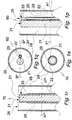
- Figs. 1a through 1g illustrate, in a more general manner, distal terminal portions of a prestage, a proto device and a device of the invention. In particular, it is shown in:
- EXAMPLE 1 General disposition of a combination of micro electrode and optical fiber in a prestage device, a proto device and a device of the invention
- Figs. 1a, 1b show axial sections of a terminal portion and a major portion including the terminal portion of a prestage device 1" of the composition.
- the multi-S-formed portion extending from the terminal portion is extendable in a distal/proximal direction.
- the terminal portion comprises a blunt distal tip 9.
- a combination 2 of optical fiber and electrode is schematically rendered.
- the combination 2 is centered in the distal and main portions.
- the terminal portion is rotationally symmetric, cf central axis B-B in Fig. 1f .
- the combination of electrode and optical fiber 2 is enclosed by a stiffening element or layer 3, which is also rotational symmetric at least in the straight distal terminal portion.
- the stiffening element 3 is of a material dissolvable in aqueous body fluid including water or degradable by the fluid or water, and is preferably of a biocompatible carbohydrate and/or proteinacious material such as glucose and albumin.
- the stiffening element 3 is of a biocompatible material gelling by contact with aqueous body fluid, such as gelatin or hyaluronic acid or a mixture of gelatin or hyaluronic acid with carbohydrate and/or proteinacious material. In a gelled state the gelling material is translucent.
- a thin layer 4 of a flexible, electrically insulating material such as parylene C is disposed on the stiffening element so as to enclose it completely.
- Fig. 1c illustrates the distal terminal portion of a proto device 1' of the invention obtained by radially cutting the prestage device 1" in plane A-A.
- Reference numbers 2, 3, 4 identify the same features as in Figs. 1a, 1b .
- a circular, flat terminal face 6 illustrated by Fig. 1g is produced.
- Fig. 1d shows a state of the proto device 1' upon insertion into soft tissue for a short period of time.
- a terminal portion of the stiffening element 3 has been dissolved or degraded or transformed to a translucent gel, the transformed portion being identified by 8.
- EXAMPLE 2 Prestage device, proto device and device of the invention comprising a first combination of micro electrode and optical fiber
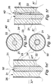
- Figs. 1h and 1i illustrate axial B ⁇ -B ⁇ and radial A ⁇ -A ⁇ sections of the distal terminal portion of a prestage device 40" comprising a first combination of micro electrode 22 and optical fiber 21.
- the fiber 21 and the electrode 22 are disposed in parallel and attached to each other by permanent adhesive bridges 25.
- the combination of optical fiber 21 and electrode 22 is enclosed by a layer or element 23 of a stiffening material.
- the optical fiber 21 has polished flat distal face 31 disposed at about the same radial level as the distal end of the electrode 22.
- the stiffening element 23 is dissolved or degraded by contact with aqueous body fluid 8 and substituted by it or is transformed into a translucent gel 28, Figs. 1l, 1m .
- a variety 40' ⁇ of the proto device 40' is shown, of which the distal face 26 is covered by a cap 27 of a water soluble material such as glucose or a mixture of glucose with lactose or gelatin.
- the function of the cap 27 is to facilitate insertion of the proto device into soft tissue and to delay contact of the electrode 22 with surrounding tissue.
- EXAMPLE 3 Prestage device, proto device and device of the invention comprising a second combination of micro electrode and optical fiber
- Figs. 1j and 1k illustrate axial B ⁇ -B ⁇ and radial A'-A", A ⁇ -A ⁇ sections of the distal terminal portion of a prestage device 50" comprising a second combination of micro electrode 22 and optical fiber 21 enclosed by a layer or element 23 of stiffening material.
- the electrode 22 has polished flat distal face 31 and is enclosed by an electrically conducting layer 22 forming an electrode.
- the distal end of the electrode layer 22 and the distal face 31 of the optical fiber 21 are disposed at the same radial level.
- the stiffening element 23 Upon insertion of the proto device 50' with its distal end foremost into soft tissue, the stiffening element 23 is dissolved or degraded by contact with aqueous body fluid 8 and substituted by it or is transformed into a translucent gel 28, Figs. 1l, 1m . Cutting the prestage device distally of the end face 31 of the optical fiber and of the electrode tip disposes the end face 31 withdrawn from the distal face 26 of the stiffening element 23 and of the distal circular rim 26 ( Fig. 11 ) of the flexible polymer coat 24, thereby preventing or at least delaying contact of the electrode 22 and the optical fiber 21 with surrounding tissue.
- a variety 50' ⁇ of the proto device 50' is shown, the distal face 26 of which is covered by a cap 27 of a water soluble material such as glucose.
- the function of the cap 27 is to facilitate insertion into soft tissue.
- EXAMPLE 4 Prestage device, proto device and device of the invention comprising a third combination of micro electrode and optical fiber
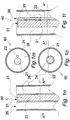
- Figs. 1p', 1q' illustrate axial B ⁇ -B ⁇ and radial A ⁇ -A ⁇ sections of the distal terminal portion of a proto device 60' of the invention, comprising a third combination of micro electrode 22 and optical fiber 21.
- the fiber 21 and the electrode 22 are disposed in parallel and attached to each other by permanent adhesive bridges 25.
- the combination of optical fiber 21 and electrode 22 is enclosed by a layer or element 23 of a stiffening material, which is in turn enclosed by a coat 24 of flexible polymer material such as Parylene C.
- the optical fiber 21 has polished flat distal face 31 disposed at about the same radial level as the distal end of the electrode 22. Except for a distal end portion the electrode 22 is electrically insulated by a lacquer coat 29.
- the proto device 60' has been produced from a corresponding prestage device (not shown) in a manner described in Examples 2 and 3.
- the stiffening element 23 Upon insertion of the proto device 60' with its distal end foremost into soft tissue, the stiffening element 23 is dissolved or degraded by contact with aqueous body fluid 8 and substituted by it or is transformed into a translucent gel 28, to form a third embodiment 60 of the device of the invention, Figs. 1p, 1q .
- EXAMPLE 5 Prestage device, proto device and device of the invention comprising a fourth combination of micro electrode and optical fiber
- Figs. 1r', 1s' illustrate axial and radial A ⁇ -A ⁇ sections of the distal terminal portion of a proto device 70' of the invention, comprising a fourth combination of micro electrode 22 and optical fiber 21.
- the combination of micro electrode 22 and optical fiber 21 is enclosed by a layer or element 23 of stiffening material.
- the optical fiber 21 has a polished flat distal face 31. It is enclosed by an electrically conducting layer 22 forming the electrode. Except for a portion 33 extending proximally from its distal end the electrode layer 22 is covered by an insulating lacquer 32.
- the lacquer 32 is disposed between the electrode layer 22 and the stiffening element 23.
- the distal end of the electrode layer 22 and the distal face 24 of the optical fiber 21 are disposed at the same radial level.
- the stiffening element 23 Upon insertion of the proto device 70' with its distal end foremost into soft tissue, the stiffening element 23 is dissolved or degraded by contact with aqueous body fluid 8 and substituted by it or is transformed into a translucent gel 28. Thereby a corresponding device 70 of the invention is formed, Figs. 1r, 1s .
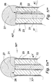
- the proto device 201' of Fig. 2 is about rotationally symmetric in respect of a central longitudinal axis D-D.
- the proto device 201' comprises, in addition to a combination of optical fiber and electrode 202, a stiffening element 203 of a water dissolvable or degradable material and a coat 204 of a flexible, water insoluble polymer material on the stiffening element 203.
- the proto device 201' is provided with a rounded cap 207 on its front end. The purpose of the cap 207 is to minimize tissue damage caused by inserting the proto device 201' into soft tissue.
- the material of the cap 207 is one that is readily dissolvable in body fluid, that is, within a couple of minutes, but which is different from water soluble material of the stiffening element 203.
- the electrode and the optical fiber are electrically and optically, respectively, connected with a control unit 230 disposed at the proximal end of the proto device 201'.
- the control unit is of the same kind as that of the following example.
- the proto device 301' of Fig. 3 is about rotationally symmetric in respect of a central longitudinal axis E-E.
- the proto device 301' comprises, in addition to a combination of optical fiber and electrode 302, a stiffening element 303 and a coat 304 of a flexible, water insoluble polymer material on the stiffening element 303.
- the proto device 301' is provided with a rounded cap 307 on its front end. The purpose of the cap 307 is to minimize tissue damage caused by inserting the proto device 301' into soft tissue.
- the material of the cap 307 is identical with the material of the stiffening element 303.
- the electrode and the optical fiber are electrically and optically, respectively, connected with a control unit 330 disposed at the proximal end of the proto device 301'.
- the control unit 330 can be of various kinds and for various purposes, such as for controlling the current and voltage of power fed to the electrode and/or for recording and/or transmitting electric signals received from the electrode and/or for emitting radiation into the optical fiber or receiving radiation emanating from the tissue through the optical fiber and detecting it.
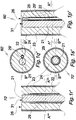
- the proto device 401' is rotationally symmetric about a central longitudinal axis J-J and comprises an optical fiber 421, an electrically conducting coat 422 forming an electrode on the fiber 421, a stiffening layer or element 423 on the electrode 422 and a second coat 424 of flexible, water insoluble polymer material on the stiffening element 423.
- a distal terminal section of the electrode layer 422 has the form of a brush 422 ⁇ of tiny metallic fibers extending in a radial direction from the layer 422 so as to provide for a large electrode tip surface. Except for the brush section 422 ⁇ the electrode 422 is insulated by a lacquer (not shown).
- the optical fiber has a distal terminal flat face 431 disposed in the same radial plane as the distal rim of the flexible polymer coat 424.
- the proto device 501' is rotationally symmetric about a central longitudinal axis K-K and comprises an optical fiber 521, an electrically conducting coat 522 forming an electrode on the fiber 521, a stiffening layer or element 523 on the electrode 522 and a coat 524 of flexible, water insoluble polymer material on the stiffening element 523.
- An electrically conducting layer 533 is provided on the flexible polymer coat 524 and is covered by a coat 524' of same material as the flexible polymer coat 524, so as to be fully enclosed by the insulating coats 524, 524'.
- the conducting layer 533 is kept on earth potential for shielding the electrode 522.
- the optical fiber 521 has a distal terminal flat face 531 disposed in the same radial plane as the distal rim of the flexible polymer coat 524.
- the proto device 601' of cylindrical form (central axis M-M) of the invention of Fig. 6 is similar to that of Fig. 1c except for the water soluble stiffening element consisting of two sections, a frontal (distal) section 603 and a proximal section 603' extending rearwards from the distal end of the frontal section 603.
- Elements 602, 604, 606 correspond functionally to elements 2, 4 and 6 of the embodiment of Fig. 1c .
- the tenth embodiment of the proto device of the invention 701' of Fig. 7 (axial section N-N) comprises a front portion functionally corresponding to that of the embodiment of Fig. 1c , elements 702, 703, 704, corresponding to elements 2, 3, and 4, respectively.
- the water soluble material of the stiffening element 703 does not extend along the entire proto device 701' but only over a portion thereof extending rearwards from its distal end.
- a bulged container 715 of polymer material through which the combination of optical fiber and electrode 702 extends centrally is joined.
- the rear end of the container 715 of a polymer material such as parylene or silicone rubber is joined to a stiff polymer tube 717 through which the combination of optical fiber and electrode 702 further extends.
- the stiff tube 717 is so dimensioned that a tubular void 718 is formed between it and the container 715.
- the container 715 is filled with a porous, water insoluble material 716, for instance silica.
- a pharmacologically active agent, such as dopamine, is adsorbed on the porous material 716.
- the proto device of Fig. 7 is transformed to the device 701 of Fig. 8 ).
- a controlled forward flow F of saline in the void 718 of tube 717 dopamine adsorbed on the porous material 716 is dissolved and diffuses into the void 708 and, from there, through the distal terminal opening 719 into adjoining tissue to exert its effect on biological structures, such as neurons, the electrical activity of which can be monitored by the electrode and which can be irradiated by radiation conducted by the optical fiber of the combination of optical fiber and electrode 702.
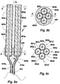
- Each of the proto devices 801a', 801b', 801c', 801d' comprises a central combination of optical fiber and electrode 802a, 802b, 802c, 802d, a water soluble stiffening element or layer 803a, 803b, 803c, 803d on each of the combinations of optical fiber and electrode 802a, 802b, 802c, 802d and a flexible water-insoluble polymer coat 804a, 804b, 804c, 804d on the corresponding stiffening element 803a, 803b, 803c, 803d.
- the proto devices 801a', 801b', 801c', 801d' are arranged symmetrically in respect of a central bundle axis Q-Q.
- Proximal sections 810a, 810c of the optical fibers and electrical conductors of the bundle are connected with a control unit (not shown).
- a bundle of proto devices of the invention can comprise two or more different proto devices of the invention.
- a corresponding bundle of devices of the invention is formed by dissolution or degradation of the water soluble or degradable stiffening elements.
- the bundle of proto devices of the invention can be incorporated into a shell of a water soluble material (not shown).
- the shell has a sharp of blunt front end and is preferably rotationally symmetric about the bundle axis Q-Q and extends to the base 820.
- the array 950 of the invention shown in Fig. 10 comprises six bundles 901'a, 902'a, 903'a, 904'a, 905'a, 906'a of proto devices of the invention. Each bundle comprises a pair of proto devices.
- Each of the bundles 900a', 900b', 900c', 900d', 900e', 900f' is mounted at its rear end in a bundling holder ( Fig. 11 ). Only the holder 911a for bundle 900a' is specifically identified in Fig. 11 .
- the bundling holders 911 are mounted by gluing on an oblong, about rectangular flat base 910 with a pointed front end 909.
- the base 910 is preferably of a biocompatible polymer material like polypropylene, polyacrylate or polycarbonate.
- the holders 911a are mounted symmetrically in respect of the long base axis U-U so that three of the bundles 900a', 900b', 900c' of proto devices are mounted at the left hand long edge 970 of the base 910 and the other three 900d', 900e', 900f' at the right hand long edge 971 in a manner so as to have front end portions of the bundles 900a', 900b', 900c', 900d', 900e', 900f' of proto devices extend over the respective edge in oblique forward directions.
- the array of proto bundles can be incorporated in a shell of a water soluble material (not shown).
- the array 950 of bundles 900a', 900b', 900c', 900d', 900e', 900f' of proto devices of the invention is transformed to a corresponding array of bundle of devices of the invention (not shown) by dissolution, degradation or swelling of their stiffening elements.
- the array 1001 of Fig. 12 comprises a thin circular flat support of polyurethane 1002 from one (top) face of which nine bundles of proto devices of the invention 1003, 1004, 1005, 1006, 1007, etc. of the invention extend perpendicularly so as to be disposed in parallel in respect of each other. Each bundle comprises five proto devices of the invention.
- the proto devices of the bundles 1003, 1004, 1005, 1006, 1007, etc. penetrate the support 1002 and extend for a short distance from its other (bottom) face. They are bundled in a flexible tube 1008 and optically and electrically connected with a control unit 1009.
- the control unit 1009 allows a person to activate optical fibers and electrodes of selected bundle(s) and even selected optical fibers and electrodes of one bundle, as well as to receive optical and electrical signals emitted from soft tissue for transmission to the control unit.
- the control unit 1009 also allows a person transmit radiation of different kind through selected optical fibers of the bundles.
- Various energizing and radiation patterns can thus be realized as well as electrical signal and radiation patterns emanating from soft tissue received and detected.
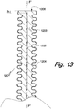
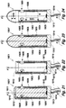
- Fig. 13 an axial section F'-F' of a distal terminal portion of a tenth embodiment 1201' of the proto device of the invention.
- Reference number 1202 identifies a combination of optical fiber and electrode, which is withdrawn in a proximal direction by a distance h from the distal face 1206 a bellows-shaped stiffening element 1203 of corresponding geometry on which a correspondingly shaped flexible polymer coat 1204 is disposed.
- the coat 1204 of device of the invention thus formed is extendible in a proximal/ distal direction, thereby is designed to adapt to movements of different portion of the tissue into which the device is inserted, and to be anchored in the tissue.
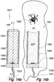
- the rotationally symmetric (central axis F-F) twelfth embodiment of the proto device 1301' of the invention illustrated in Fig. 14a comprises an LED 1309 as a light source and a cylindrical layer 1302 of gold or platinum on the inner face of a cylindrical flexible polymer coat 1302.
- a cap 1307 of a water soluble material is attached to the distal face of the coat 1304, the proximal end of which is attached to a circular base 1330.
- the coat 1304/gold layer 1308, the cap 1307 and the base 1330 define a cylindrical space occupied by a stiffening element 1303 of a water soluble mixture of glucose and albumin or gelatin selected from natural gelatin and gelatin cross linked by heat or chemically.
- the LED 1309 and the electrode layer 1302 are electrically connected with a control unit (not shown) via a multiple lead 1331.
- the stiffening element Upon insertion of the proto device 1301' into soft tissue ST the stiffening element is contacted by aqueous soft tissue fluid STF at its distal face and dissolved. A device of the invention 1301 is thereby formed, Fig. 14b . Over time the solution of glucose and albumin in the void formerly occupied by the stiffening element 1303 is substituted by pure soft tissue fluid STF or, if the stiffening element is swellable like gelatin the void becomes filled with a translucent gel. By energizing the LED a neuron 1320 disposed distally of the device 1301 is irradiated.
- the twelfth embodiment 1401' of the proto device of the invention shown in Fig. 15 corresponds to the eleventh embodiment 1301' of Fig. 14a except for the electrode being insulated except at its distal terminal portion and by a shielding metallic layer 1405 being disposed on the outer face of the flexible polymer coat 1404. On its outer face the shielding layer 1405 is covered by a coat 1406 of same material as the coat 1404 so as to be fully insulated.
- the layer 1404 shielding the electrode 1402 is kept on earth potential to protect the electrode 1402 from being disturbed by external electrical fields.
- the electrode 1402 is insulated by a lacquer 1408 at its inner face except for a small portion at 1410 extending from its distal end.
- the electrode 1402 is withdrawn in a proximal direction by a distance h from the distal faces 1411 of the stiffening element 1403 and the flexible polymer coat 1404.
- the electrode layer 1402 and the shielding layer 1405 as well as the flexible polymer layers 1404, 1406 are attached to the base 1430 and electrically connected with the multiple lead 1431 via the base 1430.
- the elements identified by reference numbers 1407 and 1409 correspond to elements 1307 and 1309, respectively, of the embodiment of Fig. 14a .
- a coat of Parylene C of about 4 ⁇ m thickness is applied by a state-of-the-art vacuum coating process (http://www.scscookson.com/parylene/properties.cfm) in which di-paraxylylene is vaporized and then pyrolized to paraxylylene, which is adduced under high vacuum to a deposition chamber kept at about room temperature and there deposited on the sucrose coated element of Example 17.
- the twice coated device thus obtained corresponds to a prestage device of the invention.
- EXAMPLE 20 Manufacture of a proto device of the invention from the prestage device of Example 18
- the prestage device of Example 18 is dipped with its front end foremost into molten high melting paraffin (m.p. of about 40 °C) in a short 3 mm diameter polypropylene cylinder. After cooling to room temperature, the paraffin block containing the prestage device is put on a polypropylene support and cut radially with a razor blade so as to sever its tip. After removing most of the paraffin by melting the block and withdrawing the proto device thus formed the latter is rinsed several times with pentane and dried. The recorded impedance of the insulated electrode body prior to cutting is >10 megohm, measured with the electrode body immersed into saline.
- molten high melting paraffin m.p. of about 40 °C
- the recorded impedance after cutting the tip and immersion of the proto device into saline for 2-3 h is ⁇ 50 kohm.
- the prestage device of Example 15 is fixed under a microscope and portions of the Parylene C coat near the front end are removed by scraping the coat with a micro file made by coating a thin steel wire (0.1 mm diameter) with titanium oxide powder (grain of about 10 ⁇ m) by means of cyanoacrylate pre-polymer dissolved in diethyl ether, into which the wire is dipped immediately prior to the application of the powder.
- Dimensions of the proto device can vary within a broad range: diameters of up to 100 ⁇ m or more are useful. A preferred diameter is from 5 ⁇ m - 30 ⁇ m.
- the length of the proto device can be adapted to its desired location after insertion.
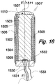
- the fourteenth embodiment 1501' of the proto device of the invention shown in Fig. 16 differs from the thirteenth embodiment 1401' by comprising, in addition to a light source 1509 mounted in basis 1530, a light sensor 1532, in particular one for fluorescent light, also mounted in basis 1530.
- the radiation sensor 1532 is electrically connected by a flexible, electrically conducting wire 1533 with a recording unit (not shown) comprising a microprocessor, a memory and a data output means such as a printer.
- the other features 15XX of the proto device 1501' correspond to respective features 14XX of the proto device 1401' of the thirteenth embodiment.
- the fifteenth embodiment 1601' of the proto device of the invention shown in Figs. 17 , 29 comprises a stiffening element 1603, which is degradable or soluble in aqueous body fluid.
- the stiffening element 1603 is mounted on a rigid cylindrical base 1613 of polymer material such as highly cross-linked polyurethane.
- An LED light source 1609 is mounted on the distal face of the base 1613 and is energized by means of an insulated flexible conductor 1614 connected to a power source.
- the stiffening element 1603 is of substantially cylindrical form a rotationally symmetric in respect of its longitudinal axis F-F.
- the stiffening element 1613 and the base 1603 have about the same diameter.
- the stiffening element 1603 is covered by consecutive layers of electrically insulating flexible polymer 1608, an electrically conducting flexible electrode layer 1604, and a flexible coat layer 1602.
- the flexible electrode layer 1604 has been attached to the insulating polymer layer 1608 and, to a narrow zone distal zone of the stiffening element 1603 not covered by the insolating polymer layer 1608 by a suitable method such as metal ion sputtering. Metals of high conductivity like gold and copper, are preferred for this purpose.
- the polymer layers 1608 and 1602 have been attached by dipping the proto device under formation in solutions of the respective polymer in an organic solvent of low polarity in which the stiffening element 1603 material is not soluble.
- the distal face 1611 of the stiffening element is then covered with a rounded cap 1610 of a material, which is readily soluble in aqueous body fluid.
- the cap 1610 is provided to facilitate insertion of the device into soft tissue.
- the electrode layer 1604 is slightly withdrawn from the distal rim of the flexible polymer coat as indicated by "h" in Fig. 17 .
- a distal terminal portion of the electrode layer 1604 is not covered by the insulating inner flexible polymer layer 1608 to provide for electrical contact with body fluid.
- distal axial opening 1615 In addition to the distal axial opening 1615 are provided three distal radial openings 1605, 1606, 1607 of circular form with their centers disposed in the same radial plane B-B.
- the radial openings are arranged to allow light to emanate in a radial direction to affect or visualize neighboring soft tissue structures.
- the inner face of the electrically insulating polymer layer 1608 can be provided with a reflective coat, such as a thin coat of silver or platinum, or by using a polymer with good visible light reflectance properties for layer 1608.
- the wide beam of visible light emitted by the light source 1609 is directed in a distal direction; a portion of it hits the inner face of the insulting polymer layer or of a reflective coat on that layer.
- Non-insulated annular portions of the electrode layer 1604 are disposed in the lateral openings, only one 1604 ⁇ of them being indicated in Figs. 17 and 18 .
- These two kinds of blank electrode faces can be used in combination. Alternatively, if only one of them is desired to be used, the other can be made inactive by applying a layer of electrically insulating material on it (not shown in the Figures).
- the proto device 1601' Upon implantation into soft tissue the proto device 1601' is transformed into a device 1601 of the invention shown in Figs. 18 , 30 by dissolution or degradation of its stiffening element.
- “M” designates the inner space of the device 1601 filled with body fluid upon complete dissolution of the stiffening element 1603.
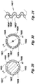
- Fig. 31 illustrates a section 1601 ⁇ of a physically modified wall of the device 1601 of the invention.
- the modification consists in providing the wall with the form of a meander or bellows form.
- the wall section 1601 ⁇ comprises a flexible polymer coat 1604 ⁇ , an electrode layer 1602 ⁇ , and an inner insulating polymer layer 1608 ⁇ .
- a device of the invention comprising or consisting of non-resilient wall materials can be made extendible in an axial direction.
- the proto device 1701' of the invention illustrated in Fig. 19 is shown in an axial view corresponding to the proto device of Fig. 17 , from which it differs by substitution of cap 1610 by a portion of its flexible polymer coat 1704.
- the stiffening element 1703 Upon implantation into soft tissue the stiffening element 1703 is dissolved or degraded and substituted by aqueous body fluid. Thereby a corresponding device 1701 of the invention illustrated in Fig. 20 is formed.
- Reference numbers 17XX in Figs. 19 and 20 not specifically addressed refer to elements of corresponding kind 16XX illustrated in Figs. 17 and 18 .
- the proto device 1801' of the invention illustrated in Fig. 21 is shown in an axial view corresponding to the proto device of Fig. 17 , from which it differs by provision of an optical sensor 1815 mounted on the distal face of the base 1813.
- the sensor 1815 is sensitive to visible light. It is particularly suited for monitoring fluorescent radiation of a certain wavelength, and is so selected from a number of commercially available light sensors. It is electrically coupled with a recording unit (not shown) by insulated flexible lead 1816.
- the recording unit can transform electrical signals from the sensor to numerical data and store these data in a memory.
- the recording unit is also capable of coordinating tissue irradiation by light source 1809, recording of sensor 1815 data, and electrode 1802 control.
- the proto device 1901' of the invention illustrated in Fig. 23 is shown in an axial view corresponding to the proto device of Fig. 17 , from which it differs by a reflective inner wall portion 1919 and a distal wall portion 1918 provided with micro openings.
- the micro openings are provided by laser technique; their function is to provide access of body fluid to the stiffening element 1903 to allow or facilitate its dissolution and the transport of its constituents out of the interior M of the device.
- the diameter of the micro openings are in the order of a 50 ⁇ m or less, more preferred from 5 ⁇ m to 30 ⁇ m.
- Reference numbers 19XX in Fig. 22 not specifically addressed refer to elements of corresponding kind 16XX illustrated in Figs. 17 and 18 .
- the proto device 1901' Upon implantation into soft tissue the proto device 1901' is transformed into a device 1901 of the invention by dissolution or degradation of its stiffening element 1903, as shown in Fig. 24 .
- EXAMPLE 26 First variety of the proto device of the invention illustrated in Fig. 17 and of a corresponding device of the invention illustrated in Fig. 18 formed from the proto device upon implantation into soft tissue.
- the proto device 2001' of the invention illustrated in Fig. 25 is shown in a sectional radial view only, which correspond to the radial view of Fig. 29 of the proto device of Fig. 17 (section B-B).
- the section B-B dissects the centers of the circular windows 2005, 2006, 2007, which are covered by portions of the flexible polymer coat 2004.
- the coat 2004 is of a translucent polymer material.
- the proto device 2001' Upon implantation into soft tissue the proto device 2001' is transformed into a device 2001 of the invention by dissolution or degradation of its stiffening element 2003, as shown in Fig. 26 .
- the void filled with body fluid is designated M.
- Reference numbers 20XX in Fig. 24 not specifically addressed refer to elements of corresponding kind 16XX illustrated in Fig. 17 .
- EXAMPLE 27 Second variety of the proto device of the invention illustrated in Fig. 17 and of a corresponding device of the invention illustrated in Fig. 18 formed from the proto device upon implantation into soft tissue.
- the proto device 2101' of the invention illustrated in Fig. 27 is shown in a sectional radial view only, which correspond to the radial view of Fig. 29 of the proto device of Fig. 17 (section B-B).
- the section B-B dissects the centers of the circular windows 2105, 2106, 2107, which are covered sheets of a translucent flexible polymer material 2115, 2116, 2117.
- the proto device 2001 Upon implantation into soft tissue the proto device 2001 is transformed into a device 2001 of the invention by dissolution or degradation of its stiffening element 2103, as shown in Fig. 28 .
- the void filled with body fluid is designated M.
- Reference numbers 21XX in Figs. 27, 28 not specifically addressed refer to elements of corresponding kind 16XX illustrated in Fig. 17 .
- the electrode is preferably of a noble metal or an alloy of noble metals or comprising noble metals such as gold, silver, platinum, iridium, but other biologically acceptable metals such as stainless steel and tantalum can also be used as well as gold plated copper.
- Aluminum is a preferred metal for coating an optical glass fiber.
- the electrical conductor may consist of or comprise an electrically conducting polymer such as PEDOT. Electrically conducting states of carbon may also be used. Portions of the electrical conductor that are not electrically insulated from tissue fluid upon removal of the first coat may be advantageously provided with surface enlarging elements or structures such as a roughened surface, forests of conducting nanowires, for instance carbon nanowires, or be porous.
- the electrical connection of the conductor with a control unit can be provided by a metal wire or similar coupled between the rear end of the electrical conductor and the control unit or by the conductor itself, a rear section thereof functioning as an electrical coupling means. In such case the rear section has to be electrically insulated.
- first coat materials which may be water dissolvable, swellable and/or degradable. If embedded in two or more of such materials they differ in their dissolution rate.
- Preferred first coat materials are water soluble carbohydrates and proteins as well as mixtures thereof. However, it is also possible to use water insoluble polymer materials swellable in water and/or degradable in body fluid.
- a suitable stiffening element coat material of which the dissolution time can be controlled is obtained by repeatedly boiling and cooling an aqueous solution of a sugar or a mixture of sugars selected from sucrose, lactose, mannose, maltose and an organic acid selected from citric acid, malic acid, phosphoric acid, tartaric acid.
- a sugar or a mixture of sugars selected from sucrose, lactose, mannose, maltose and an organic acid selected from citric acid, malic acid, phosphoric acid, tartaric acid.
- Gelatin may also be used as a first coat material. It is well known that different types of gelatin or gelatin based materials have different dissolution rates. If the first coat of water soluble or swellable material comprises two or more sections disposed along oblong combination of optical fiber/light source and electrode.
- first coat material with substantially longer dissolution times such as modified collagen, cellulose derivatives, modified starch or other biocompatible materials, such as poly-glycolic acid can also be used.
- a polymer insulating coat of the prestage device, the proto device, the bundle of proto devices and the array or proto devices and bundles of the invention or a further coat of water dissolvable material on the first coat can be covered, completely or in part, by a biocompatible gliding agent to reduce friction during insertion into tissue.
- gliding agents include glycerol monopalmitate, glycerol dipalmitate, glycerol monostearate, glycerol distearate, palmityl alcohol, stearyl alcohol.
- a thin coat of gliding agent can be applied by, for instance, spraying with a solution of the agent in ethanol or ethyl acetate.
- the dipping method should take recourse to a polymer solvent that does not interact with the water soluble/swellable/degradable material, in particular a non-polar solvent such as an alkane or alkene or cycloalkane or a non-polar aromatic solvent or a mixture thereof, in particular pentane or hexane but also diethyl ether or dichloromethane.
- Suitable polymers comprise biocompatible types of polyurethane, polyurethane urea and polyimide.
- Other useful polymers include silicones of various kind.
- Further useful polymers include polyethylene terephthalate (PET).
- PET polyethylene terephthalate
- the flexible polymer coat of the invention moves with surrounding tissue and does not restrict tissue movement. The thickness of the flexible coat is from a few ⁇ m and up to 20 ⁇ m or 50 ⁇ m or more.
- Bundles of proto electrodes Proto devices of the invention can be bundled in different ways, such as by incorporation of their rear end portions in a base of polymer or other material or by joining their rear end portions with glue.
- the bundling can be temporary, such as for keepings the devices in a fixed relationship prior to and during insertion into soft tissue, or permanent.
- a bundle of proto devices comprises a bundling means disposed in a proximal direction from the distal end of the two or more devices comprised by the bundle and aligned in parallel or about in parallel.
- the bundling means is preferably permanent, that is, is not dissolved or degraded by body fluid but may also be temporary, that is, be dissolved or degraded upon disposition of the bundle in soft tissue.
- a preferred permanent bundling means is an adhesive, in particular a cold setting polymer adhesive, such as a polyurethane or polyacrylate adhesive.
- the polymer adhesive is one not dissolvable or degradable by body fluid, except for over very long periods of more than a year or five years the adhesive is applied to the aligned proto devices at proximal portions thereof.
- a water dissolvable or degradable adhesive of corresponding properties allows the proto devices to dissociate quickly or slowly upon insertion.
- a swellable but not water soluble adhesive allows the proto devices inserted into soft tissue and the devices of the invention formed from them to be displaced in a restricted manner while an insoluble and non-swellable adhesive will restrain their movement to bending and, if designed extendable, to changes in length.
- Individual proto devices of a bundle may differ in length. For instance, a central proto device of a bundle may be longer than peripheral devices thereof to provide a central bundle point.
- the proto devices of a bundle are transformed to devices of the invention and the bundle of proto devices is thereby transformed to a bundle of devices of the invention.
- an array of proto devices or bundles of proto devices forms a proto device pattern comprising numerous proto devices and/or bundles of proto devices bundles of the invention disposed on and attached to at least one face of an electrically non conducting support.
- Thin supports of a suitable polymer like polypropylene, polyacrylate, polycarbonate and parylene C comprising substantially only two faces are preferred.
- the supports can be flat but may also be curved.
- the proto devices and/or bundles of proto devices can be mounted on one or both surfaces of the support.
- the proto devices and the bundles of proto devices attached to the support can protrude from the support at an angle, in particular an angle of from about 15° to about 75° and even up to about 90°, the angle being one included by the device or bundle of devices and its projection onto the mounting face of the support and/or at an angle of from about 15° to about 75° included by the proto device or proto device bundle long axis and a central long axis of the support.
- the support may contain pores or be semi-permeable to body fluids, that is, permeable to at least water and inorganic salts.
- the proto device, the bundle of proto devices and the array of proto devices or bundles of proto devices are transformed to a corresponding device, a bundle of devices and an array of devices of the invention.
- the support of an array of the invention can also be of a material that is soluble or degradable in soft tissue.
- Useful materials comprise those identified above as useful water soluble/swellable/degradable first coat materials.
- an array support can be equipped with a control unit, such as one comprising or consisting of an electronic chip in electric contact with the the electrical conductor(s) of individual devices.
- the control unit can comprise or be in electrical contact with a unit for electric tissue stimulation and/or signal amplifier(s) for recording electrical nerve signals.
- the array support can also be equipped with a radiation control unit, which comprises radiation emitting means such as one or more LEDs optically coupled with optical fibers of the array.
- the array support can also be equipped with light sensor(s).
Claims (31)
- Dispositif médical destiné à être inséré dans un tissu mou, ayant une extrémité distale et une extrémité proximale, comprenant :- une micro-électrode (22) ;- une micro-source de lumière (21) ;- un élément raidisseur (23) comprenant un matériau parmi :a) un matériau soluble ou dégradable dans un fluide corporel aqueux dans une quantité suffisante pour que l'élément raidisseur (23) se dissolve ou s'affaisse en contact avec un fluide corporel aqueux ;b) un matériau gonflant dans un fluide corporel aqueux pour former un gel transparent ;- un revêtement (24) en matériau polymère flexible non conducteur sur l'élément raidisseur (23), adapté pour procurer une isolation électrique, comprenant un polyuréthane de type biocompatible, un poly(uréthane-urée), un polyimide, un parylène, des polymères, y compris les silicones et le polytéréphtalate d'éthylène (PET), et évitant, ou pour le moins retardant, un contact entre l'électrode et un tissu mou lors de l'affaissement ou du gonflement de l'élément raidisseur, le revêtement présentant une ouverture distale permettant à la lumière émise par la source de lumière de sortir du dispositif lors de l'affaissement, de la dissolution ou du gonflement,- une base disposée à une extrémité arrière du dispositif.
- Dispositif selon la revendication 1, dans lequel la source de lumière (21) est un élément du groupe consistant en une DEL, un micro-laser, et une fibre optique recevant de la lumière d'une source non comprise dans le dispositif.
- Dispositif selon la revendication 1 ou 2, dans lequel la micro-électrode (22) comprend un métal, un alliage métallique ou un polymère électroconducteur.
- Dispositif selon l'une quelconque des revendications 2 ou 3, dans lequel la micro-électrode (22) comprend une tige, une couche sur la fibre optique, ou une couche sur le revêtement polymère qui fait face à l'élément raidisseur.
- Dispositif selon l'une quelconque des revendications 1 à 4, dans lequel le revêtement polymère (24) présente une forme approximativement cylindrique.
- Dispositif selon l'une quelconque des revendications 1 à 5, dans lequel l'électrode (22) est isolée électriquement, sauf une portion qui s'étend depuis son extrémité distale en direction proximale.
- Dispositif selon l'une quelconque des revendications 1 à 6, dans lequel l'électrode (22) est blindée électriquement par une couche électroconductrice sur la face externe du revêtement polymère, maintenue au potentiel de la terre.
- Dispositif selon l'une quelconque des revendications 1 à 7, dans lequel l'élément raidisseur (23) comprend un matériau glucide et/ou protéique ou est constitué d'un tel matériau.
- Dispositif selon l'une quelconque des revendications 1 à 8, comprenant une portion extensible en direction longitudinale (proximale-distale) lors de la dissolution, de la dégradation ou du gonflement de l'élément raidisseur.
- Dispositif selon la revendication 9, dans lequel la portion extensible comprend une portion du revêtement polymère (24).
- Dispositif selon la revendication 10, dans lequel ladite portion présente une forme de soufflet.
- Dispositif selon l'une quelconque des revendications 1 à 11, comprenant une unité de contrôle de microprocesseur.
- Dispositif selon l'une quelconque des revendications 1 à 12, dans lequel l'extrémité distale de l'électrode (22) est extraite de l'ouverture distale (26) en direction proximale.
- Dispositif selon l'une quelconque des revendications 1 à 13, dans lequel l'extrémité distale de la fibre optique est extraite de l'ouverture distale (26) en direction proximale.
- Dispositif selon l'une quelconque des revendications 1 à 14, dans lequel l'élément raidisseur (23) présente une forme à symétrie de rotation approximative, en particulier une forme cylindrique approximative, et comprend deux ou plusieurs sections cylindriques de différente composition disposées de manière adjacente entre elles en direction distale-proximale.
- Dispositif selon la revendication 15, dans lequel au moins une section comprend un agent actif pharmaceutique.
- Dispositif selon la revendication 16, dans lequel l'élément raidisseur (23) comprend deux sections de composition différente disposées de manière adjacente entre elles en direction radiale.
- Dispositif selon l'une quelconque des revendications 1 à 16, comprenant un réservoir rempli d'une solution d'un agent actif pharmaceutique.
- Dispositif selon l'une quelconque des revendications 1 à 18, comprenant à son extrémité arrière un moyen de communication sans fil avec une unité de contrôle externe.
- Dispositif selon l'une quelconque des revendications 1 à 19, dans lequel l'électrode (22), la source de lumière (21) et/ou le revêtement flexible (24) sont fermement attachés à la base.
- Dispositif selon l'une quelconque des revendications 1 à 20, comprenant un capteur de radiation.
- Dispositif selon la revendication 21, dans lequel le capteur de radiation est sensible à la lumière dans le spectre visible et/ou dans l'infrarouge proche.
- Dispositif selon la revendication 21 ou 22, dans lequel le capteur de radiation est monté à la base.
- Dispositif selon l'une quelconque des revendications 1 à 23, dans lequel ladite ouverture distale (26) est sélectionnée parmi une ouverture distale axiale et une ouverture distale radiale.
- Dispositif selon la revendication 24, comprenant une ouverture axiale distale (26) et une ou plusieurs ouvertures radiales distales (26).
- Dispositif selon l'une quelconque des revendications 21 à 23, dans lequel le capteur de radiation est monté sur la base.
- Dispositif selon l'une quelconque des revendications 1 à 26, dans lequel une ouverture distale (26) est recouverte par une feuille d'un matériau polymère translucide.
- Dispositif selon la revendication 27, dans lequel la feuille de matériau translucide est aussi flexible ou plus flexible que le revêtement polymère.
- Dispositif selon l'une quelconque des revendications 1 à 28, comprenant une surface de paroi interne à haute réflectance disposée à distance de la source de lumière (21).
- Dispositif selon l'une quelconque des revendications 1 à 29, comprenant une section de paroi distale comportant des micro-ouvertures traversantes.
- Dispositif selon la revendication 30, dans lequel le diamètre de la majorité des micro-ouvertures traversantes est compris entre 5 µm et 50 µm, et en particulier entre 3 µm et 30 µm.
Applications Claiming Priority (2)
| Application Number | Priority Date | Filing Date | Title |
|---|---|---|---|
| SE1300786 | 2013-12-20 | ||
| PCT/SE2014/000152 WO2015094076A1 (fr) | 2013-12-20 | 2014-12-18 | Dispositif médical comprenant une électrode et une source de lumière |
Publications (3)
| Publication Number | Publication Date |
|---|---|
| EP3107620A1 EP3107620A1 (fr) | 2016-12-28 |
| EP3107620A4 EP3107620A4 (fr) | 2017-12-20 |
| EP3107620B1 true EP3107620B1 (fr) | 2021-09-29 |
Family
ID=53403235
Family Applications (1)
| Application Number | Title | Priority Date | Filing Date |
|---|---|---|---|
| EP14872766.2A Active EP3107620B1 (fr) | 2013-12-20 | 2014-12-18 | Dispositif médical comprenant une électrode et une source de lumière |
Country Status (11)
| Country | Link |
|---|---|
| US (1) | US11583233B2 (fr) |
| EP (1) | EP3107620B1 (fr) |
| JP (2) | JP6449301B2 (fr) |
| KR (1) | KR102377409B1 (fr) |
| CN (1) | CN106029161B (fr) |
| AU (1) | AU2014367306C1 (fr) |
| CA (1) | CA2934504C (fr) |
| EA (1) | EA032712B1 (fr) |
| IL (1) | IL246157B (fr) |
| SG (1) | SG11201604774PA (fr) |
| WO (1) | WO2015094076A1 (fr) |
Families Citing this family (15)
| Publication number | Priority date | Publication date | Assignee | Title |
|---|---|---|---|---|
| FR3045391B1 (fr) * | 2015-12-17 | 2019-09-06 | Commissariat A L'energie Atomique Et Aux Energies Alternatives | Dispositif implantable pour la stimulation optique du cerveau |
| JP7006941B2 (ja) * | 2016-02-26 | 2022-01-24 | ニューロナノ アーベー | 細胞凝集体及び組織片の移植の方法 |
| CN106178271B (zh) * | 2016-07-05 | 2019-05-24 | 上海交通大学 | Led光刺激和电记录集成的柔性神经电极器件及其制备方法 |
| US20180264191A1 (en) * | 2017-03-14 | 2018-09-20 | Massachusetts Institute Of Technology | Systems and methods for neural drug delivery and modulation of brain activity |
| CN110678222A (zh) * | 2017-05-23 | 2020-01-10 | 神经毫微股份公司 | 用于插入神经组织的器件 |
| KR101984813B1 (ko) * | 2017-06-21 | 2019-05-31 | 한국과학기술원 | 광센서를 포함하는 탄소나노튜브 기반의 x-선 튜브를 이용한 켈로이드 및 피부암 치료용 x-선 근접 치료 장치에 사용되는 초소형 x-선 튜브 시스템 및 이를 포함하는 x-선 근접 치료 시스템 |
| US10874876B2 (en) | 2018-01-26 | 2020-12-29 | International Business Machines Corporation | Multiple light sources integrated in a neural probe for multi-wavelength activation |
| US20220110567A1 (en) * | 2019-01-04 | 2022-04-14 | Neuronano Ab | Probe for implantation into nervous tissue comprising a microelectrode or a set of microelectrodes |
| CN110231682B (zh) * | 2019-05-09 | 2021-07-27 | 上海大学 | 一种用于神经活动调控的光电光纤及制作方法 |
| JP2023531516A (ja) * | 2020-07-03 | 2023-07-24 | ニューロナノ アーベー | 軟組織に挿入するための微小電極 |
| WO2022060837A1 (fr) * | 2020-09-15 | 2022-03-24 | Murata Manufacturing Co., Ltd. | Structure d'électrode de tranchée pour la mesure de biosignal |
| CN112933419B (zh) * | 2021-01-28 | 2022-09-30 | 重庆大学附属肿瘤医院 | 一种多功能医疗护理灯 |
| WO2023132778A1 (fr) * | 2022-01-05 | 2023-07-13 | Neuronano Ab | Microélectrode à insérer dans un tissu mou |
| WO2024044048A1 (fr) * | 2022-08-22 | 2024-02-29 | Boston Scientific Neuromodulation Corporation | Systèmes de photobiomodulation comprenant une électrode disposée sur ou tout prés un émetteur de lumière et procédés de fabrication et d'utilisation |
| CN117338427B (zh) * | 2023-12-05 | 2024-02-27 | 四川大学华西医院 | 一种光动力介入式导管端部定位系统及方法 |
Family Cites Families (23)
| Publication number | Priority date | Publication date | Assignee | Title |
|---|---|---|---|---|
| JPS6331678A (ja) * | 1986-07-25 | 1988-02-10 | 学校法人近畿大学 | 病変部の光凝固装置 |
| EP1339361B1 (fr) * | 2000-11-29 | 2011-08-03 | Cochlear Limited | Ensemble d'electrodes d'implant cochleaire prealablement recourbees |
| US8623012B2 (en) * | 2001-08-15 | 2014-01-07 | Nuortho Surgical, Inc. | Electrosurgical plenum |
| US20030216622A1 (en) * | 2002-04-25 | 2003-11-20 | Gavriel Meron | Device and method for orienting a device in vivo |
| JP5312018B2 (ja) * | 2005-04-05 | 2013-10-09 | エリクシアー メディカル コーポレイション | 分解性の移植可能な医療装置 |
| US8401650B2 (en) * | 2008-04-10 | 2013-03-19 | Electrocore Llc | Methods and apparatus for electrical treatment using balloon and electrode |
| US9226648B2 (en) * | 2006-12-21 | 2016-01-05 | Intuitive Surgical Operations, Inc. | Off-axis visualization systems |
| US8577447B2 (en) | 2007-05-01 | 2013-11-05 | St. Jude Medical, Atrial Fibrillation Division, Inc. | Optic-based contact sensing assembly and system |
| US9521955B2 (en) | 2007-05-03 | 2016-12-20 | Cornell Research Foundtion, Inc. | Subdural electro-optical sensor |
| AU2008336322B2 (en) * | 2007-12-10 | 2013-02-14 | Neuronano Ab | Medical electrode, electrode bundle and electrode bundle array |
| WO2009098061A1 (fr) | 2008-02-07 | 2009-08-13 | Boehringer Ingelheim International Gmbh | Hétérocycles spirocycliques, médicaments contenant ces composés, leur utilisation et procédé pour les produire |
| CA2764960C (fr) * | 2009-06-09 | 2017-07-18 | Neuronano Ab | Microelectrode et jeux de microelectrodes |
| WO2011034939A1 (fr) * | 2009-09-15 | 2011-03-24 | Rush University Medical Center | Transpondeur à nanotubes de carbone libérant de l'énergie et son procédé d'utilisation |
| WO2011057137A1 (fr) | 2009-11-05 | 2011-05-12 | Neuronexus Technologies | Dispositif d'interface neuronale à guide d'ondes |
| US20110237871A1 (en) | 2010-03-25 | 2011-09-29 | Allergan, Inc. | Controller support apparatus |
| US8442614B2 (en) | 2010-06-21 | 2013-05-14 | Alfred E. Mann Foundation For Scientific Research | Stiffness enhanced filaments |
| CN103153392B (zh) * | 2010-08-25 | 2016-03-09 | 神经毫微股份公司 | 抗位移微电极、微电极束、和微电极阵列 |
| KR101304338B1 (ko) | 2010-10-21 | 2013-09-11 | 주식회사 엠아이텍 | 액정폴리머 기반의 전광극 신경 인터페이스 및 그 제조 방법 |
| WO2012170340A2 (fr) | 2011-06-04 | 2012-12-13 | The Regents Of The University Of Michigan | Sonde neuronale pouvant être introduite ayant une structure flexible |
| WO2013016391A1 (fr) * | 2011-07-25 | 2013-01-31 | Neuronexus Technologies, Inc. | Système de transfection à neuromodulation avec amenée de fluide actif |
| EP2782636B1 (fr) * | 2011-11-24 | 2017-12-13 | Saluda Medical Pty Limited | Revêtements pour des dispositifs médicaux implantables actifs |
| EP2863990B1 (fr) * | 2012-06-21 | 2017-08-09 | Neuronano AB | Microélectrode médicale |
| SE537219C2 (sv) | 2013-03-15 | 2015-03-03 | Karin Wårdell | Kombinationsprob för lokalisering, registrering och operativstimulering av en målvävnad |
-
2014
- 2014-12-18 SG SG11201604774PA patent/SG11201604774PA/en unknown
- 2014-12-18 KR KR1020167019885A patent/KR102377409B1/ko active IP Right Grant
- 2014-12-18 CA CA2934504A patent/CA2934504C/fr active Active
- 2014-12-18 EA EA201691295A patent/EA032712B1/ru not_active IP Right Cessation
- 2014-12-18 AU AU2014367306A patent/AU2014367306C1/en active Active
- 2014-12-18 US US15/106,688 patent/US11583233B2/en active Active
- 2014-12-18 IL IL246157A patent/IL246157B/en unknown
- 2014-12-18 EP EP14872766.2A patent/EP3107620B1/fr active Active
- 2014-12-18 WO PCT/SE2014/000152 patent/WO2015094076A1/fr active Application Filing
- 2014-12-18 JP JP2016541539A patent/JP6449301B2/ja active Active
- 2014-12-18 CN CN201480076132.0A patent/CN106029161B/zh active Active
-
2017
- 2017-10-31 JP JP2017210498A patent/JP6676600B2/ja active Active
Also Published As
| Publication number | Publication date |
|---|---|
| CA2934504C (fr) | 2023-04-11 |
| IL246157A0 (en) | 2016-07-31 |
| KR20160100400A (ko) | 2016-08-23 |
| WO2015094076A1 (fr) | 2015-06-25 |
| EA032712B1 (ru) | 2019-07-31 |
| KR102377409B1 (ko) | 2022-03-21 |
| US11583233B2 (en) | 2023-02-21 |
| CN106029161A (zh) | 2016-10-12 |
| SG11201604774PA (en) | 2016-07-28 |
| CN106029161B (zh) | 2019-09-03 |
| AU2014367306B2 (en) | 2017-03-16 |
| IL246157B (en) | 2022-08-01 |
| JP2017500132A (ja) | 2017-01-05 |
| JP2018038840A (ja) | 2018-03-15 |
| CA2934504A1 (fr) | 2015-06-25 |
| US20170000419A1 (en) | 2017-01-05 |
| EP3107620A4 (fr) | 2017-12-20 |
| AU2014367306C1 (en) | 2019-05-02 |
| AU2014367306A1 (en) | 2016-06-23 |
| EA201691295A1 (ru) | 2016-10-31 |
| JP6449301B2 (ja) | 2019-01-16 |
| EP3107620A1 (fr) | 2016-12-28 |
| JP6676600B2 (ja) | 2020-04-08 |
Similar Documents
| Publication | Publication Date | Title |
|---|---|---|
| EP3107620B1 (fr) | Dispositif médical comprenant une électrode et une source de lumière | |
| US11090483B2 (en) | Medical microelectrode, method for its manufacture, and use thereof | |
| KR101526288B1 (ko) | 의료용 전극, 전극 다발, 및 전극 다발 어레이 | |
| EP2117426B1 (fr) | Réseau d'électrode | |
| Knisley et al. | Simultaneous electrical and optical mapping in rabbit hearts |
Legal Events
| Date | Code | Title | Description |
|---|---|---|---|
| STAA | Information on the status of an ep patent application or granted ep patent |
Free format text: STATUS: THE INTERNATIONAL PUBLICATION HAS BEEN MADE |
|
| PUAI | Public reference made under article 153(3) epc to a published international application that has entered the european phase |
Free format text: ORIGINAL CODE: 0009012 |
|
| STAA | Information on the status of an ep patent application or granted ep patent |
Free format text: STATUS: REQUEST FOR EXAMINATION WAS MADE |
|
| 17P | Request for examination filed |
Effective date: 20160712 |
|
| AK | Designated contracting states |
Kind code of ref document: A1 Designated state(s): AL AT BE BG CH CY CZ DE DK EE ES FI FR GB GR HR HU IE IS IT LI LT LU LV MC MK MT NL NO PL PT RO RS SE SI SK SM TR |
|
| AX | Request for extension of the european patent |
Extension state: BA ME |
|
| DAX | Request for extension of the european patent (deleted) | ||
| A4 | Supplementary search report drawn up and despatched |
Effective date: 20171117 |
|
| RIC1 | Information provided on ipc code assigned before grant |
Ipc: A61N 1/05 20060101AFI20171113BHEP Ipc: A61B 5/04 20060101ALI20171113BHEP Ipc: A61N 1/14 20060101ALI20171113BHEP Ipc: A61N 5/06 20060101ALI20171113BHEP |
|
| RIC1 | Information provided on ipc code assigned before grant |
Ipc: A61N 1/05 20060101AFI20210217BHEP Ipc: A61N 5/06 20060101ALI20210217BHEP Ipc: A61B 5/00 20060101ALI20210217BHEP Ipc: A61N 1/14 20060101ALI20210217BHEP |
|
| RAP3 | Party data changed (applicant data changed or rights of an application transferred) |
Owner name: NEURONANO AB |
|
| RIN1 | Information on inventor provided before grant (corrected) |
Inventor name: SCHOUENBORG, JENS |
|
| GRAP | Despatch of communication of intention to grant a patent |
Free format text: ORIGINAL CODE: EPIDOSNIGR1 |
|
| STAA | Information on the status of an ep patent application or granted ep patent |
Free format text: STATUS: GRANT OF PATENT IS INTENDED |
|
| INTG | Intention to grant announced |
Effective date: 20210422 |
|
| GRAS | Grant fee paid |
Free format text: ORIGINAL CODE: EPIDOSNIGR3 |
|
| GRAA | (expected) grant |
Free format text: ORIGINAL CODE: 0009210 |
|
| STAA | Information on the status of an ep patent application or granted ep patent |
Free format text: STATUS: THE PATENT HAS BEEN GRANTED |
|
| AK | Designated contracting states |
Kind code of ref document: B1 Designated state(s): AL AT BE BG CH CY CZ DE DK EE ES FI FR GB GR HR HU IE IS IT LI LT LU LV MC MK MT NL NO PL PT RO RS SE SI SK SM TR |
|
| REG | Reference to a national code |
Ref country code: GB Ref legal event code: FG4D |
|
| REG | Reference to a national code |
Ref country code: CH Ref legal event code: EP Ref country code: AT Ref legal event code: REF Ref document number: 1433675 Country of ref document: AT Kind code of ref document: T Effective date: 20211015 |
|
| REG | Reference to a national code |
Ref country code: DE Ref legal event code: R096 Ref document number: 602014080438 Country of ref document: DE |
|
| REG | Reference to a national code |
Ref country code: IE Ref legal event code: FG4D |
|
| REG | Reference to a national code |
Ref country code: LT Ref legal event code: MG9D |
|
| PG25 | Lapsed in a contracting state [announced via postgrant information from national office to epo] |
Ref country code: LT Free format text: LAPSE BECAUSE OF FAILURE TO SUBMIT A TRANSLATION OF THE DESCRIPTION OR TO PAY THE FEE WITHIN THE PRESCRIBED TIME-LIMIT Effective date: 20210929 Ref country code: BG Free format text: LAPSE BECAUSE OF FAILURE TO SUBMIT A TRANSLATION OF THE DESCRIPTION OR TO PAY THE FEE WITHIN THE PRESCRIBED TIME-LIMIT Effective date: 20211229 Ref country code: FI Free format text: LAPSE BECAUSE OF FAILURE TO SUBMIT A TRANSLATION OF THE DESCRIPTION OR TO PAY THE FEE WITHIN THE PRESCRIBED TIME-LIMIT Effective date: 20210929 Ref country code: NO Free format text: LAPSE BECAUSE OF FAILURE TO SUBMIT A TRANSLATION OF THE DESCRIPTION OR TO PAY THE FEE WITHIN THE PRESCRIBED TIME-LIMIT Effective date: 20211229 Ref country code: HR Free format text: LAPSE BECAUSE OF FAILURE TO SUBMIT A TRANSLATION OF THE DESCRIPTION OR TO PAY THE FEE WITHIN THE PRESCRIBED TIME-LIMIT Effective date: 20210929 Ref country code: RS Free format text: LAPSE BECAUSE OF FAILURE TO SUBMIT A TRANSLATION OF THE DESCRIPTION OR TO PAY THE FEE WITHIN THE PRESCRIBED TIME-LIMIT Effective date: 20210929 Ref country code: SE Free format text: LAPSE BECAUSE OF FAILURE TO SUBMIT A TRANSLATION OF THE DESCRIPTION OR TO PAY THE FEE WITHIN THE PRESCRIBED TIME-LIMIT Effective date: 20210929 |
|
| REG | Reference to a national code |
Ref country code: NL Ref legal event code: MP Effective date: 20210929 |
|
| REG | Reference to a national code |
Ref country code: AT Ref legal event code: MK05 Ref document number: 1433675 Country of ref document: AT Kind code of ref document: T Effective date: 20210929 |
|
| PG25 | Lapsed in a contracting state [announced via postgrant information from national office to epo] |
Ref country code: LV Free format text: LAPSE BECAUSE OF FAILURE TO SUBMIT A TRANSLATION OF THE DESCRIPTION OR TO PAY THE FEE WITHIN THE PRESCRIBED TIME-LIMIT Effective date: 20210929 Ref country code: GR Free format text: LAPSE BECAUSE OF FAILURE TO SUBMIT A TRANSLATION OF THE DESCRIPTION OR TO PAY THE FEE WITHIN THE PRESCRIBED TIME-LIMIT Effective date: 20211230 |
|
| PG25 | Lapsed in a contracting state [announced via postgrant information from national office to epo] |
Ref country code: AT Free format text: LAPSE BECAUSE OF FAILURE TO SUBMIT A TRANSLATION OF THE DESCRIPTION OR TO PAY THE FEE WITHIN THE PRESCRIBED TIME-LIMIT Effective date: 20210929 |
|
| PG25 | Lapsed in a contracting state [announced via postgrant information from national office to epo] |
Ref country code: IS Free format text: LAPSE BECAUSE OF FAILURE TO SUBMIT A TRANSLATION OF THE DESCRIPTION OR TO PAY THE FEE WITHIN THE PRESCRIBED TIME-LIMIT Effective date: 20220129 Ref country code: SK Free format text: LAPSE BECAUSE OF FAILURE TO SUBMIT A TRANSLATION OF THE DESCRIPTION OR TO PAY THE FEE WITHIN THE PRESCRIBED TIME-LIMIT Effective date: 20210929 Ref country code: RO Free format text: LAPSE BECAUSE OF FAILURE TO SUBMIT A TRANSLATION OF THE DESCRIPTION OR TO PAY THE FEE WITHIN THE PRESCRIBED TIME-LIMIT Effective date: 20210929 Ref country code: PT Free format text: LAPSE BECAUSE OF FAILURE TO SUBMIT A TRANSLATION OF THE DESCRIPTION OR TO PAY THE FEE WITHIN THE PRESCRIBED TIME-LIMIT Effective date: 20220131 Ref country code: PL Free format text: LAPSE BECAUSE OF FAILURE TO SUBMIT A TRANSLATION OF THE DESCRIPTION OR TO PAY THE FEE WITHIN THE PRESCRIBED TIME-LIMIT Effective date: 20210929 Ref country code: NL Free format text: LAPSE BECAUSE OF FAILURE TO SUBMIT A TRANSLATION OF THE DESCRIPTION OR TO PAY THE FEE WITHIN THE PRESCRIBED TIME-LIMIT Effective date: 20210929 Ref country code: ES Free format text: LAPSE BECAUSE OF FAILURE TO SUBMIT A TRANSLATION OF THE DESCRIPTION OR TO PAY THE FEE WITHIN THE PRESCRIBED TIME-LIMIT Effective date: 20210929 Ref country code: EE Free format text: LAPSE BECAUSE OF FAILURE TO SUBMIT A TRANSLATION OF THE DESCRIPTION OR TO PAY THE FEE WITHIN THE PRESCRIBED TIME-LIMIT Effective date: 20210929 Ref country code: CZ Free format text: LAPSE BECAUSE OF FAILURE TO SUBMIT A TRANSLATION OF THE DESCRIPTION OR TO PAY THE FEE WITHIN THE PRESCRIBED TIME-LIMIT Effective date: 20210929 Ref country code: AL Free format text: LAPSE BECAUSE OF FAILURE TO SUBMIT A TRANSLATION OF THE DESCRIPTION OR TO PAY THE FEE WITHIN THE PRESCRIBED TIME-LIMIT Effective date: 20210929 |
|
| REG | Reference to a national code |
Ref country code: DE Ref legal event code: R097 Ref document number: 602014080438 Country of ref document: DE |
|
| PG25 | Lapsed in a contracting state [announced via postgrant information from national office to epo] |
Ref country code: MC Free format text: LAPSE BECAUSE OF FAILURE TO SUBMIT A TRANSLATION OF THE DESCRIPTION OR TO PAY THE FEE WITHIN THE PRESCRIBED TIME-LIMIT Effective date: 20210929 Ref country code: DK Free format text: LAPSE BECAUSE OF FAILURE TO SUBMIT A TRANSLATION OF THE DESCRIPTION OR TO PAY THE FEE WITHIN THE PRESCRIBED TIME-LIMIT Effective date: 20210929 |
|
| PLBE | No opposition filed within time limit |
Free format text: ORIGINAL CODE: 0009261 |
|
| STAA | Information on the status of an ep patent application or granted ep patent |
Free format text: STATUS: NO OPPOSITION FILED WITHIN TIME LIMIT |
|
| 26N | No opposition filed |
Effective date: 20220630 |
|
| REG | Reference to a national code |
Ref country code: BE Ref legal event code: MM Effective date: 20211231 |
|
| PG25 | Lapsed in a contracting state [announced via postgrant information from national office to epo] |
Ref country code: LU Free format text: LAPSE BECAUSE OF NON-PAYMENT OF DUE FEES Effective date: 20211218 Ref country code: IE Free format text: LAPSE BECAUSE OF NON-PAYMENT OF DUE FEES Effective date: 20211218 |
|
| PG25 | Lapsed in a contracting state [announced via postgrant information from national office to epo] |
Ref country code: SI Free format text: LAPSE BECAUSE OF FAILURE TO SUBMIT A TRANSLATION OF THE DESCRIPTION OR TO PAY THE FEE WITHIN THE PRESCRIBED TIME-LIMIT Effective date: 20210929 Ref country code: BE Free format text: LAPSE BECAUSE OF NON-PAYMENT OF DUE FEES Effective date: 20211231 |
|
| PG25 | Lapsed in a contracting state [announced via postgrant information from national office to epo] |
Ref country code: IT Free format text: LAPSE BECAUSE OF FAILURE TO SUBMIT A TRANSLATION OF THE DESCRIPTION OR TO PAY THE FEE WITHIN THE PRESCRIBED TIME-LIMIT Effective date: 20210929 |
|
| PGFP | Annual fee paid to national office [announced via postgrant information from national office to epo] |
Ref country code: CH Payment date: 20230101 Year of fee payment: 9 |
|
| PG25 | Lapsed in a contracting state [announced via postgrant information from national office to epo] |
Ref country code: HU Free format text: LAPSE BECAUSE OF FAILURE TO SUBMIT A TRANSLATION OF THE DESCRIPTION OR TO PAY THE FEE WITHIN THE PRESCRIBED TIME-LIMIT; INVALID AB INITIO Effective date: 20141218 |
|
| PG25 | Lapsed in a contracting state [announced via postgrant information from national office to epo] |
Ref country code: CY Free format text: LAPSE BECAUSE OF FAILURE TO SUBMIT A TRANSLATION OF THE DESCRIPTION OR TO PAY THE FEE WITHIN THE PRESCRIBED TIME-LIMIT Effective date: 20210929 |
|
| PG25 | Lapsed in a contracting state [announced via postgrant information from national office to epo] |
Ref country code: SM Free format text: LAPSE BECAUSE OF FAILURE TO SUBMIT A TRANSLATION OF THE DESCRIPTION OR TO PAY THE FEE WITHIN THE PRESCRIBED TIME-LIMIT Effective date: 20210929 |
|
| PGFP | Annual fee paid to national office [announced via postgrant information from national office to epo] |
Ref country code: FR Payment date: 20230914 Year of fee payment: 10 |
|
| PGFP | Annual fee paid to national office [announced via postgrant information from national office to epo] |
Ref country code: GB Payment date: 20231002 Year of fee payment: 10 |
|
| PGFP | Annual fee paid to national office [announced via postgrant information from national office to epo] |
Ref country code: DE Payment date: 20231130 Year of fee payment: 10 |
|
| PG25 | Lapsed in a contracting state [announced via postgrant information from national office to epo] |
Ref country code: MK Free format text: LAPSE BECAUSE OF FAILURE TO SUBMIT A TRANSLATION OF THE DESCRIPTION OR TO PAY THE FEE WITHIN THE PRESCRIBED TIME-LIMIT Effective date: 20210929 |
|
| PGFP | Annual fee paid to national office [announced via postgrant information from national office to epo] |
Ref country code: CH Payment date: 20240102 Year of fee payment: 10 |