EP3107505B1 - Stent placement device - Google Patents
Stent placement device Download PDFInfo
- Publication number
- EP3107505B1 EP3107505B1 EP15705080.8A EP15705080A EP3107505B1 EP 3107505 B1 EP3107505 B1 EP 3107505B1 EP 15705080 A EP15705080 A EP 15705080A EP 3107505 B1 EP3107505 B1 EP 3107505B1
- Authority
- EP
- European Patent Office
- Prior art keywords
- stent
- engagement
- displacement
- engagement member
- members
- Prior art date
- Legal status (The legal status is an assumption and is not a legal conclusion. Google has not performed a legal analysis and makes no representation as to the accuracy of the status listed.)
- Active
Links
Images
Classifications
-
- A—HUMAN NECESSITIES
- A61—MEDICAL OR VETERINARY SCIENCE; HYGIENE
- A61F—FILTERS IMPLANTABLE INTO BLOOD VESSELS; PROSTHESES; DEVICES PROVIDING PATENCY TO, OR PREVENTING COLLAPSING OF, TUBULAR STRUCTURES OF THE BODY, e.g. STENTS; ORTHOPAEDIC, NURSING OR CONTRACEPTIVE DEVICES; FOMENTATION; TREATMENT OR PROTECTION OF EYES OR EARS; BANDAGES, DRESSINGS OR ABSORBENT PADS; FIRST-AID KITS
- A61F2/00—Filters implantable into blood vessels; Prostheses, i.e. artificial substitutes or replacements for parts of the body; Appliances for connecting them with the body; Devices providing patency to, or preventing collapsing of, tubular structures of the body, e.g. stents
- A61F2/95—Instruments specially adapted for placement or removal of stents or stent-grafts
- A61F2/962—Instruments specially adapted for placement or removal of stents or stent-grafts having an outer sleeve
- A61F2/966—Instruments specially adapted for placement or removal of stents or stent-grafts having an outer sleeve with relative longitudinal movement between outer sleeve and prosthesis, e.g. using a push rod
-
- A—HUMAN NECESSITIES
- A61—MEDICAL OR VETERINARY SCIENCE; HYGIENE
- A61F—FILTERS IMPLANTABLE INTO BLOOD VESSELS; PROSTHESES; DEVICES PROVIDING PATENCY TO, OR PREVENTING COLLAPSING OF, TUBULAR STRUCTURES OF THE BODY, e.g. STENTS; ORTHOPAEDIC, NURSING OR CONTRACEPTIVE DEVICES; FOMENTATION; TREATMENT OR PROTECTION OF EYES OR EARS; BANDAGES, DRESSINGS OR ABSORBENT PADS; FIRST-AID KITS
- A61F2/00—Filters implantable into blood vessels; Prostheses, i.e. artificial substitutes or replacements for parts of the body; Appliances for connecting them with the body; Devices providing patency to, or preventing collapsing of, tubular structures of the body, e.g. stents
- A61F2/95—Instruments specially adapted for placement or removal of stents or stent-grafts
- A61F2/9517—Instruments specially adapted for placement or removal of stents or stent-grafts handle assemblies therefor
Definitions
- the invention relates to a stent placement device that is configured to facilitate precise deployment of a stent into a human or animal body.
- Stents Medical endoprostheses, commonly referred to as stents, have been widely used for minimum-invasive treatment of diseased blood vessels. Stents may be used to keep a blood vessel open, for example, or may redirect flow away from an aneurysm.
- Self-expanding stents may be mechanically compressed springs which expand when released.
- Such stents may be constructed from shape-memory materials such as Nitinol.
- Stents used in the vascular system may be implanted transluminally during or following percutaneous transluminal angioplasty. The stents may be inserted into the vessel, positioned across the treatment area and then allowed to self-expand.
- a known catheter assembly for delivering a self-expanding stent consists of an outer holding catheter in which the stent is loaded at a tip.
- the holding catheter may be provided to prevent premature expansion at body temperatures for heat induced shape memory stents or to contain mechanically restrained or stress induced shape memory stents.
- An inner stopper may be placed coaxially with the stent in the outer holding catheter to prevent the stent from moving in the proximal direction (longitudinally towards the operator of the stent) when deployed. Upon deployment, the inner stopper is held steady (for example via a connecting wire) and the holding catheter is pulled back to unsheath the stent. This procedure requires a surgeon to operate double handedly, and it is challenging to synchronize the movement of both hands to achieve a precise placement of a stent. A high level of skill and experience is needed for this operation.
- US 6,786,918 B1 discloses a stent placement device in which a handle is provided with a slot and a knob that can move longitudinally within the slot.
- the knob is coupled to an outer holding catheter such that movement of the knob imparts movement to the outer holding catheter.
- the device allows a surgeon to deploy a stent one handedly.
- the arrangement is complex and requires extensive adaptation of the outer holding catheter and inner stopper relative to standard arrangements that are configured for two handed operation.
- US 2012/185031 A1 refers to a stent delivery system that includes an elongate shaft including a proximal portion, a distal portion, a lumen extending at least partially therethrough, and a stent-receiving portion on the distal shaft portion.
- the system also includes a stent positioned at the stent-receiving portion of the elongate shaft, the stent having a constrained configuration and an expanded configuration.
- Proximal and distal constraining members releasably connected to the stent and having a first position and a second position are also included.
- the proximal and distal constraining members cooperatively apply longitudinal tensile force to at least a portion of the stent with the proximal and distal constraining members each in the first position.
- a drive system configured to simultaneously move the proximal and distal constraining members is provided, including a threaded drive shaft in mechanical communication with a rotatable handle.
- An object of the present invention is to provide a stent placement device which can be operated more easily, for example with less need for skill and/or experience, which allows more precise and reliable placement of the stent, and/or which can be applied to existing stent placement apparatuses within minimal adaptation.
- a stent placement assembly comprising: a holding catheter comprising a longitudinal lumen for receiving a stent, and an output orifice at a distal end; a stopper member positioned within said lumen and moveable longitudinally relative thereto, the stopper member being configured to engage with the stent in order to restrict movement of the stent in a proximal direction; a first anchor member coupled to the holding catheter at a proximal end thereof; a second anchor member coupled to the stopper member at a proximal end thereof; and a displacement device comprising a first engagement member and a second engagement member, the first and second engagement members being configured to engage respectively with the first and second anchor members in such a way that displacement of the first engagement member relative to the second engagement member causes a corresponding displacement between the first and second anchor members, wherein: the displacement device further comprises: a handle rigidly connected to one of the first and second engagement members and a user actuatable displacement mechanism configured to be actu
- an arrangement which facilitates accurate and reliable placement of a stent by a surgeon.
- the present invention is an improvement because it can be operated using a single hand.
- the present invention provides a mechanically simpler solution and one which can be easily disengaged from the catheter assembly.
- minimal adaptation is needed to established catheter assemblies for stent deployment.
- the displacement device is configured to allow the engagement with the catheter assembly to be detachable. This facilitates use of the stent placement assembly by a surgeon because it is not necessary to have the displacement device present when it is not needed.
- a movement transducer for transforming movement of an actuator member imparted by a user into a movement of the first or second engagement member.
- the movement transducer may optionally be such as to cause the movement of the actuator member to be different from the corresponding movement of the first and second engagement members. This can improve flexibility of the device and makes it easier for the surgeon to deploy the stent precisely and/or quickly, according to the application in question.
- the movement transducer may also improve the ergonomic qualities of the stent placement assembly by obviating the need for the movement of the actuator member to be parallel with the axis of the catheter assembly and/or of the same magnitude as the desired movement between the holding catheter and the stopper member.
- a kit for facilitating operation of a catheter assembly for deploying a stent that comprises a holding catheter comprising a longitudinal lumen for receiving the stent, the holding catheter having an output orifice at a distal end, and a stopper member positioned within said lumen and movable longitudinally relative thereto, the stopper member being configured to engage with the stent in order to restrict movement of the stent in a proximal direction
- a displacement device for facilitating operation of a catheter assembly for deploying a stent
- the catheter assembly comprising a holding catheter comprising a longitudinal lumen for receiving the stent, the holding catheter having an output orifice at a distal end, and a stopper member positioned within said lumen and moveable longitudinally relative thereto, the stopper member being configured to engage with the stent in order to restrict movement of the stent in a proximal direction, a first anchor member coupled to the holding catheter at a proximal end thereof, and a second anchor member coupled to the stopper member at a proximal end thereof
- the displacement device comprises: a first engagement member and a second engagement member, the first and second engagement members being configured to engage respectively with the first and second anchor members in such a way that displacement of the first engagement member relative to the second engagement member causes a corresponding displacement between the first and second anchor members; and a handle rigidly connected to one of the first and second engagement members and a user actu
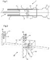
- Figure 1 is schematic sectional side view of a catheter assembly 1 for deploying a stent 6 within a human or animal body.
- the stent 6 has a substantially cylindrical form.
- the stent 6 is a self-expanding stent.
- the stent may be housed within the catheter assembly 1 in a radially constrained state and expands into a radially extended state when unsheathed or released from the catheter assembly 1.
- the stent 6 is a flow diverter stent.
- the stent may be configured to perform other functions, such as keeping a blood vessel open.
- the catheter assembly 1 comprises a holding catheter 2.
- the holding catheter 2 comprises a longitudinal lumen 3 that is configured to receive a stent 6.
- the stent 6 is a self-expanding stent and is constrained radially by an inner surface of the lumen 3.
- the catheter assembly 1 further comprises a stopper member 4 which is positioned within the lumen 3 and movable longitudinally relative thereto.
- the stopper member 4 is configured to engage with the stent 6 in order to restrict movement of the stent 6 in a proximal direction.
- the proximal direction is to the right.
- the proximal direction refers more generally to the direction leading to the exterior of the patient along the axis of the catheter assembly 1.
- the proximal end of the catheter assembly 1 corresponds to an end which is usually outside of the patient's body.
- the stopper member 4 engages with the stent 6 via shoulders 5.
- this geometry is only exemplary and other geometries may be used to achieve the desired purpose of preventing proximal movement of the stent 6.
- the holding catheter 2 comprises an output orifice 7 at a distal end thereof. Movement of the holding catheter 2 in a proximal direction relative to the stopper member 4 will lead to the stent 6 being driven out of the output orifice 7. When the stent 6 has completely left the output orifice 7 the stent 6 may extend radially into its final state and thereby be deployed within the location of interest within the body. The catheter assembly 1 may at this point be removed from the body.
- the relative movement between the holding catheter 2 and the stopper member 4 may be achieved by a surgeon manipulating first and second anchor members 10 and 12.
- the first anchor member 10 is coupled (e.g. rigidly, relative to the longitudinal axis) to the holding catheter 2 at a proximal end of the holding catheter 2 (outside of the body).
- the second anchor member 12 is coupled (e.g. rigidly, relative to the longitudinal axis) to the stopper member 4 at a proximal end of the stopper member 4 (outside of the body).
- a displacement device 18 is provided.
- Figure 2 is a schematic perspective view of an example displacement device 18.
- the displacement device 18 comprises a first engagement member 14 and a second engagement member 16.
- the first and second engagement members 16 and 18 are configured to engage respectively with the first and second anchor members 10 and 12.
- the first engagement member 14 is configured to engage with the first anchor number 10
- the second engagement member 16 is configured to engage with the second anchor member 12.
- the engagement between the engagement members and the anchor members is such that displacement of the first engagement member 14 relative to the second engagement member 16 causes a corresponding displacement between the first and second anchor members 10 and 12. This may be achieved, for example, by arranging for the engagement to be such that there is no relative movement between the engagement member and its corresponding anchor member, at least in a longitudinal direction, when they are engaged with each other.
- this functionality is achieved by arranging for a region 25 distal of the first anchor member 10 to be inserted into a slot 21 in the first engagement member 14. In this state, a proximally facing edge 15 engages against a distal facing edge 17 of the first anchor member 10. Similarly, a region 27 proximal to the second anchor member 12 may be inserted into slot 23 of the second engagement member 16 and proximal facing edge 19 may engage against distal facing edge 29 of the second engagement member 16.
- the displacement device causes movement of the first engagement member 14 towards the second engagement member 16
- the fixed spatial relationship between the first anchor member 10 and the first engagement member 14 and between the second anchor member 12 and the second engagement member 16 ensures that a corresponding relative movement is transmitted to the holding catheter 2 relative to the stopper member 4.
- the displacement device 18 comprises a handle 26 (by which a user may grip the device) that is rigidly connected to the second engagement member 16.
- the handle 26 may be rigidly connected to the first engagement member 14 instead of the second engagement member 16.
- the displacement device 18 further comprises a user actuatable displacement mechanism that is configured to be actuatable by a user while gripping the handle 26. The actuation causes displacement of the engagement member that is not rigidly connected to the handle relative to the handle. In the example shown, it is the first engagement member 14 which moves relative to the handle 26.
- the relative movement imparted to the first and second engagement members 14 and 16 causes a corresponding relative movement between the holding catheter 2 and the stopper member 4 and allows the holding member to be withdrawn in a proximal direction. This movement causes the stent 6 to be released through the output orifice 7.
- the engagement between the first and second engagement members 14 and 16 and the corresponding anchor members 10 and 12 is a detachable engagement.
- this is achieved by means of the slots 21 and 23 in the first and second engagement members 14 and 16, which allow the engagement members to be engaged or disengaged by moving them in the direction of the slots.
- the displacement device 18 may be kept separate to the catheter assembly 1 during use of the catheter assembly 1 which does not require the displacement device to be present. When it is necessary to deploy the stent out of the catheter assembly 1, the displacement device 18 may be brought into engagement. This arrangement therefore provides maximal flexibility and convenience for the surgeon.
- the user actuatable displacement mechanism comprises an actuator member 20 and a movement transducer for transforming movement of the actuator member 20 (imparted by the user, for example by squeezing the handle 26 and actuator member 20 between a palm and fingers) into a movement of the first or second engagement member (whichever happens not to be fixedly connected to the handle 26).
- the use of a movement transducer makes it possible for the action of the surgeon to be made maximally convenient for the surgeon and not be limited according to the actual movement required between the holding catheter 2 and the stopper member 4.
- the user actuatable displacement mechanism may be such that the imparted movement of the first or second engagement member follows a path that is different in shape and/or direction to the path followed by the actuator member 20.
- the path of the actuator member may be curved (which may be convenient for the surgeon) while the path of the first or second engagement member may be linear (corresponding to the desired motion at the distal end of the catheter assembly 1).
- the user actuatable displacement mechanism is configured such that the length of the imparted movement of the first or second engagement members is different to the length of the corresponding path followed by the actuator member.
- the user actuatable displacement mechanism may be configured such that the length of the path imparted to the first or second engagement member is significantly shorter than the corresponding path followed by the actuator member 26.
- the user actuatable displacement mechanism may be configured such that the length of the path of the first or second engagement member is equal to or longer than the path followed by the actuator member 26.
- the first engagement member 14 is rigidly attached to a connecting bar 24 which is slide ably mounted within a housing formed by a rigid connection between the second engagement member 16 and the handle 26.
- a ratchet mechanism may be provided for transforming motion of the actuator member 20 relative to the handle 26 into a corresponding linear movement of the connecting bar 24.
- a spring element 22 may be provided for facilitating return of the actuator member 20 after actuation of the actuator member 20. Multiple actuations of the actuator member 20 may be applied in order to achieve a given linear displacement between the first and second engagement members 14 and 16. This arrangement represents just one (particularly convenient) way of implementing the desired functionality of the displacement device. However, it is envisaged that a wide variety of other mechanisms may be employed.
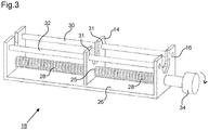
- Figure 3 depicts an alternative configuration for the displacement device 18.
- the displacement device 18 comprises a threaded bar 28 mounted rotatably in a frame 26 that is an integral part of or is rigidly attached to a handle 26.
- One of the first and second anchor members 14 and 16 comprises a threaded orifice 25 (the first engagement member 14 in this example).
- the threaded bar 28 extends through the orifice 25 and an outer thread of the threaded bar 28 engages with an inner thread of the threaded orifice 25.
- the anchor member 14 having the threaded orifice 25 is mounted so as to be movable parallel to an axis of rotation of the threaded bar 28 but is constrained so as not to be rotatable about the axis of rotation of the threaded bar 28.
- a gripping device 34 may be provided to allow a user to impart rotation to the threaded bar 28.
- the pitch of the threads on the threaded bar 28 and/or the radial size of the gripping device 34 may be varied according to the desired sensitivity that is required for the operator. For example, when high precision is required, a relatively fine thread and/or a radially large gripping device 34 may be provided. Conversely, when it is desired to impart quicker motion to the first and second engagement members, a coarser thread and/or smaller gripping device 34 may be provided.
- a kit for use in conjunction with a catheter assembly 1, for example of the type illustrated in Figure 1 .
- the kit may comprise first and second anchor members which are couplable to proximal ends of the holding catheter and stopper member.
- the holding catheter and stopper members may not themselves comprise anchor members.
- the catheter assembly 1 may comprise elements which act as anchor members but the kit may provide additional anchor members which improve the connection between the catheter assembly 1 and the displacement device 18.
- the additional anchor members may comprise washers or similar, for example, which may be mounted onto appropriate parts of the catheter assembly.
- the kit further comprises the displacement device itself.
Landscapes
- Health & Medical Sciences (AREA)
- Engineering & Computer Science (AREA)
- Biomedical Technology (AREA)
- Cardiology (AREA)
- Oral & Maxillofacial Surgery (AREA)
- Transplantation (AREA)
- Heart & Thoracic Surgery (AREA)
- Vascular Medicine (AREA)
- Life Sciences & Earth Sciences (AREA)
- Animal Behavior & Ethology (AREA)
- General Health & Medical Sciences (AREA)
- Public Health (AREA)
- Veterinary Medicine (AREA)
- Media Introduction/Drainage Providing Device (AREA)
- Prostheses (AREA)
Priority Applications (1)
| Application Number | Priority Date | Filing Date | Title |
|---|---|---|---|
| PL15705080T PL3107505T3 (pl) | 2014-02-17 | 2015-02-16 | Urządzenie do umieszczania stentu |
Applications Claiming Priority (2)
| Application Number | Priority Date | Filing Date | Title |
|---|---|---|---|
| GB201402758A GB201402758D0 (en) | 2014-02-17 | 2014-02-17 | Stent placement device |
| PCT/GB2015/050427 WO2015121678A1 (en) | 2014-02-17 | 2015-02-16 | Stent placement device |
Publications (2)
| Publication Number | Publication Date |
|---|---|
| EP3107505A1 EP3107505A1 (en) | 2016-12-28 |
| EP3107505B1 true EP3107505B1 (en) | 2017-11-15 |
Family
ID=50440278
Family Applications (1)
| Application Number | Title | Priority Date | Filing Date |
|---|---|---|---|
| EP15705080.8A Active EP3107505B1 (en) | 2014-02-17 | 2015-02-16 | Stent placement device |
Country Status (11)
| Country | Link |
|---|---|
| US (1) | US10548751B2 (enExample) |
| EP (1) | EP3107505B1 (enExample) |
| JP (1) | JP2017508575A (enExample) |
| CN (1) | CN106255478B (enExample) |
| DK (1) | DK3107505T3 (enExample) |
| ES (1) | ES2655928T3 (enExample) |
| GB (1) | GB201402758D0 (enExample) |
| HU (1) | HUE036526T2 (enExample) |
| NO (1) | NO3107505T3 (enExample) |
| PL (1) | PL3107505T3 (enExample) |
| WO (1) | WO2015121678A1 (enExample) |
Families Citing this family (2)
| Publication number | Priority date | Publication date | Assignee | Title |
|---|---|---|---|---|
| US11992241B2 (en) * | 2020-01-31 | 2024-05-28 | DePuy Synthes Products, Inc. | System to assist delivery of a mechanical intravascular treatment device |
| CN118664864B (zh) * | 2024-08-20 | 2024-12-20 | 潍坊市英创上润包装制品有限公司 | 一种塑料管制备系统及其应用方法 |
Family Cites Families (18)
| Publication number | Priority date | Publication date | Assignee | Title |
|---|---|---|---|---|
| US6786918B1 (en) | 2000-10-17 | 2004-09-07 | Medtronic Vascular, Inc. | Stent delivery system |
| ES2373782T3 (es) | 2001-02-08 | 2012-02-08 | Tyco Healthcare Group Lp | Instrumento quirúrgico ultrasónico. |
| US6926732B2 (en) * | 2001-06-01 | 2005-08-09 | Ams Research Corporation | Stent delivery device and method |
| US7358383B2 (en) | 2003-01-24 | 2008-04-15 | University Of South Florida | Polyphenol proteasome inhibitors, synthesis, and methods of use |
| IL170698A (en) | 2005-09-06 | 2011-11-30 | Allium Ltd | System for delivering a medical device to a body location |
| US8167892B2 (en) | 2005-12-29 | 2012-05-01 | Cordis Corporation | Adjustable and detached stent deployment device |
| DE102006004123A1 (de) | 2006-01-25 | 2007-08-02 | Jotec Gmbh | Einführsystem für Stents mit Zug-Druck-Kinematik |
| US8518098B2 (en) | 2006-02-21 | 2013-08-27 | Cook Medical Technologies Llc | Split sheath deployment system |
| WO2007122901A1 (ja) * | 2006-03-31 | 2007-11-01 | Zeon Corporation | ステントデリバリーカテーテル |
| US8808345B2 (en) | 2008-12-31 | 2014-08-19 | Medtronic Ardian Luxembourg S.A.R.L. | Handle assemblies for intravascular treatment devices and associated systems and methods |
| US20120238806A1 (en) * | 2009-08-24 | 2012-09-20 | Quali-Med Gmbh | Implantation system with handle and catheter and method of use thereof |
| US9301864B2 (en) | 2010-06-08 | 2016-04-05 | Veniti, Inc. | Bi-directional stent delivery system |
| CA2806234C (en) * | 2010-07-30 | 2015-03-24 | Cook Medical Technologies Llc | Controlled release and recapture prosthetic deployment device |
| EP2428189A1 (en) | 2010-09-10 | 2012-03-14 | Symetis Sa | Catheter delivery system for stent valve |
| US20120185031A1 (en) * | 2011-01-19 | 2012-07-19 | Michael Ryan | Rotary and linear handle mechanism for constrained stent delivery system |
| EP2604231B1 (de) * | 2011-12-12 | 2016-04-06 | Biotronik AG | Freigabevorrichtung zum Lösen eines medizinischen Implantats von einem Katheter sowie Katheter mit einer Freigabevorrichtung |
| US9439796B2 (en) * | 2013-03-15 | 2016-09-13 | Cook Medical Technologies Llc | Prosthesis delivery device |
| CN103356316B (zh) * | 2013-07-25 | 2015-07-01 | 苏州英络医疗器械有限公司 | 高回缩性血管支架输送系统 |
-
2014
- 2014-02-17 GB GB201402758A patent/GB201402758D0/en not_active Ceased
-
2015
- 2015-02-16 PL PL15705080T patent/PL3107505T3/pl unknown
- 2015-02-16 WO PCT/GB2015/050427 patent/WO2015121678A1/en not_active Ceased
- 2015-02-16 JP JP2016569107A patent/JP2017508575A/ja active Pending
- 2015-02-16 NO NO15705080A patent/NO3107505T3/no unknown
- 2015-02-16 US US15/119,303 patent/US10548751B2/en active Active
- 2015-02-16 ES ES15705080.8T patent/ES2655928T3/es active Active
- 2015-02-16 EP EP15705080.8A patent/EP3107505B1/en active Active
- 2015-02-16 HU HUE15705080A patent/HUE036526T2/hu unknown
- 2015-02-16 CN CN201580008937.6A patent/CN106255478B/zh active Active
- 2015-02-16 DK DK15705080.8T patent/DK3107505T3/en active
Non-Patent Citations (1)
| Title |
|---|
| None * |
Also Published As
| Publication number | Publication date |
|---|---|
| NO3107505T3 (enExample) | 2018-04-14 |
| CN106255478A (zh) | 2016-12-21 |
| US20170007433A1 (en) | 2017-01-12 |
| US10548751B2 (en) | 2020-02-04 |
| JP2017508575A (ja) | 2017-03-30 |
| PL3107505T3 (pl) | 2018-04-30 |
| ES2655928T3 (es) | 2018-02-22 |
| GB201402758D0 (en) | 2014-04-02 |
| DK3107505T3 (en) | 2018-01-08 |
| HUE036526T2 (hu) | 2018-07-30 |
| WO2015121678A1 (en) | 2015-08-20 |
| EP3107505A1 (en) | 2016-12-28 |
| CN106255478B (zh) | 2017-10-27 |
Similar Documents
| Publication | Publication Date | Title |
|---|---|---|
| JP6625124B2 (ja) | 人工器官のための反転送達デバイスおよび方法 | |
| EP2341871B1 (en) | Delivery system for vascular implant | |
| EP1380271B1 (en) | Locking handle deployment mechanism for medical device | |
| EP2419041B1 (en) | Implant delivery system | |
| EP2522316B1 (en) | Introducer with ratchet handle drive | |
| EP2611396B1 (en) | Single handed deployment handle | |
| EP3031410B1 (en) | Medical implant detachment mechanism and introducer assembly | |
| JP6211064B2 (ja) | 経カテーテル心臓弁送達のための装置および方法 | |
| US20090030495A1 (en) | System for controlled prosthesis deployment | |
| TW201632154A (zh) | 具有近側限位器和在近側限位器遠側的環狀鎖的可再約束支架輸送系統及方法 | |
| JP2010536418A (ja) | 配置装置 | |
| JP2007195963A (ja) | 調整可能で分離したステント配備装置 | |
| WO2018102525A1 (en) | Transcatheter delivery system with two modes of actuation | |
| EP3107505B1 (en) | Stent placement device | |
| CN107233145B (zh) | 用于假体的倒转传输设备和方法 | |
| EP3700476B1 (en) | Stent delivery catheter system with slow speed control via pin and slot with fast speed control tab |
Legal Events
| Date | Code | Title | Description |
|---|---|---|---|
| PUAI | Public reference made under article 153(3) epc to a published international application that has entered the european phase |
Free format text: ORIGINAL CODE: 0009012 |
|
| STAA | Information on the status of an ep patent application or granted ep patent |
Free format text: STATUS: REQUEST FOR EXAMINATION WAS MADE |
|
| 17P | Request for examination filed |
Effective date: 20160823 |
|
| AK | Designated contracting states |
Kind code of ref document: A1 Designated state(s): AL AT BE BG CH CY CZ DE DK EE ES FI FR GB GR HR HU IE IS IT LI LT LU LV MC MK MT NL NO PL PT RO RS SE SI SK SM TR |
|
| AX | Request for extension of the european patent |
Extension state: BA ME |
|
| RAP1 | Party data changed (applicant data changed or rights of an application transferred) |
Owner name: OXFORD UNIVERSITY INNOVATION LIMITED |
|
| DAX | Request for extension of the european patent (deleted) | ||
| GRAP | Despatch of communication of intention to grant a patent |
Free format text: ORIGINAL CODE: EPIDOSNIGR1 |
|
| STAA | Information on the status of an ep patent application or granted ep patent |
Free format text: STATUS: GRANT OF PATENT IS INTENDED |
|
| INTG | Intention to grant announced |
Effective date: 20170630 |
|
| GRAS | Grant fee paid |
Free format text: ORIGINAL CODE: EPIDOSNIGR3 |
|
| GRAA | (expected) grant |
Free format text: ORIGINAL CODE: 0009210 |
|
| STAA | Information on the status of an ep patent application or granted ep patent |
Free format text: STATUS: THE PATENT HAS BEEN GRANTED |
|
| AK | Designated contracting states |
Kind code of ref document: B1 Designated state(s): AL AT BE BG CH CY CZ DE DK EE ES FI FR GB GR HR HU IE IS IT LI LT LU LV MC MK MT NL NO PL PT RO RS SE SI SK SM TR |
|
| REG | Reference to a national code |
Ref country code: AT Ref legal event code: REF Ref document number: 945538 Country of ref document: AT Kind code of ref document: T Effective date: 20171115 Ref country code: GB Ref legal event code: FG4D Ref country code: CH Ref legal event code: EP |
|
| REG | Reference to a national code |
Ref country code: IE Ref legal event code: FG4D |
|
| REG | Reference to a national code |
Ref country code: DE Ref legal event code: R096 Ref document number: 602015006039 Country of ref document: DE |
|
| REG | Reference to a national code |
Ref country code: SE Ref legal event code: TRGR |
|
| REG | Reference to a national code |
Ref country code: DK Ref legal event code: T3 Effective date: 20180104 |
|
| REG | Reference to a national code |
Ref country code: CH Ref legal event code: NV Representative=s name: VENI GMBH, CH |
|
| REG | Reference to a national code |
Ref country code: NL Ref legal event code: FP |
|
| REG | Reference to a national code |
Ref country code: ES Ref legal event code: FG2A Ref document number: 2655928 Country of ref document: ES Kind code of ref document: T3 Effective date: 20180222 |
|
| REG | Reference to a national code |
Ref country code: FR Ref legal event code: PLFP Year of fee payment: 4 |
|
| REG | Reference to a national code |
Ref country code: LT Ref legal event code: MG4D |
|
| REG | Reference to a national code |
Ref country code: NO Ref legal event code: T2 Effective date: 20171115 |
|
| PG25 | Lapsed in a contracting state [announced via postgrant information from national office to epo] |
Ref country code: LT Free format text: LAPSE BECAUSE OF FAILURE TO SUBMIT A TRANSLATION OF THE DESCRIPTION OR TO PAY THE FEE WITHIN THE PRESCRIBED TIME-LIMIT Effective date: 20171115 |
|
| PG25 | Lapsed in a contracting state [announced via postgrant information from national office to epo] |
Ref country code: RS Free format text: LAPSE BECAUSE OF FAILURE TO SUBMIT A TRANSLATION OF THE DESCRIPTION OR TO PAY THE FEE WITHIN THE PRESCRIBED TIME-LIMIT Effective date: 20171115 Ref country code: LV Free format text: LAPSE BECAUSE OF FAILURE TO SUBMIT A TRANSLATION OF THE DESCRIPTION OR TO PAY THE FEE WITHIN THE PRESCRIBED TIME-LIMIT Effective date: 20171115 Ref country code: BG Free format text: LAPSE BECAUSE OF FAILURE TO SUBMIT A TRANSLATION OF THE DESCRIPTION OR TO PAY THE FEE WITHIN THE PRESCRIBED TIME-LIMIT Effective date: 20180215 Ref country code: HR Free format text: LAPSE BECAUSE OF FAILURE TO SUBMIT A TRANSLATION OF THE DESCRIPTION OR TO PAY THE FEE WITHIN THE PRESCRIBED TIME-LIMIT Effective date: 20171115 |
|
| REG | Reference to a national code |
Ref country code: GR Ref legal event code: EP Ref document number: 20180400343 Country of ref document: GR Effective date: 20180627 |
|
| REG | Reference to a national code |
Ref country code: HU Ref legal event code: AG4A Ref document number: E036526 Country of ref document: HU |
|
| PG25 | Lapsed in a contracting state [announced via postgrant information from national office to epo] |
Ref country code: CY Free format text: LAPSE BECAUSE OF FAILURE TO SUBMIT A TRANSLATION OF THE DESCRIPTION OR TO PAY THE FEE WITHIN THE PRESCRIBED TIME-LIMIT Effective date: 20171115 Ref country code: EE Free format text: LAPSE BECAUSE OF FAILURE TO SUBMIT A TRANSLATION OF THE DESCRIPTION OR TO PAY THE FEE WITHIN THE PRESCRIBED TIME-LIMIT Effective date: 20171115 Ref country code: SK Free format text: LAPSE BECAUSE OF FAILURE TO SUBMIT A TRANSLATION OF THE DESCRIPTION OR TO PAY THE FEE WITHIN THE PRESCRIBED TIME-LIMIT Effective date: 20171115 |
|
| REG | Reference to a national code |
Ref country code: DE Ref legal event code: R097 Ref document number: 602015006039 Country of ref document: DE |
|
| PG25 | Lapsed in a contracting state [announced via postgrant information from national office to epo] |
Ref country code: SM Free format text: LAPSE BECAUSE OF FAILURE TO SUBMIT A TRANSLATION OF THE DESCRIPTION OR TO PAY THE FEE WITHIN THE PRESCRIBED TIME-LIMIT Effective date: 20171115 |
|
| PLBE | No opposition filed within time limit |
Free format text: ORIGINAL CODE: 0009261 |
|
| STAA | Information on the status of an ep patent application or granted ep patent |
Free format text: STATUS: NO OPPOSITION FILED WITHIN TIME LIMIT |
|
| PG25 | Lapsed in a contracting state [announced via postgrant information from national office to epo] |
Ref country code: MC Free format text: LAPSE BECAUSE OF FAILURE TO SUBMIT A TRANSLATION OF THE DESCRIPTION OR TO PAY THE FEE WITHIN THE PRESCRIBED TIME-LIMIT Effective date: 20171115 |
|
| 26N | No opposition filed |
Effective date: 20180817 |
|
| PG25 | Lapsed in a contracting state [announced via postgrant information from national office to epo] |
Ref country code: SI Free format text: LAPSE BECAUSE OF FAILURE TO SUBMIT A TRANSLATION OF THE DESCRIPTION OR TO PAY THE FEE WITHIN THE PRESCRIBED TIME-LIMIT Effective date: 20171115 Ref country code: LU Free format text: LAPSE BECAUSE OF NON-PAYMENT OF DUE FEES Effective date: 20180216 |
|
| PG25 | Lapsed in a contracting state [announced via postgrant information from national office to epo] |
Ref country code: MT Free format text: LAPSE BECAUSE OF NON-PAYMENT OF DUE FEES Effective date: 20180216 |
|
| PG25 | Lapsed in a contracting state [announced via postgrant information from national office to epo] |
Ref country code: PT Free format text: LAPSE BECAUSE OF FAILURE TO SUBMIT A TRANSLATION OF THE DESCRIPTION OR TO PAY THE FEE WITHIN THE PRESCRIBED TIME-LIMIT Effective date: 20171115 |
|
| PG25 | Lapsed in a contracting state [announced via postgrant information from national office to epo] |
Ref country code: MK Free format text: LAPSE BECAUSE OF NON-PAYMENT OF DUE FEES Effective date: 20171115 Ref country code: RO Free format text: LAPSE BECAUSE OF FAILURE TO SUBMIT A TRANSLATION OF THE DESCRIPTION OR TO PAY THE FEE WITHIN THE PRESCRIBED TIME-LIMIT Effective date: 20171115 |
|
| PG25 | Lapsed in a contracting state [announced via postgrant information from national office to epo] |
Ref country code: IS Free format text: LAPSE BECAUSE OF FAILURE TO SUBMIT A TRANSLATION OF THE DESCRIPTION OR TO PAY THE FEE WITHIN THE PRESCRIBED TIME-LIMIT Effective date: 20180315 Ref country code: AL Free format text: LAPSE BECAUSE OF FAILURE TO SUBMIT A TRANSLATION OF THE DESCRIPTION OR TO PAY THE FEE WITHIN THE PRESCRIBED TIME-LIMIT Effective date: 20171115 |
|
| REG | Reference to a national code |
Ref country code: AT Ref legal event code: UEP Ref document number: 945538 Country of ref document: AT Kind code of ref document: T Effective date: 20171115 |
|
| PGFP | Annual fee paid to national office [announced via postgrant information from national office to epo] |
Ref country code: IE Payment date: 20220119 Year of fee payment: 8 Ref country code: HU Payment date: 20220214 Year of fee payment: 8 Ref country code: FI Payment date: 20220215 Year of fee payment: 8 Ref country code: DK Payment date: 20220221 Year of fee payment: 8 Ref country code: CH Payment date: 20220221 Year of fee payment: 8 Ref country code: AT Payment date: 20220215 Year of fee payment: 8 |
|
| PGFP | Annual fee paid to national office [announced via postgrant information from national office to epo] |
Ref country code: TR Payment date: 20220203 Year of fee payment: 8 Ref country code: SE Payment date: 20220121 Year of fee payment: 8 Ref country code: PL Payment date: 20220210 Year of fee payment: 8 Ref country code: NO Payment date: 20220204 Year of fee payment: 8 Ref country code: NL Payment date: 20220216 Year of fee payment: 8 Ref country code: GR Payment date: 20220216 Year of fee payment: 8 Ref country code: CZ Payment date: 20220204 Year of fee payment: 8 Ref country code: BE Payment date: 20220216 Year of fee payment: 8 |
|
| REG | Reference to a national code |
Ref country code: NO Ref legal event code: MMEP Ref country code: DK Ref legal event code: EBP Effective date: 20230228 |
|
| REG | Reference to a national code |
Ref country code: CH Ref legal event code: PL |
|
| REG | Reference to a national code |
Ref country code: SE Ref legal event code: EUG |
|
| REG | Reference to a national code |
Ref country code: NL Ref legal event code: MM Effective date: 20230301 |
|
| REG | Reference to a national code |
Ref country code: AT Ref legal event code: MM01 Ref document number: 945538 Country of ref document: AT Kind code of ref document: T Effective date: 20230216 |
|
| REG | Reference to a national code |
Ref country code: BE Ref legal event code: MM Effective date: 20230228 |
|
| PG25 | Lapsed in a contracting state [announced via postgrant information from national office to epo] |
Ref country code: SE Free format text: LAPSE BECAUSE OF NON-PAYMENT OF DUE FEES Effective date: 20230217 Ref country code: NO Free format text: LAPSE BECAUSE OF NON-PAYMENT OF DUE FEES Effective date: 20230228 Ref country code: LI Free format text: LAPSE BECAUSE OF NON-PAYMENT OF DUE FEES Effective date: 20230228 Ref country code: FI Free format text: LAPSE BECAUSE OF NON-PAYMENT OF DUE FEES Effective date: 20230216 Ref country code: CZ Free format text: LAPSE BECAUSE OF NON-PAYMENT OF DUE FEES Effective date: 20230216 Ref country code: CH Free format text: LAPSE BECAUSE OF NON-PAYMENT OF DUE FEES Effective date: 20230228 Ref country code: AT Free format text: LAPSE BECAUSE OF NON-PAYMENT OF DUE FEES Effective date: 20230216 |
|
| PG25 | Lapsed in a contracting state [announced via postgrant information from national office to epo] |
Ref country code: NL Free format text: LAPSE BECAUSE OF NON-PAYMENT OF DUE FEES Effective date: 20230301 Ref country code: HU Free format text: LAPSE BECAUSE OF NON-PAYMENT OF DUE FEES Effective date: 20230217 Ref country code: GR Free format text: LAPSE BECAUSE OF NON-PAYMENT OF DUE FEES Effective date: 20230906 |
|
| REG | Reference to a national code |
Ref country code: IE Ref legal event code: MM4A |
|
| PG25 | Lapsed in a contracting state [announced via postgrant information from national office to epo] |
Ref country code: IE Free format text: LAPSE BECAUSE OF NON-PAYMENT OF DUE FEES Effective date: 20230216 Ref country code: DK Free format text: LAPSE BECAUSE OF NON-PAYMENT OF DUE FEES Effective date: 20230228 |
|
| PG25 | Lapsed in a contracting state [announced via postgrant information from national office to epo] |
Ref country code: BE Free format text: LAPSE BECAUSE OF NON-PAYMENT OF DUE FEES Effective date: 20230228 |
|
| PG25 | Lapsed in a contracting state [announced via postgrant information from national office to epo] |
Ref country code: PL Free format text: LAPSE BECAUSE OF NON-PAYMENT OF DUE FEES Effective date: 20230216 |
|
| PG25 | Lapsed in a contracting state [announced via postgrant information from national office to epo] |
Ref country code: PL Free format text: LAPSE BECAUSE OF NON-PAYMENT OF DUE FEES Effective date: 20230216 |
|
| PGFP | Annual fee paid to national office [announced via postgrant information from national office to epo] |
Ref country code: DE Payment date: 20250326 Year of fee payment: 11 |
|
| PGFP | Annual fee paid to national office [announced via postgrant information from national office to epo] |
Ref country code: ES Payment date: 20250328 Year of fee payment: 11 |
|
| PGFP | Annual fee paid to national office [announced via postgrant information from national office to epo] |
Ref country code: FR Payment date: 20250320 Year of fee payment: 11 |
|
| PGFP | Annual fee paid to national office [announced via postgrant information from national office to epo] |
Ref country code: GB Payment date: 20250320 Year of fee payment: 11 |
|
| PGFP | Annual fee paid to national office [announced via postgrant information from national office to epo] |
Ref country code: IT Payment date: 20250327 Year of fee payment: 11 |