EP3700476B1 - Stent delivery catheter system with slow speed control via pin and slot with fast speed control tab - Google Patents
Stent delivery catheter system with slow speed control via pin and slot with fast speed control tab Download PDFInfo
- Publication number
- EP3700476B1 EP3700476B1 EP18833109.4A EP18833109A EP3700476B1 EP 3700476 B1 EP3700476 B1 EP 3700476B1 EP 18833109 A EP18833109 A EP 18833109A EP 3700476 B1 EP3700476 B1 EP 3700476B1
- Authority
- EP
- European Patent Office
- Prior art keywords
- button
- shuttle
- housing
- rack
- longitudinal axis
- Prior art date
- Legal status (The legal status is an assumption and is not a legal conclusion. Google has not performed a legal analysis and makes no representation as to the accuracy of the status listed.)
- Active
Links
- 238000006073 displacement reaction Methods 0.000 claims description 2
- 230000008859 change Effects 0.000 description 10
- 239000000463 material Substances 0.000 description 9
- 238000000034 method Methods 0.000 description 6
- 208000031481 Pathologic Constriction Diseases 0.000 description 3
- 239000010935 stainless steel Substances 0.000 description 3
- 229910001220 stainless steel Inorganic materials 0.000 description 3
- 230000036262 stenosis Effects 0.000 description 3
- 208000037804 stenosis Diseases 0.000 description 3
- 210000003484 anatomy Anatomy 0.000 description 2
- 239000000560 biocompatible material Substances 0.000 description 2
- 230000000994 depressogenic effect Effects 0.000 description 2
- 230000003902 lesion Effects 0.000 description 2
- 230000007246 mechanism Effects 0.000 description 2
- 229910052751 metal Inorganic materials 0.000 description 2
- 239000002184 metal Substances 0.000 description 2
- HLXZNVUGXRDIFK-UHFFFAOYSA-N nickel titanium Chemical compound [Ti].[Ti].[Ti].[Ti].[Ti].[Ti].[Ti].[Ti].[Ti].[Ti].[Ti].[Ni].[Ni].[Ni].[Ni].[Ni].[Ni].[Ni].[Ni].[Ni].[Ni].[Ni].[Ni].[Ni].[Ni] HLXZNVUGXRDIFK-UHFFFAOYSA-N 0.000 description 2
- 229910001000 nickel titanium Inorganic materials 0.000 description 2
- BASFCYQUMIYNBI-UHFFFAOYSA-N platinum Chemical compound [Pt] BASFCYQUMIYNBI-UHFFFAOYSA-N 0.000 description 2
- 239000013047 polymeric layer Substances 0.000 description 2
- 229910000684 Cobalt-chrome Inorganic materials 0.000 description 1
- 241001465754 Metazoa Species 0.000 description 1
- 239000004952 Polyamide Substances 0.000 description 1
- 239000004698 Polyethylene Substances 0.000 description 1
- 239000004642 Polyimide Substances 0.000 description 1
- WAIPAZQMEIHHTJ-UHFFFAOYSA-N [Cr].[Co] Chemical compound [Cr].[Co] WAIPAZQMEIHHTJ-UHFFFAOYSA-N 0.000 description 1
- 230000006978 adaptation Effects 0.000 description 1
- 230000017531 blood circulation Effects 0.000 description 1
- 239000010952 cobalt-chrome Substances 0.000 description 1
- 230000008878 coupling Effects 0.000 description 1
- 238000010168 coupling process Methods 0.000 description 1
- 238000005859 coupling reaction Methods 0.000 description 1
- 201000010099 disease Diseases 0.000 description 1
- 208000037265 diseases, disorders, signs and symptoms Diseases 0.000 description 1
- 210000003811 finger Anatomy 0.000 description 1
- 238000002594 fluoroscopy Methods 0.000 description 1
- 230000006870 function Effects 0.000 description 1
- 230000036541 health Effects 0.000 description 1
- 238000003780 insertion Methods 0.000 description 1
- 230000037431 insertion Effects 0.000 description 1
- 239000010410 layer Substances 0.000 description 1
- 229920001778 nylon Polymers 0.000 description 1
- 238000004806 packaging method and process Methods 0.000 description 1
- 229910052697 platinum Inorganic materials 0.000 description 1
- 229920002647 polyamide Polymers 0.000 description 1
- 229920000515 polycarbonate Polymers 0.000 description 1
- 239000004417 polycarbonate Substances 0.000 description 1
- 229920000728 polyester Polymers 0.000 description 1
- 229920000570 polyether Polymers 0.000 description 1
- 229920000573 polyethylene Polymers 0.000 description 1
- -1 polyethylenes Polymers 0.000 description 1
- 229920001721 polyimide Polymers 0.000 description 1
- 229920000642 polymer Polymers 0.000 description 1
- 229920002635 polyurethane Polymers 0.000 description 1
- 239000004814 polyurethane Substances 0.000 description 1
- 230000003014 reinforcing effect Effects 0.000 description 1
- 230000000717 retained effect Effects 0.000 description 1
- 230000001954 sterilising effect Effects 0.000 description 1
- 238000004659 sterilization and disinfection Methods 0.000 description 1
- 210000003813 thumb Anatomy 0.000 description 1
- WFKWXMTUELFFGS-UHFFFAOYSA-N tungsten Chemical compound [W] WFKWXMTUELFFGS-UHFFFAOYSA-N 0.000 description 1
- 229910052721 tungsten Inorganic materials 0.000 description 1
- 239000010937 tungsten Substances 0.000 description 1
- 230000002792 vascular Effects 0.000 description 1
Images


Classifications
-
- A—HUMAN NECESSITIES
- A61—MEDICAL OR VETERINARY SCIENCE; HYGIENE
- A61F—FILTERS IMPLANTABLE INTO BLOOD VESSELS; PROSTHESES; DEVICES PROVIDING PATENCY TO, OR PREVENTING COLLAPSING OF, TUBULAR STRUCTURES OF THE BODY, e.g. STENTS; ORTHOPAEDIC, NURSING OR CONTRACEPTIVE DEVICES; FOMENTATION; TREATMENT OR PROTECTION OF EYES OR EARS; BANDAGES, DRESSINGS OR ABSORBENT PADS; FIRST-AID KITS
- A61F2/00—Filters implantable into blood vessels; Prostheses, i.e. artificial substitutes or replacements for parts of the body; Appliances for connecting them with the body; Devices providing patency to, or preventing collapsing of, tubular structures of the body, e.g. stents
- A61F2/95—Instruments specially adapted for placement or removal of stents or stent-grafts
- A61F2/962—Instruments specially adapted for placement or removal of stents or stent-grafts having an outer sleeve
- A61F2/97—Instruments specially adapted for placement or removal of stents or stent-grafts having an outer sleeve the outer sleeve being splittable
-
- A—HUMAN NECESSITIES
- A61—MEDICAL OR VETERINARY SCIENCE; HYGIENE
- A61F—FILTERS IMPLANTABLE INTO BLOOD VESSELS; PROSTHESES; DEVICES PROVIDING PATENCY TO, OR PREVENTING COLLAPSING OF, TUBULAR STRUCTURES OF THE BODY, e.g. STENTS; ORTHOPAEDIC, NURSING OR CONTRACEPTIVE DEVICES; FOMENTATION; TREATMENT OR PROTECTION OF EYES OR EARS; BANDAGES, DRESSINGS OR ABSORBENT PADS; FIRST-AID KITS
- A61F2/00—Filters implantable into blood vessels; Prostheses, i.e. artificial substitutes or replacements for parts of the body; Appliances for connecting them with the body; Devices providing patency to, or preventing collapsing of, tubular structures of the body, e.g. stents
- A61F2/95—Instruments specially adapted for placement or removal of stents or stent-grafts
- A61F2/962—Instruments specially adapted for placement or removal of stents or stent-grafts having an outer sleeve
- A61F2/966—Instruments specially adapted for placement or removal of stents or stent-grafts having an outer sleeve with relative longitudinal movement between outer sleeve and prosthesis, e.g. using a push rod
-
- A—HUMAN NECESSITIES
- A61—MEDICAL OR VETERINARY SCIENCE; HYGIENE
- A61F—FILTERS IMPLANTABLE INTO BLOOD VESSELS; PROSTHESES; DEVICES PROVIDING PATENCY TO, OR PREVENTING COLLAPSING OF, TUBULAR STRUCTURES OF THE BODY, e.g. STENTS; ORTHOPAEDIC, NURSING OR CONTRACEPTIVE DEVICES; FOMENTATION; TREATMENT OR PROTECTION OF EYES OR EARS; BANDAGES, DRESSINGS OR ABSORBENT PADS; FIRST-AID KITS
- A61F2/00—Filters implantable into blood vessels; Prostheses, i.e. artificial substitutes or replacements for parts of the body; Appliances for connecting them with the body; Devices providing patency to, or preventing collapsing of, tubular structures of the body, e.g. stents
- A61F2/82—Devices providing patency to, or preventing collapsing of, tubular structures of the body, e.g. stents
- A61F2/844—Devices providing patency to, or preventing collapsing of, tubular structures of the body, e.g. stents folded prior to deployment
-
- A—HUMAN NECESSITIES
- A61—MEDICAL OR VETERINARY SCIENCE; HYGIENE
- A61F—FILTERS IMPLANTABLE INTO BLOOD VESSELS; PROSTHESES; DEVICES PROVIDING PATENCY TO, OR PREVENTING COLLAPSING OF, TUBULAR STRUCTURES OF THE BODY, e.g. STENTS; ORTHOPAEDIC, NURSING OR CONTRACEPTIVE DEVICES; FOMENTATION; TREATMENT OR PROTECTION OF EYES OR EARS; BANDAGES, DRESSINGS OR ABSORBENT PADS; FIRST-AID KITS
- A61F2/00—Filters implantable into blood vessels; Prostheses, i.e. artificial substitutes or replacements for parts of the body; Appliances for connecting them with the body; Devices providing patency to, or preventing collapsing of, tubular structures of the body, e.g. stents
- A61F2/95—Instruments specially adapted for placement or removal of stents or stent-grafts
- A61F2/9517—Instruments specially adapted for placement or removal of stents or stent-grafts handle assemblies therefor
-
- A—HUMAN NECESSITIES
- A61—MEDICAL OR VETERINARY SCIENCE; HYGIENE
- A61M—DEVICES FOR INTRODUCING MEDIA INTO, OR ONTO, THE BODY; DEVICES FOR TRANSDUCING BODY MEDIA OR FOR TAKING MEDIA FROM THE BODY; DEVICES FOR PRODUCING OR ENDING SLEEP OR STUPOR
- A61M25/00—Catheters; Hollow probes
- A61M25/01—Introducing, guiding, advancing, emplacing or holding catheters
- A61M25/06—Body-piercing guide needles or the like
- A61M25/0662—Guide tubes
-
- A—HUMAN NECESSITIES
- A61—MEDICAL OR VETERINARY SCIENCE; HYGIENE
- A61B—DIAGNOSIS; SURGERY; IDENTIFICATION
- A61B17/00—Surgical instruments, devices or methods, e.g. tourniquets
- A61B2017/00367—Details of actuation of instruments, e.g. relations between pushing buttons, or the like, and activation of the tool, working tip, or the like
- A61B2017/00407—Ratchet means
-
- A—HUMAN NECESSITIES
- A61—MEDICAL OR VETERINARY SCIENCE; HYGIENE
- A61B—DIAGNOSIS; SURGERY; IDENTIFICATION
- A61B17/00—Surgical instruments, devices or methods, e.g. tourniquets
- A61B2017/0042—Surgical instruments, devices or methods, e.g. tourniquets with special provisions for gripping
-
- A—HUMAN NECESSITIES
- A61—MEDICAL OR VETERINARY SCIENCE; HYGIENE
- A61F—FILTERS IMPLANTABLE INTO BLOOD VESSELS; PROSTHESES; DEVICES PROVIDING PATENCY TO, OR PREVENTING COLLAPSING OF, TUBULAR STRUCTURES OF THE BODY, e.g. STENTS; ORTHOPAEDIC, NURSING OR CONTRACEPTIVE DEVICES; FOMENTATION; TREATMENT OR PROTECTION OF EYES OR EARS; BANDAGES, DRESSINGS OR ABSORBENT PADS; FIRST-AID KITS
- A61F2/00—Filters implantable into blood vessels; Prostheses, i.e. artificial substitutes or replacements for parts of the body; Appliances for connecting them with the body; Devices providing patency to, or preventing collapsing of, tubular structures of the body, e.g. stents
- A61F2/95—Instruments specially adapted for placement or removal of stents or stent-grafts
- A61F2/962—Instruments specially adapted for placement or removal of stents or stent-grafts having an outer sleeve
- A61F2/966—Instruments specially adapted for placement or removal of stents or stent-grafts having an outer sleeve with relative longitudinal movement between outer sleeve and prosthesis, e.g. using a push rod
- A61F2002/9665—Instruments specially adapted for placement or removal of stents or stent-grafts having an outer sleeve with relative longitudinal movement between outer sleeve and prosthesis, e.g. using a push rod with additional retaining means
-
- A—HUMAN NECESSITIES
- A61—MEDICAL OR VETERINARY SCIENCE; HYGIENE
- A61F—FILTERS IMPLANTABLE INTO BLOOD VESSELS; PROSTHESES; DEVICES PROVIDING PATENCY TO, OR PREVENTING COLLAPSING OF, TUBULAR STRUCTURES OF THE BODY, e.g. STENTS; ORTHOPAEDIC, NURSING OR CONTRACEPTIVE DEVICES; FOMENTATION; TREATMENT OR PROTECTION OF EYES OR EARS; BANDAGES, DRESSINGS OR ABSORBENT PADS; FIRST-AID KITS
- A61F2210/00—Particular material properties of prostheses classified in groups A61F2/00 - A61F2/26 or A61F2/82 or A61F9/00 or A61F11/00 or subgroups thereof
- A61F2210/0061—Particular material properties of prostheses classified in groups A61F2/00 - A61F2/26 or A61F2/82 or A61F9/00 or A61F11/00 or subgroups thereof swellable
-
- A—HUMAN NECESSITIES
- A61—MEDICAL OR VETERINARY SCIENCE; HYGIENE
- A61M—DEVICES FOR INTRODUCING MEDIA INTO, OR ONTO, THE BODY; DEVICES FOR TRANSDUCING BODY MEDIA OR FOR TAKING MEDIA FROM THE BODY; DEVICES FOR PRODUCING OR ENDING SLEEP OR STUPOR
- A61M25/00—Catheters; Hollow probes
- A61M25/01—Introducing, guiding, advancing, emplacing or holding catheters
- A61M25/06—Body-piercing guide needles or the like
- A61M25/0662—Guide tubes
- A61M2025/0681—Systems with catheter and outer tubing, e.g. sheath, sleeve or guide tube
Definitions
- a stent (which includes covered stents or stent-graft) is a generally longitudinal tubular device of biocompatible material, such as stainless steel, cobalt-chromium, nitinol or biodegradable materials, having holes or slots cut therein to define a flexible framework so they can be radially expanded, by a balloon catheter or the like, or alternately self-expanded due to its shape memory characteristic of the material within a biological vessel.
- the stents are usually configured as a series of hoops with each defined by cylinder-like framework.
- the framework is usually a series of alternating sequence of struts with a vertex between each pair of struts and configured so that the vertex of one hoop facing a vertex of the adjacent hoops may be connected together.
- the struts are configured to move and thereby allow the stent to be compressed or "crimped" into a smaller outer diameter so that they can be mounted inside a delivery system.
- the delivery system is used to convey the stent to a desired location for treatment, and then deploy it in position.
- Many such stents are resiliently compressed to a smaller initial size for containment, protection, storage and eventual delivery from inside a catheter system.
- the stents may resiliently self-expand to a larger deployed size in some embodiments or may be expanded mechanically, such as by a balloon catheter.
- the inner shaft is described in the '778 patent as being located coaxially within the outer sheath and has a flexible tapering distal end, which generally extends distally beyond the distal end of the outer sheath.
- the inner shaft member also is shown as including a stop which is positioned proximal from the distal end of the outer sheath.
- a self-expanding stent is located within the outer sheath, and is located between the stop on the inner shaft member and the outer sheath distal end. To deploy the stent the outer sheath is withdrawn by a physician in a proximal direction, while the inner shaft member is held in position.
- these known stent delivery systems are generally advanced within a body of a patient along a desired vascular path or other body passageway, until the stent within the catheter system is located at a desired site for treatment. While watching the relative positions of the stent and the catheter system components with respect to a stenosis on a video x-ray fluoroscopy screen, the physician holds the proximal hub attached to the inner shaft member in a fixed position with one hand, while simultaneously gently withdrawing the proximal hub attached to the outer tubular sheath with the other hand.
- this deployment operation may require some measure of delicate skill. For example, among these reasons is the dynamic blood flow at the desired site for treatment, which may be further disrupted by the presence of a lesion or stenosis to be treated. Another factor is the gradual resilient expansion of a stent as the outer sheath is retracted. This gradual expansion presents an opportunity for a possible reverse "watermelon-seed” phenomenon to occur. This reverse watermelon-seed phenomenon may cause the resilient stent to tend to push the outer sheath back in a proximal direction with a force that tends to change as the sheath is progressively retracted.
- the physician may need to accurately hold the two proximal hubs in a specific relative position, holding them against this expansion force, while attempting to very accurately position the stent up until contact with the anatomy.
- One of the possibilities that may affect the positioning of the deployed stent is that the inner shaft should preferably be held stationary in the desired position. If the physician's hand that holds the inner shaft hub does inadvertently move during deployment, it is possible that the stent may be deployed in a non-optimum position.
- the inner and outer catheter shaft members do not have infinite column strength, which may present an opportunity for the position and movement of each proximal hub to differ from the position and movement of the respective distal ends of the inner and outer shaft members.
- the position of the stent may be adjusted up until the point at which a portion of the expanding portion of the stent touches the sidewalls of the body passage, so that the position of the stent should preferably be carefully adjusted until immediately before a portion of the stent touches the anatomy.
- Some known catheter systems require two-handed operation, such as those with a pair of independent hubs, one hub on each of the inner and outer shaft members, respectively.
- Other known catheter systems include a pistol and trigger grip, with a single mode of deployment, involving a single trigger pull to deploy the associated stent.
- US 2012/290066A1 discloses a stent graft introducer having a stent graft releasably retained onto a deployment catheter and a sheath enclosing the stent graft.
- a handle assembly having a handle, a first slide and a second slide. The first slide retracts within the second slide and the second slide retracts within the handle.
- An actuation arrangement comprises a first longitudinal gear rack on the first slide, a second longitudinal gear rack on the second slide and a ratchet lever assembly on the handle.
- Actuation of the ratchet lever assembly causes the second slide to fully retract into the handle at which time the ratchet lever assembly engages the first gear rack through an aperture in the second rack and continued actuation causes retraction of the first slide thereby retracting the sheath from the pusher to expose the stent graft.
- DE 10 2005 051469A1 discloses an apparatus with a sleeve accommodating and compressing a stent during its insertion into a vessel, a handle joined to the rear of a pushing element and a guiding wire.
- the sleeve is connected to a serrated bar working in combination with a spring supported locking element.
- a spring supported lever acts on the serrated bar and the locking element in order to gradually remove the sleeve from the stent.
- a stent delivery system that includes a catheter tip, primary rack, and a housing.
- the catheter tip is coupled to an inner shaft and an outer sheath with a stent disposed between the inner shaft and the outer sheath.
- the inner shaft and the outer sheath extends from a distal end to a proximal end.
- the primary rack is connected to the outer sheath.
- the housing encloses a portion of the primary rack.
- the housing extends along a longitudinal axis from a first end to a second end.
- the housing includes a button and a shuttle.
- the button is coupled to the housing to allow for movement of the button along an arc, the button defining at least a side member generally parallel to the longitudinal axis, the side member having a slot that approximates a curve.
- the shuttle is disposed partly in the button.
- the shuttle has a secondary rack configured to mate with a portion of the primary rack.
- the shuttle has a pin extending through the shuttle and the slot so that movement of the button towards the longitudinal axis forces the primary rack to translate along the longitudinal axis due to motion of the slot of the button against the pin of the shuttle.
- a catheter system that includes an outer sheath, a primary rack and a housing.
- the outer sheath extends from a distal end to a proximal end.
- the primary rack is connected to the outer sheath.
- the housing encloses a portion of the primary rack.
- the housing extends along a longitudinal axis from a first end to a second end and includes a button coupled to the housing to allow for movement of the button along an arc.
- the button defines at least a side member generally parallel to the longitudinal axis.
- the side member has a slot that approximates a curve, and a shuttle disposed partly in the button.
- the shuttle has a secondary rack configured to mate with a portion of the primary rack with a pin extending through the shuttle and the slot so that movement of the button in a first direction toward the longitudinal axis forces the primary rack to translate along the longitudinal axis toward the second end due to motion of the slot of the button against the pin of the shuttle.
- a method of delivering a self-expanding stent to selected location in a body vessel can be achieved by: moving a stent to a selected location in a body vessel, the stent being disposed adjacent a catheter tip and confined between an inner shaft and an outer sheath at a distal end of a delivery system; and applying a generally constant force over time to an actuator in a direction intersecting the longitudinal axis to translate the outer sheath at a generally constant first rate of change of distance along the longitudinal axis towards a distal end of the delivery system to allow a portion of the self-expanding stent to be expanded into the body vessel; and pulling a flange member so that the outer sheath is moved relative to the inner shaft along a direction from the distal end toward a proximal end of the delivery system at a second rate of change of distance greater than the first rate of change of distance.
- the primary rack includes a flanged tab at the second end of the housing; the button is mounted to a pivot in the housing to allow for arcuate movement of the button and a tertiary rack is coupled to the shuttle to prevent movement of the primary rack along the longitudinal axis toward the first end when the tertiary rack is engaged with the primary rack.
- a ratchet is disposed in the housing to prevent movement of the primary rack along the longitudinal axis toward the first end; a safety pin is disposed between the button and the shuttle to prevent actuation of the button; a first biasing member is coupled to the button to bias the button in a direction opposite the first direction of the button; a second biasing member is coupled to the shuttle to bias the shuttle in the first direction of the button; the housing may include two halves that are generally symmetrical with respect to the longitudinal axis; the slot defines a spline so that a predetermined amount of force over time applied to the button results in a generally constant displacement over time of the primary rack.
- ⁇ may be about 12 degrees and ⁇ may be about 2 degrees and radius R may be about 60 millimeters.
- the terms “about” or “approximately” for any numerical values or ranges indicate a suitable dimensional tolerance that allows the part or collection of components to function for its intended purpose as described herein. More specifically, “about” or “approximately” may refer to the range of values ⁇ 10% of the recited value, e.g. “about 90%” may refer to the range of values from 81% to 99%.
- the terms “patient,” “host,” “user,” and “subject” refer to any human or animal subject and are not intended to limit the systems or methods to human use, although use of the subject invention in a human patient represents a preferred embodiment.
- stent is intended to encompass an uncovered framework as well as one that is covered by a suitable material (e.g., stent-graft).
- proximal is used to denote the location closer to the operator and “distal” is used to denote a location further away from the operator or the health care provider.
- FIG. 1 a portion of the delivery system 10 in the form of a handle that defines a housing 100.
- the housing 100 extends along a longitudinal axis Ld-Lp from a proximal end to a distal end.
- the housing 100 provides a slot 101 that extends along a portion of the longitudinal axis Ld-Lp.
- An outer sheath 108 is configured for movement along the longitudinal axis Ld-Lp by being coupled to a slider rack 104 disposed in and through housing 100.
- the slider rack 104 is attached to a flanged slider tab 105 so that the entire rack 104 can be pulled toward the proximal end very quickly.
- a luer fitting 102 is provided at the proximal end Lp.
- a push button 106 can be actuated by a finger, preferably a thumb of the operator to allow for slow retraction of the sheath 108 during deployment of the stent.
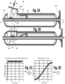
- Figure 2A illustrates the internal mechanism of the handle 100 in a sectioned plan view.
- Figure 2A illustrates the position of push button 106 in an initial state of the handle 100 while
- Figure 2B illustrates the position of the button 106 in relation to the slider rack 104 when the button 106 is fully actuated or depressed.
- buttons 106 can be applied to the button 106 so that the button 106 moves in a downward direction (arrow) relative to the axis Ld-Lp.
- Button 106 is mounted to a pivot point 112 (shown in Figure 1 ) to allow for arcuate movement of button 106 in a direction towards the longitudinal axis (or even intersecting the longitudinal axis Ld-Lp).
- a shuttle 116 is disposed partly inside button housing 106. Mounted to shuttle 116 is pin 118.
- Button 106 is provided with a slot 114 in which pin 118 is mounted for movement, such as in a side member of button 106 that may be relatively parallel with axis Ld-Lp.
- pin 118 As force is applied to button 106 to move it toward the longitudinal axis in Figure 3B , pin 118 is constrained in its motion by slot 114 to translate linearly along the longitudinal axis. As pin 118 is connected to the secondary rack 120, secondary rack 120 must move, shown here in Figure 3C . Movement of secondary rack 120 forces the primary rack 104 to also move due to the coupling of the teeth (or pawls) between the primary rack 104 and secondary rack 120.
- the embodiments described herein allow for a generally constant force applied over time (i.e., constant force rate of change in Figure 2C ) to provide a generally constant distance traveled over time (i.e., rate of change of distance in Figure 2D ).
- biasing members allow the button to return to its initial state as well as allowing a tertiary rack 122, as part of shuttle 116, to engage against the primary rack 104 to prevent a movement of primary rack 104 toward the distal end.
- Ratchet can also be utilized in place of or in addition to tertiary rack 122 to prevent this reversed movement of the outer sheath 108 toward the distal end.
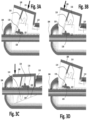
- Figures 4A and 4B illustrate yet another variation 100' of the catheter handle device usable in the delivery system 10.
- Figure 4A illustrates the complete handle with safety lock 140 in a more ergonomic design.
- the exploded view of Figure 4B shows a two-part housing (100a and 100b) that houses the button 106 connected to the housing 100' via pivot opening 106A in which a pin 106B can be inserted and supported via housings 100a and 100b.
- a ratchet 130 is provided to prevent primary rack 104 from moving distally.
- Torsion spring 132 is disposed in the housing to bias the shuttle 116 toward engagement with rack 104.
- Torsion spring 104 is disposed in the housing to bias actuator 106 towards its initial position.
- slot 114 can be configured in any shape such as, for example, linear, curvilinear or arcuate.
- applicant has devised the system 10 to achieve constant rate of change of distance in the retraction of the sheath for constant rate of force applied to actuator 106. To achieve this, a spline S ( Figure 7 ) was derived.
- the spline S in which a path (i.e., slot 114) of pin 118 must follow is defined by discrete points (p0, p1, p2, p3 ... p6) each located on respective radii (R0, R1, R2, ...
- R6 of a first arc C of ⁇ degrees with a radius R where each radii is separated by a second arc of ⁇ degrees and each point is located at a distance dn measured from a circumference of the first arc C of ⁇ degrees
- dn R- (X+n*(0.2)*(R))
- n comprises a sequence of positive integers including zero and X can be any value from 2 mm to 20 mm, while ⁇ can be from 5 to 45 degrees and ⁇ can be from 1 to 10 degrees.
- R is about 60 mm
- X is about 10 mm
- d0 is about 10 mm
- d1 is about 11.05 mm
- d2 is about 12.1 mm
- d3 is about 13.2 mm
- d4 is about 14.2 mm
- d5 is about 15.3 mm
- d6 is about 16.3 mm while ⁇ is about 12 degrees and ⁇ is about 2 degrees. It should be noted that this is but one example and that many other examples can be derived using the empirical technique and range for variables R, X, n, ⁇ and ⁇ as devised by applicant.
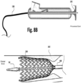
- the distal end of the medical device delivery system 10 is preferably directed into a patient via a body passageway 300.
- the medical device delivery system 10 may preferably follow along a guidewire (not shown) or travel through a previously placed guiding catheter (not shown), until the distal tip 90 is at a desired location in the body vessel 300 for treatment.
- the distal tip 90 has preferably crossed the site of a lesion or stenosis 302.
- the physician releases or removes the safety lock 140 of the handle (not shown for brevity).
- the lock may be releasable only once, or may be capable of repeatedly being engaged and released.
- Such a locking mechanism preferably resists inadvertent or accidental movement or retraction of the stent delivery system components during packaging, sterilization, shipping, storage, handling and preparation.
- the actuator 106 can be depressed such that the outer sheath 108 is retracted towards the operator.
- the use of the actuator 106 coupled to the outer sheath 108 allows precise and sensitive adjustment to pull the outer sheath 108 back slightly. This small movement exposes a small portion of the medical device, in this case a stent 200, as shown in Figure 8A .
- the handle 100 will hold the outer sheath 108 in position relative to the inner wire SO, resisting further inadvertent expansion of the stent 200.
- the physician then has the time and flexibility of procedure to selectively optimize and make any final adjustments to the position of the medical device and delivery system within the desired site, as illustrated in Figure 8A.
- the physician may continue to rotate the actuator 106 to further withdraw the outer sheath 108, as shown in Figure 8B .
- the physician may simply grasp flange 105 to pull slider rack 104 in the distal direction.
- This second mode of withdrawing the outer sheath 108 allows relatively large-scale and rapid movement, at whatever speed the physician wishes, to quickly deploy the medical device.
- the inner and outer shaft members and, strain relief and distal tip may be made of any biocompatible and suitably flexible yet sufficiently strong material, including polymers of various types. Possible selections for such materials include nylons or polyamides, polyimides, polyethylenes, polyurethanes, polyethers, polyesters, etc.
- some portion or all of the inner and/or outer shaft member may be formed of a flexible metal, including for example stainless steel or nitinol hypotube.
- the stent 200 is preferably made of any biocompatible material that is strong and rigid, including for example stainless steel, platinum, tungsten, etc.
- the components of the handle of the present invention are preferably made of a material that is strong and rigid, including for example inflexible polycarbonates, or even some metal components.
- the inner shaft member distal tip may preferably be provided with a through lumen adapted to receive a guidewire.
- a method of moving a stent to a selected location in a body vessel includes applying a generally constant force over time to an actuator in a direction intersecting the longitudinal axis to translate the outer sheath at a generally constant first rate of change of distance along the longitudinal axis towards a distal end of the delivery system to allow a portion of the self-expanding stent to be expanded into the body vessel; and subsequently pulling a flange member after desired positioning of the stent so that the outer sheath is moved relative to the inner shaft along a direction from the distal end toward a proximal end of the delivery system at a second rate of change of distance greater than the first rate of change of distance.
Description
- This application claims priority under 35 U.S.C. § 119 or the Paris Convention from
U.S. Provisional Patent Application 62/578,494 filed October 29, 2017 - It is well known to employ various intravascular endoprostheses delivered percutaneously for the treatment of diseases of various body vessels. These types of endoprosthesis are commonly referred to as "stents". A stent (which includes covered stents or stent-graft) is a generally longitudinal tubular device of biocompatible material, such as stainless steel, cobalt-chromium, nitinol or biodegradable materials, having holes or slots cut therein to define a flexible framework so they can be radially expanded, by a balloon catheter or the like, or alternately self-expanded due to its shape memory characteristic of the material within a biological vessel. The stents are usually configured as a series of hoops with each defined by cylinder-like framework. The framework is usually a series of alternating sequence of struts with a vertex between each pair of struts and configured so that the vertex of one hoop facing a vertex of the adjacent hoops may be connected together. The struts are configured to move and thereby allow the stent to be compressed or "crimped" into a smaller outer diameter so that they can be mounted inside a delivery system.
- The delivery system is used to convey the stent to a desired location for treatment, and then deploy it in position. Many such stents are resiliently compressed to a smaller initial size for containment, protection, storage and eventual delivery from inside a catheter system. Upon deployment, the stents may resiliently self-expand to a larger deployed size in some embodiments or may be expanded mechanically, such as by a balloon catheter.
- A successful example of a delivery catheter system, in this case for a self-expanding stent, is described in
U.S. Pat. No. 6,019,778 entitled "Delivery Apparatus For A Self-Expanding Stent," to Wilson et al. issued Feb. 1, 2000 . This patent generally discloses a flexible catheter system shown in a representative diagrammatic form in Figure 10 of Wilson, including coaxially arranged inner and outer catheter members, each having a hub affixed to its proximal end. The outer sheath is described in the '778 patent as an elongated tubular member having distal and proximal ends, which is made from an outer polymeric layer, an inner polymeric layer, and a braided reinforcing layer between them. The inner shaft is described in the '778 patent as being located coaxially within the outer sheath and has a flexible tapering distal end, which generally extends distally beyond the distal end of the outer sheath. The inner shaft member also is shown as including a stop which is positioned proximal from the distal end of the outer sheath. A self-expanding stent is located within the outer sheath, and is located between the stop on the inner shaft member and the outer sheath distal end. To deploy the stent the outer sheath is withdrawn by a physician in a proximal direction, while the inner shaft member is held in position. - Additional examples of different types of known self-expanding stent delivery systems are shown in
U.S. Pat. No. 4,580,568 issued to Gianturco on Apr. 8, 1986 ; as well asU.S. Pat. No. 4,732,152 issued to Wallsten et al., on Mar. 22, 1988 . - In operation, these known stent delivery systems are generally advanced within a body of a patient along a desired vascular path or other body passageway, until the stent within the catheter system is located at a desired site for treatment. While watching the relative positions of the stent and the catheter system components with respect to a stenosis on a video x-ray fluoroscopy screen, the physician holds the proximal hub attached to the inner shaft member in a fixed position with one hand, while simultaneously gently withdrawing the proximal hub attached to the outer tubular sheath with the other hand.
- For several reasons, this deployment operation may require some measure of delicate skill. For example, among these reasons is the dynamic blood flow at the desired site for treatment, which may be further disrupted by the presence of a lesion or stenosis to be treated. Another factor is the gradual resilient expansion of a stent as the outer sheath is retracted. This gradual expansion presents an opportunity for a possible reverse "watermelon-seed" phenomenon to occur. This reverse watermelon-seed phenomenon may cause the resilient stent to tend to push the outer sheath back in a proximal direction with a force that tends to change as the sheath is progressively retracted.
- As a result, the physician may need to accurately hold the two proximal hubs in a specific relative position, holding them against this expansion force, while attempting to very accurately position the stent up until contact with the anatomy. One of the possibilities that may affect the positioning of the deployed stent is that the inner shaft should preferably be held stationary in the desired position. If the physician's hand that holds the inner shaft hub does inadvertently move during deployment, it is possible that the stent may be deployed in a non-optimum position.
- Another possible factor is that the inner and outer catheter shaft members, like any other elongated object, do not have infinite column strength, which may present an opportunity for the position and movement of each proximal hub to differ from the position and movement of the respective distal ends of the inner and outer shaft members. Yet another factor is that the position of the stent may be adjusted up until the point at which a portion of the expanding portion of the stent touches the sidewalls of the body passage, so that the position of the stent should preferably be carefully adjusted until immediately before a portion of the stent touches the anatomy.
- Some known catheter systems require two-handed operation, such as those with a pair of independent hubs, one hub on each of the inner and outer shaft members, respectively. Other known catheter systems include a pistol and trigger grip, with a single mode of deployment, involving a single trigger pull to deploy the associated stent.
-
US 2012/290066A1 discloses a stent graft introducer having a stent graft releasably retained onto a deployment catheter and a sheath enclosing the stent graft. A handle assembly having a handle, a first slide and a second slide. The first slide retracts within the second slide and the second slide retracts within the handle. An actuation arrangement comprises a first longitudinal gear rack on the first slide, a second longitudinal gear rack on the second slide and a ratchet lever assembly on the handle. Actuation of the ratchet lever assembly causes the second slide to fully retract into the handle at which time the ratchet lever assembly engages the first gear rack through an aperture in the second rack and continued actuation causes retraction of the first slide thereby retracting the sheath from the pusher to expose the stent graft. -
DE 10 2005 051469A1 discloses an apparatus with a sleeve accommodating and compressing a stent during its insertion into a vessel, a handle joined to the rear of a pushing element and a guiding wire. The sleeve is connected to a serrated bar working in combination with a spring supported locking element. A spring supported lever acts on the serrated bar and the locking element in order to gradually remove the sleeve from the stent. - Applicant has devised a stent delivery system that includes a catheter tip, primary rack, and a housing. The catheter tip is coupled to an inner shaft and an outer sheath with a stent disposed between the inner shaft and the outer sheath. The inner shaft and the outer sheath extends from a distal end to a proximal end. The primary rack is connected to the outer sheath. The housing encloses a portion of the primary rack. The housing extends along a longitudinal axis from a first end to a second end. The housing includes a button and a shuttle. The button is coupled to the housing to allow for movement of the button along an arc, the button defining at least a side member generally parallel to the longitudinal axis, the side member having a slot that approximates a curve.
- The shuttle is disposed partly in the button. The shuttle has a secondary rack configured to mate with a portion of the primary rack. The shuttle has a pin extending through the shuttle and the slot so that movement of the button towards the longitudinal axis forces the primary rack to translate along the longitudinal axis due to motion of the slot of the button against the pin of the shuttle.
- In yet a further embodiment, applicant has devised a catheter system that includes an outer sheath, a primary rack and a housing. The outer sheath extends from a distal end to a proximal end. The primary rack is connected to the outer sheath. The housing encloses a portion of the primary rack. The housing extends along a longitudinal axis from a first end to a second end and includes a button coupled to the housing to allow for movement of the button along an arc. The button defines at least a side member generally parallel to the longitudinal axis. The side member has a slot that approximates a curve, and a shuttle disposed partly in the button. The shuttle has a secondary rack configured to mate with a portion of the primary rack with a pin extending through the shuttle and the slot so that movement of the button in a first direction toward the longitudinal axis forces the primary rack to translate along the longitudinal axis toward the second end due to motion of the slot of the button against the pin of the shuttle.
- A method of delivering a self-expanding stent to selected location in a body vessel (which does not form part of the present invention), can be achieved by: moving a stent to a selected location in a body vessel, the stent being disposed adjacent a catheter tip and confined between an inner shaft and an outer sheath at a distal end of a delivery system; and applying a generally constant force over time to an actuator in a direction intersecting the longitudinal axis to translate the outer sheath at a generally constant first rate of change of distance along the longitudinal axis towards a distal end of the delivery system to allow a portion of the self-expanding stent to be expanded into the body vessel; and pulling a flange member so that the outer sheath is moved relative to the inner shaft along a direction from the distal end toward a proximal end of the delivery system at a second rate of change of distance greater than the first rate of change of distance.
- For each of the embodiments described above, the following features can be utilized in various permutations with each of the embodiments. For example, the primary rack includes a flanged tab at the second end of the housing; the button is mounted to a pivot in the housing to allow for arcuate movement of the button and a tertiary rack is coupled to the shuttle to prevent movement of the primary rack along the longitudinal axis toward the first end when the tertiary rack is engaged with the primary rack. A ratchet is disposed in the housing to prevent movement of the primary rack along the longitudinal axis toward the first end; a safety pin is disposed between the button and the shuttle to prevent actuation of the button; a first biasing member is coupled to the button to bias the button in a direction opposite the first direction of the button; a second biasing member is coupled to the shuttle to bias the shuttle in the first direction of the button; the housing may include two halves that are generally symmetrical with respect to the longitudinal axis; the slot defines a spline so that a predetermined amount of force over time applied to the button results in a generally constant displacement over time of the primary rack. As well, the spline is defined by discrete points each located on respective radii of a first arc of α degrees with a radius R where each radii is separated by a second arc of β degrees and each point is located at a distance d measured from a circumference of the first arc of a degrees where dn =R- (X+n(0.2)(R)) where n may be a sequence of positive integers including zero and X can be any value from 2 mm to 20 mm. For example, α may be about 12 degrees and β may be about 2 degrees and radius R may be about 60 millimeters.
- These and other embodiments, features and advantages will become apparent to those skilled in the art when taken with reference to the following more detailed description of the exemplary embodiments of the invention in conjunction with the accompanying drawings that are first briefly described. As well, it is intended that these embodiments, features and advantages may be claimed in this or additional applications for patents.
- The accompanying drawings, which are incorporated herein and constitute part of this specification, illustrate presently preferred embodiments of the invention, and, together with the general description given above and the detailed description given below, serve to explain features of the invention (wherein like numerals represent like elements), in which:
-
FIG. 1 illustrates a perspective view of a handle according to an embodiment; -
FIGS. 2A and 2B illustrate sectioned side views of an embodiment of the handle inFigure 1 during an initial state and a final state; -
FIGS. 2C and 2D illustrate respectively the input force over time and resulting distance traveled over time typical of a handle according toFigure 1 ; -
FIGS. 3A, 3B, 3C, and 3D illustrate close-up view of the operation of the handle inFigure 1 ; -
FIGS. 4A and 4B illustrate yet another embodiment of the handle inFigure 1 with the principles ofFigures 1-3 ; -
FIG. 5 illustrates a close-up perspective of the handle with the principles ofFigures 1-3 ; -
FIG. 6 illustrates a close-up plan view of a section of the embodiment ofFigure 3 ; -
FIG. 7 illustrates a spline that define the path of the pin in the embodiments described and illustrated herein; and -
FIGS. 8A and8B illustrate the operation of the system, according to an embodiment. - The following detailed description should be read with reference to the drawings, in which like elements in different drawings are identically numbered. The drawings, which are not necessarily to scale, depict selected embodiments and are not intended to limit the scope of the invention. The detailed description illustrates by way of example, not by way of limitation, the principles of the invention. This description will clearly enable one skilled in the art to make and use the invention, and describes several embodiments, adaptations, variations, alternatives and uses of the invention, including what is presently believed to be the best mode of carrying out the invention.
- As used herein, the terms "about" or "approximately" for any numerical values or ranges indicate a suitable dimensional tolerance that allows the part or collection of components to function for its intended purpose as described herein. More specifically, "about" or "approximately" may refer to the range of values ±10% of the recited value, e.g. "about 90%" may refer to the range of values from 81% to 99%. In addition, as used herein, the terms "patient," "host," "user," and "subject" refer to any human or animal subject and are not intended to limit the systems or methods to human use, although use of the subject invention in a human patient represents a preferred embodiment. The term "stent" is intended to encompass an uncovered framework as well as one that is covered by a suitable material (e.g., stent-graft). The term "proximal" is used to denote the location closer to the operator and "distal" is used to denote a location further away from the operator or the health care provider.
- Referring now to the figures wherein like numerals indicate the same element throughout the views, there is shown in
Figure 1 a portion of thedelivery system 10 in the form of a handle that defines ahousing 100. Thehousing 100 extends along a longitudinal axis Ld-Lp from a proximal end to a distal end. Thehousing 100 provides aslot 101 that extends along a portion of the longitudinal axis Ld-Lp. Anouter sheath 108 is configured for movement along the longitudinal axis Ld-Lp by being coupled to aslider rack 104 disposed in and throughhousing 100. Theslider rack 104 is attached to aflanged slider tab 105 so that theentire rack 104 can be pulled toward the proximal end very quickly. A luer fitting 102 is provided at the proximal end Lp. Apush button 106 can be actuated by a finger, preferably a thumb of the operator to allow for slow retraction of thesheath 108 during deployment of the stent. -
Figure 2A illustrates the internal mechanism of thehandle 100 in a sectioned plan view. In particular,Figure 2A illustrates the position ofpush button 106 in an initial state of thehandle 100 whileFigure 2B illustrates the position of thebutton 106 in relation to theslider rack 104 when thebutton 106 is fully actuated or depressed. - Referring to
Figure 3A , forces (arrow) can be applied to thebutton 106 so that thebutton 106 moves in a downward direction (arrow) relative to the axis Ld-Lp.Button 106 is mounted to a pivot point 112 (shown inFigure 1 ) to allow for arcuate movement ofbutton 106 in a direction towards the longitudinal axis (or even intersecting the longitudinal axis Ld-Lp). Ashuttle 116 is disposed partly insidebutton housing 106. Mounted toshuttle 116 ispin 118.Button 106 is provided with aslot 114 in whichpin 118 is mounted for movement, such as in a side member ofbutton 106 that may be relatively parallel with axis Ld-Lp. As force is applied tobutton 106 to move it toward the longitudinal axis inFigure 3B ,pin 118 is constrained in its motion byslot 114 to translate linearly along the longitudinal axis. Aspin 118 is connected to thesecondary rack 120,secondary rack 120 must move, shown here inFigure 3C . Movement ofsecondary rack 120 forces theprimary rack 104 to also move due to the coupling of the teeth (or pawls) between theprimary rack 104 andsecondary rack 120. Of note is that the embodiments described herein allow for a generally constant force applied over time (i.e., constant force rate of change inFigure 2C ) to provide a generally constant distance traveled over time (i.e., rate of change of distance inFigure 2D ). Once force is released, biasing members (shown elsewhere) allow the button to return to its initial state as well as allowing atertiary rack 122, as part ofshuttle 116, to engage against theprimary rack 104 to prevent a movement ofprimary rack 104 toward the distal end. Ratchet (shown elsewhere) can also be utilized in place of or in addition totertiary rack 122 to prevent this reversed movement of theouter sheath 108 toward the distal end. -
Figures 4A and 4B illustrate yet another variation 100' of the catheter handle device usable in thedelivery system 10. In particular,Figure 4A illustrates the complete handle withsafety lock 140 in a more ergonomic design. In addition to the common components illustrated earlier (referenced with the same reference numerals) the exploded view ofFigure 4B shows a two-part housing (100a and 100b) that houses thebutton 106 connected to the housing 100' viapivot opening 106A in which a pin 106B can be inserted and supported via housings 100a and 100b. As shown also inFigures 5 and6 , aratchet 130 is provided to preventprimary rack 104 from moving distally.Torsion spring 132 is disposed in the housing to bias theshuttle 116 toward engagement withrack 104.Torsion spring 104 is disposed in the housing tobias actuator 106 towards its initial position. As in theembodiment 100,slot 114 can be configured in any shape such as, for example, linear, curvilinear or arcuate. In the embodiments illustrated and described here, applicant has devised thesystem 10 to achieve constant rate of change of distance in the retraction of the sheath for constant rate of force applied toactuator 106. To achieve this, a spline S (Figure 7 ) was derived. - As shown in
Figure 7 , the spline S in which a path (i.e., slot 114) ofpin 118 must follow is defined by discrete points (p0, p1, p2, p3 ... p6) each located on respective radii (R0, R1, R2, ... R6) of a first arc C of α degrees with a radius R where each radii is separated by a second arc of β degrees and each point is located at a distance dn measured from a circumference of the first arc C of α degrees where dn =R- (X+n*(0.2)*(R)) where n comprises a sequence of positive integers including zero and X can be any value from 2 mm to 20 mm, while α can be from 5 to 45 degrees and β can be from 1 to 10 degrees. In the example described and illustrated here, R is about 60 mm, X is about 10 mm; d0 is about 10 mm; d1 is about 11.05 mm; d2 is about 12.1 mm; d3 is about 13.2 mm; d4 is about 14.2 mm; d5 is about 15.3 mm and d6 is about 16.3 mm while α is about 12 degrees and β is about 2 degrees. It should be noted that this is but one example and that many other examples can be derived using the empirical technique and range for variables R, X, n, α and β as devised by applicant. - In operation as schematically indicated in
Figures 8A and8B , the distal end of the medicaldevice delivery system 10 is preferably directed into a patient via abody passageway 300. The medicaldevice delivery system 10 may preferably follow along a guidewire (not shown) or travel through a previously placed guiding catheter (not shown), until thedistal tip 90 is at a desired location in thebody vessel 300 for treatment. As shown inFigure 8B , thedistal tip 90 has preferably crossed the site of a lesion orstenosis 302. When the device is properly in an initial position (Figure 8A ), the physician releases or removes thesafety lock 140 of the handle (not shown for brevity). The lock may be releasable only once, or may be capable of repeatedly being engaged and released. Such a locking mechanism preferably resists inadvertent or accidental movement or retraction of the stent delivery system components during packaging, sterilization, shipping, storage, handling and preparation. - After the lock is released, the
actuator 106 can be depressed such that theouter sheath 108 is retracted towards the operator. The use of theactuator 106 coupled to theouter sheath 108 allows precise and sensitive adjustment to pull theouter sheath 108 back slightly. This small movement exposes a small portion of the medical device, in this case astent 200, as shown inFigure 8A . In this configuration, thehandle 100 will hold theouter sheath 108 in position relative to the inner wire SO, resisting further inadvertent expansion of thestent 200. The physician then has the time and flexibility of procedure to selectively optimize and make any final adjustments to the position of the medical device and delivery system within the desired site, as illustrated inFigure 8A This precise adjustment of the position of thestent 200, before any portion of thestent 200 touches the body passage orvessel 300 in a manner that might inhibit further positional adjustment, is preferable. - When the physician is satisfied with the positioning, as it appears on a fluoroscopic x-ray video screen, the physician may continue to rotate the
actuator 106 to further withdraw theouter sheath 108, as shown inFigure 8B . - Upon initial contact of the
stent 200 with the vessel wall, or when the stent is 200 expanded sufficiently to independently hold its position, or at any desired point, the physician may simply graspflange 105 to pullslider rack 104 in the distal direction. This second mode of withdrawing theouter sheath 108 allows relatively large-scale and rapid movement, at whatever speed the physician wishes, to quickly deploy the medical device. - Various materials may be selected for the components of the present invention, including any material having the desirable performance characteristics. In the particular embodiment shown in the drawings, the inner and outer shaft members and, strain relief and distal tip may be made of any biocompatible and suitably flexible yet sufficiently strong material, including polymers of various types. Possible selections for such materials include nylons or polyamides, polyimides, polyethylenes, polyurethanes, polyethers, polyesters, etc. In the alternative, some portion or all of the inner and/or outer shaft member may be formed of a flexible metal, including for example stainless steel or nitinol hypotube. The
stent 200 is preferably made of any biocompatible material that is strong and rigid, including for example stainless steel, platinum, tungsten, etc. The components of the handle of the present invention are preferably made of a material that is strong and rigid, including for example inflexible polycarbonates, or even some metal components. In addition, the inner shaft member distal tip may preferably be provided with a through lumen adapted to receive a guidewire. - Of course, many different variations are included within the scope of the present invention. Some of these variations or alternative embodiments include any possible arrangement of sizes, materials, and designs within the scope of the claims.
- By virtue of the disclosure provided herein, a method of moving a stent to a selected location in a body vessel is provided. The stent is disposed adjacent a catheter tip and confined between an inner shaft and an outer sheath at a distal end of a delivery system The method includes applying a generally constant force over time to an actuator in a direction intersecting the longitudinal axis to translate the outer sheath at a generally constant first rate of change of distance along the longitudinal axis towards a distal end of the delivery system to allow a portion of the self-expanding stent to be expanded into the body vessel; and subsequently pulling a flange member after desired positioning of the stent so that the outer sheath is moved relative to the inner shaft along a direction from the distal end toward a proximal end of the delivery system at a second rate of change of distance greater than the first rate of change of distance.
Claims (13)
- A catheter system comprising:an outer sheath (108) extending from a distal end to a proximal end;a primary rack (104) connected to the outer sheath (108); anda housing (100) enclosing a portion of the primary rack (104), the housing (100) extending along a longitudinal axis (Ld-Lp) from a first end to a second end, the housing (100) includes:a button (106) coupled to the housing (100) to allow for movement of the button (106) along an arc, the button defining at least a side member generally parallel to the longitudinal axis, characterized in that the side member has a slot (114) that approximates a curve; anda shuttle (116) disposed partly in the button (106), the shuttle (116) having a secondary rack (120) configured to mate with a portion of the primary rack (104), the shuttle (116) having a pin (118) extending through the shuttle (116) and the slot (114) so that movement of the button (106) in a first direction toward the longitudinal axis forces the primary rack (104) to translate along the longitudinal axis toward the second end due to motion of the slot (114) of the button (106) against the pin (118) of the shuttle (116).
- The system of claim 1, wherein the primary rack (104) includes a flanged tab at the second end of the housing (100).
- The system of claim 1, wherein the button (106) is mounted to a pivot (112) in the housing (100) to allow for arcuate movement of the button (106).
- The system of claim 1, wherein a tertiary rack (122) is coupled to the shuttle (116) to prevent movement of the primary rack (104) along the longitudinal axis toward the first end when the tertiary rack (122) is engaged with the primary rack (104).
- The system of claim 1, wherein a ratchet (130) is disposed in the housing (100) to prevent movement of the primary rack (104) along the longitudinal axis toward the first end.
- The system of claim 1, wherein a safety pin is disposed between the button (106) and the shuttle (116) to prevent actuation of the button (106).
- The system of claim 1, wherein a first biasing member (104) is coupled to the button (106) to bias the button in a direction opposite the first direction of the button.
- The system of claim 1, wherein a second biasing member (132) is coupled to the shuttle (116) to bias the shuttle in the first direction of the button.
- The system of claim 1, wherein the housing (100) comprises two halves that are generally symmetrical with respect to the longitudinal axis.
- The system of claim 1, wherein the slot (114) defines a spline (S) so that a predetermined amount of force over time applied to the button (106) results in a generally constant displacement over time of the primary rack (104).
- The system of claim 10, wherein the spline (S) is defined by discrete points each located on respective radii of a first arc of α degrees with a radius R where each radii is separated by a second arc of β degrees and each point is located at a distance d measured from a circumference of the first arc of α degrees where dn=R- (X+n(0.2)(R)) where n comprises a sequence of positive integers including zero and X can be any value from 2 mm to 20 mm.
- The system of claim 11, wherein α comprises about 12 degrees and β comprises about 2 degrees.
- The system of claim 12, wherein radius R comprises about 60 millimeters.
Applications Claiming Priority (2)
| Application Number | Priority Date | Filing Date | Title |
|---|---|---|---|
| US201762578494P | 2017-10-29 | 2017-10-29 | |
| PCT/IB2018/001308 WO2019081977A1 (en) | 2017-10-29 | 2018-10-24 | Stent delivery catheter system with slow speed control via pin and slot with fast speed control tab |
Publications (4)
| Publication Number | Publication Date |
|---|---|
| EP3700476A1 EP3700476A1 (en) | 2020-09-02 |
| EP3700476B1 true EP3700476B1 (en) | 2023-06-07 |
| EP3700476C0 EP3700476C0 (en) | 2023-06-07 |
| EP3700476B8 EP3700476B8 (en) | 2023-12-06 |
Family
ID=65010800
Family Applications (1)
| Application Number | Title | Priority Date | Filing Date |
|---|---|---|---|
| EP18833109.4A Active EP3700476B8 (en) | 2017-10-29 | 2018-10-24 | Stent delivery catheter system with slow speed control via pin and slot with fast speed control tab |
Country Status (12)
| Country | Link |
|---|---|
| US (1) | US10893965B2 (en) |
| EP (1) | EP3700476B8 (en) |
| JP (2) | JP7025540B2 (en) |
| KR (1) | KR102591543B1 (en) |
| CN (2) | CN115192284A (en) |
| AU (1) | AU2018357192A1 (en) |
| BR (1) | BR112020008496A2 (en) |
| CA (1) | CA3079366C (en) |
| ES (1) | ES2947057T3 (en) |
| IL (1) | IL274080A (en) |
| MX (1) | MX2020004314A (en) |
| WO (1) | WO2019081977A1 (en) |
Families Citing this family (2)
| Publication number | Priority date | Publication date | Assignee | Title |
|---|---|---|---|---|
| DE102021132097A1 (en) * | 2021-12-06 | 2023-06-07 | Optimed Medizinische Instrumente Gmbh | Hand unit for delivering and releasing an implant |
| WO2023173117A2 (en) * | 2022-03-11 | 2023-09-14 | Salvus Medical Llc | Locking mechanism for cannulized surgical instruments |
Family Cites Families (16)
| Publication number | Priority date | Publication date | Assignee | Title |
|---|---|---|---|---|
| US4580568A (en) | 1984-10-01 | 1986-04-08 | Cook, Incorporated | Percutaneous endovascular stent and method for insertion thereof |
| IT1186142B (en) | 1984-12-05 | 1987-11-18 | Medinvent Sa | TRANSLUMINAL IMPLANTATION DEVICE |
| US6019778A (en) | 1998-03-13 | 2000-02-01 | Cordis Corporation | Delivery apparatus for a self-expanding stent |
| DE102005051469B4 (en) * | 2005-10-21 | 2011-07-28 | JOTEC GmbH, 72379 | Device for introducing a self-expanding stent into a body vessel |
| US7896911B2 (en) * | 2007-12-12 | 2011-03-01 | Innovasc Llc | Device and method for tacking plaque to blood vessel wall |
| US9339631B2 (en) * | 2009-09-25 | 2016-05-17 | Boston Scientific Scimed, Inc. | Locking mechanism for a medical device |
| CN103079500B (en) | 2010-09-01 | 2016-09-21 | 美敦力公司 | The deploying handles of one-handed performance |
| AU2011202174B1 (en) * | 2011-05-11 | 2011-08-25 | Cook Medical Technologies Llc | Introducer with ratchet handle drive |
| EP3733134A1 (en) | 2012-01-25 | 2020-11-04 | Intact Vascular, Inc. | Endoluminal device |
| EP2865319B1 (en) | 2013-10-25 | 2017-06-14 | Cook Medical Technologies LLC | Deflectable Access Sheath Handle |
| US9192500B1 (en) * | 2015-01-29 | 2015-11-24 | Intact Vascular, Inc. | Delivery device and method of delivery |
| CN106175985B (en) * | 2015-04-29 | 2018-08-24 | 上海微创心通医疗科技有限公司 | Drive handle for delivering an implant and delivery system |
| CN204971727U (en) * | 2015-07-22 | 2016-01-20 | 南京微创医学科技股份有限公司 | Ware is put into to gun type support that can reciprocate |
| US10137006B2 (en) * | 2016-01-28 | 2018-11-27 | Warsaw Orthopedic, Inc. | Geared cam expandable interbody implant and method of implanting same |
| CN106214298B (en) * | 2016-08-15 | 2018-08-17 | 苏州天鸿盛捷医疗器械有限公司 | A kind of bracket conveyer |
| CN106166092B (en) * | 2016-08-31 | 2018-09-14 | 广州爱锘德医疗器械有限公司 | Lift threaded fusion cage and the operator for driving lifting threaded fusion cage |
-
2018
- 2018-10-24 JP JP2020522732A patent/JP7025540B2/en active Active
- 2018-10-24 CA CA3079366A patent/CA3079366C/en active Active
- 2018-10-24 EP EP18833109.4A patent/EP3700476B8/en active Active
- 2018-10-24 US US16/169,793 patent/US10893965B2/en active Active
- 2018-10-24 CN CN202210740530.4A patent/CN115192284A/en active Pending
- 2018-10-24 BR BR112020008496-4A patent/BR112020008496A2/en unknown
- 2018-10-24 MX MX2020004314A patent/MX2020004314A/en unknown
- 2018-10-24 WO PCT/IB2018/001308 patent/WO2019081977A1/en active Application Filing
- 2018-10-24 ES ES18833109T patent/ES2947057T3/en active Active
- 2018-10-24 CN CN201880070894.8A patent/CN111263623B/en active Active
- 2018-10-24 KR KR1020207012326A patent/KR102591543B1/en active IP Right Grant
- 2018-10-24 AU AU2018357192A patent/AU2018357192A1/en active Pending
-
2020
- 2020-04-20 IL IL274080A patent/IL274080A/en unknown
-
2022
- 2022-02-10 JP JP2022019230A patent/JP7187722B2/en active Active
Also Published As
| Publication number | Publication date |
|---|---|
| IL274080A (en) | 2020-06-30 |
| CN111263623B (en) | 2022-07-19 |
| JP2022081485A (en) | 2022-05-31 |
| JP2021500949A (en) | 2021-01-14 |
| MX2020004314A (en) | 2020-08-13 |
| BR112020008496A2 (en) | 2020-10-20 |
| JP7025540B2 (en) | 2022-02-24 |
| WO2019081977A1 (en) | 2019-05-02 |
| CN111263623A (en) | 2020-06-09 |
| KR102591543B1 (en) | 2023-10-18 |
| KR20200083468A (en) | 2020-07-08 |
| US10893965B2 (en) | 2021-01-19 |
| CA3079366C (en) | 2023-03-14 |
| CA3079366A1 (en) | 2019-05-02 |
| AU2018357192A1 (en) | 2020-04-30 |
| EP3700476B8 (en) | 2023-12-06 |
| EP3700476A1 (en) | 2020-09-02 |
| US20190125564A1 (en) | 2019-05-02 |
| JP7187722B2 (en) | 2022-12-12 |
| CN115192284A (en) | 2022-10-18 |
| EP3700476C0 (en) | 2023-06-07 |
| ES2947057T3 (en) | 2023-08-01 |
Similar Documents
| Publication | Publication Date | Title |
|---|---|---|
| EP1380271B1 (en) | Locking handle deployment mechanism for medical device | |
| CA3062043C (en) | Stent delivery catheter with fast slider and slow thumbwheel control | |
| JP7187722B2 (en) | stent delivery system | |
| US10925763B2 (en) | Stent delivery catheter with convertible living-hinge for slow to fast retraction | |
| CA3062045C (en) | Stent delivery catheter with fine thumbwheel control and fast crank handle |
Legal Events
| Date | Code | Title | Description |
|---|---|---|---|
| STAA | Information on the status of an ep patent application or granted ep patent |
Free format text: STATUS: UNKNOWN |
|
| STAA | Information on the status of an ep patent application or granted ep patent |
Free format text: STATUS: THE INTERNATIONAL PUBLICATION HAS BEEN MADE |
|
| PUAI | Public reference made under article 153(3) epc to a published international application that has entered the european phase |
Free format text: ORIGINAL CODE: 0009012 |
|
| STAA | Information on the status of an ep patent application or granted ep patent |
Free format text: STATUS: REQUEST FOR EXAMINATION WAS MADE |
|
| 17P | Request for examination filed |
Effective date: 20200429 |
|
| AK | Designated contracting states |
Kind code of ref document: A1 Designated state(s): AL AT BE BG CH CY CZ DE DK EE ES FI FR GB GR HR HU IE IS IT LI LT LU LV MC MK MT NL NO PL PT RO RS SE SI SK SM TR |
|
| AX | Request for extension of the european patent |
Extension state: BA ME |
|
| DAV | Request for validation of the european patent (deleted) | ||
| DAX | Request for extension of the european patent (deleted) | ||
| GRAP | Despatch of communication of intention to grant a patent |
Free format text: ORIGINAL CODE: EPIDOSNIGR1 |
|
| STAA | Information on the status of an ep patent application or granted ep patent |
Free format text: STATUS: GRANT OF PATENT IS INTENDED |
|
| INTG | Intention to grant announced |
Effective date: 20221209 |
|
| GRAS | Grant fee paid |
Free format text: ORIGINAL CODE: EPIDOSNIGR3 |
|
| GRAA | (expected) grant |
Free format text: ORIGINAL CODE: 0009210 |
|
| STAA | Information on the status of an ep patent application or granted ep patent |
Free format text: STATUS: THE PATENT HAS BEEN GRANTED |
|
| AK | Designated contracting states |
Kind code of ref document: B1 Designated state(s): AL AT BE BG CH CY CZ DE DK EE ES FI FR GB GR HR HU IE IS IT LI LT LU LV MC MK MT NL NO PL PT RO RS SE SI SK SM TR |
|
| REG | Reference to a national code |
Ref country code: GB Ref legal event code: FG4D |
|
| REG | Reference to a national code |
Ref country code: CH Ref legal event code: EP Ref country code: AT Ref legal event code: REF Ref document number: 1572615 Country of ref document: AT Kind code of ref document: T Effective date: 20230615 Ref country code: DE Ref legal event code: R096 Ref document number: 602018051454 Country of ref document: DE |
|
| RAP2 | Party data changed (patent owner data changed or rights of a patent transferred) |
Owner name: CORDIS US CORP. |
|
| REG | Reference to a national code |
Ref country code: ES Ref legal event code: FG2A Ref document number: 2947057 Country of ref document: ES Kind code of ref document: T3 Effective date: 20230801 |
|
| U01 | Request for unitary effect filed |
Effective date: 20230707 |
|
| U07 | Unitary effect registered |
Designated state(s): AT BE BG DE DK EE FI FR IT LT LU LV MT NL PT SE SI Effective date: 20230720 |
|
| REG | Reference to a national code |
Ref country code: LT Ref legal event code: MG9D |
|
| PG25 | Lapsed in a contracting state [announced via postgrant information from national office to epo] |
Ref country code: NO Free format text: LAPSE BECAUSE OF FAILURE TO SUBMIT A TRANSLATION OF THE DESCRIPTION OR TO PAY THE FEE WITHIN THE PRESCRIBED TIME-LIMIT Effective date: 20230907 |
|
| REG | Reference to a national code |
Ref country code: CH Ref legal event code: PK Free format text: BERICHTIGUNG B8 |
|
| PG25 | Lapsed in a contracting state [announced via postgrant information from national office to epo] |
Ref country code: RS Free format text: LAPSE BECAUSE OF FAILURE TO SUBMIT A TRANSLATION OF THE DESCRIPTION OR TO PAY THE FEE WITHIN THE PRESCRIBED TIME-LIMIT Effective date: 20230607 Ref country code: HR Free format text: LAPSE BECAUSE OF FAILURE TO SUBMIT A TRANSLATION OF THE DESCRIPTION OR TO PAY THE FEE WITHIN THE PRESCRIBED TIME-LIMIT Effective date: 20230607 Ref country code: GR Free format text: LAPSE BECAUSE OF FAILURE TO SUBMIT A TRANSLATION OF THE DESCRIPTION OR TO PAY THE FEE WITHIN THE PRESCRIBED TIME-LIMIT Effective date: 20230908 |
|
| U20 | Renewal fee paid [unitary effect] |
Year of fee payment: 6 Effective date: 20231027 |
|
| PG25 | Lapsed in a contracting state [announced via postgrant information from national office to epo] |
Ref country code: SK Free format text: LAPSE BECAUSE OF FAILURE TO SUBMIT A TRANSLATION OF THE DESCRIPTION OR TO PAY THE FEE WITHIN THE PRESCRIBED TIME-LIMIT Effective date: 20230607 |
|
| PGFP | Annual fee paid to national office [announced via postgrant information from national office to epo] |
Ref country code: GB Payment date: 20231027 Year of fee payment: 6 |
|
| PGFP | Annual fee paid to national office [announced via postgrant information from national office to epo] |
Ref country code: ES Payment date: 20231102 Year of fee payment: 6 |
|
| PG25 | Lapsed in a contracting state [announced via postgrant information from national office to epo] |
Ref country code: IS Free format text: LAPSE BECAUSE OF FAILURE TO SUBMIT A TRANSLATION OF THE DESCRIPTION OR TO PAY THE FEE WITHIN THE PRESCRIBED TIME-LIMIT Effective date: 20231007 |
|
| PG25 | Lapsed in a contracting state [announced via postgrant information from national office to epo] |
Ref country code: SM Free format text: LAPSE BECAUSE OF FAILURE TO SUBMIT A TRANSLATION OF THE DESCRIPTION OR TO PAY THE FEE WITHIN THE PRESCRIBED TIME-LIMIT Effective date: 20230607 Ref country code: SK Free format text: LAPSE BECAUSE OF FAILURE TO SUBMIT A TRANSLATION OF THE DESCRIPTION OR TO PAY THE FEE WITHIN THE PRESCRIBED TIME-LIMIT Effective date: 20230607 Ref country code: RO Free format text: LAPSE BECAUSE OF FAILURE TO SUBMIT A TRANSLATION OF THE DESCRIPTION OR TO PAY THE FEE WITHIN THE PRESCRIBED TIME-LIMIT Effective date: 20230607 Ref country code: IS Free format text: LAPSE BECAUSE OF FAILURE TO SUBMIT A TRANSLATION OF THE DESCRIPTION OR TO PAY THE FEE WITHIN THE PRESCRIBED TIME-LIMIT Effective date: 20231007 Ref country code: CZ Free format text: LAPSE BECAUSE OF FAILURE TO SUBMIT A TRANSLATION OF THE DESCRIPTION OR TO PAY THE FEE WITHIN THE PRESCRIBED TIME-LIMIT Effective date: 20230607 |
|
| PGFP | Annual fee paid to national office [announced via postgrant information from national office to epo] |
Ref country code: CH Payment date: 20231102 Year of fee payment: 6 |
|
| PG25 | Lapsed in a contracting state [announced via postgrant information from national office to epo] |
Ref country code: PL Free format text: LAPSE BECAUSE OF FAILURE TO SUBMIT A TRANSLATION OF THE DESCRIPTION OR TO PAY THE FEE WITHIN THE PRESCRIBED TIME-LIMIT Effective date: 20230607 |
|
| PLBE | No opposition filed within time limit |
Free format text: ORIGINAL CODE: 0009261 |
|
| STAA | Information on the status of an ep patent application or granted ep patent |
Free format text: STATUS: NO OPPOSITION FILED WITHIN TIME LIMIT |