EP3107142B1 - Batteriezelle mit asymmetrischer und gekerbter struktur - Google Patents
Batteriezelle mit asymmetrischer und gekerbter struktur Download PDFInfo
- Publication number
- EP3107142B1 EP3107142B1 EP14885986.1A EP14885986A EP3107142B1 EP 3107142 B1 EP3107142 B1 EP 3107142B1 EP 14885986 A EP14885986 A EP 14885986A EP 3107142 B1 EP3107142 B1 EP 3107142B1
- Authority
- EP
- European Patent Office
- Prior art keywords
- unit cell
- battery cell
- battery
- cell
- unit
- Prior art date
- Legal status (The legal status is an assumption and is not a legal conclusion. Google has not performed a legal analysis and makes no representation as to the accuracy of the status listed.)
- Active
Links
Images





Classifications
-
- H—ELECTRICITY
- H01—ELECTRIC ELEMENTS
- H01M—PROCESSES OR MEANS, e.g. BATTERIES, FOR THE DIRECT CONVERSION OF CHEMICAL ENERGY INTO ELECTRICAL ENERGY
- H01M10/00—Secondary cells; Manufacture thereof
- H01M10/04—Construction or manufacture in general
- H01M10/0436—Small-sized flat cells or batteries for portable equipment
-
- H—ELECTRICITY
- H01—ELECTRIC ELEMENTS
- H01M—PROCESSES OR MEANS, e.g. BATTERIES, FOR THE DIRECT CONVERSION OF CHEMICAL ENERGY INTO ELECTRICAL ENERGY
- H01M50/00—Constructional details or processes of manufacture of the non-active parts of electrochemical cells other than fuel cells, e.g. hybrid cells
- H01M50/50—Current conducting connections for cells or batteries
- H01M50/543—Terminals
-
- H—ELECTRICITY
- H01—ELECTRIC ELEMENTS
- H01M—PROCESSES OR MEANS, e.g. BATTERIES, FOR THE DIRECT CONVERSION OF CHEMICAL ENERGY INTO ELECTRICAL ENERGY
- H01M10/00—Secondary cells; Manufacture thereof
- H01M10/04—Construction or manufacture in general
- H01M10/0413—Large-sized flat cells or batteries for motive or stationary systems with plate-like electrodes
-
- H—ELECTRICITY
- H01—ELECTRIC ELEMENTS
- H01M—PROCESSES OR MEANS, e.g. BATTERIES, FOR THE DIRECT CONVERSION OF CHEMICAL ENERGY INTO ELECTRICAL ENERGY
- H01M10/00—Secondary cells; Manufacture thereof
- H01M10/05—Accumulators with non-aqueous electrolyte
- H01M10/052—Li-accumulators
- H01M10/0525—Rocking-chair batteries, i.e. batteries with lithium insertion or intercalation in both electrodes; Lithium-ion batteries
-
- H—ELECTRICITY
- H01—ELECTRIC ELEMENTS
- H01M—PROCESSES OR MEANS, e.g. BATTERIES, FOR THE DIRECT CONVERSION OF CHEMICAL ENERGY INTO ELECTRICAL ENERGY
- H01M10/00—Secondary cells; Manufacture thereof
- H01M10/05—Accumulators with non-aqueous electrolyte
- H01M10/058—Construction or manufacture
-
- H—ELECTRICITY
- H01—ELECTRIC ELEMENTS
- H01M—PROCESSES OR MEANS, e.g. BATTERIES, FOR THE DIRECT CONVERSION OF CHEMICAL ENERGY INTO ELECTRICAL ENERGY
- H01M10/00—Secondary cells; Manufacture thereof
- H01M10/05—Accumulators with non-aqueous electrolyte
- H01M10/058—Construction or manufacture
- H01M10/0583—Construction or manufacture of accumulators with folded construction elements except wound ones, i.e. folded positive or negative electrodes or separators, e.g. with "Z"-shaped electrodes or separators
-
- H—ELECTRICITY
- H01—ELECTRIC ELEMENTS
- H01M—PROCESSES OR MEANS, e.g. BATTERIES, FOR THE DIRECT CONVERSION OF CHEMICAL ENERGY INTO ELECTRICAL ENERGY
- H01M10/00—Secondary cells; Manufacture thereof
- H01M10/05—Accumulators with non-aqueous electrolyte
- H01M10/058—Construction or manufacture
- H01M10/0585—Construction or manufacture of accumulators having only flat construction elements, i.e. flat positive electrodes, flat negative electrodes and flat separators
-
- H—ELECTRICITY
- H01—ELECTRIC ELEMENTS
- H01M—PROCESSES OR MEANS, e.g. BATTERIES, FOR THE DIRECT CONVERSION OF CHEMICAL ENERGY INTO ELECTRICAL ENERGY
- H01M10/00—Secondary cells; Manufacture thereof
- H01M10/05—Accumulators with non-aqueous electrolyte
- H01M10/058—Construction or manufacture
- H01M10/0587—Construction or manufacture of accumulators having only wound construction elements, i.e. wound positive electrodes, wound negative electrodes and wound separators
-
- H—ELECTRICITY
- H01—ELECTRIC ELEMENTS
- H01M—PROCESSES OR MEANS, e.g. BATTERIES, FOR THE DIRECT CONVERSION OF CHEMICAL ENERGY INTO ELECTRICAL ENERGY
- H01M10/00—Secondary cells; Manufacture thereof
- H01M10/60—Heating or cooling; Temperature control
- H01M10/65—Means for temperature control structurally associated with the cells
- H01M10/655—Solid structures for heat exchange or heat conduction
- H01M10/6553—Terminals or leads
-
- H—ELECTRICITY
- H01—ELECTRIC ELEMENTS
- H01M—PROCESSES OR MEANS, e.g. BATTERIES, FOR THE DIRECT CONVERSION OF CHEMICAL ENERGY INTO ELECTRICAL ENERGY
- H01M50/00—Constructional details or processes of manufacture of the non-active parts of electrochemical cells other than fuel cells, e.g. hybrid cells
- H01M50/10—Primary casings; Jackets or wrappings
- H01M50/102—Primary casings; Jackets or wrappings characterised by their shape or physical structure
- H01M50/105—Pouches or flexible bags
-
- H—ELECTRICITY
- H01—ELECTRIC ELEMENTS
- H01M—PROCESSES OR MEANS, e.g. BATTERIES, FOR THE DIRECT CONVERSION OF CHEMICAL ENERGY INTO ELECTRICAL ENERGY
- H01M50/00—Constructional details or processes of manufacture of the non-active parts of electrochemical cells other than fuel cells, e.g. hybrid cells
- H01M50/10—Primary casings; Jackets or wrappings
- H01M50/172—Arrangements of electric connectors penetrating the casing
- H01M50/174—Arrangements of electric connectors penetrating the casing adapted for the shape of the cells
- H01M50/178—Arrangements of electric connectors penetrating the casing adapted for the shape of the cells for pouch or flexible bag cells
-
- H—ELECTRICITY
- H01—ELECTRIC ELEMENTS
- H01M—PROCESSES OR MEANS, e.g. BATTERIES, FOR THE DIRECT CONVERSION OF CHEMICAL ENERGY INTO ELECTRICAL ENERGY
- H01M50/00—Constructional details or processes of manufacture of the non-active parts of electrochemical cells other than fuel cells, e.g. hybrid cells
- H01M50/20—Mountings; Secondary casings or frames; Racks, modules or packs; Suspension devices; Shock absorbers; Transport or carrying devices; Holders
-
- H—ELECTRICITY
- H01—ELECTRIC ELEMENTS
- H01M—PROCESSES OR MEANS, e.g. BATTERIES, FOR THE DIRECT CONVERSION OF CHEMICAL ENERGY INTO ELECTRICAL ENERGY
- H01M50/00—Constructional details or processes of manufacture of the non-active parts of electrochemical cells other than fuel cells, e.g. hybrid cells
- H01M50/50—Current conducting connections for cells or batteries
- H01M50/531—Electrode connections inside a battery casing
-
- H—ELECTRICITY
- H01—ELECTRIC ELEMENTS
- H01M—PROCESSES OR MEANS, e.g. BATTERIES, FOR THE DIRECT CONVERSION OF CHEMICAL ENERGY INTO ELECTRICAL ENERGY
- H01M50/00—Constructional details or processes of manufacture of the non-active parts of electrochemical cells other than fuel cells, e.g. hybrid cells
- H01M50/50—Current conducting connections for cells or batteries
- H01M50/543—Terminals
- H01M50/547—Terminals characterised by the disposition of the terminals on the cells
- H01M50/548—Terminals characterised by the disposition of the terminals on the cells on opposite sides of the cell
-
- H—ELECTRICITY
- H01—ELECTRIC ELEMENTS
- H01M—PROCESSES OR MEANS, e.g. BATTERIES, FOR THE DIRECT CONVERSION OF CHEMICAL ENERGY INTO ELECTRICAL ENERGY
- H01M50/00—Constructional details or processes of manufacture of the non-active parts of electrochemical cells other than fuel cells, e.g. hybrid cells
- H01M50/50—Current conducting connections for cells or batteries
- H01M50/543—Terminals
- H01M50/547—Terminals characterised by the disposition of the terminals on the cells
- H01M50/55—Terminals characterised by the disposition of the terminals on the cells on the same side of the cell
-
- H—ELECTRICITY
- H01—ELECTRIC ELEMENTS
- H01M—PROCESSES OR MEANS, e.g. BATTERIES, FOR THE DIRECT CONVERSION OF CHEMICAL ENERGY INTO ELECTRICAL ENERGY
- H01M50/00—Constructional details or processes of manufacture of the non-active parts of electrochemical cells other than fuel cells, e.g. hybrid cells
- H01M50/50—Current conducting connections for cells or batteries
- H01M50/543—Terminals
- H01M50/552—Terminals characterised by their shape
- H01M50/553—Terminals adapted for prismatic, pouch or rectangular cells
-
- H—ELECTRICITY
- H01—ELECTRIC ELEMENTS
- H01M—PROCESSES OR MEANS, e.g. BATTERIES, FOR THE DIRECT CONVERSION OF CHEMICAL ENERGY INTO ELECTRICAL ENERGY
- H01M10/00—Secondary cells; Manufacture thereof
- H01M10/05—Accumulators with non-aqueous electrolyte
- H01M10/052—Li-accumulators
-
- H—ELECTRICITY
- H01—ELECTRIC ELEMENTS
- H01M—PROCESSES OR MEANS, e.g. BATTERIES, FOR THE DIRECT CONVERSION OF CHEMICAL ENERGY INTO ELECTRICAL ENERGY
- H01M10/00—Secondary cells; Manufacture thereof
- H01M10/05—Accumulators with non-aqueous electrolyte
- H01M10/056—Accumulators with non-aqueous electrolyte characterised by the materials used as electrolytes, e.g. mixed inorganic/organic electrolytes
- H01M10/0561—Accumulators with non-aqueous electrolyte characterised by the materials used as electrolytes, e.g. mixed inorganic/organic electrolytes the electrolyte being constituted of inorganic materials only
- H01M10/0562—Solid materials
-
- H—ELECTRICITY
- H01—ELECTRIC ELEMENTS
- H01M—PROCESSES OR MEANS, e.g. BATTERIES, FOR THE DIRECT CONVERSION OF CHEMICAL ENERGY INTO ELECTRICAL ENERGY
- H01M2220/00—Batteries for particular applications
- H01M2220/10—Batteries in stationary systems, e.g. emergency power source in plant
-
- H—ELECTRICITY
- H01—ELECTRIC ELEMENTS
- H01M—PROCESSES OR MEANS, e.g. BATTERIES, FOR THE DIRECT CONVERSION OF CHEMICAL ENERGY INTO ELECTRICAL ENERGY
- H01M2220/00—Batteries for particular applications
- H01M2220/20—Batteries in motive systems, e.g. vehicle, ship, plane
-
- H—ELECTRICITY
- H01—ELECTRIC ELEMENTS
- H01M—PROCESSES OR MEANS, e.g. BATTERIES, FOR THE DIRECT CONVERSION OF CHEMICAL ENERGY INTO ELECTRICAL ENERGY
- H01M2220/00—Batteries for particular applications
- H01M2220/30—Batteries in portable systems, e.g. mobile phone, laptop
-
- Y—GENERAL TAGGING OF NEW TECHNOLOGICAL DEVELOPMENTS; GENERAL TAGGING OF CROSS-SECTIONAL TECHNOLOGIES SPANNING OVER SEVERAL SECTIONS OF THE IPC; TECHNICAL SUBJECTS COVERED BY FORMER USPC CROSS-REFERENCE ART COLLECTIONS [XRACs] AND DIGESTS
- Y02—TECHNOLOGIES OR APPLICATIONS FOR MITIGATION OR ADAPTATION AGAINST CLIMATE CHANGE
- Y02E—REDUCTION OF GREENHOUSE GAS [GHG] EMISSIONS, RELATED TO ENERGY GENERATION, TRANSMISSION OR DISTRIBUTION
- Y02E60/00—Enabling technologies; Technologies with a potential or indirect contribution to GHG emissions mitigation
- Y02E60/10—Energy storage using batteries
-
- Y—GENERAL TAGGING OF NEW TECHNOLOGICAL DEVELOPMENTS; GENERAL TAGGING OF CROSS-SECTIONAL TECHNOLOGIES SPANNING OVER SEVERAL SECTIONS OF THE IPC; TECHNICAL SUBJECTS COVERED BY FORMER USPC CROSS-REFERENCE ART COLLECTIONS [XRACs] AND DIGESTS
- Y02—TECHNOLOGIES OR APPLICATIONS FOR MITIGATION OR ADAPTATION AGAINST CLIMATE CHANGE
- Y02P—CLIMATE CHANGE MITIGATION TECHNOLOGIES IN THE PRODUCTION OR PROCESSING OF GOODS
- Y02P70/00—Climate change mitigation technologies in the production process for final industrial or consumer products
- Y02P70/50—Manufacturing or production processes characterised by the final manufactured product
Definitions
- the present invention relates to a battery cell having an asymmetric and indented structure.
- Secondary batteries are very important to realize such a ubiquitous society. Specifically, secondary batteries, which can be charged and discharged, have been widely used as an energy source for wireless mobile devices. In addition, lithium secondary batteries have also been used as an energy source for electric vehicles and hybrid electric vehicles, which have been proposed to solve problems, such as air pollution, caused by existing gasoline and diesel vehicles using fossil fuel.
- secondary batteries have also been diversified such that the secondary batteries can provide outputs and capacities suitable for devices to which the secondary batteries are applied.
- Secondary batteries may be classified based on the shape of a battery case of each of the secondary batteries into a cylindrical battery configured to have a structure in which an electrode assembly is mounted in a cylindrical metal container, a prismatic battery configured to have a structure in which an electrode assembly is mounted in a prismatic metal container, and a pouch-shaped battery configured to have a structure in which an electrode assembly is mounted in a pouch-shaped case made of a laminated aluminum sheet.
- the electrode assembly mounted in the battery case functions as a power generating element, having a positive electrode/separator/negative electrode stack structure, which can be charged and discharged.
- the electrode assembly may be classified as a jelly-roll type electrode assembly configured to have a structure in which a long sheet type positive electrode and a long sheet type negative electrode, to which active materials are applied, are wound in the state in which a separator is disposed between the positive electrode and the negative electrode, a stacked type electrode assembly configured to have a structure in which a plurality of positive electrodes having a predetermined size and a plurality of negative electrodes having a predetermined size are sequentially stacked in the state in which separators are disposed respectively between the positive electrodes and the negative electrodes, or a stacked/folded type structure, which is a combination of the jelly-roll type electrode assembly and the stacked type electrode assembly.
- the sides of a smart phone may be curved to improve grip.
- the efficiency of the efficiency of space utilization in the device may be lowered.
- the curved portions of the device have dead spaces, in which the battery cell cannot be mounted. Ultimately, such dead spaces lower the capacity of the device for a given volume.
- a battery cell configured to have a structure in which the battery cell can be efficiently mounted in a device having various structures such that the amount of dead space is reduced, thereby maximizing the capacity of the battery cell, and in which the reduction in lifespan of the battery cell due to heat generated from the battery cell is prevented.
- the present invention has been made to solve the above problems and other technical problems that have yet to be resolved.
- a battery cell configured to have a structure in which the battery cell can be mounted in various spaces defined in a device, thereby maximizing the efficiency of space utilization in the device, and in which the battery cell can be efficiently mounted in devices having various external shapes in addition to a device having a rectangular structure.
- a battery cell configured to have a structure in which an electrode assembly, including a positive electrode, a negative electrode, and a separator interposed between the positive electrode and the negative electrode, is mounted in a battery case, wherein the electrode assembly includes two or more unit cells having different planar sizes, the unit cells being stacked in the height direction on the basis of a plane, at least one unit cell (a) selected from among the unit cells has an asymmetric structure formed on at least one side of the outer edge thereof on the basis of a middle axis crossing a main body of the unit cell (a) when viewed from above, and at least one unit cell (b) selected from among the unit cells has an indented portion indented from at least one side of the unit cell (b) toward the middle of the unit cell (b).
- the battery cell according to the present invention includes two or more unit cells, and the unit cells have an indented portion and an asymmetric structure. Consequently, it is possible to manufacture battery cells having various capacities and sizes based on the specific structure described above. In addition, when manufacturing a device in which the battery cell is mounted, the battery cell may be efficiently mounted in various spaces defined in the device, thereby maximizing the efficiency of space utilization in the device.
- the electrode assembly may be a plate-shaped electrode assembly configured to have a structure in which electrode terminals are located on one side of the electrode assembly, are located on opposite sides of the electrode assembly, or are located on one side and an adjacent side of the electrode assembly.
- the asymmetric structure of the unit cell (a) may include a curved portion.
- the structure of the curved portion is not particularly restricted.
- the curved portion may have various structures as follows.
- one corner of the unit cell may be curved.
- the curved portion may be formed at one of the four sides of the unit cell when viewed from above or may be formed over two or more of the four sides of the unit cell when viewed from above.
- the curved portion may be configured to have an arc shape, and a convex part of the arc may constitute a portion of the outer surface of the unit cell (a).
- the curved portion may be formed such that the battery cell has a structure having the optimal volume and external shape based on the battery cell receiving structure of a device in which the battery cell is mounted.
- the curved portion may be configured to have an arc shape having a radius equivalent to 10% to 300% of the long side of the unit cell (a).
- the curved portion may be configured to have a shape having a plurality of arc centers.
- the curved portion may be configured to have a single arc shape having a single radius and a single arc center.
- the curved portion may be formed at a region of the unit cell that does not contact another unit cell stacked on the unit cell in the state of being adjacent to the unit cell. That is, in the case in which unit cells having different planar sizes are stacked, a region at which the unit cells do not contact each other is provided between the unit cells.
- the curved portion may be formed at a region of one unit cell that does not contact another unit cell.
- the shape of the indented portion is not particularly restricted.
- the indented portion may be configured to have various shapes.
- the indented portion may be configured to have a polygonal shape when viewed from above.
- the indented portion may be configured to have a rectangular shape.
- at least one side of the inside of the indented portion may be configured to have an arc shape when viewed from above. That is, the shape of the indented portion is not particularly restricted, and the indented portion may be configured to have various shapes, as long as the battery cell according to the present invention has a structure having the optimal volume and external shape based on the battery cell receiving structure of a device in which the battery cell is to be mounted.
- the planar width of the indented portion may be 5% to 80% of the width of the unit cell (b). If the width of the indented portion is too small, the effects that can be achieved by forming the indented portion may not be expected. If the width of the indented portion is too large, on the other hand, the effect of improving the capacity of the battery cell as the result of including the unit cell (b) is insignificant. Furthermore, it is very inefficient in consideration of manufacturing cost and manufacturing efficiency.
- the electrode assembly includes two or more unit cells having different planar sizes.
- the electrode assembly may include a first unit cell and a second unit cell, which are stacked in the state in which the first unit cell and the second unit cell are adjacent to each other, and the first unit cell and the second unit cell may have different planar lengths and/or widths.
- a step may be formed due to the difference between the lengths or the widths of the first unit cell and the second unit cell in at least one direction when viewed from above.
- Electrode terminals of the first unit cell and electrode terminals of the second unit cell may protrude in the same direction.
- the electrode terminals of the first unit cell and the electrode terminals of the second unit cell may be electrically connected to each other in the state in which the electrode terminals of the first unit cell and the electrode terminals of the second unit cell protrude so as to be stacked vertically.
- the electrode terminals may be formed at opposite sides of an indented portion formed at the first unit cell and at regions of the second unit cell corresponding to the opposite sides of the indented portion formed at the first unit cell when viewed from above.
- the greatest amount of heat is generated from the region of the battery cell at which the electrode terminals are located.
- the heat is conducted to the electrode assembly, with the result that electrode active materials may be deteriorated, whereby the lifespan of the battery cell may be reduced.
- the vertical sectional area of the region of the main body of the electrode assembly at the region of the battery cell at which the electrode terminals are located is small as the result of providing the indented portion.
- the amount of heat introduced into the main body of the electrode assembly from the electrode terminals is minimized, whereby it is possible to minimize deterioration of the electrode active materials.
- the region of the battery cell at which the electrode terminals are located protrudes from at least the first unit cell, a superior heat dissipation effect is also provided.
- the lifespan of the battery cell may be increased by minimizing thermal conduction and achieving the heat dissipation effect.
- the width of each of the opposite sides of the indented portion may be 5% to 30% of the width of the first unit cell when viewed from above.
- a curved portion constituting the asymmetric structure may be formed at one side of the first unit cell or over two or more sides of the first unit cell when viewed from above, and the indented portion may be formed in one side of the second unit cell.
- the width of the first unit cell may be greater than the width of the second unit cell.
- the radius of curvature of the curved portion of the first unit cell may be 50% to 200% of the difference between the width of the first unit cell and the width of the second unit cell.
- the first unit cell and the second unit cell may be stacked vertically such that at least one side of the first unit cell and at least one side of the second unit cell are adjacent to each other.
- the electrode terminals of the unit cells may protrude so as to be stacked vertically such that the electrode terminals of the unit cells can be electrically connected to each other.
- each of the unit cells may be configured to have a stacked type structure, a stacked/folded type structure, or a laminated/stacked type structure.
- a unit cell configured to have a combination of two or more selected from among the above structures may be mounted in a battery case.
- the details of the stacked/folded type unit cell are disclosed in Korean Patent Application Publication No. 2001-0082058 , No. 2001-0082059 , and No. 2001-0082060 , which have been filed in the name of the applicant of the present patent application.
- the inner surface of the battery case may be formed so as to correspond to the outer surface of the electrode assembly such that the volume of the battery cell, which is manufactured by receiving the electrode assembly in the battery case, is minimized.
- the outer surface of the battery case may be formed so as to correspond to the outer surface of the electrode assembly such that the volume of the battery cell is minimized.
- the battery case may be made of a laminate sheet including a metal layer and a resin layer.
- the battery case may be a metal can.
- the metal can type battery case may be made of a metal material, and may be configured to have a hollow structure.
- the pouch-shaped battery case may be made of a laminate sheet including a metal layer and a resin layer.
- the laminate sheet may be configured to have a structure in which resin layers are applied to opposite surfaces of a metal blocking layer.
- the laminate sheet may be configured to have a structure in which an outer resin layer exhibiting high durability is added to one major surface (the outer surface) of a metal blocking layer and a resin sealant layer exhibiting a good thermal bonding property is attached to the other major surface (the inner surface) of the metal blocking layer.
- the metal blocking layer may be made of aluminum, which exhibits a gas blocking property and ductility, thereby enabling the metal blocking layer to be manufactured in the form of a thin film or an aluminum alloy.
- the outer resin layer may be made of a polymer resin, such as polyethylene terephthalate (PET) or oriented nylon film.
- PET polyethylene terephthalate
- the resin sealant layer may be made of cast polypropylene (CPP), which exhibits a high thermal welding property (thermal adhesive property) and a low hygroscopic property, which is necessary to restrain the permeation of an electrolyte, and is not expanded or is not corroded by the electrolyte.
- CPP cast polypropylene
- the metal can type battery case may be sealed by welding in the state in which one side or opposite sides, which are open for introduction of the electrode assembly, are covered using a cover(s).
- the pouch-shaped battery case may be sealed by thermally welding the outer edge of a receiving part.
- the battery case made of the laminate sheet or the metal can type battery case may be provided with a receiving part in which the electrode assembly having the specific structure according to the present invention is mounted.
- the receiving part may be configured to have a step structure having a width and height corresponding to the shape of the electrode assembly having the specific structure according to the present invention.
- the battery case may include an upper case and a lower case.
- the upper case and the lower case may be provided with receiving parts corresponding to the external shape of the electrode assembly such that the upper case and the lower case are coupled to each other to receive the electrode assembly in a sealed space defined therebetween.
- the battery cell may be a lithium ion battery cell or a lithium ion polymer battery cell.
- the present invention is not limited thereto.
- a device including the battery cell as a power source.
- the device may be selected from among a mobile phone, a portable computer, a smart phone, a tablet PC, a smart pad, a netbook computer, a light electronic vehicle (LEV), an electric vehicle, a hybrid electric vehicle, a plug-in hybrid electric vehicle, and a power storage apparatus.
- LEV light electronic vehicle
- the structure of a battery cell will be described on the basis of unit cells that are received in a battery case for the convenience of description.
- the unit cells are received in the battery case, the outer shape of which is configured so as to correspond to the outer shape of a stack constituted by the unit cells, to manufacture a battery cell. Consequently, the battery cell is configured such that the outer shapes of the unit cells correspond to the outer shape of the battery cell.
- FIG. 1 is a perspective view typically showing a battery cell according to an embodiment of the present invention
- FIG. 2 is a plan view of FIG. 1
- FIG. 3 is a vertical sectional view taken along line A-A of FIG. 1 .
- a battery cell 100 is configured to have a structure in which an electrode assembly is mounted in a battery case.
- the electrode assembly is configured to have a structure including two unit cells 110 and 120.
- the first unit cell 100 and the second unit cell 120 are stacked in the height direction, and have different planar sizes and shapes.
- the first unit cell 110 is configured to have a symmetric planar structure in which a curved portion 112 is formed at one corner of the first unit cell 110, which is formed to have a rectangular shape.
- the curved portion 112 is configured to have an arc shape.
- the convex part of the arc constitutes a portion of the outer surface of the first unit cell 110.
- the curved portion 112 is formed at the region of the first unit cell 110 that does not contact the second unit cell 120, which is stacked on the first unit cell 110.
- the second unit cell 120 which is stacked on the top surface of the first unit cell 110, is provided with an indented portion 122, which has an approximately rectangular parallelepiped shape.
- the indented portion 122 is indented from one side of the second unit cell 120 toward the middle of the second unit cell 120.
- the width W 1 of the first unit cell 110 is greater than the width W 2 of the second unit cell 120 such that a step 115 is formed at one side of a stack constituted by the first unit cell 110 and the second unit cell 120.
- battery cells having various capacities and shapes may be manufactured using the unit cells 110 and 120, which have the curved portion 112 and the indented portion 122, respectively.
- the efficiency of the efficiency of space utilization in the device may be improved through the above-described structure, whereby the capacity of the battery cell is increased while the mounting stability of the battery cell is improved.
- FIGS. 4 to 7 are plan views showing battery cells according to other embodiments of the present invention.
- a battery cell 200 is configured to have a structure in which an indented portion 222 of a second unit cell 220 is formed in a direction different from the direction in which the indented portion 122 of the second unit cell 120 shown in FIG. 1 is formed. That is, the direction in which the indented portion 222 of the second unit cell 220 is formed is not limited, but the indented portion 222 of the second unit cell 220 may be formed in various directions.
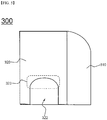
- a battery cell 300 is configured to have a structure in which an indented portion 322 of a second unit cell 320 has a shape different from the shape of the indented portion 122 of the second unit cell 120 shown in FIG. 1 . That is, the indented portion 122 of the second unit cell 120 shown in FIG. 1 has a planar rectangular shape, whereas a curved surface 323 is formed on the inside of the indented portion 322 of the second unit cell 320. That is, the indented portion 322 of the second unit cell 320 may be configured to have various structures, including a polygonal structure and an arc-shaped structure, in addition to the rectangular structure.
- a battery cell 400 is configured to have a structure in which a second unit cell 420 has a smaller width W and length L than a first unit cell 410.
- the battery cell 400 is configured to have a structure in which a step is formed in the width W and length L directions when viewed in vertical section.
- a battery cell 500 is configured to have a structure in which curved portions 512a and 512b are formed respectively at two corners of a first unit cell 510, which is different from the structure of the battery cell 100 shown in FIG. 1 , in which the curved portion 112 is formed at one corner of the first unit cell 110. That is, the position, number, and shape of the curved portions are not limited.
- battery cells according to various embodiments of the present invention may each be manufactured to have a structure in which an electrode assembly is mounted in a battery case, such as a hollow metal container, in a sealed state.
- each battery cell may be manufactured as a pouch-shaped battery cell configured to have a structure in which an electrode assembly is mounted in a battery case made of a laminate sheet including a resin layer and a metal layer in the state in which the outer edge of the battery case is sealed by thermal bonding.
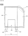
- FIGS. 8 and 9 are plan views showing battery cells according to other embodiments of the present invention.
- a battery cell 600 is configured to have a structure in which the battery cell 100 shown in FIG. 1 is manufactured as a pouch-shaped battery cell.
- the pouch-shaped battery cell 600 is configured to have a structure in which a stack, including a first unit cell 610 having a curved portion 612 and a second unit cell 620 having an indented portion 622, the second unit cell 620 being stacked on the first unit cell 610, is mounted in a receiving part having a shape corresponding to the outer surface of the stack in a sealed state.
- electrode terminals 632 and 634 are formed at opposite sides of the indented portion 622 of the second battery cell 620.
- the electrode terminals 632 and 634 protrude outward from the battery cell 600 such that the first unit cell 610 and the second unit cell 620 are connected to the outside in the state in which the first unit cell 610 and the second unit cell 620 are connected to each other in series or in parallel.
- the width W 1 of each of the opposite sides of the indented portion 622, at which the electrode terminals 632 and 634 are formed, is 5% to 30% of the width W 2 of the second unit cell 620.
- a battery cell 700 is configured to have a structure in which the battery cell 100 shown in FIG. 1 is manufactured as a pouch-shaped battery cell.
- the pouch-shaped battery cell 700 is configured to have a structure in which a stack, including a first unit cell 710 having a curved portion 712 and an indented portion 722 and a second unit cell 720 having an indented portion 722, the second unit cell 720 being stacked on the first unit cell 710, is mounted in a receiving part having a shape corresponding to the outer surface of the stack in a sealed state.
- electrode terminals 732 and 734 are formed at opposite sides of the indented portions 722.
- the electrode terminals 732 and 734 protrude outward from the battery cell 700 such that the first unit cell 710 and the second unit cell 720 are connected to the outside in the state in which the first unit cell 710 and the second unit cell 720 are connected to each other in series or in parallel.
- a battery cell according to the present invention is configured to have a structure including unit cells having an indented portion and an asymmetric structure. Consequently, it is possible to manufacture battery cells having various capacities and sizes based on this specific structure.
- the battery cell may be efficiently mounted in various spaces defined in the device, thereby maximizing the efficiency of space utilization in the device. Furthermore, it is possible to minimize thermal conduction and to improve heat dissipation efficiency based on the positions of electrode terminals in addition to the specific structure, thereby increasing the lifespan of the battery cell.
Landscapes
- Chemical & Material Sciences (AREA)
- Chemical Kinetics & Catalysis (AREA)
- Electrochemistry (AREA)
- General Chemical & Material Sciences (AREA)
- Engineering & Computer Science (AREA)
- Manufacturing & Machinery (AREA)
- Materials Engineering (AREA)
- Sealing Battery Cases Or Jackets (AREA)
- Secondary Cells (AREA)
- Battery Mounting, Suspending (AREA)
- Connection Of Batteries Or Terminals (AREA)
Claims (18)
- Batteriezelle, welche dazu eingerichtet ist, eine Struktur aufzuweisen, in welcher eine Elektrodenanordnung, umfassend eine positive Elektrode, eine negative Elektrode und einen zwischen der positiven Elektrode und der negativen Elektrode eingefügten Separator, in einem Batteriegehäuse montiert ist, wobei die Elektrodenanordnung zwei oder mehr Einheitszellen mit verschiedenen planaren Größen aufweist, wobei die Einheitszellen in einer Höhenrichtung an einer Basis einer Ebene gestapelt sind,
wenigstens eine Einheitszelle (a), welche aus den Einheitszellen ausgewählt ist, eine asymmetrische Struktur aufweist, welche an wenigstens einer Seite eines äußeren Rands davon an einer Basis einer Mittelachse gebildet ist, welche von oben betrachtet einen Hauptkörper der Einheitszelle (a) kreuzt, und wenigstens eine Einheitszelle (b), welche aus den Einheitszellen ausgewählt ist, einen vertieften Abschnitt aufweist, welcher von wenigstens einer Seite der Einheitszelle (b) in Richtung einer Mitte der Einheitszelle (b) vertieft ist, und wobei jede der Einheitszellen vorzugsweise eine Elektrodengruppe von einem gestapelten Typ oder einem gestapelten/gefalteten Typ oder einem Jelly-Roll-Typ ist, und die Batteriezelle vorzugsweise eine Lithium-Ionen-Batteriezelle oder eine Lithium-Ionen-Polymer-Batteriezelle ist. - Batteriezelle nach Anspruch 1, wobei die Elektrodenanordnung eine plattenförmige Elektrodenanordnung ist, welche dazu eingerichtet ist, eine Struktur aufzuweisen, in welcher Elektrodenanschlüsse an einer Seite der Elektrodenanordnung positioniert sind, oder an gegenüberliegenden Seiten der Elektrodenanordnung positioniert sind oder an einer Seite und einer benachbarten Seite der Elektrodenanordnung positioniert sind.
- Batteriezelle nach Anspruch 1, wobei die asymmetrische Struktur einen gekrümmten Abschnitt umfasst, in welchem der gekrümmte Abschnitt vorzugsweise an einer ausgewählt aus vier Seiten der Einheitszelle von oben betrachtet gebildet ist, oder über zwei oder mehr der vier Seiten der Einheitszelle von oben betrachtet gebildet ist.
- Batteriezelle nach Anspruch 3, wobei der gekrümmte Abschnitt dazu eingerichtet ist, eine Bogenform aufzuweisen, und ein konvexer Teil des Bogens einen Abschnitt einer Außenfläche der Einheitszelle (a) bildet.
- Batteriezelle nach Anspruch 4, wobei der gekrümmte Abschnitt dazu eingerichtet ist, eine Bogenform mit einem Radiusäquivalent von 10% bis 300% einer langen Seite der Einheitszelle (a) aufzuweisen.
- Batteriezelle nach Anspruch 4, wobei der gekrümmte Abschnitt dazu eingerichtet ist, eine Einzelbogenform mit einem einzelnen Radius und einem einzelnen Bogenzentrum aufzuweisen.
- Batteriezelle nach Anspruch 3, wobei der gekrümmte Abschnitt an einem Bereich der Einheitszelle gebildet ist, der mit keiner anderen an der Einheitszelle gestapelten Einheitszelle in einem Zustand, in dem sie zu der Einheitszelle benachbart ist, in Kontakt ist.
- Batteriezelle nach Anspruch 1, wobei der vertiefte Abschnitt dazu eingerichtet ist, von oben betrachtet eine Polygonform aufzuweisen, in welcher der vertiefte Abschnitt vorzugsweise dazu eingerichtet ist, von oben betrachtet eine rechteckige Form aufzuweisen.
- Batteriezelle nach Anspruch 1, wobei wenigstens eine Seite eines Inneren des vertieften Abschnitts dazu eingerichtet ist, von oben betrachtet eine Bogenform aufzuweisen.
- Batteriezelle nach Anspruch 1, wobei eine planare Breite des vertieften Abschnitts 5% bis 80% einer Breite der Einheitszelle (b) beträgt.
- Batteriezelle nach Anspruch 1, wobei die Elektrodenanordnung eine erste Einheitszelle und eine zweite Einheitszelle umfasst, wobei die erste Einheitszelle und die zweite Einheitszelle verschiedene planare Längen und/oder Breiten aufweisen.
- Batteriezelle nach Anspruch 11, wobei Elektrodenanschlüsse der ersten Einheitszelle und Elektrodenanschlüsse der zweiten Einheitszelle in dieselbe Richtung vorstehen.
- Batteriezelle nach Anspruch 12, wobei die Elektrodenanschlüsse der ersten Einheitszelle und die Elektrodenanschlüsse der zweiten Einheitszelle in einem Zustand miteinander elektrisch verbunden sind, in welchem die Elektrodenanschlüsse der ersten Einheitszelle und die Elektrodenanschlüsse der zweiten Einheitszelle vertikal gestapelt vorstehen.
- Batteriezelle nach Anspruch 12, wobei die Elektrodenanschlüsse an gegenüberliegenden Seiten eines vertieften Abschnitts gebildet sind, welcher an der ersten Einheitszelle und an Bereichen der zweiten Einheitszelle gebildet ist, welche den gegenüberliegenden Seiten des vertieften Abschnitts entsprechen, welcher an der ersten Einheitszelle gebildet ist, in welcher eine Breite von jeder der gegenüberliegenden Seiten des vertieften Abschnitts vorzugsweise 5% bis 30% einer Breite der ersten Einheitszelle beträgt.
- Batteriezelle nach Anspruch 11, wobei ein gekrümmter Abschnitt, welcher die asymmetrische Struktur bildet, von oben betrachtet an einer Seite der ersten Einheitszelle oder über zwei oder mehr Seiten der ersten Einheitszelle gebildet ist, und der vertiefte Abschnitt in einer Seite der zweiten Einheitszelle gebildet ist, in welcher die erste Einheitszelle und die zweite Einheitszelle vorzugsweise vertikal gestapelt sind, so dass wenigstens eine Seite der ersten Einheitszelle und wenigstens eine Seite der zweiten Einheitszelle zueinander benachbart sind.
- Batteriezelle nach Anspruch 15, wobei eine Breite der ersten Einheitszelle größer als eine Breite der zweiten Einheitszelle ist, in welcher ein Krümmungsradius des gekrümmten Abschnitts der ersten Einheitszelle vorzugsweise 50% bis 200% einer Differenz zwischen der Breite der ersten Einheitszelle und der Breite der zweiten Einheitszelle beträgt.
- Batteriezelle nach Anspruch 1, wobei eine Innenfläche des Batteriegehäuses derart gebildet ist, dass sie einer Außenfläche der Elektrodenanordnung entspricht, in welcher das Batteriegehäuse vorzugsweise aus einem Laminatblech, umfassend eine Metallschicht und eine Harzschicht, hergestellt ist.
- Vorrichtung, umfassend eine Batteriezelle nach einem der Ansprüche 1 bis 17 als Stromquelle, wobei die Vorrichtung vorzugsweise ausgewählt ist aus einer Gruppe, umfassend ein Mobiltelefon, einen tragbaren Computer, ein Smartphone, einen Tablet-PC, ein Smartpad, einen Netbook-Computer, ein leichtes Elektrofahrzeug (LEV), ein Elektrofahrzeug, ein Hybrid-Elektrofahrzeug, ein Plugin-Hybrid-Elektrofahrzeug und eine Energiespeichereinrichtung.
Applications Claiming Priority (2)
| Application Number | Priority Date | Filing Date | Title |
|---|---|---|---|
| KR20140031432 | 2014-03-18 | ||
| PCT/KR2014/010646 WO2015141920A1 (ko) | 2014-03-18 | 2014-11-07 | 비대칭 구조 및 만입 구조를 포함하는 전지셀 |
Publications (3)
| Publication Number | Publication Date |
|---|---|
| EP3107142A1 EP3107142A1 (de) | 2016-12-21 |
| EP3107142A4 EP3107142A4 (de) | 2017-03-22 |
| EP3107142B1 true EP3107142B1 (de) | 2017-09-13 |
Family
ID=54144851
Family Applications (1)
| Application Number | Title | Priority Date | Filing Date |
|---|---|---|---|
| EP14885986.1A Active EP3107142B1 (de) | 2014-03-18 | 2014-11-07 | Batteriezelle mit asymmetrischer und gekerbter struktur |
Country Status (6)
| Country | Link |
|---|---|
| US (1) | US10263226B2 (de) |
| EP (1) | EP3107142B1 (de) |
| JP (1) | JP6340431B2 (de) |
| KR (1) | KR101590979B1 (de) |
| CN (1) | CN106104900B (de) |
| WO (1) | WO2015141920A1 (de) |
Families Citing this family (15)
| Publication number | Priority date | Publication date | Assignee | Title |
|---|---|---|---|---|
| KR101950464B1 (ko) * | 2015-11-30 | 2019-02-20 | 주식회사 엘지화학 | 셀 케이스의 밀봉 신뢰성이 향상된 비정형 구조의 전지셀 |
| KR102082655B1 (ko) * | 2015-12-17 | 2020-02-28 | 주식회사 엘지화학 | 모서리가 절취되어 있는 구조의 전극조립체 제조방법 및 이를 사용하여 제조되는 전극조립체 |
| US9837682B1 (en) * | 2016-08-29 | 2017-12-05 | Microsoft Technology Licensing, Llc | Variable layer thickness in curved battery cell |
| JP6888634B2 (ja) * | 2016-12-06 | 2021-06-16 | 株式会社村田製作所 | 二次電池 |
| CN110050376B (zh) * | 2017-01-13 | 2022-07-22 | 株式会社村田制作所 | 二次电池 |
| CN110326147A (zh) * | 2017-02-22 | 2019-10-11 | 株式会社村田制作所 | 二次电池及其制造方法 |
| JP6737218B2 (ja) * | 2017-03-31 | 2020-08-05 | Tdk株式会社 | 非水電解液二次電池 |
| KR102244951B1 (ko) | 2017-11-21 | 2021-04-27 | 주식회사 엘지화학 | 전극 조립체와 이차전지 및 그 전극 조립체와 이차전지의 제조방법 |
| CN108965527A (zh) * | 2018-07-19 | 2018-12-07 | 深圳市金汇马科技有限公司 | 手机 |
| KR102552243B1 (ko) * | 2018-09-13 | 2023-07-07 | 주식회사 엘지에너지솔루션 | 이차전지 및 그 이차전지를 포함하는 전자기기 |
| WO2022103235A1 (ko) * | 2020-11-16 | 2022-05-19 | 삼성전자 주식회사 | 배터리를 포함하는 전자 장치 |
| WO2023221006A1 (zh) * | 2022-05-18 | 2023-11-23 | 北京小米移动软件有限公司 | 电芯、电池和终端设备 |
| CN116031499B (zh) * | 2023-02-28 | 2026-04-03 | 广东维都利新能源有限公司 | 一种瓣状叠片式电芯及其制备方法和包含该电芯的电池 |
| KR20240178893A (ko) * | 2023-06-23 | 2024-12-31 | 주식회사 엘지에너지솔루션 | 전극적층체 및 전극적층체를 포함하는 전지시스템 |
| KR20250001312A (ko) * | 2023-06-28 | 2025-01-06 | 주식회사 엘지에너지솔루션 | 전극적층체 및 전극적층체를 포함하는 전지시스템 |
Family Cites Families (11)
| Publication number | Priority date | Publication date | Assignee | Title |
|---|---|---|---|---|
| US6040078A (en) * | 1997-03-06 | 2000-03-21 | Mitsubishi Chemical Corporation | Free form battery apparatus |
| US6522525B1 (en) * | 2000-11-03 | 2003-02-18 | Cardiac Pacemakers, Inc. | Implantable heart monitors having flat capacitors with curved profiles |
| KR100440934B1 (ko) * | 2002-02-06 | 2004-07-21 | 삼성에스디아이 주식회사 | 이차전지 |
| DE602007013256D1 (de) * | 2006-08-21 | 2011-04-28 | Lg Chemical Ltd | Sekundärbatterie des beuteltyps mit verbesserter sicherheit und ausgezeichneter herstellungsprozesseigenschaft |
| JP5732687B2 (ja) * | 2010-03-19 | 2015-06-10 | エルジー ケム. エルティーディ. | ポーチ型ケース及びこれを含む電池パック |
| CN102544577A (zh) * | 2012-03-01 | 2012-07-04 | 宁德新能源科技有限公司 | 异形锂离子电池及其制造方法 |
| KR101403388B1 (ko) * | 2012-05-07 | 2014-06-03 | 주식회사 엘지화학 | 비정형 구조의 전지셀 및 이를 포함하는 전지모듈 |
| KR20130132231A (ko) * | 2012-05-25 | 2013-12-04 | 주식회사 엘지화학 | 단차를 갖는 전극 조립체 및 이를 포함하는 전지셀, 전지팩 및 디바이스 |
| KR20130133639A (ko) | 2012-05-29 | 2013-12-09 | 주식회사 엘지화학 | 전극 조립체, 전지셀, 전극 조립체의 제조방법 및 전지셀의 제조 방법 |
| KR20130133640A (ko) * | 2012-05-29 | 2013-12-09 | 주식회사 엘지화학 | 코너부 형상이 다양한 단차를 갖는 전극 조립체, 이를 포함하는 전지셀, 전지팩 및 디바이스 |
| KR20130135017A (ko) * | 2012-05-31 | 2013-12-10 | 주식회사 엘지화학 | 단차를 갖는 전극 조립체 및 이를 포함하는 전지셀, 전지팩 및 디바이스 |
-
2014
- 2014-11-06 KR KR1020140153648A patent/KR101590979B1/ko active Active
- 2014-11-07 EP EP14885986.1A patent/EP3107142B1/de active Active
- 2014-11-07 JP JP2016557124A patent/JP6340431B2/ja active Active
- 2014-11-07 CN CN201480077181.6A patent/CN106104900B/zh active Active
- 2014-11-07 WO PCT/KR2014/010646 patent/WO2015141920A1/ko not_active Ceased
- 2014-11-07 US US15/126,156 patent/US10263226B2/en active Active
Non-Patent Citations (1)
| Title |
|---|
| None * |
Also Published As
| Publication number | Publication date |
|---|---|
| CN106104900B (zh) | 2018-09-25 |
| EP3107142A1 (de) | 2016-12-21 |
| KR101590979B1 (ko) | 2016-02-03 |
| CN106104900A (zh) | 2016-11-09 |
| US10263226B2 (en) | 2019-04-16 |
| EP3107142A4 (de) | 2017-03-22 |
| JP6340431B2 (ja) | 2018-06-06 |
| KR20150108731A (ko) | 2015-09-30 |
| US20170092906A1 (en) | 2017-03-30 |
| WO2015141920A1 (ko) | 2015-09-24 |
| JP2017513183A (ja) | 2017-05-25 |
Similar Documents
| Publication | Publication Date | Title |
|---|---|---|
| US10263226B2 (en) | Battery cell having asymmetric and indented structure | |
| US12592419B2 (en) | Pouch type case and battery pack including the same | |
| US10629940B2 (en) | Battery cell including stepped structure | |
| EP2919312B1 (de) | Batteriezelle mit einer elektrodenanordnung mit wechselnder ausrichtungsstruktur | |
| US9425440B2 (en) | Compact battery cell having improved durability and battery pack comprising the same | |
| US9620789B2 (en) | Battery pack of the stair-like structure | |
| KR101402657B1 (ko) | 비정형 구조의 전지팩 | |
| EP3486967B1 (de) | Batteriezelle mit elektrodenleitungen, die der aussenfläche einer elektrodenanordnung zugewandt ist | |
| EP3264489A1 (de) | Sekundärbatterie | |
| US9935329B2 (en) | Stepped electrode group stack | |
| US10276887B2 (en) | Flexible battery cell | |
| KR20170030782A (ko) | 시트 구조의 전지케이스를 포함하는 파우치형 전지셀 | |
| KR20140110124A (ko) | 절취부를 포함하는 전극조립체 |
Legal Events
| Date | Code | Title | Description |
|---|---|---|---|
| STAA | Information on the status of an ep patent application or granted ep patent |
Free format text: STATUS: THE INTERNATIONAL PUBLICATION HAS BEEN MADE |
|
| PUAI | Public reference made under article 153(3) epc to a published international application that has entered the european phase |
Free format text: ORIGINAL CODE: 0009012 |
|
| STAA | Information on the status of an ep patent application or granted ep patent |
Free format text: STATUS: REQUEST FOR EXAMINATION WAS MADE |
|
| 17P | Request for examination filed |
Effective date: 20160914 |
|
| AK | Designated contracting states |
Kind code of ref document: A1 Designated state(s): AL AT BE BG CH CY CZ DE DK EE ES FI FR GB GR HR HU IE IS IT LI LT LU LV MC MK MT NL NO PL PT RO RS SE SI SK SM TR |
|
| AX | Request for extension of the european patent |
Extension state: BA ME |
|
| A4 | Supplementary search report drawn up and despatched |
Effective date: 20170220 |
|
| RIC1 | Information provided on ipc code assigned before grant |
Ipc: H01M 10/04 20060101ALI20170214BHEP Ipc: H01M 2/10 20060101ALI20170214BHEP Ipc: H01M 10/058 20100101AFI20170214BHEP |
|
| GRAP | Despatch of communication of intention to grant a patent |
Free format text: ORIGINAL CODE: EPIDOSNIGR1 |
|
| STAA | Information on the status of an ep patent application or granted ep patent |
Free format text: STATUS: GRANT OF PATENT IS INTENDED |
|
| RIC1 | Information provided on ipc code assigned before grant |
Ipc: H01M 2/10 20060101ALI20170426BHEP Ipc: H01M 2/06 20060101ALI20170426BHEP Ipc: H01M 10/04 20060101ALI20170426BHEP Ipc: H01M 10/058 20100101AFI20170426BHEP Ipc: H01M 2/30 20060101ALI20170426BHEP |
|
| DAX | Request for extension of the european patent (deleted) | ||
| INTG | Intention to grant announced |
Effective date: 20170526 |
|
| GRAS | Grant fee paid |
Free format text: ORIGINAL CODE: EPIDOSNIGR3 |
|
| GRAA | (expected) grant |
Free format text: ORIGINAL CODE: 0009210 |
|
| STAA | Information on the status of an ep patent application or granted ep patent |
Free format text: STATUS: THE PATENT HAS BEEN GRANTED |
|
| AK | Designated contracting states |
Kind code of ref document: B1 Designated state(s): AL AT BE BG CH CY CZ DE DK EE ES FI FR GB GR HR HU IE IS IT LI LT LU LV MC MK MT NL NO PL PT RO RS SE SI SK SM TR |
|
| REG | Reference to a national code |
Ref country code: GB Ref legal event code: FG4D |
|
| REG | Reference to a national code |
Ref country code: CH Ref legal event code: EP |
|
| REG | Reference to a national code |
Ref country code: IE Ref legal event code: FG4D |
|
| REG | Reference to a national code |
Ref country code: AT Ref legal event code: REF Ref document number: 928973 Country of ref document: AT Kind code of ref document: T Effective date: 20171015 |
|
| REG | Reference to a national code |
Ref country code: FR Ref legal event code: PLFP Year of fee payment: 4 |
|
| REG | Reference to a national code |
Ref country code: DE Ref legal event code: R096 Ref document number: 602014014708 Country of ref document: DE |
|
| REG | Reference to a national code |
Ref country code: NL Ref legal event code: MP Effective date: 20170913 |
|
| REG | Reference to a national code |
Ref country code: LT Ref legal event code: MG4D |
|
| PG25 | Lapsed in a contracting state [announced via postgrant information from national office to epo] |
Ref country code: HR Free format text: LAPSE BECAUSE OF FAILURE TO SUBMIT A TRANSLATION OF THE DESCRIPTION OR TO PAY THE FEE WITHIN THE PRESCRIBED TIME-LIMIT Effective date: 20170913 Ref country code: FI Free format text: LAPSE BECAUSE OF FAILURE TO SUBMIT A TRANSLATION OF THE DESCRIPTION OR TO PAY THE FEE WITHIN THE PRESCRIBED TIME-LIMIT Effective date: 20170913 Ref country code: LT Free format text: LAPSE BECAUSE OF FAILURE TO SUBMIT A TRANSLATION OF THE DESCRIPTION OR TO PAY THE FEE WITHIN THE PRESCRIBED TIME-LIMIT Effective date: 20170913 Ref country code: SE Free format text: LAPSE BECAUSE OF FAILURE TO SUBMIT A TRANSLATION OF THE DESCRIPTION OR TO PAY THE FEE WITHIN THE PRESCRIBED TIME-LIMIT Effective date: 20170913 Ref country code: NO Free format text: LAPSE BECAUSE OF FAILURE TO SUBMIT A TRANSLATION OF THE DESCRIPTION OR TO PAY THE FEE WITHIN THE PRESCRIBED TIME-LIMIT Effective date: 20171213 |
|
| REG | Reference to a national code |
Ref country code: AT Ref legal event code: MK05 Ref document number: 928973 Country of ref document: AT Kind code of ref document: T Effective date: 20170913 |
|
| PG25 | Lapsed in a contracting state [announced via postgrant information from national office to epo] |
Ref country code: RS Free format text: LAPSE BECAUSE OF FAILURE TO SUBMIT A TRANSLATION OF THE DESCRIPTION OR TO PAY THE FEE WITHIN THE PRESCRIBED TIME-LIMIT Effective date: 20170913 Ref country code: ES Free format text: LAPSE BECAUSE OF FAILURE TO SUBMIT A TRANSLATION OF THE DESCRIPTION OR TO PAY THE FEE WITHIN THE PRESCRIBED TIME-LIMIT Effective date: 20170913 Ref country code: LV Free format text: LAPSE BECAUSE OF FAILURE TO SUBMIT A TRANSLATION OF THE DESCRIPTION OR TO PAY THE FEE WITHIN THE PRESCRIBED TIME-LIMIT Effective date: 20170913 Ref country code: GR Free format text: LAPSE BECAUSE OF FAILURE TO SUBMIT A TRANSLATION OF THE DESCRIPTION OR TO PAY THE FEE WITHIN THE PRESCRIBED TIME-LIMIT Effective date: 20171214 Ref country code: BG Free format text: LAPSE BECAUSE OF FAILURE TO SUBMIT A TRANSLATION OF THE DESCRIPTION OR TO PAY THE FEE WITHIN THE PRESCRIBED TIME-LIMIT Effective date: 20171213 |
|
| PG25 | Lapsed in a contracting state [announced via postgrant information from national office to epo] |
Ref country code: NL Free format text: LAPSE BECAUSE OF FAILURE TO SUBMIT A TRANSLATION OF THE DESCRIPTION OR TO PAY THE FEE WITHIN THE PRESCRIBED TIME-LIMIT Effective date: 20170913 |
|
| PG25 | Lapsed in a contracting state [announced via postgrant information from national office to epo] |
Ref country code: CZ Free format text: LAPSE BECAUSE OF FAILURE TO SUBMIT A TRANSLATION OF THE DESCRIPTION OR TO PAY THE FEE WITHIN THE PRESCRIBED TIME-LIMIT Effective date: 20170913 Ref country code: PL Free format text: LAPSE BECAUSE OF FAILURE TO SUBMIT A TRANSLATION OF THE DESCRIPTION OR TO PAY THE FEE WITHIN THE PRESCRIBED TIME-LIMIT Effective date: 20170913 |
|
| PG25 | Lapsed in a contracting state [announced via postgrant information from national office to epo] |
Ref country code: EE Free format text: LAPSE BECAUSE OF FAILURE TO SUBMIT A TRANSLATION OF THE DESCRIPTION OR TO PAY THE FEE WITHIN THE PRESCRIBED TIME-LIMIT Effective date: 20170913 Ref country code: IT Free format text: LAPSE BECAUSE OF FAILURE TO SUBMIT A TRANSLATION OF THE DESCRIPTION OR TO PAY THE FEE WITHIN THE PRESCRIBED TIME-LIMIT Effective date: 20170913 Ref country code: SK Free format text: LAPSE BECAUSE OF FAILURE TO SUBMIT A TRANSLATION OF THE DESCRIPTION OR TO PAY THE FEE WITHIN THE PRESCRIBED TIME-LIMIT Effective date: 20170913 Ref country code: AT Free format text: LAPSE BECAUSE OF FAILURE TO SUBMIT A TRANSLATION OF THE DESCRIPTION OR TO PAY THE FEE WITHIN THE PRESCRIBED TIME-LIMIT Effective date: 20170913 Ref country code: SM Free format text: LAPSE BECAUSE OF FAILURE TO SUBMIT A TRANSLATION OF THE DESCRIPTION OR TO PAY THE FEE WITHIN THE PRESCRIBED TIME-LIMIT Effective date: 20170913 Ref country code: IS Free format text: LAPSE BECAUSE OF FAILURE TO SUBMIT A TRANSLATION OF THE DESCRIPTION OR TO PAY THE FEE WITHIN THE PRESCRIBED TIME-LIMIT Effective date: 20180113 |
|
| REG | Reference to a national code |
Ref country code: DE Ref legal event code: R097 Ref document number: 602014014708 Country of ref document: DE |
|
| PG25 | Lapsed in a contracting state [announced via postgrant information from national office to epo] |
Ref country code: MC Free format text: LAPSE BECAUSE OF FAILURE TO SUBMIT A TRANSLATION OF THE DESCRIPTION OR TO PAY THE FEE WITHIN THE PRESCRIBED TIME-LIMIT Effective date: 20170913 |
|
| PLBE | No opposition filed within time limit |
Free format text: ORIGINAL CODE: 0009261 |
|
| STAA | Information on the status of an ep patent application or granted ep patent |
Free format text: STATUS: NO OPPOSITION FILED WITHIN TIME LIMIT |
|
| PG25 | Lapsed in a contracting state [announced via postgrant information from national office to epo] |
Ref country code: CH Free format text: LAPSE BECAUSE OF NON-PAYMENT OF DUE FEES Effective date: 20171130 Ref country code: DK Free format text: LAPSE BECAUSE OF FAILURE TO SUBMIT A TRANSLATION OF THE DESCRIPTION OR TO PAY THE FEE WITHIN THE PRESCRIBED TIME-LIMIT Effective date: 20170913 Ref country code: LI Free format text: LAPSE BECAUSE OF NON-PAYMENT OF DUE FEES Effective date: 20171130 |
|
| 26N | No opposition filed |
Effective date: 20180614 |
|
| PG25 | Lapsed in a contracting state [announced via postgrant information from national office to epo] |
Ref country code: LU Free format text: LAPSE BECAUSE OF NON-PAYMENT OF DUE FEES Effective date: 20171107 |
|
| REG | Reference to a national code |
Ref country code: BE Ref legal event code: MM Effective date: 20171130 |
|
| REG | Reference to a national code |
Ref country code: IE Ref legal event code: MM4A |
|
| PG25 | Lapsed in a contracting state [announced via postgrant information from national office to epo] |
Ref country code: MT Free format text: LAPSE BECAUSE OF NON-PAYMENT OF DUE FEES Effective date: 20171107 |
|
| REG | Reference to a national code |
Ref country code: FR Ref legal event code: PLFP Year of fee payment: 5 |
|
| PG25 | Lapsed in a contracting state [announced via postgrant information from national office to epo] |
Ref country code: IE Free format text: LAPSE BECAUSE OF NON-PAYMENT OF DUE FEES Effective date: 20171107 |
|
| PG25 | Lapsed in a contracting state [announced via postgrant information from national office to epo] |
Ref country code: SI Free format text: LAPSE BECAUSE OF FAILURE TO SUBMIT A TRANSLATION OF THE DESCRIPTION OR TO PAY THE FEE WITHIN THE PRESCRIBED TIME-LIMIT Effective date: 20170913 Ref country code: BE Free format text: LAPSE BECAUSE OF NON-PAYMENT OF DUE FEES Effective date: 20171130 |
|
| PG25 | Lapsed in a contracting state [announced via postgrant information from national office to epo] |
Ref country code: HU Free format text: LAPSE BECAUSE OF FAILURE TO SUBMIT A TRANSLATION OF THE DESCRIPTION OR TO PAY THE FEE WITHIN THE PRESCRIBED TIME-LIMIT; INVALID AB INITIO Effective date: 20141107 |
|
| PG25 | Lapsed in a contracting state [announced via postgrant information from national office to epo] |
Ref country code: RO Free format text: LAPSE BECAUSE OF FAILURE TO SUBMIT A TRANSLATION OF THE DESCRIPTION OR TO PAY THE FEE WITHIN THE PRESCRIBED TIME-LIMIT Effective date: 20170913 |
|
| PG25 | Lapsed in a contracting state [announced via postgrant information from national office to epo] |
Ref country code: CY Free format text: LAPSE BECAUSE OF FAILURE TO SUBMIT A TRANSLATION OF THE DESCRIPTION OR TO PAY THE FEE WITHIN THE PRESCRIBED TIME-LIMIT Effective date: 20170913 |
|
| PG25 | Lapsed in a contracting state [announced via postgrant information from national office to epo] |
Ref country code: MK Free format text: LAPSE BECAUSE OF FAILURE TO SUBMIT A TRANSLATION OF THE DESCRIPTION OR TO PAY THE FEE WITHIN THE PRESCRIBED TIME-LIMIT Effective date: 20170913 |
|
| PG25 | Lapsed in a contracting state [announced via postgrant information from national office to epo] |
Ref country code: TR Free format text: LAPSE BECAUSE OF FAILURE TO SUBMIT A TRANSLATION OF THE DESCRIPTION OR TO PAY THE FEE WITHIN THE PRESCRIBED TIME-LIMIT Effective date: 20170913 |
|
| PG25 | Lapsed in a contracting state [announced via postgrant information from national office to epo] |
Ref country code: PT Free format text: LAPSE BECAUSE OF FAILURE TO SUBMIT A TRANSLATION OF THE DESCRIPTION OR TO PAY THE FEE WITHIN THE PRESCRIBED TIME-LIMIT Effective date: 20170913 |
|
| PG25 | Lapsed in a contracting state [announced via postgrant information from national office to epo] |
Ref country code: AL Free format text: LAPSE BECAUSE OF FAILURE TO SUBMIT A TRANSLATION OF THE DESCRIPTION OR TO PAY THE FEE WITHIN THE PRESCRIBED TIME-LIMIT Effective date: 20170913 |
|
| REG | Reference to a national code |
Ref country code: DE Ref legal event code: R081 Ref document number: 602014014708 Country of ref document: DE Owner name: LG ENERGY SOLUTION LTD., KR Free format text: FORMER OWNER: LG CHEM. LTD., SEOUL, KR Ref country code: DE Ref legal event code: R081 Ref document number: 602014014708 Country of ref document: DE Owner name: LG ENERGY SOLUTION, LTD., KR Free format text: FORMER OWNER: LG CHEM. LTD., SEOUL, KR |
|
| P01 | Opt-out of the competence of the unified patent court (upc) registered |
Effective date: 20230512 |
|
| REG | Reference to a national code |
Ref country code: GB Ref legal event code: 732E Free format text: REGISTERED BETWEEN 20230824 AND 20230831 |
|
| REG | Reference to a national code |
Ref country code: DE Ref legal event code: R081 Ref document number: 602014014708 Country of ref document: DE Owner name: LG ENERGY SOLUTION, LTD., KR Free format text: FORMER OWNER: LG ENERGY SOLUTION LTD., SEOUL, KR |
|
| PGFP | Annual fee paid to national office [announced via postgrant information from national office to epo] |
Ref country code: DE Payment date: 20251020 Year of fee payment: 12 |
|
| PGFP | Annual fee paid to national office [announced via postgrant information from national office to epo] |
Ref country code: GB Payment date: 20251023 Year of fee payment: 12 |
|
| PGFP | Annual fee paid to national office [announced via postgrant information from national office to epo] |
Ref country code: FR Payment date: 20251021 Year of fee payment: 12 |