EP3107039B1 - Verfahren und vorrichtung zur verfolgung von zielen - Google Patents
Verfahren und vorrichtung zur verfolgung von zielen Download PDFInfo
- Publication number
- EP3107039B1 EP3107039B1 EP16175214.2A EP16175214A EP3107039B1 EP 3107039 B1 EP3107039 B1 EP 3107039B1 EP 16175214 A EP16175214 A EP 16175214A EP 3107039 B1 EP3107039 B1 EP 3107039B1
- Authority
- EP
- European Patent Office
- Prior art keywords
- candidate
- image
- sub
- chip
- scores
- Prior art date
- Legal status (The legal status is an assumption and is not a legal conclusion. Google has not performed a legal analysis and makes no representation as to the accuracy of the status listed.)
- Active
Links
Images


Classifications
-
- G—PHYSICS
- G06—COMPUTING OR CALCULATING; COUNTING
- G06T—IMAGE DATA PROCESSING OR GENERATION, IN GENERAL
- G06T7/00—Image analysis
- G06T7/20—Analysis of motion
- G06T7/246—Analysis of motion using feature-based methods, e.g. the tracking of corners or segments
- G06T7/248—Analysis of motion using feature-based methods, e.g. the tracking of corners or segments involving reference images or patches
-
- G—PHYSICS
- G06—COMPUTING OR CALCULATING; COUNTING
- G06F—ELECTRIC DIGITAL DATA PROCESSING
- G06F18/00—Pattern recognition
- G06F18/20—Analysing
- G06F18/22—Matching criteria, e.g. proximity measures
-
- G—PHYSICS
- G06—COMPUTING OR CALCULATING; COUNTING
- G06F—ELECTRIC DIGITAL DATA PROCESSING
- G06F18/00—Pattern recognition
- G06F18/20—Analysing
- G06F18/25—Fusion techniques
- G06F18/254—Fusion techniques of classification results, e.g. of results related to same input data
-
- G—PHYSICS
- G06—COMPUTING OR CALCULATING; COUNTING
- G06F—ELECTRIC DIGITAL DATA PROCESSING
- G06F18/00—Pattern recognition
- G06F18/20—Analysing
- G06F18/25—Fusion techniques
- G06F18/254—Fusion techniques of classification results, e.g. of results related to same input data
- G06F18/256—Fusion techniques of classification results, e.g. of results related to same input data of results relating to different input data, e.g. multimodal recognition
-
- G—PHYSICS
- G06—COMPUTING OR CALCULATING; COUNTING
- G06V—IMAGE OR VIDEO RECOGNITION OR UNDERSTANDING
- G06V10/00—Arrangements for image or video recognition or understanding
- G06V10/10—Image acquisition
- G06V10/12—Details of acquisition arrangements; Constructional details thereof
- G06V10/14—Optical characteristics of the device performing the acquisition or on the illumination arrangements
- G06V10/143—Sensing or illuminating at different wavelengths
-
- G—PHYSICS
- G06—COMPUTING OR CALCULATING; COUNTING
- G06V—IMAGE OR VIDEO RECOGNITION OR UNDERSTANDING
- G06V10/00—Arrangements for image or video recognition or understanding
- G06V10/70—Arrangements for image or video recognition or understanding using pattern recognition or machine learning
- G06V10/77—Processing image or video features in feature spaces; using data integration or data reduction, e.g. principal component analysis [PCA] or independent component analysis [ICA] or self-organising maps [SOM]; Blind source separation
- G06V10/80—Fusion, i.e. combining data from various sources at the sensor level, preprocessing level, feature extraction level or classification level
- G06V10/809—Fusion, i.e. combining data from various sources at the sensor level, preprocessing level, feature extraction level or classification level of classification results, e.g. where the classifiers operate on the same input data
- G06V10/811—Fusion, i.e. combining data from various sources at the sensor level, preprocessing level, feature extraction level or classification level of classification results, e.g. where the classifiers operate on the same input data the classifiers operating on different input data, e.g. multi-modal recognition
-
- G—PHYSICS
- G06—COMPUTING OR CALCULATING; COUNTING
- G06V—IMAGE OR VIDEO RECOGNITION OR UNDERSTANDING
- G06V20/00—Scenes; Scene-specific elements
- G06V20/50—Context or environment of the image
- G06V20/52—Surveillance or monitoring of activities, e.g. for recognising suspicious objects
-
- G—PHYSICS
- G06—COMPUTING OR CALCULATING; COUNTING
- G06V—IMAGE OR VIDEO RECOGNITION OR UNDERSTANDING
- G06V20/00—Scenes; Scene-specific elements
- G06V20/50—Context or environment of the image
- G06V20/52—Surveillance or monitoring of activities, e.g. for recognising suspicious objects
- G06V20/54—Surveillance or monitoring of activities, e.g. for recognising suspicious objects of traffic, e.g. cars on the road, trains or boats
-
- G—PHYSICS
- G06—COMPUTING OR CALCULATING; COUNTING
- G06T—IMAGE DATA PROCESSING OR GENERATION, IN GENERAL
- G06T2207/00—Indexing scheme for image analysis or image enhancement
- G06T2207/10—Image acquisition modality
- G06T2207/10048—Infrared image
-
- G—PHYSICS
- G06—COMPUTING OR CALCULATING; COUNTING
- G06T—IMAGE DATA PROCESSING OR GENERATION, IN GENERAL
- G06T2207/00—Indexing scheme for image analysis or image enhancement
- G06T2207/20—Special algorithmic details
- G06T2207/20021—Dividing image into blocks, subimages or windows
-
- G—PHYSICS
- G06—COMPUTING OR CALCULATING; COUNTING
- G06V—IMAGE OR VIDEO RECOGNITION OR UNDERSTANDING
- G06V10/00—Arrangements for image or video recognition or understanding
- G06V10/70—Arrangements for image or video recognition or understanding using pattern recognition or machine learning
- G06V10/74—Image or video pattern matching; Proximity measures in feature spaces
- G06V10/75—Organisation of the matching processes, e.g. simultaneous or sequential comparisons of image or video features; Coarse-fine approaches, e.g. multi-scale approaches; using context analysis; Selection of dictionaries
- G06V10/759—Region-based matching
-
- G—PHYSICS
- G06—COMPUTING OR CALCULATING; COUNTING
- G06V—IMAGE OR VIDEO RECOGNITION OR UNDERSTANDING
- G06V20/00—Scenes; Scene-specific elements
- G06V20/10—Terrestrial scenes
- G06V20/194—Terrestrial scenes using hyperspectral data, i.e. more or other wavelengths than RGB
Definitions
- the present disclosure relates generally to processing images and, in particular, to processing images to track targets of interest. Still more particularly, the present disclosure relates to a method and apparatus for tracking a target of interest using a sequence of electro-optical images and a sequence of infrared images that have been synchronized with respect to time.
- Sensor devices are oftentimes used to generate sensor data for the purpose of tracking targets of interest.
- Target tracking may be performed in a number of different ways.
- an unmanned aerial vehicle UAV
- UAV unmanned aerial vehicle
- the target of interest may be, for example, but is not limited to, a ground vehicle.
- Electro-optical (EO) sensors, infrared sensors (IR), and sometimes a combination of both are used to perform target tracking. Electro-optical sensors are most often used for performing daytime surveillance. Infrared sensors are used for performing both daytime and nighttime surveillance. Processing only data received from electro-optical sensors or only data received from infrared sensors may limit target tracking capabilities. For example, this type of data processing may not provide a desired level of accuracy and efficacy with respect to target tracking.
- Some currently available methods for target tracking include processing data from both electro-optical sensors and infrared sensors together. While these methods may be more effective than processing data received from one type of sensor, these methods may be unable to track targets that are at least partially occluded in images with the desired level of accuracy and efficacy. Therefore, it would be desirable to have a method and apparatus that take into account at least some of the issues discussed above, as well as other possible issues.
- Cited document EP 2 575 079 A2 discloses, according to its abstract, a method and apparatus for processing images.
- a sequence of images for a scene is received from an imaging system.
- An object in the scene is detected using the sequence of images.
- a viewpoint of the imaging system is registered to a model of the scene using a region in the model of the scene in which an expected behavior of the object is expected to occur.
- Cited document WO 2008/057451 A2 discloses, according to its abstract, an automated method for classifying an object in a sequence of video frames.
- the object is tracked in multiple frames of the sequence of video frame, and feature descriptors are determined for the object for each of the multiple frames.
- Multiple classification scores are computed by matching said feature descriptors for the object for each of the multiple frames with feature descriptors for a candidate class in a classification database. Said multiple classification scores are aggregated to generate an estimated probability that the object is a member of the candidate class.
- a computer-implemented method for processing images to track a target of interest is provided as defined in claim 1. Variants of this method are defined in dependent claims 2-4.
- an apparatus for tracking a target of interest is provided as defined in claim 5. Variants of that apparatus are defined in dependent claims 6-8.
- the illustrative embodiments recognize and take into account different considerations. For example, the illustrative embodiments recognize and take into account that it may be desirable to provide a method for tracking targets of interest that uses both electro-optical images and infrared images. In particular, the illustrative embodiments recognize and take into account that it may be desirable to provide a method for tracking targets of interest that uses a first type of image to match a candidate target to a target of interest based on chromaticity and a second type of image to determine, with a desired level of accuracy, whether the candidate target is indeed the target of interest based on shape information.
- the illustrative embodiments provide a method for processing images to perform target tracking.
- a set of candidate targets is identified in a first image and in a second image that corresponds with the first image.
- a set of first scores is generated for the set of candidate targets using the first image.
- a set of second scores is generated for the set of candidate targets using the second image.
- a set of final scores is computed for the set of candidate targets using the set of first scores and the set of second scores.
- a determination is made as to which of the set of candidate targets is a target of interest based on the set of final scores.
- the first image and the second image take the form of an electro-optical image and an infrared image. Chromaticity and shape information is identified for each candidate target in these two images. Chromaticity information is identified using the electro-optical image, while shape information is identified using the infrared image. The chromaticity information is used to generate a first score for each candidate target, while the shape information is used to generate a second score for each candidate target. A final score based on both the first score and the second score is identified for each candidate target. The final score is used to determine whether that candidate target is the target of interest.
- Using both the electro-optical image and the infrared image in this manner may provide an effective and accurate method for tracking targets of interest. Further, this type of processing may be "occlusion-robust" in that targets may be tracked even when partially occluded in images.
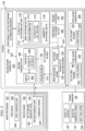
- image processing system 100 may be implemented using software, hardware, firmware, or a combination thereof.
- the hardware may include one or more circuits that operate to perform the operations performed by image processing system 100.
- the hardware may take the form of a circuit system, an integrated circuit, an application specific integrated circuit (ASIC), a programmable logic device, or some other suitable type of hardware device configured to perform any number of operations.
- ASIC application specific integrated circuit
- a programmable logic device may be configured to perform certain operations.
- the device may be permanently configured to perform these operations or may be reconfigurable.
- a programmable logic device may take the form of, for example, without limitation, a programmable logic array, a programmable array logic, a field programmable logic array, a field programmable gate array, or some other type of programmable hardware device.
- image processing system 100 may be implemented in computer system 102.
- Image processing system 100 may be used to process sequence of first images 104 and sequence of second images 106.
- Each of these two sequences of images may be a plurality of images ordered with respect to time.
- Each image in each sequence of images may be a still image.
- sequence of first images 104 may be referred to as a first video
- second sequence of second images 106 may be referred to as a second video.
- each image in the first video and the second video may be referred to as a frame.
- Image processing system 100 may receive sequence of first images 104 from first imaging system 108.
- Image processing system 100 may receive sequence of second images 106 from second imaging system 110.
- first imaging system 108 and second imaging system 110 take the form of electro-optical (EO) imaging system 112 and infrared (IR) imaging system 114, respectively.
- EO electro-optical
- IR infrared
- first imaging system 108 takes the form of electro-optical imaging system 112
- sequence of first images 104 may be referred to as sequence of electro-optical images 116.
- second imaging system 110 takes the form of infrared imaging system 114
- sequence of second images 106 may be referred to as sequence of infrared images 118.
- Image processing system 100 may process sequence of first images 104 and sequence of second images 106 to track target of interest 120.
- Target of interest 120 may be, for example, without limitation, a moving target of interest.
- target of interest 120 may be identified prior to the beginning of processing sequence of first images 104 and sequence of second images 106.
- target of interest 120 may be acquired during processing of sequence of first images 104 and sequence of second images 106.
- Target of interest 120 may take a number of different forms.
- target of interest 120 may be a person, a type of ground vehicle, a type of aerial vehicle, a water vehicle, or some other type of object.
- the ground vehicle may be, for example, without limitation, a car, a truck, a tank, or some other type of ground vehicle.
- the aerial vehicle may be a missile, an aircraft, an unmanned aerial vehicle, or some other type of aerial vehicle.
- image processing system 100 includes image processor 122, scorer 124, and target manager 126.
- image processor 122, scorer 124, and target manager 126 may be implemented using hardware, firmware, software, or a combination thereof.
- image processor 122 synchronizes sequence of first images 104 and sequence of second images 106. Synchronizing these two sequences may include associating the images in these sequences based on time.
- image processor 122 may identify synchronized image pair 125.
- Synchronized image pair 125 may include first image 128 from sequence of first images 104 and second image 130 from sequence of second images 106 that correspond to each other based on the points in time at which these two images were generated.
- first image 128 and second image 130 may correspond to a substantially same point in time.
- First image 128 and second image 130 take the form of electro-optical image 132 and infrared image 134, respectively.
- synchronized image pair 125 may also be aligned with respect to reference coordinate system 127.
- first image 128 and second image 130 may be aligned such that the scene captured in first image 128 is substantially aligned with the scene captured in second image 130 with respect to reference coordinate system 127.
- image processor 122 may process both first image 128 and second image 130 to identify set of candidate targets 136.
- Each candidate target in set of candidate targets 136 may potentially be target of interest 120.
- first image 128 and second image 130 may be fused together to form a combined image from which set of candidate targets 136 may be identified.
- a chip may be a region of an image.
- a candidate chip such as one of set of first candidate chips 138 or one of set of second candidate chips 140, may be a region of an image that captures a candidate target.
- a candidate chip may be a region of an image that has been identified as potentially capturing target of interest 120.
- set of first candidate chips 138 and set of second candidate chips 140 may include the same number of candidate chips.
- each first candidate chip of set of first candidate chips 138 may share a one-to-one correspondence with a corresponding second candidate chip of set of second candidate chips 140.
- First reference chip 148 and second reference chip 150 may be stored in database 151.
- first reference chip 148 and second reference chip 150 may belong to plurality of reference chips 152 stored in database 151.
- image processor 122 may include moving target detector 200.
- Moving target detector 200 may be implemented using hardware, firmware, software, or a combination thereof.
- Candidate target 202 may be, for example, without limitation, a moving object.
- Moving target detector 200 may use any number of algorithms, techniques, or computational processors to detect candidate target 202.
- first score generator 208 may begin by dividing first candidate chip 204 into grid of cells 210.
- Grid of cells 210 may be a grid of multiple rows and multiple columns.
- First score generator 208 may then use number of sub-region masks 212 to identify plurality of sub-regions 214.
- a "number of' items may include one or more items.
- number of sub-region masks 212 may include one or more masks.
- plurality of sub-regions 214 is identified by moving each of number of sub-region masks 212 to different locations over first candidate chip 204.
- plurality of sub-regions 214 may include sub-regions that have different sizes and that overlap. Using sub-regions that have different sizes and that overlap may enable tracking target of interest 120 even when target of interest 120 is partially occluded within first image 128.
- First score generator 208 generates plurality of signatures 218 for plurality of sub-regions 214.
- each signature of plurality of signatures 218 is generated for a corresponding sub-region of plurality of sub-regions 214.
- Sub-region 220 may be an example of one of plurality of sub-regions 214.
- Sub-region 220 may include plurality of cells 222, which may include only a portion and not all of the cells in grid of cells 210.
- first score generator 208 identifies signature 224 for sub-region 220.
- Signature 224 may include chromaticity information 225.
- Chromaticity information 225 may be generated based on the pixel values of the pixels that fall within sub-region 220.
- First score generator 208 then identifies plurality of reference sub-regions 226 in first reference chip 148. For example, without limitation, number of sub-region masks 212 may also be used to identify plurality of reference sub-regions 226. First score generator 208 pairs each of plurality of reference sub-regions 226 with each sub-region of plurality of sub-regions 214 to form plurality of pairs 228. In this manner, each of plurality of pairs 228 includes a unique combination of a sub-region from plurality of sub-regions 214 and a reference sub-region from plurality of reference sub-regions 226.
- Plurality of initial scores 230 are then generated for plurality of pairs 228.
- first score generator 208 generates an initial score for each of plurality of pairs 228 to form plurality of initial scores 230.
- an initial score in plurality of initial scores 230 for a corresponding pair in plurality of pairs 228 indicates a measure of the likeness between the sub-region and the reference sub-region in that pair.
- the initial score is a measure of the degree of matching between the sub-region and the reference sub-region in that pair, with respect to at least chromaticity.
- plurality of initial scores 230 may be generated based on Kullback-Leibler divergence 240.
- best matched pair 234 includes best matched sub-region 236 and best matched referenced sub-region 238.
- Best initial score 232 is then assigned as first score 206 for first candidate chip 204, and thereby, first score 206 for candidate target 202.
- image processor 122 may process second image 130 to generate set of second candidate chips 140.
- image processor 122 identifies second candidate chip 300 in second image 130 that corresponds to first candidate chip 204 in first image 128 from Figure 2 .
- image processor 122 may identify second candidate chip 300 in second image 130 based on the alignment of second image 130 with first image 128 with respect to reference coordinate system 127 in Figure 1 .
- Second candidate chip 300 may have the same size as and be in the same location as first candidate chip 204 with respect to reference coordinate system 127 in Figure 1 .
- Scorer 124 may include second score generator 302.
- Second score generator 302 may process second candidate chip 300.
- second score generator 302 may divide second candidate chip 300 into grid of cells 304.
- grid of cells 304 may have the same dimensions as grid of cells 210 for first candidate chip 204 in Figure 2 .
- Second score generator 302 identifies sub-region 306 comprising plurality of cells 308 within second candidate chip 300. Sub-region 306 is identified based on best matched subregion 236 identified for first candidate chip 204 in Figure 2 .
- sub-region 306 may be the entire second candidate chip 300.
- second candidate chip 300 may be identified as having the same size and location in second image 130 as best matched sub-region 236 in Figure 2 with respect to reference coordinate system 127.
- Second candidate chip 300 may then be divided into grid of cells 304, which may in its entirety form sub-region 306 comprised of plurality of cells 308.
- Second score generator 302 may then generate second score 310 for sub-region 306, which may become second score 310 for second candidate chip 300 and, thereby, candidate target 202.
- second score generator 302 identifies base histogram vector 312 for sub-region 306.
- Base histogram vector 312 may be computed using the method of computing histograms of oriented gradients (HoG).
- Base histogram vector 312 is a feature descriptor. This feature descriptor is generated by computing a histogram of oriented gradients for each cell in plurality of cells 308 of sub-region 306 and discretizing the histogram for each cell into bins to ultimately form a vector of cells in which each cell comprises a vector of bins.
- Base histogram vector 312 captures shape information 313 for candidate target 202 within sub-region 306 by capturing information about the gradients. Each bin within the vector of bins for a particular cell captures the proportional contribution of each pixel in that cell to the gradient magnitude at that pixel.
- base histogram vector 312 may include plurality of cell vectors 314.
- base histogram vector 312 may include M cells, each of which corresponds to one of plurality of cells 308 of sub-region 306.
- Each of the M cells may have N rotational steps. In this manner, each of the M cells may be considered a cell vector.
- Number of rotational shifts 316 may be applied to plurality of cells 308 in subregion 306 to generate rotationally shifted versions of base histogram vector 312. Together, these rotationally shifted histogram vectors and base histogram vector 312 may form plurality of histogram vectors 318.
- sub-region 306 comprises 9 cells that form a 3 by 3 grid
- sub-region 306 may be rotated 8 times.
- sub-region 306 comprises 16 cells that form a 4 by 4 grid
- sub-region 306 may be rotated 12 times.
- each of plurality of histogram vectors 318 may comprise rotationally shifted histograms of oriented gradients 319, which may take the form of circularly shifted histograms of oriented gradients in some cases.
- Second score generator 302 may then compare each of plurality of histogram vectors 318 to reference histogram vector 320 for second reference chip 150 to generate plurality of matching scores 322.
- matching score 324 in plurality of matching scores 322 may be a measure of the likeness or a degree of matching between reference histogram vector 320 and a corresponding histogram vector of plurality of histogram vectors 318.
- second score generator 302 selects best matching score 326 from plurality of matching scores 322. Best matching score 326 is assigned as second score 310 for sub-region 306, and thereby second score 310 for second candidate chip 300 and candidate target 202.
- Scorer 124 may include final score generator 330.
- Final score generator 330 generates set of final scores 146 based on set of first scores 142 generated by first score generator 208 and set of second scores 144 generated by second score generator 302. For example, first score 206 and second score 310 for candidate target 202 are used to generate final score 332 for candidate target 202. In one illustrative example, first score 206 may be multiplied by second score 310 to generate final score 332.
- Target manager 126 may process set of final scores 146 and identify best final score 334 from set of final scores 146. If best final score 334 is within selected tolerances, the candidate target of set of candidate targets 136 from Figure 1 having best final score 334 is then identified as being target of interest 120. This candidate target may be selected candidate target 137. Selected tolerances for best final score 334 may include a minimum threshold, a maximum threshold, or both, depending on the implementation.
- signature 224 for sub-region 220 in Figure 2 may include fingerprint vector 402 and covariance matrix 404 for sub-region 220 in Figure 2 .
- Fingerprint vector 402 may be generated with respect to a color space, such as, but not limited to, chroma-based color space 406. In this manner, fingerprint vector 402 may provide chromaticity information 225. Chromaticity information 225 may include, for example, without limitation, luminance mean value 408, red chrominance mean value 410, blue chrominance mean value 412, luminance entropy 414, red chrominance entropy 416, and blue chrominance entropy 418.
- image processing system 100 provides occlusion-robust image processing for the purposes of target detection and tracking.
- image processing system 100 uses image processing system 100, the accuracy and efficiency with which target detection and tracking are performed may be improved. Further, this type of target detection and tracking may enable improved actions, such as, but not limited to, surveillance actions, reconnaissance actions, weapons guidance, and other types of actions.
- image processing system 100 in Figure 1 image processor 122 in Figures 1-3 , scorer 124 in Figures 1-3 , target manager 126 in Figures 1 and 3 , and signature 224 in Figures 1 and 4 are not meant to imply physical or architectural limitations to the manner in which an illustrative embodiment may be implemented.
- Other components in addition to or in place of the ones illustrated may be used. Some components may be optional.
- the blocks are presented to illustrate some functional components. One or more of these blocks may be combined, divided, or combined and divided into different blocks when implemented in an illustrative embodiment.
- synchronized image pair 500 may be an example of one implementation for synchronized image pair 125 in Figure 1 .
- synchronized image pair 500 includes electro-optical image 501 and infrared image 503, which are examples of implementations for electro-optical image 132 and infrared image 134, respectively, in Figure 1 .
- Electro-optical image 501 and infrared image 503 may capture background 502 and background 504, respectively. Further, electro-optical image 501 and infrared image 503 may both capture candidate target 506, candidate target 508, and candidate target 510.
- first candidate chip 512 has been identified in electro-optical image 501. As depicted, first candidate chip 512 captures candidate target 508.
- first candidate chip 512 may be divided into grid 600 comprising cells 602.
- Grid 600 may be a 5 by 5 grid in this illustrative example.
- cells 602 include 25 cells in this example.
- sub-region mask 700 has been positioned over a portion of first candidate chip 512 to identify sub-region 702.
- Sub-region mask 700 may be an example of one implementation for sub-region mask 215 in Figure 2 . As depicted, sub-region mask 700 may be a 3 by 3 grid, comprising 9 cells. Sub-region mask 700 may be moved to a different location over first candidate chip 512 to identify another sub-region, such as sub-region 704.
- Sub-region mask 700 may be moved to other locations to identify other sub-regions within first candidate chip 512. Based on the size of sub-region mask 700, a portion of each of the sub-regions identified for first candidate chip 512 may overlap with some portion of at least one other sub-region.
- FIG. 8 an illustration of different sub-regions in first candidate chip 512 from Figures 5-6 is depicted in accordance with an illustrative embodiment.
- sub-region mask 800 has been positioned over a portion of first candidate chip 512 to identify sub-region 802.
- Sub-region mask 800 may be an example of one implementation for sub-region mask 215 in Figure 2 . As depicted, sub-region mask 800 may be a 4 by 4 grid, comprising 16 cells. Sub-region mask 800 is moved to a different location over first candidate chip 512 to identify another sub-region, such as sub-region 804.
- Sub-region mask 800 is moved to other locations to identify other sub-regions within first candidate chip 512. Based on the size of sub-region mask 800, a portion of each of the sub-regions identified for first candidate chip 512 may overlap with some portion of at least one other sub-region.
- second candidate chip 900 may be identified as the portion of infrared image 503 capturing candidate target 508.
- Sub-region 902 within second candidate chip 900 may be identified as corresponding to a best matched sub-region from the sub-regions identified for first candidate chip 512 in Figure 7 .
- Sub-region 902 may be an example of one implementation for sub-region 306 in Figure 3 .
- sub-region 902 may be divided into grid 904 comprising cells 906.
- Grid 904 may be a 3 by 3 grid and cells 906 may comprise 9 cells in this illustrative example.
- FIG. 10 an illustration of sub-region 902 from Figure 9 is depicted in accordance with an illustrative embodiment.
- cells 906 have been assigned corresponding index numbers 1000.
- Base histogram vector 1002 is generated for sub-region 902.
- Base histogram vector 1002 may be an example of one implementation for base histogram vector 312 in Figure 3 . As depicted, base histogram vector 1002 may comprise plurality of cell vectors 1004.
- Cell vector 1006 may be an example of one of plurality of cell vectors 1004.
- Cell vector 1006 may include plurality of bins 1008.
- Plurality of bins 1008 may represent a histogram of oriented gradients that has been discretized.
- FIG. 11 an illustration of a process for tracking a target of interest is depicted in the form of a flowchart in accordance with an illustrative embodiment.
- the process illustrated in Figure 11 may be implemented using image processing system 100 from Figure 1 .
- the process begins by identifying a set of candidate targets in a first image and in a second image that corresponds with the first image (operation 1100). Next, a set of first scores is generated for the set of candidate targets using the first image (operation 1102). A set of second scores is then generated for the set of candidate targets using the second image (operation 1104).
- a set of final scores is generated for the set of candidate targets using the set of first scores and the set of second scores (operation 1106).
- a determination is then made as to which of the set of candidate targets is a target of interest based on the set of final scores (operation 1108), with the process terminating thereafter.
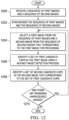
- FIG. 12 an illustration of a process for identifying candidate chips in images is depicted in the form of a flowchart in accordance with an illustrative embodiment.
- the process illustrated in Figure 12 may be implemented using image processor 122 as described in Figures 1-3 .
- the process begins by receiving a sequence of first images and a sequence of second images (operation 1200).
- the sequence of first images and the sequence of second images are synchronized (operation 1202).
- Operation 1202 may be performed such that the sequence of first images and the sequence of second images are synchronized with respect to time. In some cases, this synchronization may also include aligning the sequence of first images and the sequence of second images with respect to a reference coordinate system.
- a first image is selected from the sequence of first images and a second image is selected from the sequence of second images that corresponds to the first image for processing (operation 1204).
- a set of first candidate chips is identified in the first image using a moving target detection process (operation 1206).
- a set of second candidate chips that corresponds to the set of first candidate chips is identified in the second image (operation 1208).
- FIG. 13 an illustration of a process for generating a first score for a first candidate chip is depicted in the form of a flowchart in accordance with an illustrative embodiment.
- the process illustrated in Figure 13 may be implemented using scorer 124 described in Figures 1-3 . Further, this process may be an example one manner in which operation 1102 in Figure 11 may be implemented.
- the process may begin by dividing a first candidate chip into a grid of cells (operation 1300).
- the first candidate chip may be, for example, one of the set of first candidate chips identified in operation 1206 in Figure 12 .
- a plurality of sub-regions is identified within the first candidate chip using a number of sub-region masks (operation 1302). Each of the number of sub-region masks in operation 1302 may have different dimensions.
- a signature is computed for each of the plurality of sub-regions to form a plurality of signatures (operation 1304).
- a plurality of reference sub-regions is identified in a first reference chip that captures a target of interest based on the number of sub-region masks (operation 1306).
- Each sub-region of the plurality of sub-regions is paired with each reference sub-region of the plurality of reference sub-regions to form a plurality of pairs (operation 1308).
- Each of the plurality of pairs is scored to form a plurality of initial scores (operation 1310).
- each of the plurality of initial scores may be generated based on Kullback-Leibler Divergence (KLD).
- KLD T , K i , j 0.5 ⁇ KLD T K i j + KLD K T j i
- KLD T K i j log det C T i det C K j + trace C T i ⁇ 1 C k j + f T i ⁇ f K j C T i ⁇ 1 f T i ⁇ f K j T
- KLD K T j i log det C K j det C T i + trace C K j ⁇ 1 C T i + f K j ⁇ f T i C K j ⁇ 1 f K j ⁇ f T i K
- T is the target of interest and corresponds to the first reference chip
- K is the candidate target and corresponds to the first candidate chip
- i is the target of interest and corresponds to the first candidate chip
- the best initial score for the best matched pair is assigned as a first score for the first candidate chip and, thereby, the candidate target captured in the first candidate chip (operation 1314), with the process terminating thereafter.
- the process described in Figure 13 may be repeated for each first candidate chip in the set of first candidate chips identified.
- FIG. 14 an illustration of a process for generating a second score for a second candidate chip is depicted in the form of a flowchart in accordance with an illustrative embodiment.
- the process illustrated in Figure 14 may be implemented using scorer 124 and image processor 122 described in Figures 1-3 . Further, this process may be an example of one manner in which operation 1104 in Figure 11 may be implemented.
- the process begins by identifying a second candidate chip in a second image that corresponds to a first candidate chip in a first image for which a first score has been generated (operation 1400). Then, a sub-region within the second candidate chip that corresponds to the best matched sub-region within the first candidate chip is identified (operation 1402). In some cases, in operation 1402, the entire second candidate chip may form the sub-region.
- a base histogram vector is created for the sub-region in the second candidate chip in which the base histogram vector comprises a plurality of cell vectors corresponding to a plurality of cells in the sub-region (operation 1404).
- a number of rotational shifts are performed using the base histogram vector to form a plurality of histogram vectors that includes the base histogram vector (operation 1406).
- a reference histogram vector is identified for a best matched reference subregion of a second reference chip (operation 1408).
- the reference histogram vector may be paired with each of the plurality of histogram vectors to form a plurality of pairings (operation 1410).
- a matching score is computed for each pairing of the plurality of pairings to form a plurality of matching scores for the sub-region (operation 1412).
- a best matching score is selected from the plurality of matching scores for the subregion as a second score for the second candidate chip, and thereby, the candidate target (operation 1414), with the process terminating thereafter.
- the best matching score may be the minimum value for each r th rotation. This process may be repeated for each of the set of second candidate chips identified.
- FIG. 15 an illustration of a process for tracking a target of interest is depicted in the form of a flowchart in accordance with an illustrative embodiment. The process may be implemented using scorer 124 and target manager 126 described in Figures 1- 3.
- the process may begin by selecting a first score from a set of first scores corresponding to a candidate target of a set of candidate targets and a second score from a set of second scores corresponding to the candidate target (operation 1500).
- the first score may be multiplied by the second score to obtain a final score for the candidate target (operation 1502).
- an indication that the target of interest has not been detected is generated (operation 1510), with the process terminating thereafter. Otherwise, the candidate target having a best final score in the portion of the set of final scores that is within the selected tolerances is identified as the target of interest (operation 1512), with the process terminating thereafter.
- each block in the flowcharts or block diagrams may represent a module, a segment, a function, and/or a portion of an operation or step.
- the function or functions noted in the blocks may occur out of the order noted in the figures.
- two blocks shown in succession may be executed substantially concurrently, or the blocks may sometimes be performed in the reverse order, depending upon the functionality involved.
- other blocks may be added in addition to the illustrated blocks in a flowchart or block diagram.
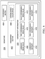
- Data processing system 1600 may be used to implement computer system 102 in Figure 1 .
- data processing system 1600 includes communications framework 1602, which provides communications between processor unit 1604, storage devices 1606, communications unit 1608, input/output unit 1610, and display 1612.
- communications framework 1602 may be implemented as a bus system.
- Processor unit 1604 is configured to execute instructions for software to perform a number of operations.
- Processor unit 1604 may comprise a number of processors, a multiprocessor core, and/or some other type of processor, depending on the implementation.
- processor unit 1604 may take the form of a hardware unit, such as a circuit system, an application specific integrated circuit (ASIC), a programmable logic device, or some other suitable type of hardware unit.
- ASIC application specific integrated circuit
- Storage devices 1606 may be in communication with processor unit 1604 through communications framework 1602.
- a storage device also referred to as a computer readable storage device, is any piece of hardware capable of storing information on a temporary and/or permanent basis. This information may include, but is not limited to, data, program code, and/or other information.
- Memory 1614 and persistent storage 1616 are examples of storage devices 1606.
- Memory 1614 may take the form of, for example, a random access memory or some type of volatile or non-volatile storage device.
- Persistent storage 1616 may comprise any number of components or devices.
- persistent storage 1616 may comprise a hard drive, a flash memory, a rewritable optical disk, a rewritable magnetic tape, or some combination of the above.
- the media used by persistent storage 1616 may or may not be removable.
- Communications unit 1608 allows data processing system 1600 to communicate with other data processing systems and/or devices. Communications unit 1608 may provide communications using physical and/or wireless communications links.
- Input/output unit 1610 allows input to be received from and output to be sent to other devices connected to data processing system 1600.
- input/output unit 1610 may allow user input to be received through a keyboard, a mouse, and/or some other type of input device.
- input/output unit 1610 may allow output to be sent to a printer connected to data processing system 1600.
- Display 1612 is configured to display information to a user.
- Display 1612 may comprise, for example, without limitation, a monitor, a touch screen, a laser display, a holographic display, a virtual display device, and/or some other type of display device.
- processor unit 1604 may perform the processes of the different illustrative embodiments using computer-implemented instructions. These instructions may be referred to as program code, computer usable program code, or computer readable program code and may be read and executed by one or more processors in processor unit 1604.
- program code 1618 is located in a functional form on computer readable media 1620, which is selectively removable, and may be loaded onto or transferred to data processing system 1600 for execution by processor unit 1604.
- Program code 1618 and computer readable media 1620 together form computer program product 1622.
- computer readable media 1620 may be computer readable storage media 1624 or computer readable signal media 1626.
- Computer readable storage media 1624 is a physical or tangible storage device used to store program code 1618 rather than a medium that propagates or transmits program code 1618.
- Computer readable storage media 1624 may be, for example, without limitation, an optical or magnetic disk or a persistent storage device that is connected to data processing system 1600.
- program code 1618 may be transferred to data processing system 1600 using computer readable signal media 1626.
- Computer readable signal media 1626 may be, for example, a propagated data signal containing program code 1618. This data signal may be an electromagnetic signal, an optical signal, and/or some other type of signal that can be transmitted over physical and/or wireless communications links.
- data processing system 1600 in Figure 16 is not meant to provide architectural limitations to the manner in which the illustrative embodiments may be implemented.
- the different illustrative embodiments may be implemented in a data processing system that includes components in addition to or in place of those illustrated for data processing system 1600. Further, components shown in Figure 16 may be varied from the illustrative examples shown.
Landscapes
- Engineering & Computer Science (AREA)
- Theoretical Computer Science (AREA)
- Physics & Mathematics (AREA)
- General Physics & Mathematics (AREA)
- Multimedia (AREA)
- Computer Vision & Pattern Recognition (AREA)
- Data Mining & Analysis (AREA)
- Evolutionary Computation (AREA)
- Artificial Intelligence (AREA)
- Life Sciences & Earth Sciences (AREA)
- General Engineering & Computer Science (AREA)
- Evolutionary Biology (AREA)
- Bioinformatics & Computational Biology (AREA)
- Bioinformatics & Cheminformatics (AREA)
- General Health & Medical Sciences (AREA)
- Health & Medical Sciences (AREA)
- Software Systems (AREA)
- Medical Informatics (AREA)
- Computing Systems (AREA)
- Databases & Information Systems (AREA)
- Image Analysis (AREA)
- Studio Devices (AREA)
Claims (8)
- Computerimplementiertes Verfahren zum Verarbeiten von Bildern, um ein Ziel von Interesse zu verfolgen, wobei das Verfahren umfasst:Synchronisieren (1202), durch einen Bildprozessor (122), einer Folge von ersten Bildern (104), die ein erstes Bild (128) einschließt, mit einer Folge von zweiten Bildern (106), die ein zweites Bild (130) einschließt;Identifizieren (1100, 1206, 1208), durch den Bildprozessor (122), eines Satzes von Kandidatenzielen (136) in dem ersten Bild (128) und in dem zweiten Bild (130), das im Wesentlichen zum selben Zeitpunkt wie das erste Bild (128) erzeugt wurde, wobei die Kandidatenziele (136) sich bewegende Objekte sind und wobei das erste Bild (128) ein elektrooptisches Bild (132) und das zweite Bild (130) ein Infrarotbild (134) ist,wobei das Identifizieren (1100) des Satzes von Kandidatenzielen (136) umfasst:Identifizieren eines Satzes von ersten Kandidatenchips (138) in dem elektrooptischen Bild (132), wobei jeder aus dem Satz von ersten Kandidatenchips (138) ein entsprechendes Kandidatenziel aus dem Satz von Kandidatenzielen (136) erfasst; undIdentifizieren eines Satzes von zweiten Kandidatenchips (140) in dem Infrarotbild (134), wobei jeder aus dem Satz von zweiten Kandidatenchips (140) einem aus dem Satz von ersten Kandidatenchips (138) entspricht;Erzeugen (1102), durch einen Bewerter (124), eines Satzes von ersten Punktwerten (142) für den Satz von Kandidatenzielen (136) unter Verwendung von Chromatizitätsinformationen, die unter Verwendung des ersten elektrooptischen Bildes (128) identifiziert werden;wobei das Erzeugen (1102) des Satzes von ersten Punktwerten (142) umfasst:Identifizieren (1302) einer Vielzahl von Subregionen (214) innerhalb eines ersten Kandidatenchips (204) aus dem Satz von ersten Kandidatenchips (138), wobei der erste Kandidatenchip (204) ein Kandidatenziel (202) aus dem Satz von Kandidatenzielen (136) erfasst;Berechnen (1304) einer Signatur (224) für jede der Vielzahl von Subregionen (214), um eine Vielzahl von Signaturen (218) zu bilden;Paaren (1308) jeder Subregion der Vielzahl von Subregionen (214) mit jeder Referenzsubregion einer Vielzahl von Referenzsubregionen (226) in einem ersten Referenzchip, um eine Vielzahl von Paaren (228) zu bilden, wobei der erste Referenzchip ein erster Kandidatenchip aus einem zuvor verarbeiteten ersten Bild in einer Folge von ersten Bildern (104) ist, der zuvor als das Ziel von Interesse (120) erfassend identifiziert wurde;Bewerten (1310) jedes der Vielzahl von Paaren (228), um eine Vielzahl von Ausgangspunktwerten (230) zu bilden, wobei jeder Ausgangspunktwert (230) ein Maß für den Grad der Übereinstimmung ist zwischen der Subregion (214) und der Referenzsubregion (226) in diesem Paar (228), mindestens in Bezug auf die Chromatizität; undAuswählen (1312) eines Paares aus der Vielzahl von Paaren (228) mit dem besten Ausgangspunktwert (232) der Vielzahl von Ausgangspunktwerten (230) als am besten übereinstimmendes Paar (234), wobei das am besten übereinstimmende Paar (234) eine am besten übereinstimmende Subregion (236) und eine am besten übereinstimmende Referenzsubregion (238) einschließt und wobei der beste Ausgangspunktwert (232) zu einem ersten Punktwert (206) für das im ersten Kandidatenchip (204) erfasste Kandidatenziel (202) wird, wobei die Subregionen (214, 226) durch Bewegen von mindestens einer Subregionsmaske (212) über den ersten Kandidatenchip (204) bzw. den ersten Referenzchip (148) identifiziert werden;Erzeugen (1104), durch den Bewerter (124), eines Satzes zweiter Punktwerte (144) für den Satz von Kandidatenzielen (136) unter Verwendung von Forminformationen, die unter Verwendung des zweiten Infrarotbildes (130) identifiziert werden;wobei das Erzeugen (1104) des Satzes von zweiten Punktwerten (144) umfasst:Identifizieren (1400) eines zweiten Kandidatenchips (300) in dem zweiten Bild (130), der dem ersten Kandidatenchip (204) entspricht;Identifizieren (1402) einer Subregion (306) innerhalb des zweiten Kandidatenchips (300), der der am besten übereinstimmenden Subregion (236) innerhalb des ersten Kandidatenchips (204) entspricht;Erstellen (1404) eines Basishistogrammvektors (312) für die Subregion (306);Durchführen (1406) einer Anzahl von Rotationsverschiebungen (316) unter Verwendung des Basishistogrammvektors (312), um eine Vielzahl von Histogrammvektoren (318) zu bilden, die den Basishistogrammvektor (312) einschließen;Erzeugen eines zweiten Punktwertes (310) für das Kandidatenziel (202) innerhalb des zweiten Kandidatenchips (300) durch Berechnen (1412) eines Übereinstimmungspunktwertes (324) zwischen einem Referenzhistogrammvektor (320) für die am besten übereinstimmende Referenzsubregion (238) und der Vielzahl von Histogrammvektoren (318);Berechnen (1106), durch den Bewerter (124), eines Satzes endgültiger Punktwerte (146) für den Satz von Kandidatenzielen (136) unter Verwendung des Satzes erster Punktwerte (142) und des Satzes zweiter Punktwerte (144); undBestimmen (1108), durch einen Zielmanager (126), welches aus dem Satz der Kandidatenziele (136) das Ziel von Interesse (120) ist, basierend auf dem Satz endgültiger Punktwerte (146).
- Computerimplementiertes Verfahren nach Anspruch 1, ferner umfassend:
Auswählen (1414) eines am besten übereinstimmenden Punktwertes (326) aus der Vielzahl von Übereinstimmungspunktwerten (322) für die Subregion (306) als den zweiten Punktwert (310) für das Kandidatenziel (202). - Computerimplementiertes Verfahren nach Anspruch 1 oder 2, wobei das Berechnen (1106) des Satzes endgültiger Punktwerte (146) umfasst:
Multiplizieren (1502) eines ersten Punktwertes (206) aus dem Satz erster Punktwerte (142) für ein Kandidatenziel (202) aus dem Satz von Kandidatenzielen (136) mit einem zweiten Punktwert (310) aus dem Satz zweiter Punktwerte (144) für das Kandidatenziel (202), um einen endgültigen Punktwert (332) für das Kandidatenziel (202) zu bilden. - Computerimplementiertes Verfahren nach einem der vorstehenden Ansprüche, ferner umfassend:
Identifizieren, durch den Bildprozessor (122), eines Referenzkoordinatensystems (127) sowohl für das erste Bild (128) als auch für das zweite Bild (130). - Vorrichtung zum Verfolgen eines Ziels von Interesse, umfassend:einen Bildprozessor (122), der eine Folge elektrooptischer Bilder (116) mit einer Folge von Infrarotbildern (118) synchronisiert und der ferner einen Satz von Kandidatenzielen (136) in einem ersten Bild (128) und in einem zweiten Bild (130) identifiziert, das im Wesentlichen zum selben Zeitpunkt wie das erste Bild (128) erzeugt wurde, wobei das erste Bild (128) ein elektrooptisches Bild (132) aus der Folge elektrooptischer Bilder (116) ist und das zweite Bild (130) ein Infrarotbild (134) ist, das in der Folge von Infrarotbildern (118) eingeschlossen ist;wobei das Identifizieren (1100) des Satzes von Kandidatenzielen (136) durch den Bildprozessor (122) umfasst:Identifizieren eines Satzes von ersten Kandidatenchips (138) in dem elektrooptischen Bild (132), wobei jeder aus dem Satz von ersten Kandidatenchips (138) ein entsprechendes Kandidatenziel aus dem Satz von Kandidatenzielen (136) erfasst; undIdentifizieren eines Satzes von zweiten Kandidatenchips (140) im Infrarotbild (134), wobei jeder aus dem Satz von zweiten Kandidatenchips (140) einem aus dem Satz von ersten Kandidatenchips (138) entspricht;ein Bewerter (124), der:einen Satz von ersten Punktwerten (142) für den Satz von Kandidatenzielen (136) unter Verwendung von Chromatizitätsinformationen erzeugt, die unter Verwendung des ersten elektrooptischen Bildes (128) identifiziert werden;wobei das Erzeugen (1102) des Satzes von ersten Punktwerten (142) durch den Bewerter (124) umfasst:Identifizieren (1302) einer Vielzahl von Subregionen (214) innerhalb eines ersten Kandidatenchips (204) aus dem Satz von ersten Kandidatenchips (138), wobei der erste Kandidatenchip (204) ein Kandidatenziel (202) aus dem Satz von Kandidatenzielen (136) erfasst;Berechnen (1304) einer Signatur (224) für jede der Vielzahl von Subregionen (214), um eine Vielzahl von Signaturen (218) zu bilden;Paaren (1308) jeder Subregion der Vielzahl von Subregionen (214) mit jeder Referenzsubregion einer Vielzahl von Referenzsubregionen (226) in einem ersten Referenzchip, um eine Vielzahl von Paaren (228) zu bilden, wobei der erste Referenzchip ein erster Kandidatenchip aus einem zuvor verarbeiteten ersten Bild in einer Folge von ersten Bildern (104) ist, der zuvor als das Ziel von Interesse (120) erfassend identifiziert wurde;Bewerten (1310) jedes der Vielzahl von Paaren (228), um eine Vielzahl von Ausgangspunktwerten (230) zu bilden, wobei jeder Ausgangspunktwert (230) ein Maß für den Grad der Übereinstimmung zwischen der Subregion (214) und der Referenzsubregion (226) in diesem Paar (228) mindestens in Bezug auf die Chromatizität ist; undAuswählen (1312) eines Paares aus der Vielzahl von Paaren (228) mit dem besten Ausgangspunktwert (232) der Vielzahl von Ausgangspunktwerten (230) als am besten übereinstimmendes Paar (234), wobei das am besten übereinstimmende Paar (234) eine am besten übereinstimmende Subregion (236) und eine am besten übereinstimmende Referenzsubregion (238) einschließt und wobei der beste Ausgangspunktwert (232) zu einem ersten Punktwert (206) für das im ersten Kandidatenchip (204) erfasste Kandidatenziel (202) wird, wobei die Subregionen (214, 226) durch Bewegen von mindestens einer Subregionsmaske (212) über den ersten Kandidatenchip (204) bzw. den ersten Referenzchip (148) identifiziert werden;einen Satz von zweiten Punktwerten (144) für den Satz von Kandidatenzielen (136) unter Verwendung von Forminformationen erzeugt, die unter Verwendung des zweiten Infrarotbildes (130) identifiziert werden;wobei das Erzeugen (1104) des Satzes von zweiten Punktwerten (144) umfasst:Identifizieren (1400) eines zweiten Kandidatenchips (300) in dem zweiten Bild (130), der dem ersten Kandidatenchip (204) entspricht;Identifizieren (1402) einer Subregion (306) innerhalb des zweiten Kandidatenchips (300), der der am besten übereinstimmenden Subregion (236) innerhalb des ersten Kandidatenchips (204) entspricht;Erstellen (1404) eines Basishistogrammvektors (312) für die Subregion (306);Durchführen (1406) einer Anzahl von Rotationsverschiebungen (316) unter Verwendung des Basishistogrammvektors (312), um eine Vielzahl von Histogrammvektoren (318) zu bilden, die den Basishistogrammvektor (312) einschließen;Erzeugen eines zweiten Punktwertes (310) für das Kandidatenziel (202) innerhalb des zweiten Kandidatenchips (300) durch Berechnen (1412) eines Übereinstimmungspunktwertes (324) zwischen einem Referenzhistogrammvektor (320) für die am besten übereinstimmende Referenzsubregion (238) und der Vielzahl von Histogrammvektoren (318); undunter Verwendung des Satzes der ersten Punktwerte (142) und des Satzes der zweiten Punktwerte (144) einen Satz endgültiger Punktwerte (146) für den Satz von Kandidatenzielen (136) berechnet; undeinen Zielmanager (126), der basierend auf dem Satz der endgültigen Punktwerte (146) bestimmt, welches aus dem Satz der Kandidatenziele (136) das Ziel von Interesse (120) ist.
- Vorrichtung nach Anspruch 5, wobei der Bewerter (124) ferner einen am besten übereinstimmenden Punktwert (326) aus der Vielzahl von Übereinstimmungspunktwerten (322) für die Subregion (306) als den zweiten Punktwert (310) für das Kandidatenziel (202) auswählt (1414).
- Vorrichtung nach Anspruch 5 oder 6, wobei der Bewerter (124) den Satz endgültiger Punktwerte (146) berechnet, indem er einen ersten Punktwert (206) des Satzes von ersten Punktwerten (142) für ein Kandidatenziel (202) des Satzes von Kandidatenzielen (136) mit einem zweiten Punktwert (310) des Satzes von zweiten Punktwerten (144) für das Kandidatenziel (202) multipliziert (1502), um einen endgültigen Punktwert (332) für das Kandidatenziel (202) zu bilden.
- Vorrichtung nach einem der Ansprüche 5 bis 7, wobei der Bildprozessor (122) ferner ein Referenzkoordinatensystem (127) sowohl für das erste Bild (128) als auch für das zweite Bild (130) identifiziert.
Applications Claiming Priority (1)
| Application Number | Priority Date | Filing Date | Title |
|---|---|---|---|
| US14/743,349 US9727785B2 (en) | 2015-06-18 | 2015-06-18 | Method and apparatus for tracking targets |
Publications (2)
| Publication Number | Publication Date |
|---|---|
| EP3107039A1 EP3107039A1 (de) | 2016-12-21 |
| EP3107039B1 true EP3107039B1 (de) | 2025-01-29 |
Family
ID=56497533
Family Applications (1)
| Application Number | Title | Priority Date | Filing Date |
|---|---|---|---|
| EP16175214.2A Active EP3107039B1 (de) | 2015-06-18 | 2016-06-20 | Verfahren und vorrichtung zur verfolgung von zielen |
Country Status (3)
| Country | Link |
|---|---|
| US (1) | US9727785B2 (de) |
| EP (1) | EP3107039B1 (de) |
| JP (1) | JP6806459B2 (de) |
Families Citing this family (7)
| Publication number | Priority date | Publication date | Assignee | Title |
|---|---|---|---|---|
| US9715639B2 (en) | 2015-06-18 | 2017-07-25 | The Boeing Company | Method and apparatus for detecting targets |
| CN105654092B (zh) * | 2015-11-25 | 2019-08-30 | 小米科技有限责任公司 | 特征提取方法及装置 |
| US10942029B2 (en) * | 2016-11-04 | 2021-03-09 | The Boeing Company | Tracking a target using multiple tracking systems |
| US10606266B2 (en) | 2016-11-04 | 2020-03-31 | The Boeing Company | Tracking a target moving between states in an environment |
| CN111292352B (zh) * | 2020-01-20 | 2023-08-25 | 杭州电子科技大学 | 多目标跟踪方法、装置、设备及存储介质 |
| US11983883B2 (en) | 2020-12-15 | 2024-05-14 | The Boeing Company | Intensity-based image modification for computer vision |
| US12086970B2 (en) | 2020-12-17 | 2024-09-10 | The Boeing Company | Intensity thresholding-based image modification for computer vision |
Family Cites Families (26)
| Publication number | Priority date | Publication date | Assignee | Title |
|---|---|---|---|---|
| US6704466B1 (en) * | 1998-08-31 | 2004-03-09 | Canon Kabushiki Kaisha | Image search system, image search apparatus, control method thereof, and computer readable memory |
| CA2296143A1 (fr) * | 2000-01-18 | 2001-07-18 | 9071 9410 Quebec Inc. | Systeme d'inspection optique |
| JP2002157599A (ja) * | 2000-11-17 | 2002-05-31 | Nippon Telegr & Teleph Corp <Ntt> | 物体検出認識方法,物体検出認識プログラムを記録した記録媒体および物体監視追跡装置 |
| US7545967B1 (en) * | 2002-09-18 | 2009-06-09 | Cornell Research Foundation Inc. | System and method for generating composite subtraction images for magnetic resonance imaging |
| JP3931879B2 (ja) * | 2003-11-28 | 2007-06-20 | 株式会社デンソー | センサフュージョンシステム及びそれを用いた車両制御装置 |
| US7522779B2 (en) * | 2004-06-30 | 2009-04-21 | Accuray, Inc. | Image enhancement method and system for fiducial-less tracking of treatment targets |
| DE102005011237B3 (de) * | 2005-03-11 | 2006-08-03 | Leica Microsystems Semiconductor Gmbh | Verfahren zur Bestimmung von Defekten in Bildern |
| US7936903B2 (en) * | 2005-05-31 | 2011-05-03 | Koninklijke Philips Electronics N.V. | Method and a system for detecting a road at night |
| WO2007032082A1 (ja) * | 2005-09-16 | 2007-03-22 | Fujitsu Limited | 画像処理方法及び画像処理装置 |
| US20080112593A1 (en) | 2006-11-03 | 2008-05-15 | Ratner Edward R | Automated method and apparatus for robust image object recognition and/or classification using multiple temporal views |
| US20080205755A1 (en) | 2007-02-23 | 2008-08-28 | Banner Engineering Corporation | Method and apparatus for color matching |
| US8553984B2 (en) | 2008-06-02 | 2013-10-08 | Massachusetts Institute Of Technology | Fast pattern classification based on a sparse transform |
| US8243991B2 (en) | 2008-06-17 | 2012-08-14 | Sri International | Method and apparatus for detecting targets through temporal scene changes |
| JP5275017B2 (ja) * | 2008-12-25 | 2013-08-28 | 株式会社日立ハイテクノロジーズ | 欠陥検査方法及びその装置 |
| US8131786B1 (en) * | 2009-11-23 | 2012-03-06 | Google Inc. | Training scoring models optimized for highly-ranked results |
| US8615105B1 (en) | 2010-08-31 | 2013-12-24 | The Boeing Company | Object tracking system |
| WO2012057779A1 (en) | 2010-10-29 | 2012-05-03 | Analogic Corporation | Object identification using sparse spectral components |
| US8818105B2 (en) * | 2011-07-14 | 2014-08-26 | Accuray Incorporated | Image registration for image-guided surgery |
| US8861893B2 (en) | 2011-09-27 | 2014-10-14 | The Boeing Company | Enhancing video using super-resolution |
| US8891820B2 (en) * | 2011-09-29 | 2014-11-18 | The Boeing Company | Multi-modal sensor fusion |
| US8774510B2 (en) | 2012-09-11 | 2014-07-08 | Sharp Laboratories Of America, Inc. | Template matching with histogram of gradient orientations |
| US9036910B1 (en) | 2012-09-28 | 2015-05-19 | The Boeing Company | Method and system for processing a sequence of images using fingerprints |
| JP6265641B2 (ja) * | 2013-07-24 | 2018-01-24 | オリンパス株式会社 | 画像処理装置、画像処理方法及び画像処理プログラム |
| US9405974B2 (en) | 2013-11-13 | 2016-08-02 | Xerox Corporation | System and method for using apparent size and orientation of an object to improve video-based tracking in regularized environments |
| CN104715249B (zh) | 2013-12-16 | 2018-06-05 | 株式会社理光 | 物体跟踪方法和装置 |
| US9715639B2 (en) | 2015-06-18 | 2017-07-25 | The Boeing Company | Method and apparatus for detecting targets |
-
2015
- 2015-06-18 US US14/743,349 patent/US9727785B2/en active Active
-
2016
- 2016-04-13 JP JP2016080172A patent/JP6806459B2/ja active Active
- 2016-06-20 EP EP16175214.2A patent/EP3107039B1/de active Active
Also Published As
| Publication number | Publication date |
|---|---|
| JP2017010527A (ja) | 2017-01-12 |
| US9727785B2 (en) | 2017-08-08 |
| US20160371530A1 (en) | 2016-12-22 |
| JP6806459B2 (ja) | 2021-01-06 |
| EP3107039A1 (de) | 2016-12-21 |
Similar Documents
| Publication | Publication Date | Title |
|---|---|---|
| EP3107039B1 (de) | Verfahren und vorrichtung zur verfolgung von zielen | |
| US9715639B2 (en) | Method and apparatus for detecting targets | |
| US9754192B2 (en) | Object detection utilizing geometric information fused with image data | |
| EP2713308B1 (de) | Verfahren und System zur Verwendung von Fingerabdrücken zum Verfolgen beweglicher Objekte in Videos | |
| CN110163899B (zh) | 图像匹配方法和图像匹配装置 | |
| US9373174B2 (en) | Cloud based video detection and tracking system | |
| EP3410396B1 (de) | Vorrichtung zur verfolgung eines sich bewegenden objekts, verfahren zur verfolgung eines sich bewegenden objekts und computerlesbares medium | |
| JP2014071902A5 (de) | ||
| US10679098B2 (en) | Method and system for visual change detection using multi-scale analysis | |
| JP5936561B2 (ja) | 画像における外観及びコンテキストに基づく物体分類 | |
| Trinh et al. | Efficient UAV video event summarization | |
| Bhattacharya et al. | Moving object detection and tracking in forward looking infra-red aerial imagery | |
| CN117765243B (zh) | 一种基于高性能计算架构的ai导引系统 | |
| Jabar et al. | Object tracking using SIFT and KLT tracker for UAV-based applications | |
| Hoang et al. | Scalable histogram of oriented gradients for multi-size car detection | |
| EP3044734B1 (de) | Isotropiemerkmalsanpassung | |
| Demars et al. | Multispectral detection and tracking of multiple moving targets in cluttered urban environments | |
| KR20160148806A (ko) | 방향정보를 이용한 객체 검출기 생성 방법, 이를 이용한 객체 검출 장치 및 방법 | |
| US9111361B1 (en) | Distinguishing between moving targets and clutter in a video | |
| Islam et al. | A new method for road surface detection | |
| KR101175751B1 (ko) | 스트랩다운 이중 모드 영상탐색기의 베이시안 규칙 기반 표적 결정 방법 | |
| Yang et al. | Method for building recognition from FLIR images | |
| Husain et al. | Moving vehicle detection and tracking under hazy environment for traffic surveillance system | |
| Bouachir et al. | Exploiting structural constraints for visual object tracking | |
| Masum et al. | Vehicle re-identification for intelligent transport system using dolgnet attention model |
Legal Events
| Date | Code | Title | Description |
|---|---|---|---|
| PUAI | Public reference made under article 153(3) epc to a published international application that has entered the european phase |
Free format text: ORIGINAL CODE: 0009012 |
|
| STAA | Information on the status of an ep patent application or granted ep patent |
Free format text: STATUS: REQUEST FOR EXAMINATION WAS MADE |
|
| 17P | Request for examination filed |
Effective date: 20160620 |
|
| AK | Designated contracting states |
Kind code of ref document: A1 Designated state(s): AL AT BE BG CH CY CZ DE DK EE ES FI FR GB GR HR HU IE IS IT LI LT LU LV MC MK MT NL NO PL PT RO RS SE SI SK SM TR |
|
| AX | Request for extension of the european patent |
Extension state: BA ME |
|
| STAA | Information on the status of an ep patent application or granted ep patent |
Free format text: STATUS: EXAMINATION IS IN PROGRESS |
|
| 17Q | First examination report despatched |
Effective date: 20210115 |
|
| RAP3 | Party data changed (applicant data changed or rights of an application transferred) |
Owner name: THE BOEING COMPANY |
|
| REG | Reference to a national code |
Ref legal event code: R079 Ipc: G06T0007246000 Ref country code: DE Ref legal event code: R079 Ref document number: 602016091072 Country of ref document: DE Free format text: PREVIOUS MAIN CLASS: G06K0009320000 Ipc: G06T0007246000 |
|
| RIC1 | Information provided on ipc code assigned before grant |
Ipc: G06V 10/75 20220101ALN20240709BHEP Ipc: G06F 18/25 20230101ALI20240709BHEP Ipc: G06V 20/54 20220101ALI20240709BHEP Ipc: G06V 20/52 20220101ALI20240709BHEP Ipc: G06V 10/80 20220101ALI20240709BHEP Ipc: G06V 10/143 20220101ALI20240709BHEP Ipc: G06T 7/246 20170101AFI20240709BHEP |
|
| GRAP | Despatch of communication of intention to grant a patent |
Free format text: ORIGINAL CODE: EPIDOSNIGR1 |
|
| STAA | Information on the status of an ep patent application or granted ep patent |
Free format text: STATUS: GRANT OF PATENT IS INTENDED |
|
| INTG | Intention to grant announced |
Effective date: 20240820 |
|
| GRAS | Grant fee paid |
Free format text: ORIGINAL CODE: EPIDOSNIGR3 |
|
| GRAA | (expected) grant |
Free format text: ORIGINAL CODE: 0009210 |
|
| STAA | Information on the status of an ep patent application or granted ep patent |
Free format text: STATUS: THE PATENT HAS BEEN GRANTED |
|
| AK | Designated contracting states |
Kind code of ref document: B1 Designated state(s): AL AT BE BG CH CY CZ DE DK EE ES FI FR GB GR HR HU IE IS IT LI LT LU LV MC MK MT NL NO PL PT RO RS SE SI SK SM TR |
|
| REG | Reference to a national code |
Ref country code: GB Ref legal event code: FG4D |
|
| REG | Reference to a national code |
Ref country code: CH Ref legal event code: EP |
|
| REG | Reference to a national code |
Ref country code: DE Ref legal event code: R096 Ref document number: 602016091072 Country of ref document: DE |
|
| P01 | Opt-out of the competence of the unified patent court (upc) registered |
Free format text: CASE NUMBER: APP_3020/2025 Effective date: 20250120 |
|
| REG | Reference to a national code |
Ref country code: IE Ref legal event code: FG4D |
|
| REG | Reference to a national code |
Ref country code: NL Ref legal event code: MP Effective date: 20250129 |
|
| PG25 | Lapsed in a contracting state [announced via postgrant information from national office to epo] |
Ref country code: NL Free format text: LAPSE BECAUSE OF FAILURE TO SUBMIT A TRANSLATION OF THE DESCRIPTION OR TO PAY THE FEE WITHIN THE PRESCRIBED TIME-LIMIT Effective date: 20250129 |
|
| PG25 | Lapsed in a contracting state [announced via postgrant information from national office to epo] |
Ref country code: RS Free format text: LAPSE BECAUSE OF FAILURE TO SUBMIT A TRANSLATION OF THE DESCRIPTION OR TO PAY THE FEE WITHIN THE PRESCRIBED TIME-LIMIT Effective date: 20250429 |
|
| PG25 | Lapsed in a contracting state [announced via postgrant information from national office to epo] |
Ref country code: FI Free format text: LAPSE BECAUSE OF FAILURE TO SUBMIT A TRANSLATION OF THE DESCRIPTION OR TO PAY THE FEE WITHIN THE PRESCRIBED TIME-LIMIT Effective date: 20250129 |
|
| PG25 | Lapsed in a contracting state [announced via postgrant information from national office to epo] |
Ref country code: PL Free format text: LAPSE BECAUSE OF FAILURE TO SUBMIT A TRANSLATION OF THE DESCRIPTION OR TO PAY THE FEE WITHIN THE PRESCRIBED TIME-LIMIT Effective date: 20250129 |
|
| PGFP | Annual fee paid to national office [announced via postgrant information from national office to epo] |
Ref country code: DE Payment date: 20250627 Year of fee payment: 10 |
|
| PG25 | Lapsed in a contracting state [announced via postgrant information from national office to epo] |
Ref country code: ES Free format text: LAPSE BECAUSE OF FAILURE TO SUBMIT A TRANSLATION OF THE DESCRIPTION OR TO PAY THE FEE WITHIN THE PRESCRIBED TIME-LIMIT Effective date: 20250129 |
|
| PGFP | Annual fee paid to national office [announced via postgrant information from national office to epo] |
Ref country code: GB Payment date: 20250627 Year of fee payment: 10 |
|
| REG | Reference to a national code |
Ref country code: LT Ref legal event code: MG9D |
|
| PG25 | Lapsed in a contracting state [announced via postgrant information from national office to epo] |
Ref country code: NO Free format text: LAPSE BECAUSE OF FAILURE TO SUBMIT A TRANSLATION OF THE DESCRIPTION OR TO PAY THE FEE WITHIN THE PRESCRIBED TIME-LIMIT Effective date: 20250429 Ref country code: IS Free format text: LAPSE BECAUSE OF FAILURE TO SUBMIT A TRANSLATION OF THE DESCRIPTION OR TO PAY THE FEE WITHIN THE PRESCRIBED TIME-LIMIT Effective date: 20250529 |
|
| REG | Reference to a national code |
Ref country code: AT Ref legal event code: MK05 Ref document number: 1764212 Country of ref document: AT Kind code of ref document: T Effective date: 20250129 |
|
| PG25 | Lapsed in a contracting state [announced via postgrant information from national office to epo] |
Ref country code: HR Free format text: LAPSE BECAUSE OF FAILURE TO SUBMIT A TRANSLATION OF THE DESCRIPTION OR TO PAY THE FEE WITHIN THE PRESCRIBED TIME-LIMIT Effective date: 20250129 |
|
| PG25 | Lapsed in a contracting state [announced via postgrant information from national office to epo] |
Ref country code: LV Free format text: LAPSE BECAUSE OF FAILURE TO SUBMIT A TRANSLATION OF THE DESCRIPTION OR TO PAY THE FEE WITHIN THE PRESCRIBED TIME-LIMIT Effective date: 20250129 Ref country code: PT Free format text: LAPSE BECAUSE OF FAILURE TO SUBMIT A TRANSLATION OF THE DESCRIPTION OR TO PAY THE FEE WITHIN THE PRESCRIBED TIME-LIMIT Effective date: 20250529 |
|
| PGFP | Annual fee paid to national office [announced via postgrant information from national office to epo] |
Ref country code: FR Payment date: 20250625 Year of fee payment: 10 |
|
| PG25 | Lapsed in a contracting state [announced via postgrant information from national office to epo] |
Ref country code: GR Free format text: LAPSE BECAUSE OF FAILURE TO SUBMIT A TRANSLATION OF THE DESCRIPTION OR TO PAY THE FEE WITHIN THE PRESCRIBED TIME-LIMIT Effective date: 20250430 Ref country code: BG Free format text: LAPSE BECAUSE OF FAILURE TO SUBMIT A TRANSLATION OF THE DESCRIPTION OR TO PAY THE FEE WITHIN THE PRESCRIBED TIME-LIMIT Effective date: 20250129 |
|
| PG25 | Lapsed in a contracting state [announced via postgrant information from national office to epo] |
Ref country code: AT Free format text: LAPSE BECAUSE OF FAILURE TO SUBMIT A TRANSLATION OF THE DESCRIPTION OR TO PAY THE FEE WITHIN THE PRESCRIBED TIME-LIMIT Effective date: 20250129 |
|
| PG25 | Lapsed in a contracting state [announced via postgrant information from national office to epo] |
Ref country code: SE Free format text: LAPSE BECAUSE OF FAILURE TO SUBMIT A TRANSLATION OF THE DESCRIPTION OR TO PAY THE FEE WITHIN THE PRESCRIBED TIME-LIMIT Effective date: 20250129 |
|
| PG25 | Lapsed in a contracting state [announced via postgrant information from national office to epo] |
Ref country code: SM Free format text: LAPSE BECAUSE OF FAILURE TO SUBMIT A TRANSLATION OF THE DESCRIPTION OR TO PAY THE FEE WITHIN THE PRESCRIBED TIME-LIMIT Effective date: 20250129 |
|
| PG25 | Lapsed in a contracting state [announced via postgrant information from national office to epo] |
Ref country code: DK Free format text: LAPSE BECAUSE OF FAILURE TO SUBMIT A TRANSLATION OF THE DESCRIPTION OR TO PAY THE FEE WITHIN THE PRESCRIBED TIME-LIMIT Effective date: 20250129 |
|
| PG25 | Lapsed in a contracting state [announced via postgrant information from national office to epo] |
Ref country code: IT Free format text: LAPSE BECAUSE OF FAILURE TO SUBMIT A TRANSLATION OF THE DESCRIPTION OR TO PAY THE FEE WITHIN THE PRESCRIBED TIME-LIMIT Effective date: 20250129 |
|
| PG25 | Lapsed in a contracting state [announced via postgrant information from national office to epo] |
Ref country code: EE Free format text: LAPSE BECAUSE OF FAILURE TO SUBMIT A TRANSLATION OF THE DESCRIPTION OR TO PAY THE FEE WITHIN THE PRESCRIBED TIME-LIMIT Effective date: 20250129 Ref country code: CZ Free format text: LAPSE BECAUSE OF FAILURE TO SUBMIT A TRANSLATION OF THE DESCRIPTION OR TO PAY THE FEE WITHIN THE PRESCRIBED TIME-LIMIT Effective date: 20250129 |
|
| PG25 | Lapsed in a contracting state [announced via postgrant information from national office to epo] |
Ref country code: RO Free format text: LAPSE BECAUSE OF FAILURE TO SUBMIT A TRANSLATION OF THE DESCRIPTION OR TO PAY THE FEE WITHIN THE PRESCRIBED TIME-LIMIT Effective date: 20250129 |
|
| PG25 | Lapsed in a contracting state [announced via postgrant information from national office to epo] |
Ref country code: SK Free format text: LAPSE BECAUSE OF FAILURE TO SUBMIT A TRANSLATION OF THE DESCRIPTION OR TO PAY THE FEE WITHIN THE PRESCRIBED TIME-LIMIT Effective date: 20250129 |
|
| REG | Reference to a national code |
Ref country code: DE Ref legal event code: R097 Ref document number: 602016091072 Country of ref document: DE |
|
| PLBE | No opposition filed within time limit |
Free format text: ORIGINAL CODE: 0009261 |
|
| STAA | Information on the status of an ep patent application or granted ep patent |
Free format text: STATUS: NO OPPOSITION FILED WITHIN TIME LIMIT |
|
| REG | Reference to a national code |
Ref country code: CH Ref legal event code: L10 Free format text: ST27 STATUS EVENT CODE: U-0-0-L10-L00 (AS PROVIDED BY THE NATIONAL OFFICE) Effective date: 20251210 |
|
| 26N | No opposition filed |
Effective date: 20251030 |
|
| REG | Reference to a national code |
Ref country code: CH Ref legal event code: H13 Free format text: ST27 STATUS EVENT CODE: U-0-0-H10-H13 (AS PROVIDED BY THE NATIONAL OFFICE) Effective date: 20260127 |
|
| PG25 | Lapsed in a contracting state [announced via postgrant information from national office to epo] |
Ref country code: MC Free format text: LAPSE BECAUSE OF FAILURE TO SUBMIT A TRANSLATION OF THE DESCRIPTION OR TO PAY THE FEE WITHIN THE PRESCRIBED TIME-LIMIT Effective date: 20250129 |
|
| PG25 | Lapsed in a contracting state [announced via postgrant information from national office to epo] |
Ref country code: LU Free format text: LAPSE BECAUSE OF NON-PAYMENT OF DUE FEES Effective date: 20250620 |
|
| REG | Reference to a national code |
Ref country code: BE Ref legal event code: MM Effective date: 20250630 |