EP3106675A1 - Vakuumpumpe - Google Patents
Vakuumpumpe Download PDFInfo
- Publication number
- EP3106675A1 EP3106675A1 EP15172540.5A EP15172540A EP3106675A1 EP 3106675 A1 EP3106675 A1 EP 3106675A1 EP 15172540 A EP15172540 A EP 15172540A EP 3106675 A1 EP3106675 A1 EP 3106675A1
- Authority
- EP
- European Patent Office
- Prior art keywords
- bearing
- vacuum pump
- pump according
- receiving space
- axial
- Prior art date
- Legal status (The legal status is an assumption and is not a legal conclusion. Google has not performed a legal analysis and makes no representation as to the accuracy of the status listed.)
- Granted
Links
Images


Classifications
-
- F—MECHANICAL ENGINEERING; LIGHTING; HEATING; WEAPONS; BLASTING
- F04—POSITIVE - DISPLACEMENT MACHINES FOR LIQUIDS; PUMPS FOR LIQUIDS OR ELASTIC FLUIDS
- F04D—NON-POSITIVE-DISPLACEMENT PUMPS
- F04D19/00—Axial-flow pumps
- F04D19/02—Multi-stage pumps
- F04D19/04—Multi-stage pumps specially adapted to the production of a high vacuum, e.g. molecular pumps
- F04D19/042—Turbomolecular vacuum pumps
-
- F—MECHANICAL ENGINEERING; LIGHTING; HEATING; WEAPONS; BLASTING
- F04—POSITIVE - DISPLACEMENT MACHINES FOR LIQUIDS; PUMPS FOR LIQUIDS OR ELASTIC FLUIDS
- F04D—NON-POSITIVE-DISPLACEMENT PUMPS
- F04D29/00—Details, component parts, or accessories
- F04D29/05—Shafts or bearings, or assemblies thereof, specially adapted for elastic fluid pumps
- F04D29/051—Axial thrust balancing
-
- F—MECHANICAL ENGINEERING; LIGHTING; HEATING; WEAPONS; BLASTING
- F04—POSITIVE - DISPLACEMENT MACHINES FOR LIQUIDS; PUMPS FOR LIQUIDS OR ELASTIC FLUIDS
- F04D—NON-POSITIVE-DISPLACEMENT PUMPS
- F04D29/00—Details, component parts, or accessories
- F04D29/05—Shafts or bearings, or assemblies thereof, specially adapted for elastic fluid pumps
- F04D29/056—Bearings
- F04D29/059—Roller bearings
-
- F—MECHANICAL ENGINEERING; LIGHTING; HEATING; WEAPONS; BLASTING
- F04—POSITIVE - DISPLACEMENT MACHINES FOR LIQUIDS; PUMPS FOR LIQUIDS OR ELASTIC FLUIDS
- F04D—NON-POSITIVE-DISPLACEMENT PUMPS
- F04D29/00—Details, component parts, or accessories
- F04D29/60—Mounting; Assembling; Disassembling
- F04D29/64—Mounting; Assembling; Disassembling of axial pumps
- F04D29/642—Mounting; Assembling; Disassembling of axial pumps by adjusting the clearances between rotary and stationary parts
-
- F—MECHANICAL ENGINEERING; LIGHTING; HEATING; WEAPONS; BLASTING
- F04—POSITIVE - DISPLACEMENT MACHINES FOR LIQUIDS; PUMPS FOR LIQUIDS OR ELASTIC FLUIDS
- F04D—NON-POSITIVE-DISPLACEMENT PUMPS
- F04D29/00—Details, component parts, or accessories
- F04D29/66—Combating cavitation, whirls, noise, vibration or the like; Balancing
- F04D29/661—Combating cavitation, whirls, noise, vibration or the like; Balancing especially adapted for elastic fluid pumps
- F04D29/668—Combating cavitation, whirls, noise, vibration or the like; Balancing especially adapted for elastic fluid pumps damping or preventing mechanical vibrations
Definitions
- the present invention relates to a vacuum pump, in particular a turbomolecular pump, a bearing, a vorvakuum solution of a housing of the pump forming body, an integrally formed in the body receiving space for the bearing, at least one axial damping element, which is arranged in the receiving space and the is provided for biasing the bearing in the receiving space, and a separate closing element, with which the receiving space is completed, comprises.
- turbomolecular pumps have a plurality of turbomolecular pumping stages which are pump-connected in series. These are each formed by a rotor disk fastened to a rotor shaft and a stator disk arranged between adjacent rotor disks and fixed in the housing.
- a rolling bearing in the region of a pump outlet and a permanent magnet bearing in the region of a pump inlet are usually provided.
- the nature of the embedding of the bearing in the vacuum pump is of great importance.
- the outlet-side bearing is often embedded or clamped axially and radially in oscillating rings.
- the bearing is granted a certain axial freedom of movement, until at least the axial oscillating ring acts on the bearing.
- it is known to achieve this axial freedom of movement by means of a threaded axial stop.
- the thrust bearing also preloads the bearing in the pump.
- the bearing In contrast, in large turbomolecular pumps, the bearing is usually clamped between vibrating rings within a bearing mount with a certain bias. The finished, pre-assembled bearing holder is then mounted in a vacuum pump.
- turbomolecular pumps In order to make the applications of turbomolecular pumps more flexible, they are increasingly being miniaturized, so that neither a preassembled bearing mount nor a threaded axially adjustable axial stop can be readily integrated.
- Another object of the present invention is to simplify the assembly of a vacuum pump.
- a vacuum pump in particular a turbomolecular pump, which comprises a bearing, in particular a lubricant-supplied bearing, a forvacuum-side part of a housing of the pump forming body, an integrally formed in the body receiving space for the bearing, at least one axial damping element is arranged in the receiving space and is provided for biasing the bearing in the receiving space, and a separate closing element which limits the receiving space in the axial direction comprises.
- the vacuum pump is characterized in that at least one spacer element, in particular a shim, provided is to clamp the bearing in the receiving space in a defined axial position.
- the required preload can be set exactly for each vacuum pump. That for each vacuum pump that is selected from a plurality of differently dimensioned spacer elements, which sets the optimal axial position of the bearing and / or the appropriate bias at a well-defined axial position of the end element.
- the closing element is then simply introduced into the receiving space, for example, until it abuts, and fixed in this position. The position of the stop results - directly or indirectly - from the design of the spacer.
- vacuum pumps can be built with the bearing concept of the invention due to the non-existent adjustable axial stop or the unused, separate storage version with fewer components and in particular smaller and simpler.
- the construction of the receiving space forming body can be simplified, which has an additional positive effect on the manufacturing cost of the vacuum pump. Furthermore, contamination of the bearing by an additional thread in its vicinity, namely the thread of the adjustable axial stop, avoided.
- the bearing is designed as a rolling bearing.
- the rolling bearing is introduced into an integrally formed receiving portion of the base body, which forms the receiving space.
- the bearing is then clamped by the end element in the receiving space.
- the closing element designed as a separate component is introduced into the receiving space from a fore-vacuum-side end face of the main body and fixed there.
- the axial damping element provides a force acting on the bearing, biasing force.
- the spacer element is preferably provided in or on the end element.
- the spacer is e.g. an annular disc, a shim, a disc with at least one hole.
- polygonal (triangular, square and polygonal) shapes are possible, which are automatically arranged against rotation with appropriate geometry of the receiving space.
- the closing element is fixed in the position of use in its axial position and its radial position.
- the end element By fixing the end element in an axial position and its radial position, an adjustment of at least the axial stress is avoided. Furthermore, no adjustable axial stop is required for adjusting the preload.
- the spacer element is arranged between the base body and the closure element.
- the setting of a distance between the main body and the closing element is brought about in a simple manner in order to embed the bearing in the basic body with a defined axial stress.
- the spacer element is supported axially on a support surface arranged on the base body, in particular on an end face.
- the spacing element is arranged between a further axial damping element and the supporting surface or between an axial damping element arranged on the supporting surface and the closing element.
- a further axial damping element allows an even more accurate adjustment of the axial freedom of movement, which may have a bearing to support the rotor shaft during operation of the vacuum pump.
- the spacer element is arranged directly between the support surface and the closure element. That is, in this embodiment, no intermediate components are provided neither between the spacer member and the support surface nor between the spacer member and the end member.
- Screws are reliable and inexpensive fixatives.
- the screws connect the closing element in particular in an axial direction with the base body by pressing the closing element in the axial direction against the base body.
- a screw connection can be used either with a screw guided externally through the closure element, which can be used with a thread provided in the base body or with an externally attachable nut which cooperates with a thread protruding from the base body.
- a screw guided externally through the closure element which can be used with a thread provided in the base body or with an externally attachable nut which cooperates with a thread protruding from the base body.
- two to six screw connections are provided in order to fix the end element to the base body.
- the end element has a projection, by means of which the bearing is fixed in the receiving space in its axial position, in particular wherein the end element, preferably via its approach, is in direct contact with the bearing.
- the approach is a ring-shaped approach, so that this with an example. cooperate annular part of the bearing and can exert a homogeneous pressure on the bearing.
- the approach extends in the axial direction through the spacer element.
- the spacer does not necessarily come in contact with the warehouse.
- the approach can then contribute with a suitable design in a simple way for easy and correct positioning of the spacer.
- the order of the components is in the plane of the attachment: shoulder, spacer element, base body.
- the closure element bears against an outer ring of the bearing. Due to the direct concerns of the spacer on the outer ring of the bearing, the non-movably arranged component of the bearing for axially clamping the bearing is used in the receiving space.
- the main body forming the receiving space has a shoulder which projects into the receiving space and serves as an axial stop for the bearing.
- the bearing between the shoulder and the end element, in particular its approach is fixed or clamped in the axial direction.
- the at least one axial damping element is arranged between the shoulder and the bearing. Additionally or alternatively, the or a further axial damping element may be arranged between the bearing and the closing element.
- the bearing can be arranged in the receiving space such that the bearing is received in the receiving space with as little play as possible.
- the damping element or lie the damping elements directly to the camp.
- openings are provided in the closing element and / or the basic body and the spacer has aligned with the openings
- Breakthroughs in order to supply the bearing with lubricant and / or to be able to introduce fixing means for fixing the closure element to the base body.
- fixing means for fixing the closure element to the base body.
- 6 to 12 such openings or openings are provided.
- the openings and the apertures are aligned relative to each other.
- the number of openings in the spacer corresponds to the number of openings and the fixing means.
- the fixing means are in particular screw connections, which are guided through the apertures or openings in the spacer element or the closing element.
- additional openings and openings for lubricant-promoting distribution elements are preferably provided.
- the distribution elements may be, for example, rods made of poroplastic material.
- They are arranged in bores provided in the main body of the vacuum pump.
- the holes are preferably arranged separately from the receiving space.
- at least one additional device is provided in order to secure the lubricant-promoting distribution elements at least axially.
- the spacer and optionally an axial damping element is / are integrated in the closure element.
- an integral unit can be provided to axially clamp the bearing in the receiving space.
- the vacuum pump 10 shown includes a pump inlet 14 surrounding a inlet flange 12 and a pump outlet, and a plurality of process gas pumping stages for delivering the process gas at the pump inlet to the pump outlet.
- Reference numeral 16 designates a space for electrical connections.
- the vacuum pump 10 comprises a housing 18 and a rotor arranged in the housing 18 with a rotor shaft 20 rotatably mounted about the rotation axis.
- the illustrated vacuum pump 10 is designed as a turbomolecular pump and comprises a plurality of pump-effectively connected in series with each other Turbomolekularpumpgen with several attached to the rotor shaft 20 radial rotor disks 22 and between the rotor disks 22 and fixed in the housing 18 stator disks 24, wherein a rotor disk 22 and an adjacent stator 24 each form a turbomolecular pumping stage.
- the stator discs 24 are held by spacer rings 26 at a desired axial distance from each other.
- a rolling bearing 28 in the region of the pump outlet and a permanent magnet bearing 30 in the region of the pump inlet 14 are provided for rotatable mounting of the rotor shaft 20 .
- a conical spray nut 32 with an outer diameter increasing towards the roller bearing 28 is provided on the rotor shaft 20.
- the spray nut 32 is in sliding contact with at least one scraper of a resource storage.
- the resource reservoir comprises a plurality of stackable absorbent discs 34 made of a felt material (storage and / or delivery components) impregnated with an operating medium for the roller bearing 28, for example with a lubricant, in particular with oil.
- the operating means When operating the vacuum pump 10, the operating means is transferred by capillary action of the resource storage on the scraper on the rotating spray nut 32 and due to the centrifugal force along the spray nut 32 in the direction of increasing outer diameter of the spray nut 32 to the rolling bearing 28 promoted.
- the roller bearing 28 and the operating fluid reservoir are enclosed by a trough-shaped insert 36 and a cover element 38 of the vacuum pump 10.
- absorbent discs 40 are arranged at the upper end of the rolling bearing. These are by means of distribution elements 42, e.g. Poroplast rods, connected to the underlying, stacked absorbent discs 34.
- the distribution elements 42 ensure by means of capillary action an exchange of the lubricant between the absorbent discs 34, 40 and thus enable an all-round lubrication of the rolling bearing 28.
- the rolling bearing 28 and the distribution elements 42 are arranged in a bearing holder 44.
- the bearing holder 44 is arranged in a forvacuum-side part of the housing 18 of the vacuum pump forming body 46.
- a securing member 48 in the form of an O-ring is disposed in a groove in an interior wall 50 of the trough-shaped insert 36.
- the O-ring 48 presses the distribution elements 42 in their in Fig. 1 lower area radially inwards (direction R) and secures them by means of a frictional connection in their installation position.
- each distribution element 42 It is also possible to provide a separate O-ring 48 on each distribution element 42.
- the O-ring 48 would then also press the distribution element 42 radially inward from the inner wall 50 of the main body 46.
- the individual distribution elements 42 would each be fixed independently in their installation position to prevent them from falling out.
- radial and axial damping elements 52 are provided in a receiving space 56 for the rolling bearing 28.
- the rolling bearing 28 is biased in this receiving space 56 by means of a threaded adjustable axial stop 54 such that it has a need-based, slight axial freedom of movement in the axial direction A.
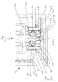
- the Fig. 2 shows a cross section through the fore-vacuum end of another vacuum pump 10.
- the vacuum pump 10 also includes a forvacuum-side part of a housing of the pump-forming body 46, and an integrally formed in the body 46 receiving space 56, for the rolling bearing 28.
- In the receiving space 56 are axial and radial damping elements 52 are provided to bias the roller bearing 28 in the receiving space.
- a separate end member 58 is provided, which bears directly against an outer ring 60 of the rolling bearing 28 and thus holds the bearing 28 in the receiving space 56.
- a spacer element 62 in particular a ring or shim, is also provided.
- the rolling bearing 28 must be clamped in a defined axial position in the receiving space 56 in order to ensure safe operation of the pump 10. Since the individual components of the vacuum pump 10 are subject to certain manufacturing tolerances, during their assembly, a spacer 62 specific to this vacuum pump 10 is selected in order to obtain the desired defined axial position of the bearing 28.
- the spacer element 62 is supported on a support surface 64 arranged on the base body 46, in particular an end face, and is arranged directly between the end element 58 and the support surface 64.
- the end member 58 is secured by means of axially extending screws 66 (see FIGS Fig. 3 ) fixed to the base 46.
- the rolling bearing 28 is thus secured by the end member 58 in the body 46.
- a securing element 48 in the form of an O-ring is provided at the lower end of the closing element 58.
- O-ring 48 presses the O-ring 48 of Fig. 2 the distribution elements 42 in the radial direction R to the outside.
- the O-ring 48 is arranged on the rolling bearing 28 opposite side of the end member 58 in a groove 68 provided therefor.
- Openings 70 which are preferably aligned with each other, are provided in the end member 58 and the bearing socket 44 so that the distribution members 42 can be biased into the bearing socket 44 to provide lubricant to the roller bearing 28, and so that the or the fixative - eg Screws 66 - can be placed on the bearing holder 44 for fixing the closing element 58.
- the terminating element 58 thus fulfills a number of functions.
- a device for fixing the position of the distribution elements 42 on the rolling bearing 28 opposite side of the closing element 58 is provided.
- it serves for clamping and axial fixing of the rolling bearing 28 in the receiving space 56.
- the closing element 62 bears against an outer ring of the rolling bearing.
- the Fig. 3 shows a further cross section through the vacuum pump 10 according to Fig. 2 , In this cross-section, no distribution elements 42 can be seen, but one of a plurality of screws 66 by means of which the closing element 58 is anchored to the base body 46 to hold the rolling bearing 28 in its axial position or to limit the receiving space 56 in an axial direction A. ,
- a spacer 62 specific to the vacuum pump 10 is selected so that the roller bearing 28 can be installed in the bearing socket 44 in a defined axial position and with the desired tolerance.
- the rolling bearing 28 of the Fig. 1 is held by means of the axial stopper 54 via a thread in its axial position.
- the axial stop 54 By movements in an operation of the vacuum pump 10 may u. U. the axial stop 54 easily rotate, whereby the axial position of the bearing 28 could be influenced.
- This is in the vacuum pump 10 according to Fig. 2 and 3 thereby avoiding that the closing element 58 is secured by means of screws 66 to the integrally formed in the base body 46 bearing holder 44, so that the rolling bearing 28 is reliably fixed between the shoulder 72 and the end member 58. That is, the set by means of the spacer 62 axial position of the rolling bearing 28 can not change.
- axial damping element 52 which is arranged between the shoulder 72 and the rolling bearing 28
- - alternatively or additionally - axial damping elements may be arranged on the opposite side of the rolling bearing 28 (not shown), for example between the rolling bearing 28 and End element 58.
- FIG. 4 shows a side view of a curved distribution element 42, which consists for example (completely or at least partially) of poroplastic.
- the curvature can be generated, for example, by bending a strand-shaped starting material. The bending may occur during the trimming of the distribution element 42.
- a curved distribution element 42 As an alternative to a curved distribution element 42, it would also be possible to provide an elastic distribution element 42 (not shown), which is suitable for the Installation is compressed and clamped in relief springs in the openings 70 and depressions of the bearing holder 44 so that it is fixed in its installed position.
- Such elastic distribution elements 42 can also with a fuse element 48 according to Fig. 2 or 3 cooperate.
- the distribution elements 42 - alternatively or additionally - are clamped in their circumferential direction U.
- they are clamped by slightly rotated relative to each other openings 70 of the bearing holder 44 and the end member in the circumferential direction U.
Landscapes
- Engineering & Computer Science (AREA)
- Mechanical Engineering (AREA)
- General Engineering & Computer Science (AREA)
- Non-Positive Displacement Air Blowers (AREA)
Abstract
Description
- Die vorliegende Erfindung betrifft eine Vakuumpumpe, insbesondere eine Turbomolekularpumpe, die ein Lager, einen einen vorvakuumseitigen Teil eines Gehäuses der Pumpe bildenden Grundkörper, einen integral in dem Grundkörper ausgebildeten Aufnahmeraum für das Lager, zumindest ein axiales Dämpfungselement, das in dem Aufnahmeraum angeordnet ist und das zum Vorspannen des Lagers in dem Aufnahmeraum vorgesehen ist, und ein separates Abschlusselement, mit dem der Aufnahmeraum abgeschlossen ist, umfasst.
- Turbomolekularpumpen weisen in der Regel mehrere pumpwirksam in Serie geschaltete Turbomolekularpumpstufen auf. Diese werden jeweils durch eine an einer Rotorwelle befestigte Rotorscheibe und eine zwischen benachbarten Rotorscheiben angeordnete und in dem Gehäuse festgelegte Statorscheibe gebildet. Zur drehbaren Lagerung der Rotorwelle sind in der Regel ein Wälzlager im Bereich eines Pumpenauslasses und ein Permanentmagnetlager im Bereich eines Pumpeneinlasses vorgesehen.
- Um ein stabiles Laufverhalten der Rotorwelle der Vakuumpumpe zu erreichen, ist die Art der Einbettung des Lagers in der Vakuumpumpe von großer Bedeutung. Insbesondere bei kleineren Turbomolekularpumpen ist das auslassseitige Lager oftmals axial und radial in Schwingringe eingebettet bzw. eingespannt. Dem Lager wird hierbei eine gewisse axiale Bewegungsfreiheit zugestanden, bis zumindest der axiale Schwingring am Lager angreift. Im Stand der Technik ist es bekannt, diese axiale Bewegungsfreiheit durch einen per Gewinde verstellbaren Axialanschlag zu erreichen. Durch den Axialanschlag wird auch das Lager in der Pumpe vorgespannt.
- Im Unterschied hierzu wird bei großen Turbomolekularpumpen das Lager in der Regel zwischen Schwingringen innerhalb einer Lagerfassung mit einer gewissen Vorspannung eingeklemmt. Die fertig eingestellte, vormontierte Lagerfassung wird danach in einer Vakuumpumpe montiert.
- Um die Einsatzmöglichkeiten von Turbomolekularpumpen flexibler gestalten zu können, werden diese zunehmend miniaturisiert, so dass weder eine vormontierte Lagerfassung noch ein per Gewinde axial einstellbarer Axialanschlag ohne weiteres integriert werden können.
- Es ist daher eine Aufgabe der vorliegenden Erfindung, eine möglichst kompakte Anordnung für ein Lager einer Vakuumpumpe zu schaffen, die eine gewisse axiale Bewegungsfreiheit eines Lagers gestattet, die das Lager axial und radial zuverlässig einspannt und die eine Verkleinerung der Vakuumpumpe bei gleicher Pumpenleistung ermöglicht. Eine weitere Aufgabe der vorliegenden Erfindung liegt darin, die Montage einer Vakuumpumpe zu vereinfachen.
- Diese Aufgaben werden durch eine Vakuumpumpe mit den Merkmalen gemäß Anspruch 1 gelöst.
- Erfindungsgemäß ist eine Vakuumpumpe, insbesondere eine Turbomolekularpumpe, vorgesehen, die ein Lager, insbesondere ein mit Schmiermittel versorgtes Lager, einen einen vorvakuumseitigen Teil eines Gehäuses der Pumpe bildenden Grundkörper, einen integral in dem Grundkörper ausgebildeten Aufnahmeraum für das Lager, zumindest ein axiales Dämpfungselement, das in dem Aufnahmeraum angeordnet ist und zum Vorspannen des Lagers in dem Aufnahmeraum vorgesehen ist, und ein separates Abschlusselement, das den Aufnahmeraum in axialer Richtung begrenzt, umfasst. Die Vakuumpumpe zeichnet sich dadurch aus, dass wenigstens ein Abstandselement, insbesondere eine Passscheibe, vorgesehen ist, um das Lager in dem Aufnahmeraum in einer definierten axialen Position einzuspannen.
- Durch das Vorsehen eines separaten Abschlusselements in Kombination mit einem Abstandselement kann für jede Vakuumpumpe die benötigte Vorspannung exakt eingestellt werden. D.h. für jede Vakuumpumpe wird aus einer Mehrzahl von unterschiedlich dimensionierten Abstandselementen jenes gewählt, durch das sich bei einer wohldefinierten axialen Lage des Abschlusselements die optimale axiale Lage des Lagers und/oder die geeignete Vorspannung einstellt. Das Abschlusselement wird dann beispielsweis einfach in den Aufnahmeraum eingebracht, bis es anschlägt, und in dieser Position fixiert. Die Lage des Anschlags ergibt sich dabei - direkt oder indirekt - aus der Ausgestaltung des Abstandselements.
- Ferner können Vakuumpumpen mit dem erfindungsgemäßen Lagerkonzept aufgrund des nicht vorhandenen verstellbaren Axialanschlags bzw. der nicht verwendeten, separaten Lagerfassung mit weniger Komponenten und insbesondere kleiner und einfacher gebaut werden. Die Konstruktion des den Aufnahmeraum bildenden Grundkörpers kann vereinfacht werden, was sich zusätzlich positiv auf die Herstellungskosten der Vakuumpumpe auswirkt. Ferner werden Verunreinigungen des Lagers durch ein zusätzliches Gewinde in dessen Nähe, nämlich das Gewinde des verstellbaren Axialanschlags, vermieden.
- Vorzugsweise ist das Lager als ein Wälzlager ausgebildet. Das Wälzlager wird in einem integral ausgebildeten Aufnahmeabschnitt des Grundkörpers, der den Aufnahmeraum bildet, eingebracht. Das Lager wird dann durch das Abschlusselement in dem Aufnahmeraum eingespannt. Beispielsweise wird das als separates Bauteil ausgebildete Abschlusselement von einem vorvakuumseitigen, stirnseitigen Ende des Grundkörpers in den Aufnahmeraum eingebracht und dort fixiert. Das axiale Dämpfungselement sorgt für eine auf das Lager wirkende, vorspannende Kraft.
- In diesem Zusammenhang ist es möglich, dass das Abstandselement vorzugsweise in oder an dem Abschlusselement vorgesehen ist. Das Abstandselement ist z.B. eine Ringscheibe, eine Passscheibe, eine Scheibe mit zumindest einem Loch. Aber auch polygonale (dreieckige, viereckige und mehreckige) Formen sind möglich, die bei entsprechender Geometrie des Aufnahmeraums automatisch verdrehsicher angeordnet sind.
- Vorzugsweise ist das Abschlusselement in Gebrauchslage in seiner axialen Position und seiner radialen Lage fixiert. Durch das Fixieren des Abschlusselements in einer axialen Position und seiner radialen Lage wird ein Verstellen zumindest der axialen Spannung vermieden. Ferner wird kein verstellbarer Axialanschlag zum Einstellen der Vorspannung benötigt.
- Bevorzugt istdas Abstandselement zwischen dem Grundkörper und dem Abschlusselement angeordnet. Durch die Dimensionierung des Abstandselements wird auf einfache Weise das Einstellen eines Abstands zwischen dem Grundkörper und dem Abschlusselement herbeigeführt, um das Lager in dem Grundkörper mit einer definierten axialen Spannung einzubetten.
- Vorzugsweise stützt sich das Abstandselement axial an einer an dem Grundkörper angeordneten Abstützfläche, insbesondere an einer Stirnfläche ab.
- Gemäß einer Ausführungsform ist das Abstandselement zwischen einem weiteren axialen Dämpfungselement und der Abstützfläche oder zwischen einem an der Abstützfläche angeordneten axialen Dämpfungselement und dem Abschlusselement angeordnet. Das Vorsehen eines weiteren axialen Dämpfungselements ermöglicht eine noch genauere Einstellung der axialen Bewegungsfreiheit, die ein Lager aufweisen darf, um im Betrieb der Vakuumpumpe die Rotorwelle zu lagern. Insbesondere ist das Abstandselement direkt zwischen der Abstützfläche und dem Abschlusselement angeordnet. D.h. bei dieser Ausführungsform sind keine Zwischenkomponenten weder zwischen dem Abstandselement und der Abstützfläche noch zwischen dem Abstandselement und dem Abschlusselement vorgesehen.
- Bevorzugt ist das z.B. als Druckring ausgebildete Abschlusselement mittels Schrauben an dem Grundkörper fixiert. Schrauben sind zuverlässige und kostengünstige Fixierungsmittel. Die Schrauben verbinden das Abschlusselement insbesondere in einer axialen Richtung mit dem Grundkörper, indem sie das Abschlusselement in axialer Richtung gegen den Grundkörper pressen.
- Eine Schraubverbindung kann entweder mit einer von außen durch das Abschlusselement geführten Schraube, die mit einem in dem Grundkörper vorgesehenen Gewinde oder einer von außen anbringbaren Mutter, die mit einem von dem Grundkörper abstehenden Gewinde kooperiert, verwendet werden. Vorzugsweise sind zwei bis sechs Schraubverbindungen vorgesehen, um das Abschlusselement an dem Grundkörper zu fixieren.
- Vorteilhafterweise weist das Abschlusselement einen Ansatz auf, mittels dem das Lager in dem Aufnahmeraum in seiner axialen Position fixiert ist, insbesondere wobei das Abschlusselement, bevorzugt über dessen Ansatz, in direktem Kontakt mit dem Lager steht.
- Beispielsweise ist der Ansatz ein ringförmiger Ansatz, sodass dieser mit einem z.B. ringförmigen Teil des Lagers kooperieren und so einen homogenen Druck auf das Lager ausüben kann.
- Bevorzugt erstreckt sich der Ansatz in axialer Richtung durch das Abstandselement hindurch. Dadurch, dass der Ansatz sich in axialer Richtung durch das Abschlusselement hindurch erstreckt, kommt das Abstandselement nicht zwingend mit dem Lager in Kontakt. Außerdem kann der Ansatz dann bei geeigneter Ausgestaltung auf einfache Weise zur einfachen und korrekten Positionierung des Abstandselements beitragen.
- Insbesondere ist die Reihenfolge der Komponenten von radial innen nach radial außen der Pumpe gesehen in der Ebene des Ansatzes: Ansatz, Abstandselement, Grundkörper.
- Vorzugsweise liegt das Abschlusselement an einem Außenring des Lagers an. Durch das direkte Anliegen des Abstandselements an dem Außenring des Lagers wird die nicht beweglich angeordnete Komponente des Lagers zum axialen Einspannen des Lagers in dem Aufnahmeraum verwendet. Insbesondere weist der den Aufnahmeraum bildende Grundkörper eine Schulter auf, die in den Aufnahmeraum hineinragt und als axialer Anschlag für das Lager dient. Insbesondere wird das Lager zwischen der Schulter und dem Abschlusselement, insbesondere dessen Ansatz in axialer Richtung fixiert bzw. eingespannt.
- Bevorzugt ist das zumindest eine axiale Dämpfungselement zwischen der Schulter und dem Lager angeordnet. Zusätzlich oder alternativ kann das bzw. ein weiteres axiales Dämpfungselement zwischen dem Lager und dem Abschlusselement angeordnet sein.
- Durch das Vorsehen des zumindest einen axialen Dämpfungselements zwischen der Schulter und dem Lager kann das Lager derart im Aufnahmeraums angeordnet sein, dass das Lager mit möglichst wenig Spiel in dem Aufnahmeraum aufgenommen ist. Vorzugsweise liegt das Dämpfungselement bzw. liegen die Dämpfungselemente direkt an dem Lager an.
- Insbesondere sind in dem Abschlusselement und/oder dem Grundkörper Öffnungen vorgesehen und das Abstandselement weist mit den Öffnungen fluchtende
- Durchbrüche auf, um das Lager mit Schmiermittel versorgen und/oder Fixierungsmittel zur Fixierung des Abschlusselements an dem Grundkörper einzubringen zu können. Vorzugsweise sind 6 bis 12 solcher Durchbrüche bzw. Öffnungen vorgesehen.
- Die Öffnungen und die Durchbrüche sind relativ zueinander ausgerichtet. Beispielsweise entspricht die Anzahl der Durchbrüche in dem Abstandselement der der Anzahl der Öffnungen sowie der Fixierungsmittel. Die Fixierungsmittel sind insbesondere Schraubverbindungen, die durch die Durchbrüche bzw. Öffnungen in dem Abstandselement bzw. dem Abschlusselement geführt sind. Bevorzugt sind jedoch zusätzliche Öffnungen und Durchbrüche für Schmiermittel fördernde Verteilungselemente vorgesehen. Durch die Verteilungselemente wird ein beständiger Ölausgleich und damit eine zuverlässige beidseitige Schmierung des Lagers der Vakuumpumpe sichergestellt. Die Verteilungselemente können beispielsweise Stäbchen aus Poroplastmaterial sein. Beispielsweise sind sie in Bohrungen, die in dem Grundkörper der Vakuumpumpe vorgesehen sind, angeordnet. Die Bohrungen sind bevorzugt separat von dem Aufnahmeraum angeordnet. Insbesondere ist zusätzlich zumindest eine Einrichtung vorgesehen, um die Schmiermittel fördernden Verteilungselemente zumindest axial zu sichern.
- Vorzugsweise ist/sind das Abstandselement und gegebenenfalls ein axiales Dämpfungselement in das Abschlusselement integriert. Hierdurch kann eine integrale Einheit bereitgestellt werden, um das Lager axial in dem Aufnahmeraum zu verspannen.
- Weitere Ausführungsformen der erfindungsgemäßen Vakuumpumpe sind in den Ansprüchen, der Beschreibung und den beigefügten Zeichnungen angegeben. Die Erfindung wird nachstehend auch hinsichtlich weiterer Vorteile und Merkmale unter Bezugnahme auf die beigefügten Zeichnungen anhand von Ausführungsbeispielen erläutert. Es zeigen:
- Fig. 1
- eine Vakuumpumpe in einem Querschnitt,
- Fig. 2
- einen Querschnitt durch ein vorvakuumseitiges Ende einer erfindungsgemäßen Vakuumpumpe,
- Fig. 3
- einen weiterer Querschnitt durch die Vakuumpumpe gemäß
Fig. 2 und - Fig. 4
- ein erfindungsgemäßes Verteilungselement.
- Die in
Fig. 1 gezeigte Vakuumpumpe 10 umfasst einen von einem Einlassflansch 12 umgebenden Pumpeneinlass 14 und einen Pumpenauslass, sowie mehrere Prozessgaspumpstufen zur Förderung des an dem Pumpeneinlass anstehenden Prozessgases zu dem Pumpenauslass. Mit dem Bezugszeichen 16 ist ein Bauraum für elektrische Anschlüsse bezeichnet. Die Vakuumpumpe 10 umfasst ein Gehäuse 18 und einen in dem Gehäuse 18 angeordneten Rotor mit einer um die Rotationsachse drehbar gelagerten Rotorwelle 20. - Die gezeigte Vakuumpumpe 10 ist als Turbomolekularpumpe ausgebildet und umfasst mehrere pumpwirksam miteinander in Serie geschaltete Turbomolekularpumpstufen mit mehreren an der Rotorwelle 20 befestigten radialen Rotorscheiben 22 und zwischen den Rotorscheiben 22 angeordneten und in dem Gehäuse 18 festgelegten Statorscheiben 24, wobei eine Rotorscheibe 22 und eine benachbarte Statorscheibe 24 jeweils eine turbomolekulare Pumpstufe bilden. Die Statorscheiben 24 sind durch Abstandsringe 26 in einem gewünschten axialen Abstand zueinander gehalten. Zur drehbaren Lagerung der Rotorwelle 20 sind ein Wälzlager 28 im Bereich des Pumpenauslasses und ein Permanentmagnetlager 30 im Bereich des Pumpeneinlasses 14 vorgesehen. Im Bereich des Wälzlagers 28 ist an der Rotorwelle 20 eine konische Spritzmutter 32 mit einem zu dem Wälzlager 28 hin zunehmenden Außendurchmesser vorgesehen. Die Spritzmutter 32 steht mit zumindest einem Abstreifer eines Betriebsmittelspeichers in gleitendem Kontakt. Der Betriebsmittelspeicher umfasst mehrere aufeinander gestapelte saugfähige Scheiben 34 aus einem Filzmaterial (Speicher- und/oder Zufuhrkomponenten), die mit einem Betriebsmittel für das Wälzlager 28, zum Beispiel mit einem Schmiermittel, insbesondere mit Öl, getränkt sind.
- Bei Betrieb der Vakuumpumpe 10 wird das Betriebsmittel durch kapillare Wirkung von dem Betriebsmittelspeicher über den Abstreifer auf die rotierende Spritzmutter 32 übertragen und infolge der Zentrifugalkraft entlang der Spritzmutter 32 in Richtung des größer werdenden Außendurchmessers der Spritzmutter 32 zum Wälzlager 28 hin gefördert. Das Wälzlager 28 und der Betriebsmittelspeicher sind durch einen wannenförmigen Einsatz 36 und ein Deckelelement 38 der Vakuumpumpe 10 eingefasst.
- Um die Schmierung des Wälzlagers 28 zu gewährleisten, sind auch am oberen Ende des Wälzlagers 28 saugfähige Scheiben 40 angeordnet. Diese sind mittels Verteilungselemente 42, z.B. Poroplast-Stäbe, mit den untenliegenden, aufeinander gestapelten saugfähigen Scheiben 34 verbunden. Die Verteilungselemente 42 gewährleisten mittels Kapillarwirkung einen Austausch des Schmiermittels zwischen den saugfähigen Scheiben 34, 40 und ermöglichen so eine allseitige Schmierung des Wälzlagers 28.
- Das Wälzlager 28 und die Verteilungselemente 42 sind in einer Lagerfassung 44 angeordnet. Im vorliegenden Beispiel ist die Lagerfassung 44 in einem einen vorvakuumseitigen Teil des Gehäuses 18 der Vakuumpumpe bildenden Grundkörper 46 angeordnet. Um zu verhindern, dass die Verteilungselemente 42 herausfallen, wenn das Deckelelement 38 und die Scheiben 34 zu Wartungszwecken entfernt werden, ist ein Sicherungselement 48 in der Form eines O-Rings in einer Nut in einer innen liegenden Wand 50 des wannenförmigen Einsatzes 36 angeordnet. Der O-Ring 48 drückt die Verteilungselemente 42 in deren in
Fig. 1 unteren Bereich radial nach innen (Richtung R) und sichert diese mittels eines Reibschlusses in Ihrer Einbaulage. - Es ist auch möglich, an jedem Verteilungselement 42 einen eigenen O-Ring 48 vorzusehen. Der O-Ring 48 würde auch dann das Verteilungselement 42 von der innenliegenden Wand 50 des Grundkörpers 46 radial nach innen drücken. Somit wären die einzelnen Verteilungselemente 42 jeweils unabhängig voneinander in ihrer Einbaulage fixiert, um ihr Herausfallen zu verhindern.
- Um das Wälzlager 28 in seiner Lage zu sichern, sind radiale und axiale Dämpfungselemente 52 in einem Aufnahmeraum 56 für das Wälzlager 28 vorgesehen. Das Wälzlager 28 wird in diesem Aufnahmeraum 56 mittels eines per Gewinde einstellbaren Axialanschlags 54 derart vorgespannt, dass es eine bedarfsgerechte, geringfügige axiale Bewegungsfreiheit in der axialen Richtung A besitzt.
- Die
Fig. 2 zeigt einen Querschnitt durch das vorvakuumseitige Ende einer weiteren Vakuumpumpe 10. Die Vakuumpumpe 10 umfasst ebenfalls einen einen vorvakuumseitigen Teil eines Gehäuses der Pumpe bildenden Grundkörper 46, sowie einen integral in dem Grundkörper 46 ausgebildeten Aufnahmeraum 56, für das Wälzlager 28. In dem Aufnahmeraum 56 sind axiale und radiale Dämpfungselemente 52 vorgesehen, um das Wälzlager 28 in dem Aufnahmeraum vorzuspannen. Um die Lage des Wälzlagers 28 in axialer Richtung A nach unten zu begrenzen, ist ein separates Abschlusselement 58 vorgesehen, welches direkt an einem Außenring 60 des Wälzlagers 28 anliegt und damit das Lager 28 in dem Aufnahmeraum 56 hält. - Zwischen dem Grundkörper 46 und dem Abschlusselement 58 ist ferner ein Abstandselement 62, insbesondere eine Ring- oder Passscheibe, vorgesehen. Beim Zusammenbau einer Vakuumpumpe 10 muss das Wälzlager 28 in einer definierten axialen Position in dem Aufnahmeraum 56 eingespannt werden, um einen sicheren Betrieb der Pumpe 10 zu gewährleisten. Da die einzelnen Bauteile der Vakuumpumpe 10 gewissen Fertigungstoleranzen unterliegen, wird bei ihrem Zusammenbau ein für diese Vakuumpumpe 10 spezifisches Abstandselement 62 ausgewählt, um die gewünschte definierte axiale Position des Lagers 28 zu erhalten.
- Das Abstandselement 62 stützt sich an einer an dem Grundkörper 46 angeordneten Abstützfläche 64, insbesondere einer Stirnfläche, ab und ist unmittelbar zwischen dem Abschlusselement 58 und der Abstützfläche 64 angeordnet. Das Abschlusselement 58 ist mittels sich in axialer Richtung erstreckenden Schrauben 66 (siehe
Fig. 3 ) an dem Grundkörper 46 fixiert. Letztlich wird das Wälzlager 28 somit durch das Abschlusselement 58 in dem Grundkörper 46 gesichert. Mit Hilfe einer aus einem Satz verschieden dimensionierter Passscheiben, d.h. Passscheiben mit unterschiedlicher Dicke, gewählten Passscheibe 62 wird die optimale axiale Lage des Wälzlagers 28 eingestellt. - Zur Schmierung des Wälzlagers 28 sind mehrere Verteilungselemente 42, in
Figur 2 sind zwei erkennbar, in Öffnungen 70 bzw. Vertiefungen der Lagerfassung 44 vorgesehen. Um die Verteilungselemente 42 in ihrer Einbaulage mit Kraft zu beaufschlagen bzw. vorzuspannen und mittels Reibschluss zu fixieren, ist am unteren Ende des Abschlusselements 58 ein Sicherungselement 48 in der Form eines O-Rings vorgesehen. Im Gegensatz zu dem inFig. 1 gezeigten O-Ring 48 drückt der O-Ring 48 derFig. 2 die Verteilungselemente 42 in radialer Richtung R nach außen. Der O-Ring 48 ist auf der dem Wälzlager 28 gegenüberliegenden Seite des Abschlusselements 58 in einer dafür vorgesehenen Nut 68 angeordnet. - In dem Abschlusselement 58 und in der Lagerfassung 44 sind jeweils Öffnungen 70 vorgesehen, die vorzugsweise so miteinander fluchten, so dass die Verteilungselemente 42 mit Vorspannung in der Lagerfassung 44 angeordnet werden können, um das Wälzlager 28 mit Schmiermittel zu versorgen, und so dass das oder die Fixierungsmittel - z.B. Schrauben 66 - zur Fixierung des Abschlusselements 58 an der Lagerfassung 44 platziert werden können.
- Das Abschlusselement 58 erfüllt somit mehrere Funktionen. Zum einen wird mittels des O-Rings 48 eine Einrichtung zur Lagefixierung der Verteilungselemente 42 an der dem Wälzlager 28 gegenüberliegenden Seite des Abschlusselements 58 bereitgestellt. Zum anderen dient es zum Einspannen und axialen Festlegen des Wälzlagers 28 in dem Aufnahmeraum 56. Hierbei liegt das Abschlusselement 62 an einem Außenring des Wälzlagers an.
- Die
Fig. 3 zeigt einen weiteren Querschnitt durch die Vakuumpumpe 10 gemäßFig. 2 . In diesem Querschnitt sind keine Verteilungselemente 42 zu sehen, sondern eine von mehreren Schrauben 66 mittels derer das Abschlusselement 58 an dem Grundkörper 46 verankert ist, um das Wälzlager 28 in seiner axialen Lage zu halten bzw. den Aufnahmeraum 56 in einer axialen Richtung A zu begrenzen. - In der Zeichnung gemäß
Fig. 3 ist eine in den Aufnahmeraum 56 ragende Schulter 72 zu sehen, die am Grundkörper 46 ausgebildet ist. Das Wälzlager 28 ist zwischen der Schulter 72 und einem Ansatz 74 des Abschlusselements 58 angeordnet, wobei sich der Ansatz 74 in axialer Richtung durch das Abstandselement 62 hindurch erstreckt. Das Abstandselement 62 liegt wiederum an einem Ringflansch 76 des Abschlusselements 58 an. An der dem Ansatz 74 abgewandten Seite des Flansches 76 ist der Abschnitt des Abschlusselements 58 angeordnet, der die Nut 68 für den O-Ring 48 trägt. - Beim Zusammenbau der Vakuumpumpe 10 wird ein für die Vakuumpumpe 10 spezifisches Abstandselement 62 ausgewählt, so dass das Wälzlager 28 in einer definierten axialen Lage und mit der gewünschten Toleranz in der Lagerfassung 44 eingebaut werden kann. Das Wälzlager 28 der
Fig. 1 ist mittels des Axialanschlags 54 über ein Gewinde in seiner axialen Lage gehalten. Durch Bewegungen bei einem Betrieb der Vakuumpumpe 10 kann sich u. U. der Axialanschlag 54 leicht drehen, wodurch auch die axiale Lage des Lagers 28 beeinflusst werden könnte. Dies wird bei der Vakuumpumpe 10 gemäßFig. 2 und3 dadurch vermieden, dass das Abschlusselement 58 mittels Schrauben 66 an der integral im Grundkörper 46 ausgeformten Lagerfassung 44 gesichert wird, so dass das Wälzlager 28 zuverlässig zwischen der Schulter 72 und dem Abschlusselement 58 fixiert ist. D.h. die mittels des Abstandselements 62 eingestellte axiale Lage des Wälzlagers 28 kann sich nicht verändern. - Zusätzlich zu dem oberen axialen Dämpfungselement 52, welches zwischen der Schulter 72 und dem Wälzlager 28 angeordnet ist, können - alternativ oder zusätzlich - axiale Dämpfungselemente auf der gegenüberliegenden Seite des Wälzlagers 28 angeordnet sein (nicht gezeigt), zum Beispiel zwischen dem Wälzlager 28 und dem Abschlusselement 58.
- Die
Figur 4 zeigt eine Seitenansicht eines gekrümmten Verteilungselements 42, das zum Beispiel (vollständig oder zumindest teilweise) aus Poroplast besteht. Die Krümmung kann z.B. durch Biegen eines strangförmigen Ausgangsmaterials erzeugt werden. Das Biegen kann während dem Zuschneiden des Verteilungselements 42 erfolgen. Beim Einführen des gekrümmten Verteilungselements 42 in die Öffnung 70 in der Lagerfassung 44 bzw. in dem Grundkörper 46 wird dieses so verspannt, dass ein Herausfallen des Verteilungselements 42 verhindert wird. - Als Alternative zu einem gekrümmten Verteilungselement 42 könnte auch ein elastisches Verteilungselement 42 vorgesehen sein (nicht gezeigt), das für den Einbau zusammengedrückt wird und das sich bei Entlastung federartig in den Öffnungen 70 bzw. Vertiefungen der Lagerfassung 44 verspannt, so dass es in seiner Einbaulage fixiert wird. Solche elastischen Verteilungselemente 42 können auch mit einem Sicherungselement 48 gemäß
Fig. 2 oder3 kooperieren. - Es wäre auch denkbar, dass die Verteilungselemente 42 - alternativ oder zusätzlich - in ihrer Umfangsrichtung U verspannt werden. Beispielsweise werden sie durch leicht relativ zueinander verdrehte Öffnungen 70 der Lagerfassung 44 bzw. des Abschlusselements in Umfangsrichtung U eingeklemmt.
-
- 10
- Vakuumpumpe
- 12
- Einlassflansch
- 14
- Pumpeneinlass
- 16
- Bauraum
- 18
- Gehäuse
- 20
- Rotorwelle
- 22
- Rotorscheibe
- 24
- Statorscheibe
- 26
- Abstandsring
- 28
- Wälzlager
- 30
- Permanentmagnetlager
- 32
- Spritzmutter
- 34, 40
- saugfähige Scheiben
- 36
- wannenförmiger Einsatz
- 38
- Deckelelement
- 42
- Verteilungselement
- 44
- Lagerfassung
- 46
- Grundkörper
- 48
- Sicherungselement
- 50
- innenliegende Wand
- 52
- Dämpfungselement
- 54
- Axialanschlag
- 56
- Aufnahmeraum
- 58
- Abschlusselement
- 60
- Außenring
- 62
- Abstandselement
- 64
- Abstützfläche
- 66
- Schraube
- 68
- Nut
- 70
- Öffnung
- 72
- Schulter
- 74
- Ansatz
- 76
- Ringflansch
- A
- axiale Richtung
- R
- radiale Richtung
- U
- Umfangsrichtung
Claims (15)
- Vakuumpumpe, insbesondere eine Turbomolekularpumpe, die ein Lager (28), einen ein vorvakuumseitigen Teil eines Gehäuses der Pumpe (10) bildenden Grundkörper (46), einen integral in dem Grundkörper ausgebildeten Aufnahmeraum (56) für das Lager, zumindest ein axiales Dämpfungselement (52), das in dem Aufnahmeraum angeordnet ist und das zum Vorspannen des Lagers (28) in dem Aufnahmeraum vorgesehen ist, und ein separates Abschlusselement (58), das den Aufnahmeraum in axialer Richtung begrenzt, umfasst,
wobei wenigstens ein Abstandselement (62), insbesondere eine Passscheibe, vorgesehen ist, um das Lager (28) in dem Aufnahmeraum (56) in einer definierten axialen Position einzuspannen. - Vakuumpumpe nach Anspruch 1,
dadurch gekennzeichnet, dass das Abschlusselement (58) in Gebrauchslage in seiner axialen Position und seiner radialen Lage fixiert ist. - Vakuumpumpe nach Anspruch 1 oder 2,
dadurch gekennzeichnet, dass das Abstandselement (62) zwischen dem Grundkörper (46) und dem Abschlusselement (58) angeordnet ist. - Vakuumpumpe nach zumindest einem der vorstehenden Ansprüche, dadurch gekennzeichnet, dass sich das Abstandselement (62) axial an einer an dem Grundkörper angeordneten Abstützfläche (64), insbesondere einer Stirnfläche, abstützt.
- Vakuumpumpe nach Anspruch 4,
dadurch gekennzeichnet, dass das Abstandselement (62) zwischen einem weiteren axialen Dämpfungselement und der Abstützfläche (64) oder zwischen einem an der Abstützfläche angeordneten axialen Dämpfungselement und dem Abschlusselement angeordnet ist. - Vakuumpumpe nach Anspruch 4,
dadurch gekennzeichnet, dass das Abstandselement (62) direkt zwischen der Abstützfläche (64) und dem Abschlusselement (58) angeordnet ist. - Vakuumpumpe nach zumindest einem der vorstehenden Ansprüche,
dadurch gekennzeichnet, dass das insbesondere als Druckring ausgebildete Abschlusselement (58) mittels Schrauben (66) an dem Grundkörper (46) fixiert ist, insbesondere wobei die Schrauben den Druckring in axialer Richtung mit dem Grundkörper verbinden. - Vakuumpumpe nach Anspruch 7,
dadurch gekennzeichnet, dass das Abschlusselement (58) einen Ansatz (74) aufweist, mittels dem das Lager (28) in dem Aufnahmeraum (56) in seiner axialen Position fixiert ist, insbesondere wobei das Abschlusselement in direktem Kontakt mit dem Lager (28) steht. - Vakuumpumpe nach Anspruch 8,
dadurch gekennzeichnet, dass sich der Ansatz (74) in axialer Richtung durch das Abstandselement (62) hindurch erstreckt. - Vakuumpumpe nach Anspruch 8 oder 9,
dadurch gekennzeichnet, dass das Abschlusselement (58) an einem Außenring (60) des Lagers (28) anliegt. - Vakuumpumpe nach zumindest einem der vorstehenden Ansprüche,
dadurch gekennzeichnet, dass der Grundkörper (46) eine in den Aufnahmeraum (56) ragende Schulter (72) aufweist, wobei das Lager (28) axial zwischen der Schulter und dem Abschlusselement (58) angeordnet, vorzugsweise eingespannt, ist. - Vakuumpumpe nach Anspruch 11,
dadurch gekennzeichnet, dass das zumindest eine axiale Dämpfungselement (52) zwischen der Schulter (72) und dem Lager (28) angeordnet ist, insbesondere wobei ein weiteres axiales Dämpfungselement auf der dem zumindest einen axialen Dämpfungselement gegenüberliegenden Seite des Lagers zwischen dem Lager und dem Abschlusselement (58) angeordnet ist. - Vakuumpumpe nach zumindest einem der vorstehenden Ansprüche,
dadurch gekennzeichnet, dass in dem Abschlusselement (58) und/oder dem Grundkörper (46) Öffnungen (70) vorgesehen sind und dass das Abstandselement (62) mit den Öffnungen fluchtende Durchbrüche aufweist, um das Lager mit Schmiermittel zu versorgen und/oder Fixierungsmittel zur Fixierung des Abschlusselements an dem Grundkörper einzubringen. - Vakuumpumpe nach Anspruch 13,
dadurch gekennzeichnet, dass Schmiermittel fördernde Verteilungselemente (42) durch die Öffnungen (70) bzw. Durchbrüche hindurch geführt sind, insbesondere wobei die Schmiermittel fördernden Verteilungselemente (42) in Vertiefungen des Grundkörpers aufnehmbar sind. - Vakuumpumpe nach zumindest einem der vorstehenden Ansprüche,
dadurch gekennzeichnet, dass das Abstandselement (62) und gegebenenfalls ein axiales Dämpfungselement in dem Abschlusselement (58) integriert ist/sind.
Priority Applications (1)
| Application Number | Priority Date | Filing Date | Title |
|---|---|---|---|
| EP15172540.5A EP3106675B1 (de) | 2015-06-17 | 2015-06-17 | Vakuumpumpe |
Applications Claiming Priority (1)
| Application Number | Priority Date | Filing Date | Title |
|---|---|---|---|
| EP15172540.5A EP3106675B1 (de) | 2015-06-17 | 2015-06-17 | Vakuumpumpe |
Publications (2)
| Publication Number | Publication Date |
|---|---|
| EP3106675A1 true EP3106675A1 (de) | 2016-12-21 |
| EP3106675B1 EP3106675B1 (de) | 2020-01-15 |
Family
ID=53404452
Family Applications (1)
| Application Number | Title | Priority Date | Filing Date |
|---|---|---|---|
| EP15172540.5A Active EP3106675B1 (de) | 2015-06-17 | 2015-06-17 | Vakuumpumpe |
Country Status (1)
| Country | Link |
|---|---|
| EP (1) | EP3106675B1 (de) |
Citations (3)
| Publication number | Priority date | Publication date | Assignee | Title |
|---|---|---|---|---|
| US20050169783A1 (en) * | 2004-01-30 | 2005-08-04 | Itt Manufacturing Enterprises, Inc. | Impeller adjustment device and method for doing the same for close coupled pumps |
| EP1921322A2 (de) * | 2006-11-11 | 2008-05-14 | Pfeiffer Vacuum GmbH | Lagermodul für eine Vakuumpumpe |
| US20130121858A1 (en) * | 2011-11-15 | 2013-05-16 | Yukiteru Sekita | Vacuum pump |
-
2015
- 2015-06-17 EP EP15172540.5A patent/EP3106675B1/de active Active
Patent Citations (3)
| Publication number | Priority date | Publication date | Assignee | Title |
|---|---|---|---|---|
| US20050169783A1 (en) * | 2004-01-30 | 2005-08-04 | Itt Manufacturing Enterprises, Inc. | Impeller adjustment device and method for doing the same for close coupled pumps |
| EP1921322A2 (de) * | 2006-11-11 | 2008-05-14 | Pfeiffer Vacuum GmbH | Lagermodul für eine Vakuumpumpe |
| US20130121858A1 (en) * | 2011-11-15 | 2013-05-16 | Yukiteru Sekita | Vacuum pump |
Also Published As
| Publication number | Publication date |
|---|---|
| EP3106675B1 (de) | 2020-01-15 |
Similar Documents
| Publication | Publication Date | Title |
|---|---|---|
| DE102016205057A1 (de) | Dichtungsanordnung, Bausatz für eine Dichtungsanordnung und Verfahren zur Herstellung einer Dichtungsanordnung | |
| EP2463538B1 (de) | Schrumpfscheibe zur reibschlüssigen Verbindung von rotierenden Maschinenteilen | |
| WO2015144320A1 (de) | Kühlhülse für ein lager und lager mit kühlhülse | |
| DE102009017700A1 (de) | Fluiddynamisches Lagersystem und Spindelmotor mit einem solchen Lagersystem | |
| EP3106691B1 (de) | Lagerfassung, verteilungselement und vakuumpume | |
| EP3239575A1 (de) | Käfigbaugruppe mit drosselringen | |
| EP3273077A1 (de) | Wälzlager mit montageflansch | |
| DE102008002288A1 (de) | Halteflansch für elektrische Maschine | |
| EP1193433B1 (de) | Elektromagnetisches Fluidventil | |
| EP3106675B1 (de) | Vakuumpumpe | |
| EP3730802B1 (de) | Flanschelement | |
| DE102017110017A1 (de) | Vorrichtung und Verfahren zur zentrierten Befestigung zwischen Welle und Nabe | |
| DE102010007278A1 (de) | Wälzlager und Wälzlageranordnung | |
| DE20011947U1 (de) | Lageranordnung | |
| EP3617523A1 (de) | Vakuumgerät und vakuumsystem | |
| EP3561307B1 (de) | Vakuumpumpe mit einem einlassflansch und einem lagerträger im einlass | |
| DE102014116449B4 (de) | Pumpe mit einem Lagerträger, einer Zwischenlaterne und einer Verstelleinrichtung | |
| EP3597926A1 (de) | Vakuumpumpe | |
| WO2018001811A1 (de) | Vakuumpumpe | |
| EP3084268A1 (de) | Axiale fixierung einer planetenlagerung | |
| DE102018126425A1 (de) | Nabenanordnung mit axial fluchtenden Verbindungsöffnungen | |
| DE102011116703A1 (de) | "Motorisch angetriebene Werkzeugmaschineneinheit" | |
| DE202018101223U1 (de) | Gehäuse für eine Kreiselpumpe, Kreiselpumpe mit Gehäuse und Abfüllanlage umfassend eine solche Kreiselpumpe | |
| DE102018128385B4 (de) | Sensorgehäuse | |
| DE102024209991A1 (de) | Axiale Fluidlagerstelle und Verfahren zum Montieren zweier Axialfolienlageranordnungen |
Legal Events
| Date | Code | Title | Description |
|---|---|---|---|
| PUAI | Public reference made under article 153(3) epc to a published international application that has entered the european phase |
Free format text: ORIGINAL CODE: 0009012 |
|
| STAA | Information on the status of an ep patent application or granted ep patent |
Free format text: STATUS: THE APPLICATION HAS BEEN PUBLISHED |
|
| AK | Designated contracting states |
Kind code of ref document: A1 Designated state(s): AL AT BE BG CH CY CZ DE DK EE ES FI FR GB GR HR HU IE IS IT LI LT LU LV MC MK MT NL NO PL PT RO RS SE SI SK SM TR |
|
| AX | Request for extension of the european patent |
Extension state: BA ME |
|
| STAA | Information on the status of an ep patent application or granted ep patent |
Free format text: STATUS: REQUEST FOR EXAMINATION WAS MADE |
|
| 17P | Request for examination filed |
Effective date: 20170524 |
|
| RBV | Designated contracting states (corrected) |
Designated state(s): AL AT BE BG CH CY CZ DE DK EE ES FI FR GB GR HR HU IE IS IT LI LT LU LV MC MK MT NL NO PL PT RO RS SE SI SK SM TR |
|
| GRAP | Despatch of communication of intention to grant a patent |
Free format text: ORIGINAL CODE: EPIDOSNIGR1 |
|
| STAA | Information on the status of an ep patent application or granted ep patent |
Free format text: STATUS: GRANT OF PATENT IS INTENDED |
|
| INTG | Intention to grant announced |
Effective date: 20190813 |
|
| GRAS | Grant fee paid |
Free format text: ORIGINAL CODE: EPIDOSNIGR3 |
|
| GRAA | (expected) grant |
Free format text: ORIGINAL CODE: 0009210 |
|
| STAA | Information on the status of an ep patent application or granted ep patent |
Free format text: STATUS: THE PATENT HAS BEEN GRANTED |
|
| AK | Designated contracting states |
Kind code of ref document: B1 Designated state(s): AL AT BE BG CH CY CZ DE DK EE ES FI FR GB GR HR HU IE IS IT LI LT LU LV MC MK MT NL NO PL PT RO RS SE SI SK SM TR |
|
| REG | Reference to a national code |
Ref country code: CH Ref legal event code: EP Ref country code: GB Ref legal event code: FG4D Free format text: NOT ENGLISH |
|
| REG | Reference to a national code |
Ref country code: IE Ref legal event code: FG4D Free format text: LANGUAGE OF EP DOCUMENT: GERMAN |
|
| REG | Reference to a national code |
Ref country code: DE Ref legal event code: R096 Ref document number: 502015011508 Country of ref document: DE |
|
| REG | Reference to a national code |
Ref country code: AT Ref legal event code: REF Ref document number: 1225384 Country of ref document: AT Kind code of ref document: T Effective date: 20200215 |
|
| REG | Reference to a national code |
Ref country code: NL Ref legal event code: MP Effective date: 20200115 |
|
| REG | Reference to a national code |
Ref country code: LT Ref legal event code: MG4D |
|
| PG25 | Lapsed in a contracting state [announced via postgrant information from national office to epo] |
Ref country code: RS Free format text: LAPSE BECAUSE OF FAILURE TO SUBMIT A TRANSLATION OF THE DESCRIPTION OR TO PAY THE FEE WITHIN THE PRESCRIBED TIME-LIMIT Effective date: 20200115 Ref country code: NL Free format text: LAPSE BECAUSE OF FAILURE TO SUBMIT A TRANSLATION OF THE DESCRIPTION OR TO PAY THE FEE WITHIN THE PRESCRIBED TIME-LIMIT Effective date: 20200115 Ref country code: PT Free format text: LAPSE BECAUSE OF FAILURE TO SUBMIT A TRANSLATION OF THE DESCRIPTION OR TO PAY THE FEE WITHIN THE PRESCRIBED TIME-LIMIT Effective date: 20200607 Ref country code: FI Free format text: LAPSE BECAUSE OF FAILURE TO SUBMIT A TRANSLATION OF THE DESCRIPTION OR TO PAY THE FEE WITHIN THE PRESCRIBED TIME-LIMIT Effective date: 20200115 Ref country code: NO Free format text: LAPSE BECAUSE OF FAILURE TO SUBMIT A TRANSLATION OF THE DESCRIPTION OR TO PAY THE FEE WITHIN THE PRESCRIBED TIME-LIMIT Effective date: 20200415 |
|
| PG25 | Lapsed in a contracting state [announced via postgrant information from national office to epo] |
Ref country code: HR Free format text: LAPSE BECAUSE OF FAILURE TO SUBMIT A TRANSLATION OF THE DESCRIPTION OR TO PAY THE FEE WITHIN THE PRESCRIBED TIME-LIMIT Effective date: 20200115 Ref country code: BG Free format text: LAPSE BECAUSE OF FAILURE TO SUBMIT A TRANSLATION OF THE DESCRIPTION OR TO PAY THE FEE WITHIN THE PRESCRIBED TIME-LIMIT Effective date: 20200415 Ref country code: GR Free format text: LAPSE BECAUSE OF FAILURE TO SUBMIT A TRANSLATION OF THE DESCRIPTION OR TO PAY THE FEE WITHIN THE PRESCRIBED TIME-LIMIT Effective date: 20200416 Ref country code: IS Free format text: LAPSE BECAUSE OF FAILURE TO SUBMIT A TRANSLATION OF THE DESCRIPTION OR TO PAY THE FEE WITHIN THE PRESCRIBED TIME-LIMIT Effective date: 20200515 Ref country code: SE Free format text: LAPSE BECAUSE OF FAILURE TO SUBMIT A TRANSLATION OF THE DESCRIPTION OR TO PAY THE FEE WITHIN THE PRESCRIBED TIME-LIMIT Effective date: 20200115 Ref country code: LV Free format text: LAPSE BECAUSE OF FAILURE TO SUBMIT A TRANSLATION OF THE DESCRIPTION OR TO PAY THE FEE WITHIN THE PRESCRIBED TIME-LIMIT Effective date: 20200115 |
|
| REG | Reference to a national code |
Ref country code: DE Ref legal event code: R097 Ref document number: 502015011508 Country of ref document: DE |
|
| PG25 | Lapsed in a contracting state [announced via postgrant information from national office to epo] |
Ref country code: SK Free format text: LAPSE BECAUSE OF FAILURE TO SUBMIT A TRANSLATION OF THE DESCRIPTION OR TO PAY THE FEE WITHIN THE PRESCRIBED TIME-LIMIT Effective date: 20200115 Ref country code: RO Free format text: LAPSE BECAUSE OF FAILURE TO SUBMIT A TRANSLATION OF THE DESCRIPTION OR TO PAY THE FEE WITHIN THE PRESCRIBED TIME-LIMIT Effective date: 20200115 Ref country code: SM Free format text: LAPSE BECAUSE OF FAILURE TO SUBMIT A TRANSLATION OF THE DESCRIPTION OR TO PAY THE FEE WITHIN THE PRESCRIBED TIME-LIMIT Effective date: 20200115 Ref country code: EE Free format text: LAPSE BECAUSE OF FAILURE TO SUBMIT A TRANSLATION OF THE DESCRIPTION OR TO PAY THE FEE WITHIN THE PRESCRIBED TIME-LIMIT Effective date: 20200115 Ref country code: DK Free format text: LAPSE BECAUSE OF FAILURE TO SUBMIT A TRANSLATION OF THE DESCRIPTION OR TO PAY THE FEE WITHIN THE PRESCRIBED TIME-LIMIT Effective date: 20200115 Ref country code: ES Free format text: LAPSE BECAUSE OF FAILURE TO SUBMIT A TRANSLATION OF THE DESCRIPTION OR TO PAY THE FEE WITHIN THE PRESCRIBED TIME-LIMIT Effective date: 20200115 Ref country code: LT Free format text: LAPSE BECAUSE OF FAILURE TO SUBMIT A TRANSLATION OF THE DESCRIPTION OR TO PAY THE FEE WITHIN THE PRESCRIBED TIME-LIMIT Effective date: 20200115 |
|
| PLBE | No opposition filed within time limit |
Free format text: ORIGINAL CODE: 0009261 |
|
| STAA | Information on the status of an ep patent application or granted ep patent |
Free format text: STATUS: NO OPPOSITION FILED WITHIN TIME LIMIT |
|
| 26N | No opposition filed |
Effective date: 20201016 |
|
| PG25 | Lapsed in a contracting state [announced via postgrant information from national office to epo] |
Ref country code: MC Free format text: LAPSE BECAUSE OF FAILURE TO SUBMIT A TRANSLATION OF THE DESCRIPTION OR TO PAY THE FEE WITHIN THE PRESCRIBED TIME-LIMIT Effective date: 20200115 |
|
| REG | Reference to a national code |
Ref country code: CH Ref legal event code: PL |
|
| PG25 | Lapsed in a contracting state [announced via postgrant information from national office to epo] |
Ref country code: PL Free format text: LAPSE BECAUSE OF FAILURE TO SUBMIT A TRANSLATION OF THE DESCRIPTION OR TO PAY THE FEE WITHIN THE PRESCRIBED TIME-LIMIT Effective date: 20200115 Ref country code: SI Free format text: LAPSE BECAUSE OF FAILURE TO SUBMIT A TRANSLATION OF THE DESCRIPTION OR TO PAY THE FEE WITHIN THE PRESCRIBED TIME-LIMIT Effective date: 20200115 |
|
| PG25 | Lapsed in a contracting state [announced via postgrant information from national office to epo] |
Ref country code: LU Free format text: LAPSE BECAUSE OF NON-PAYMENT OF DUE FEES Effective date: 20200617 |
|
| REG | Reference to a national code |
Ref country code: BE Ref legal event code: MM Effective date: 20200630 |
|
| PG25 | Lapsed in a contracting state [announced via postgrant information from national office to epo] |
Ref country code: CH Free format text: LAPSE BECAUSE OF NON-PAYMENT OF DUE FEES Effective date: 20200630 Ref country code: IE Free format text: LAPSE BECAUSE OF NON-PAYMENT OF DUE FEES Effective date: 20200617 Ref country code: LI Free format text: LAPSE BECAUSE OF NON-PAYMENT OF DUE FEES Effective date: 20200630 Ref country code: FR Free format text: LAPSE BECAUSE OF NON-PAYMENT OF DUE FEES Effective date: 20200630 |
|
| PG25 | Lapsed in a contracting state [announced via postgrant information from national office to epo] |
Ref country code: BE Free format text: LAPSE BECAUSE OF NON-PAYMENT OF DUE FEES Effective date: 20200630 |
|
| REG | Reference to a national code |
Ref country code: AT Ref legal event code: MM01 Ref document number: 1225384 Country of ref document: AT Kind code of ref document: T Effective date: 20200617 |
|
| PG25 | Lapsed in a contracting state [announced via postgrant information from national office to epo] |
Ref country code: AT Free format text: LAPSE BECAUSE OF NON-PAYMENT OF DUE FEES Effective date: 20200617 |
|
| PG25 | Lapsed in a contracting state [announced via postgrant information from national office to epo] |
Ref country code: TR Free format text: LAPSE BECAUSE OF FAILURE TO SUBMIT A TRANSLATION OF THE DESCRIPTION OR TO PAY THE FEE WITHIN THE PRESCRIBED TIME-LIMIT Effective date: 20200115 Ref country code: MT Free format text: LAPSE BECAUSE OF FAILURE TO SUBMIT A TRANSLATION OF THE DESCRIPTION OR TO PAY THE FEE WITHIN THE PRESCRIBED TIME-LIMIT Effective date: 20200115 Ref country code: CY Free format text: LAPSE BECAUSE OF FAILURE TO SUBMIT A TRANSLATION OF THE DESCRIPTION OR TO PAY THE FEE WITHIN THE PRESCRIBED TIME-LIMIT Effective date: 20200115 |
|
| PG25 | Lapsed in a contracting state [announced via postgrant information from national office to epo] |
Ref country code: MK Free format text: LAPSE BECAUSE OF FAILURE TO SUBMIT A TRANSLATION OF THE DESCRIPTION OR TO PAY THE FEE WITHIN THE PRESCRIBED TIME-LIMIT Effective date: 20200115 Ref country code: AL Free format text: LAPSE BECAUSE OF FAILURE TO SUBMIT A TRANSLATION OF THE DESCRIPTION OR TO PAY THE FEE WITHIN THE PRESCRIBED TIME-LIMIT Effective date: 20200115 |
|
| PGFP | Annual fee paid to national office [announced via postgrant information from national office to epo] |
Ref country code: DE Payment date: 20250827 Year of fee payment: 11 |
|
| PGFP | Annual fee paid to national office [announced via postgrant information from national office to epo] |
Ref country code: GB Payment date: 20260625 Year of fee payment: 12 |
|
| PGFP | Annual fee paid to national office [announced via postgrant information from national office to epo] |
Ref country code: IT Payment date: 20260623 Year of fee payment: 12 |
|
| PGFP | Annual fee paid to national office [announced via postgrant information from national office to epo] |
Ref country code: CZ Payment date: 20260612 Year of fee payment: 12 |