EP3106609A1 - Compound engine assembly with exhaust pipe nozzle - Google Patents
Compound engine assembly with exhaust pipe nozzle Download PDFInfo
- Publication number
- EP3106609A1 EP3106609A1 EP16174872.8A EP16174872A EP3106609A1 EP 3106609 A1 EP3106609 A1 EP 3106609A1 EP 16174872 A EP16174872 A EP 16174872A EP 3106609 A1 EP3106609 A1 EP 3106609A1
- Authority
- EP
- European Patent Office
- Prior art keywords
- turbine
- internal combustion
- exhaust pipe
- combustion engine
- engine
- Prior art date
- Legal status (The legal status is an assumption and is not a legal conclusion. Google has not performed a legal analysis and makes no representation as to the accuracy of the status listed.)
- Granted
Links
Images


Classifications
-
- F—MECHANICAL ENGINEERING; LIGHTING; HEATING; WEAPONS; BLASTING
- F02—COMBUSTION ENGINES; HOT-GAS OR COMBUSTION-PRODUCT ENGINE PLANTS
- F02C—GAS-TURBINE PLANTS; AIR INTAKES FOR JET-PROPULSION PLANTS; CONTROLLING FUEL SUPPLY IN AIR-BREATHING JET-PROPULSION PLANTS
- F02C3/00—Gas-turbine plants characterised by the use of combustion products as the working fluid
- F02C3/04—Gas-turbine plants characterised by the use of combustion products as the working fluid having a turbine driving a compressor
- F02C3/06—Gas-turbine plants characterised by the use of combustion products as the working fluid having a turbine driving a compressor the compressor comprising only axial stages
-
- F—MECHANICAL ENGINEERING; LIGHTING; HEATING; WEAPONS; BLASTING
- F01—MACHINES OR ENGINES IN GENERAL; ENGINE PLANTS IN GENERAL; STEAM ENGINES
- F01C—ROTARY-PISTON OR OSCILLATING-PISTON MACHINES OR ENGINES
- F01C1/00—Rotary-piston machines or engines
- F01C1/22—Rotary-piston machines or engines of internal-axis type with equidirectional movement of co-operating members at the points of engagement, or with one of the co-operating members being stationary, the inner member having more teeth or tooth- equivalents than the outer member
-
- F—MECHANICAL ENGINEERING; LIGHTING; HEATING; WEAPONS; BLASTING
- F01—MACHINES OR ENGINES IN GENERAL; ENGINE PLANTS IN GENERAL; STEAM ENGINES
- F01C—ROTARY-PISTON OR OSCILLATING-PISTON MACHINES OR ENGINES
- F01C11/00—Combinations of two or more machines or engines, each being of rotary-piston or oscillating-piston type
- F01C11/002—Combinations of two or more machines or engines, each being of rotary-piston or oscillating-piston type of similar working principle
-
- F—MECHANICAL ENGINEERING; LIGHTING; HEATING; WEAPONS; BLASTING
- F01—MACHINES OR ENGINES IN GENERAL; ENGINE PLANTS IN GENERAL; STEAM ENGINES
- F01C—ROTARY-PISTON OR OSCILLATING-PISTON MACHINES OR ENGINES
- F01C11/00—Combinations of two or more machines or engines, each being of rotary-piston or oscillating-piston type
- F01C11/006—Combinations of two or more machines or engines, each being of rotary-piston or oscillating-piston type of dissimilar working principle
- F01C11/008—Combinations of two or more machines or engines, each being of rotary-piston or oscillating-piston type of dissimilar working principle and of complementary function, e.g. internal combustion engine with supercharger
-
- F—MECHANICAL ENGINEERING; LIGHTING; HEATING; WEAPONS; BLASTING
- F01—MACHINES OR ENGINES IN GENERAL; ENGINE PLANTS IN GENERAL; STEAM ENGINES
- F01D—NON-POSITIVE DISPLACEMENT MACHINES OR ENGINES, e.g. STEAM TURBINES
- F01D1/00—Non-positive-displacement machines or engines, e.g. steam turbines
- F01D1/02—Non-positive-displacement machines or engines, e.g. steam turbines with stationary working-fluid guiding means and bladed or like rotor, e.g. multi-bladed impulse steam turbines
- F01D1/026—Impact turbines with buckets, i.e. impulse turbines, e.g. Pelton turbines
-
- F—MECHANICAL ENGINEERING; LIGHTING; HEATING; WEAPONS; BLASTING
- F01—MACHINES OR ENGINES IN GENERAL; ENGINE PLANTS IN GENERAL; STEAM ENGINES
- F01L—CYCLICALLY OPERATING VALVES FOR MACHINES OR ENGINES
- F01L1/00—Valve-gear or valve arrangements, e.g. lift-valve gear
- F01L1/02—Valve drive
- F01L1/026—Gear drive
-
- F—MECHANICAL ENGINEERING; LIGHTING; HEATING; WEAPONS; BLASTING
- F02—COMBUSTION ENGINES; HOT-GAS OR COMBUSTION-PRODUCT ENGINE PLANTS
- F02B—INTERNAL-COMBUSTION PISTON ENGINES; COMBUSTION ENGINES IN GENERAL
- F02B37/00—Engines characterised by provision of pumps driven at least for part of the time by exhaust
-
- F—MECHANICAL ENGINEERING; LIGHTING; HEATING; WEAPONS; BLASTING
- F02—COMBUSTION ENGINES; HOT-GAS OR COMBUSTION-PRODUCT ENGINE PLANTS
- F02B—INTERNAL-COMBUSTION PISTON ENGINES; COMBUSTION ENGINES IN GENERAL
- F02B39/00—Component parts, details, or accessories relating to, driven charging or scavenging pumps, not provided for in groups F02B33/00 - F02B37/00
- F02B39/02—Drives of pumps; Varying pump drive gear ratio
-
- F—MECHANICAL ENGINEERING; LIGHTING; HEATING; WEAPONS; BLASTING
- F02—COMBUSTION ENGINES; HOT-GAS OR COMBUSTION-PRODUCT ENGINE PLANTS
- F02B—INTERNAL-COMBUSTION PISTON ENGINES; COMBUSTION ENGINES IN GENERAL
- F02B53/00—Internal-combustion aspects of rotary-piston or oscillating-piston engines
- F02B53/04—Charge admission or combustion-gas discharge
-
- F—MECHANICAL ENGINEERING; LIGHTING; HEATING; WEAPONS; BLASTING
- F02—COMBUSTION ENGINES; HOT-GAS OR COMBUSTION-PRODUCT ENGINE PLANTS
- F02C—GAS-TURBINE PLANTS; AIR INTAKES FOR JET-PROPULSION PLANTS; CONTROLLING FUEL SUPPLY IN AIR-BREATHING JET-PROPULSION PLANTS
- F02C3/00—Gas-turbine plants characterised by the use of combustion products as the working fluid
-
- F—MECHANICAL ENGINEERING; LIGHTING; HEATING; WEAPONS; BLASTING
- F02—COMBUSTION ENGINES; HOT-GAS OR COMBUSTION-PRODUCT ENGINE PLANTS
- F02C—GAS-TURBINE PLANTS; AIR INTAKES FOR JET-PROPULSION PLANTS; CONTROLLING FUEL SUPPLY IN AIR-BREATHING JET-PROPULSION PLANTS
- F02C5/00—Gas-turbine plants characterised by the working fluid being generated by intermittent combustion
-
- F—MECHANICAL ENGINEERING; LIGHTING; HEATING; WEAPONS; BLASTING
- F02—COMBUSTION ENGINES; HOT-GAS OR COMBUSTION-PRODUCT ENGINE PLANTS
- F02C—GAS-TURBINE PLANTS; AIR INTAKES FOR JET-PROPULSION PLANTS; CONTROLLING FUEL SUPPLY IN AIR-BREATHING JET-PROPULSION PLANTS
- F02C5/00—Gas-turbine plants characterised by the working fluid being generated by intermittent combustion
- F02C5/02—Gas-turbine plants characterised by the working fluid being generated by intermittent combustion characterised by the arrangement of the combustion chamber in the chamber in the plant
-
- F—MECHANICAL ENGINEERING; LIGHTING; HEATING; WEAPONS; BLASTING
- F02—COMBUSTION ENGINES; HOT-GAS OR COMBUSTION-PRODUCT ENGINE PLANTS
- F02C—GAS-TURBINE PLANTS; AIR INTAKES FOR JET-PROPULSION PLANTS; CONTROLLING FUEL SUPPLY IN AIR-BREATHING JET-PROPULSION PLANTS
- F02C6/00—Plural gas-turbine plants; Combinations of gas-turbine plants with other apparatus; Adaptations of gas-turbine plants for special use
- F02C6/04—Gas-turbine plants providing heated or pressurised working fluid for other apparatus, e.g. without mechanical power output
- F02C6/10—Gas-turbine plants providing heated or pressurised working fluid for other apparatus, e.g. without mechanical power output supplying working fluid to a user, e.g. a chemical process, which returns working fluid to a turbine of the plant
- F02C6/12—Turbochargers, i.e. plants for augmenting mechanical power output of internal-combustion piston engines by increase of charge pressure
-
- Y—GENERAL TAGGING OF NEW TECHNOLOGICAL DEVELOPMENTS; GENERAL TAGGING OF CROSS-SECTIONAL TECHNOLOGIES SPANNING OVER SEVERAL SECTIONS OF THE IPC; TECHNICAL SUBJECTS COVERED BY FORMER USPC CROSS-REFERENCE ART COLLECTIONS [XRACs] AND DIGESTS
- Y02—TECHNOLOGIES OR APPLICATIONS FOR MITIGATION OR ADAPTATION AGAINST CLIMATE CHANGE
- Y02T—CLIMATE CHANGE MITIGATION TECHNOLOGIES RELATED TO TRANSPORTATION
- Y02T10/00—Road transport of goods or passengers
- Y02T10/10—Internal combustion engine [ICE] based vehicles
- Y02T10/12—Improving ICE efficiencies
Definitions
- the application relates generally to compound engine assemblies and, more particularly, to such compound engine assemblies including one or more rotary internal combustion engine(s).
- Compound engine assemblies including an impulse turbine with a reciprocating engine core are known and typically include long exhaust pipes with a relatively high pipe volume which is sufficient to maintain the pressure of the exhaust pulses at an acceptable level corresponding to an acceptable flow speed at the connection with the impulse turbine.
- longer exhaust pipes typically lead to greater power losses from the exhaust pulse and accordingly, less recovery in the compound turbine.
- a compound engine assembly comprising: an engine core including at least one internal combustion engine, each internal combustion engine defining an internal cavity and including a rotor sealingly and rotationally received within the internal cavity to provide rotating chambers of variable volume in the internal cavity, the volume of each of the rotating chambers varying between a minimum volume and a maximum volume with a difference between the maximum and minimum volumes defining a displacement volume Vd, each internal combustion engine having an inlet port and an exhaust port in communication with the internal cavity; a turbine configured as an impulse turbine having a pressure based reaction ratio of at most 0.25, the turbine including a rotor including a circumferential array of rotor blades extending across a flow path; and an exhaust pipe for each internal combustion engine, each exhaust pipe having a pipe volume Vp, each exhaust pipe providing fluid communication between the exhaust port of a respective one of the at least one internal combustion engine and the flow path of the turbine, each exhaust pipe terminating in a nozzle communicating with a portion of the flow path located upstream of the rotor
- a compound engine assembly comprising: an engine core including at least one internal combustion engine, each internal combustion engine defining an internal cavity and including a rotor sealingly and rotationally received within the internal cavity to provide rotating chambers of variable volume in the internal cavity, each internal combustion engine having an inlet port and an exhaust port in communication with the internal cavity, each exhaust port having a cross-sectional area Ae; a turbine configured as an impulse turbine having a pressure based reaction ratio of at most 0.25, the turbine including a rotor having a circumferential array of rotor blades extending across a flow path; and an exhaust pipe for each internal combustion engine, each exhaust pipe providing fluid communication between the exhaust port of a respective one of the at least one internal combustion engine and the flow path of the turbine, each exhaust pipe terminating in a nozzle communicating with a portion of the flow path located upstream of the rotor blades; wherein for each exhaust pipe, the nozzle includes a portion of reduced cross-sectional area with respect to a remainder of the exhaust pipe, the
- a method of compounding at least one rotary engine comprising: providing a turbine configured as an impulse turbine having a pressure based reaction ratio of at most 0.25; drivingly engaging each rotary engine and the turbine to a common load; circulating exhaust gas from an exhaust port of each rotary engine through a first portion of a respective exhaust pipe having a first cross-sectional area and then through a nozzle of the respective exhaust pipe having a second cross-sectional area smaller than the first cross-sectional area; and circulating the exhaust gas from the nozzle to an inlet of the turbine, including directing the exhaust gas onto blades of a rotor of the turbine.
- the compound engine assembly 10 includes an engine core with one or more internal combustion engine(s) 12.
- the core engine(s) 12 drive a common load.
- the common load includes an output shaft 16 which may be for example connected to a propeller through a reduction gearbox (not shown) and to which each core engine 12 is engaged.
- Other possible common loads may include, but are not limited to, one or more compressor and/or fan rotor(s), electrical generator(s), accessories, rotor mast(s), or any other type of load or combination thereof.
- the compound engine assembly 10 also includes a turbocharger 18, including a compressor 20 and a second stage turbine 22 which are drivingly interconnected by a shaft 24.
- the second stage turbine 22 is a pressure turbine, also known as a reaction turbine.
- the compressor 20 and the second stage turbine 22 may each be a single-stage device or a multiple-stage device with a single shaft or split on multiple independent shafts in parallel or in series, and may each be a centrifugal or axial device.
- the compressor 20 of the turbocharger 18 compresses the air before it enters the core engine(s) 12.
- the compressor 20 and the second stage turbine 22 may each include one or more rotors, with radial, axial or mixed flow blades.
- the shaft 24 of the turbocharger 18 rotates independently of the common load.
- the turbocharger shaft 24 may extends along a different axis than that of the output shaft 16, for example transverse to the output shaft 16, or may be defined coaxially with the output shaft 16; the turbocharger shaft and output shaft 16 may be linked to rotate together, for example through a transmission, or may rotate independently from one another.
- turbocharger 18 may be omitted.
- Each core engine 12 provides an exhaust flow in the form of exhaust pulses.
- the exhaust flow from the core engines 12 is supplied to a compound or first stage turbine 26 in fluid communication therewith, also driving the common load.
- the first stage turbine 26 is configured as a velocity type turbine, also known as an impulse turbine, and could be an axial, radial or mixed flow turbine.
- a pure impulse turbine works by changing the direction of the flow without accelerating the flow inside the rotor; the fluid is deflected without a significant pressure drop across the rotor blades.
- the blades of the pure impulse turbine are designed such that in a transverse plane perpendicular to the direction of flow, the area defined between the blades is the same at the leading edges of the blades and at the trailing edges of the blade: the flow area of the turbine is constant, and the blades are usually symmetrical about the plane of the rotating disc.
- the work of the pure impulse turbine is due only to the change of direction in the flow through the turbine blades.
- Typical pure impulse turbines include steam and hydraulic turbines.
- a reaction turbine accelerates the flow inside the rotor but needs a static pressure drop across the rotor to enable this flow acceleration.
- the blades of the reaction turbine are designed such that in a transverse plane perpendicular to the direction of flow, the area defined between the blades is larger at the leading edges of the blades than at the trailing edges of the blade: the flow area of the turbine reduces along the direction of flow, and the blades are usually not symmetrical about the plane of the rotating disc.
- the work of the pure reaction turbine is due mostly to the acceleration of the flow through the turbine blades.
- the degree of reaction of a turbine can be determined using the temperature-based reaction ratio (equation 1) or the pressure-based reaction ratio (equation 2), which are typically close to one another in value for a same turbine:
- Reaction T t S 3 ⁇ t S 5 t S 0 ⁇ t S 5
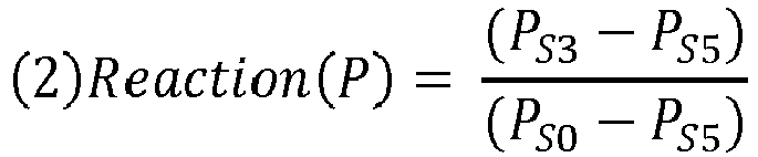
- Reaction P P S 3 ⁇ P S 5 P S 0 ⁇ P S 5
- T temperature and P is pressure
- s refers to a static port
- the numbers refers to the location the temperature or pressure is measured: 0 for the inlet of the turbine vane (stator), 3 for the inlet of the turbine blade (rotor) and 5 for the exit of the turbine blade (rotor); and where a pure impulse turbine would have a ratio of 0 (0%) and a pure reaction turbine would have a ratio of 1 (100%).
- Aeronautical turbines referred to as impulse turbines typically have a reaction ration of 0.25 (25% reaction) or lower, although other values are also possible.
- the first stage turbine 26 is configured to take benefit of the kinetic energy of the pulsating flow exiting the core engine(s) 12 while stabilizing the flow, and the second stage turbine 22 is configured to extract energy from the remaining pressure in the flow. Accordingly, the first stage turbine 26 has a lower (i.e. lower value) reaction ratio than that of the second stage turbine 22.
- the second stage turbine 22 has a reaction ratio higher than 0.25; in another particular embodiment, the second stage turbine 22 has a reaction ratio higher than 0.3; in another particular embodiment, the second stage turbine 22 has a reaction ratio of about 0.5; in another particular embodiment, the second stage turbine 22 has a reaction ratio higher than 0.5.
- the first stage turbine 26 has a reaction ratio of at most 0.2; in another particular embodiment, the first stage turbine 26 has a reaction ratio of at most 0.15; in another particular embodiment, the first stage turbine 26 has a reaction ratio of at most 0.1; in another particular embodiment, the first stage turbine 26 has a reaction ratio of at most 0.05.
- reaction ratios for the second stage turbine 22 can be combined with any of the above-mentioned reaction ratios for the first stage turbine 26 and that these ratios can be pressure-based or temperature-based. Other values are also possible.
- the first stage turbine 26 is connected to the output shaft 16 through an appropriate type of transmission 28, for example a planetary, star, offset or angular gear system.
- the outlet of the first stage turbine 26 is in fluid communication with an inlet of the second stage turbine 22. Energy is extracted from the exhaust gas exiting the first stage turbine 26 by the second stage turbine 22 to drive the compressor 20 via the connecting shaft 24.
- the air may optionally circulate through an intercooler between the compressor 20 and the core engine(s) 12, and the first stage engine assembly 10 also includes a cooling system, including for example a circulation system for a coolant (e.g. water-ethylene, oil, air) to cool the housing of each core engine 12, an oil coolant for the internal mechanical parts of the core engine(s) 12, one or more coolant heat exchangers, etc.
- a coolant e.g. water-ethylene, oil, air
- each core engine 12 which in a particular embodiment are common rail fuel injectors, communicate with a source 30 of Heavy fuel (e.g. diesel, kerosene (jet fuel), equivalent biofuel), and deliver the heavy fuel into the core engine(s) 12 such that the combustion chamber is stratified with a rich fuel-air mixture near the ignition source and a leaner mixture elsewhere.
- Heavy fuel e.g. diesel, kerosene (jet fuel), equivalent biofuel
- each core engine 12 is a rotary internal combustion engine having a rotor sealingly engaged in a respective housing.
- the rotary engine(s) is/are Wankel engine(s). Referring to Fig. 2 , an exemplary embodiment of a Wankel engine is shown; it is understood that the configuration of the core engine(s) 12 used in the compound engine assembly 10, e.g. placement of ports, number and placement of seals, etc., may vary from that of the embodiment shown.
- each core engine 12 may be any other type of internal combustion engine including, but not limited to, any other type of rotary engine.
- each Wankel engine comprises a housing 32 defining an internal cavity with a profile defining two lobes, which is preferably an epitrochoid.
- a rotor 34 is received within the internal cavity.
- the rotor defines three circumferentially-spaced apex portions 36, and a generally triangular profile with outwardly arched sides.
- the apex portions 36 are in sealing engagement with the inner surface of a peripheral wall 38 of the housing 32 to form three working chambers 40 between the rotor 34 and the housing 32.
- the rotor 34 is engaged to an eccentric portion 42 of the output shaft 16 to perform orbital revolutions within the internal cavity.
- the output shaft 16 performs three rotations for each orbital revolution of the rotor 34.
- the geometrical axis 44 of the rotor 34 is offset from and parallel to the axis 46 of the housing 32.
- each chamber 40 varies in volume and moves around the internal cavity to undergo the four phases of intake, compression, expansion and exhaust.
- the difference between the maximum and minimum volumes of each chamber 40 during the revolutions of the rotor 34 defines a displacement volume Vd of the engine.
- An intake port 48 is provided through the peripheral wall 38 for successively admitting compressed air into each working chamber 40.
- An exhaust port 50 is also provided through the peripheral wall 38 for successively discharging the exhaust gases from each working chamber 40.
- Passages 52 for a glow plug, spark plug or other ignition element, as well as for one or more fuel injectors (not shown) are also provided through the peripheral wall 38.
- the intake port 48, the exhaust port 50 and/or the passages 52 may be provided through an end or side wall 54 of the housing; and/or, the ignition element and a pilot fuel injector may communicate with a pilot subchamber (not shown) defined in the housing 32 and communicating with the internal cavity for providing a pilot injection.
- the pilot subchamber may be for example defined in an insert (not shown) received in the peripheral wall 38.
- the working chambers 40 are sealed, for example by spring-loaded apex seals 56 extending from the rotor 34 to engage the peripheral wall 38, and spring-loaded face or gas seals 58 and end or corner seals 60 extending from the rotor 34 to engage the end walls 54.
- the rotor 34 also includes at least one spring-loaded oil seal ring 62 biased against the end wall 54 around the bearing for the rotor 34 on the shaft eccentric portion 42.
- Each Wankel engine provides an exhaust flow in the form of a relatively long exhaust pulse; for example, in a particular embodiment, each Wankel engine has one explosion per 360° of rotation of the output shaft, with the exhaust port remaining open for about 270° of that rotation, thus providing for a pulse duty cycle of about 75%.
- a piston of a reciprocating 4-stroke piston engine typically has one explosion per 720° of rotation of the output shaft with the exhaust port remaining open for about 180° of that rotation, thus providing a pulse duty cycle of 25%.
- each Wankel engine has a volumetric expansion ratio of from 5 to 9, and a volumetric compression ratio lower than the volumetric expansion ratio.
- the power recovery of the first stage turbine 26 may be maximized by having the exhaust gas temperatures at the material limit, and as such is suitable for such relatively low volumetric compression ratios, which may help increase the power density of the Wankel engine and may also improve combustion at high speed and of heavy fuel.
- the compound engine assembly 10 includes two (2) core engines 12 in the form of Wankel engines, for example such as shown in Fig. 2 , with the two eccentric portions 42 of the output shaft 16 being angularly offset at 180° from one another for balancing of the compound engine assembly 10.
- more or less core engines 12 may be provided; for example, in another particular embodiment, the core includes four (4) Wankel engines.
- the transmission 28 of the first stage turbine 26 includes a sun gear 76 attached on the shaft of the rotor of the first stage turbine 26, and an array of planet gears 78 meshed with the sun gear 76.
- the planet gears 78 are mounted on a rotating carrier which is drivingly engaged to the output shaft 16.
- the planet gears 78 are meshed with a stationary ring gear 79.
- the planet gears 78 are mounted on a stationary carrier, and are meshed with a ring gear drivingly engaged to the output shaft 16.
- the speed reduction ratio of the transmission 28 may be selected to optimize operation of the first stage turbine 26 and of the core engines 12.
- the first stage turbine 26 may be mounted in an offset manner rather than co-axially with the core engines 12.
- the first stage turbine 26 may be drivingly engaged to the output shaft 16 through an angular, for example perpendicular, transmission system, for example including a gearbox and a tower shaft.
- the rotor blades 64 of the first stage turbine 26 extend across an annular flow path 66.
- the rotor of the first stage turbine 26 is an axial rotor and the flow path 66 extends axially.
- variable geometry elements such as inlet guide vanes, blow-off valves, waste gates, etc. may be used to obtain desired system operability.
- the assembly 10 includes an exhaust pipe 68 for each core engine 12.
- Each exhaust pipe 68 extends from the respective exhaust port 50 (see also Fig. 2 ) of the respective core engine 12 to a portion of the first stage turbine flow path 66 located upstream of the rotor blades 64, to provide the fluid communication therebetween.
- each exhaust pipe 68 is shaped to direct the exhaust pulses onto the blades 64 to allow the exhaust pulses to drive rotation of the rotor of the first stage turbine 26.
- the exhaust pipes 68 extend independently from one another, and have a relatively small length, which in a particular embodiment allows for increased use of the exhaust pulse kinetic energy to drive the first stage turbine 26.
- the length of the exhaust pipes 68 is small enough such that the ratio Vp/Vd between the internal volume Vp of each exhaust pipe 68 and the displacement volume Vd of the corresponding core engine 12 is at most 1.5; in another particular embodiment, the ratio Vp/Vd is at most 1.2; in another particular embodiment, the ratio Vp/Vd is at most 1.0.
- Shorter exhaust pipes 68 can lead to high pressures at the exhaust pipe outlet; a higher flow pressure cause a higher density of the flow, which leads to a lower flow speed; lower flow speed may in turn lead to lower energy recovery in the first stage turbine 26.
- this effect is compensated by including a nozzle 70 in the portion of each exhaust pipe 68 defining the communication with the first stage turbine flow path 66.
- the nozzle 70 is located at the outlet end of the exhaust pipe 68, immediately upstream of the flow path 66.
- the nozzle 70 defines the minimal cross-sectional area of each exhaust pipe 68.
- the reduced cross-section of the exhaust pipe 68 defined by the nozzle 70 allows for the flow speed through the nozzle 70 to be increased, which in a particular embodiment allows to obtain improved energy recovery in the first stage turbine 26 with respect to an exhaust pipe 68 of similar length and volume but with a constant cross-section throughout its entire length.
- the nozzles 70 and accordingly the communications between the exhaust pipes 68 and the first stage turbine flow path 66 are spaced apart around the circumferential direction of the first stage turbine 26.
- each exhaust pipe 68 is constant upstream of the nozzle 70, for example in the portion 69 of the exhaust pipe 68 extending from its communication with the exhaust port 50 to the nozzle 70, and this constant cross-sectional area corresponds to that of the engine exhaust port 50 connected to the exhaust pipe 68.
- the exhaust pipe 68 may have a different cross-sectional area than that of the exhaust port 50, and may be for example smaller than that of the corresponding exhaust port 50.
- the ratio An/Ae between the minimum value An of the cross-sectional area of each exhaust pipe 68 at the nozzle 70 and the cross-sectional area Ae of the corresponding exhaust port 50 is at least 0.2. In other embodiments, the ratio An/Ae may be at least 0.4, at most 0.6, from 0.2 to 0.6, or from 0.4 to 0.6. In a particular embodiment, the ratio An/Ae is about 0.5. Other values are also possible.
- an inlet pipe 72 is connected to each intake port 48 (see also Fig. 2 ), and if a turbocharger is provided, provides fluid communication between the intake port 48 and the outlet of the compressor 20 ( Fig. 1 ).
- a turbine pipe 80 extends from the flow path 66 of the first stage turbine 26 downstream of the rotor blades 64, and if a turbocharger is provided, provides fluid communication between the first stage turbine 26 exhaust and the inlet of the second stage turbine 22 ( Fig. 1 ).
- the internal combustion engine(s) 12 of the engine core are compounded by providing the first stage turbine 26, drivingly engaging each engine 12 and the first stage turbine 26 to a common load, circulating the exhaust gas from each exhaust port 50 through a first portion 69 of the respective exhaust pipe 68, for example having the same cross-sectional area Ae as that of the exhaust port 50, and then through the nozzle 70 having a cross-sectional area An smaller than that of the first portion 69.
- the exhaust gas is then circulated from the nozzle to the inlet of the first stage turbine 26, and directed onto the blades 64 of its rotor.
- Figs. 4-5 show examples of the effect of the presence of the nozzle 70 (reduced cross-sectional area) at the outlet of the exhaust pipe 68.
- the two graphs show the comparison between two assemblies similar to the assembly 10 described above, the assemblies being identical aside from the configuration of their exhaust pipes 68.
- Both assemblies include exhaust pipes defining a ratio Vp/Vd of 0.8.
- the exhaust pipes include a nozzle at their outlet end defining a ratio An/Ae of 0.95, i.e. the cross-sectional area of the exhaust pipes is not substantially reduced at the connection with the first stage turbine flow path 66.
- the exhaust pipes include a nozzle at their outlet end defining a ratio An/Ae of 0.48.
- Fig. 4 the pressure variation with respect to the crank angle of the output shaft 16 is shown. It can be seen that the static pressure pulse P 1 of the assembly with the larger exit nozzles (An/Ae of 0.95) is lower than the static pressure pulse P 2 of the assembly with the smaller exit nozzles (An/Ae of 0.48); with the larger nozzles, more flow exits the pipe at the beginning of the pulse because of the larger cross-sectional area, and accordingly the pressure build up is less steep.
- Fig. 5 the variation in flow speed (Mach number - MN) at the outlet of the exhaust pipe adjacent the turbine inlet or communication with the first stage turbine flow path 66 with respect to the crank angle of the output shaft 16 is shown.
- M MAX which in a particular embodiment corresponds to Mach 1
- M 2 the assembly with the smaller exit nozzles
- An/Ae of 0.95 the assembly with the larger exit nozzles
- the flow speed at the turbine inlet M 2 of the assembly including the smaller exit nozzles reaches a maximal value M MAX of about Mach 1, and a mean value of about Mach 0.8.
- M MAX maximal value
- M mean value mean value of Mach 0.8.
- the nozzles 70 create equivalent or higher flow speeds at the outlet ends of short exhaust pipes than that obtained at the outlet ends of long exhaust pipes which are sufficiently long to avoid pressure increases leading to flow speed reductions, while avoiding the energy losses associated with the dampening of the exhaust pulses occurring across the length of such long exhaust pipes.
Landscapes
- Engineering & Computer Science (AREA)
- Mechanical Engineering (AREA)
- General Engineering & Computer Science (AREA)
- Chemical & Material Sciences (AREA)
- Combustion & Propulsion (AREA)
- Chemical Kinetics & Catalysis (AREA)
- General Chemical & Material Sciences (AREA)
- Supercharger (AREA)
Abstract
Description
- The application relates generally to compound engine assemblies and, more particularly, to such compound engine assemblies including one or more rotary internal combustion engine(s).
- Compound engine assemblies including an impulse turbine with a reciprocating engine core are known and typically include long exhaust pipes with a relatively high pipe volume which is sufficient to maintain the pressure of the exhaust pulses at an acceptable level corresponding to an acceptable flow speed at the connection with the impulse turbine. However, longer exhaust pipes typically lead to greater power losses from the exhaust pulse and accordingly, less recovery in the compound turbine.
- In one aspect, there is provided a compound engine assembly comprising: an engine core including at least one internal combustion engine, each internal combustion engine defining an internal cavity and including a rotor sealingly and rotationally received within the internal cavity to provide rotating chambers of variable volume in the internal cavity, the volume of each of the rotating chambers varying between a minimum volume and a maximum volume with a difference between the maximum and minimum volumes defining a displacement volume Vd, each internal combustion engine having an inlet port and an exhaust port in communication with the internal cavity; a turbine configured as an impulse turbine having a pressure based reaction ratio of at most 0.25, the turbine including a rotor including a circumferential array of rotor blades extending across a flow path; and an exhaust pipe for each internal combustion engine, each exhaust pipe having a pipe volume Vp, each exhaust pipe providing fluid communication between the exhaust port of a respective one of the at least one internal combustion engine and the flow path of the turbine, each exhaust pipe terminating in a nozzle communicating with a portion of the flow path located upstream of the rotor blades; wherein for each exhaust pipe, a ratio Vp/Vd between the pipe volume Vp and the displacement volume Vd of the respective one of the at least one internal combustion engine is at most 1.5; and wherein a minimum value of a cross-sectional area of each exhaust pipe is defined at the nozzle.
- In another aspect, there is provided a compound engine assembly comprising: an engine core including at least one internal combustion engine, each internal combustion engine defining an internal cavity and including a rotor sealingly and rotationally received within the internal cavity to provide rotating chambers of variable volume in the internal cavity, each internal combustion engine having an inlet port and an exhaust port in communication with the internal cavity, each exhaust port having a cross-sectional area Ae; a turbine configured as an impulse turbine having a pressure based reaction ratio of at most 0.25, the turbine including a rotor having a circumferential array of rotor blades extending across a flow path; and an exhaust pipe for each internal combustion engine, each exhaust pipe providing fluid communication between the exhaust port of a respective one of the at least one internal combustion engine and the flow path of the turbine, each exhaust pipe terminating in a nozzle communicating with a portion of the flow path located upstream of the rotor blades; wherein for each exhaust pipe, the nozzle includes a portion of reduced cross-sectional area with respect to a remainder of the exhaust pipe, the nozzle defining a minimum cross-sectional area An of the exhaust pipe; and wherein for each exhaust pipe, a ratio An/Ae between the minimum cross-sectional area An and the cross-sectional area Ae of the exhaust port of the respective one of the at least one internal combustion engine is at least 0.2.
- In a further aspect, there is provided a method of compounding at least one rotary engine, the method comprising: providing a turbine configured as an impulse turbine having a pressure based reaction ratio of at most 0.25; drivingly engaging each rotary engine and the turbine to a common load; circulating exhaust gas from an exhaust port of each rotary engine through a first portion of a respective exhaust pipe having a first cross-sectional area and then through a nozzle of the respective exhaust pipe having a second cross-sectional area smaller than the first cross-sectional area; and circulating the exhaust gas from the nozzle to an inlet of the turbine, including directing the exhaust gas onto blades of a rotor of the turbine.
- Reference is now made to the accompanying figures in which:
-
Fig. 1 is a block diagram of a compound engine assembly according to a particular embodiment; -
Fig. 2 is a cross-sectional view of a Wankel engine which can be used in a compound engine assembly such as shown inFig. 1 , according to a particular embodiment; -
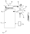
Fig. 3 is a schematic representation of part of the compound engine assembly ofFig. 1 according to a particular embodiment; -
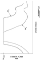
Fig. 4 is a schematic graph of pressure variation with respect to crank angle, for a compound engine including exhaust pipes with a constant cross-sectional area and for a compound engine including exhaust pipes with nozzles as per a particular embodiment; and -
Fig. 5 is a schematic graph of flow speed variation with respect to crank angle, for the compound engine including exhaust pipes with a constant cross-sectional area and for the compound engine including exhaust pipes with nozzles. - Referring to
Fig. 1 , acompound engine assembly 10 is schematically shown. Thecompound engine assembly 10 includes an engine core with one or more internal combustion engine(s) 12. The core engine(s) 12 drive a common load. In the embodiment shown, the common load includes anoutput shaft 16 which may be for example connected to a propeller through a reduction gearbox (not shown) and to which eachcore engine 12 is engaged. Other possible common loads may include, but are not limited to, one or more compressor and/or fan rotor(s), electrical generator(s), accessories, rotor mast(s), or any other type of load or combination thereof. - In a particular embodiment, the
compound engine assembly 10 also includes aturbocharger 18, including acompressor 20 and asecond stage turbine 22 which are drivingly interconnected by ashaft 24. In a particular embodiment, thesecond stage turbine 22 is a pressure turbine, also known as a reaction turbine. Thecompressor 20 and thesecond stage turbine 22 may each be a single-stage device or a multiple-stage device with a single shaft or split on multiple independent shafts in parallel or in series, and may each be a centrifugal or axial device. Thecompressor 20 of theturbocharger 18 compresses the air before it enters the core engine(s) 12. Thecompressor 20 and thesecond stage turbine 22 may each include one or more rotors, with radial, axial or mixed flow blades. - In the embodiment shown, the
shaft 24 of theturbocharger 18 rotates independently of the common load. Theturbocharger shaft 24 may extends along a different axis than that of theoutput shaft 16, for example transverse to theoutput shaft 16, or may be defined coaxially with theoutput shaft 16; the turbocharger shaft andoutput shaft 16 may be linked to rotate together, for example through a transmission, or may rotate independently from one another. - Alternately, the
turbocharger 18 may be omitted. - Each
core engine 12 provides an exhaust flow in the form of exhaust pulses. The exhaust flow from thecore engines 12 is supplied to a compound orfirst stage turbine 26 in fluid communication therewith, also driving the common load. Thefirst stage turbine 26 is configured as a velocity type turbine, also known as an impulse turbine, and could be an axial, radial or mixed flow turbine. - A pure impulse turbine works by changing the direction of the flow without accelerating the flow inside the rotor; the fluid is deflected without a significant pressure drop across the rotor blades. The blades of the pure impulse turbine are designed such that in a transverse plane perpendicular to the direction of flow, the area defined between the blades is the same at the leading edges of the blades and at the trailing edges of the blade: the flow area of the turbine is constant, and the blades are usually symmetrical about the plane of the rotating disc. The work of the pure impulse turbine is due only to the change of direction in the flow through the turbine blades. Typical pure impulse turbines include steam and hydraulic turbines.
- In contrast, a reaction turbine accelerates the flow inside the rotor but needs a static pressure drop across the rotor to enable this flow acceleration. The blades of the reaction turbine are designed such that in a transverse plane perpendicular to the direction of flow, the area defined between the blades is larger at the leading edges of the blades than at the trailing edges of the blade: the flow area of the turbine reduces along the direction of flow, and the blades are usually not symmetrical about the plane of the rotating disc. The work of the pure reaction turbine is due mostly to the acceleration of the flow through the turbine blades.
- Most aeronautical turbines are not "pure impulse" or "pure reaction", but rather operate following a mix of these two opposite but complementary principles - i.e. there is a pressure drop across the blades, there is some reduction of flow area of the turbine blades along the direction of flow, and the speed of rotation of the turbine is due to both the acceleration and the change of direction of the flow. The degree of reaction of a turbine can be determined using the temperature-based reaction ratio (equation 1) or the pressure-based reaction ratio (equation 2), which are typically close to one another in value for a same turbine:

- Aeronautical turbines referred to as impulse turbines typically have a reaction ration of 0.25 (25% reaction) or lower, although other values are also possible.
- In a particular embodiment, the
first stage turbine 26 is configured to take benefit of the kinetic energy of the pulsating flow exiting the core engine(s) 12 while stabilizing the flow, and thesecond stage turbine 22 is configured to extract energy from the remaining pressure in the flow. Accordingly, thefirst stage turbine 26 has a lower (i.e. lower value) reaction ratio than that of thesecond stage turbine 22. - In a particular embodiment, the
second stage turbine 22 has a reaction ratio higher than 0.25; in another particular embodiment, thesecond stage turbine 22 has a reaction ratio higher than 0.3; in another particular embodiment, thesecond stage turbine 22 has a reaction ratio of about 0.5; in another particular embodiment, thesecond stage turbine 22 has a reaction ratio higher than 0.5. - In a particular embodiment, the
first stage turbine 26 has a reaction ratio of at most 0.2; in another particular embodiment, thefirst stage turbine 26 has a reaction ratio of at most 0.15; in another particular embodiment, thefirst stage turbine 26 has a reaction ratio of at most 0.1; in another particular embodiment, thefirst stage turbine 26 has a reaction ratio of at most 0.05. - It is understood that any of the above-mentioned reaction ratios for the
second stage turbine 22 can be combined with any of the above-mentioned reaction ratios for thefirst stage turbine 26 and that these ratios can be pressure-based or temperature-based. Other values are also possible. - In the embodiment shown, the
first stage turbine 26 is connected to theoutput shaft 16 through an appropriate type oftransmission 28, for example a planetary, star, offset or angular gear system. The outlet of thefirst stage turbine 26 is in fluid communication with an inlet of thesecond stage turbine 22. Energy is extracted from the exhaust gas exiting thefirst stage turbine 26 by thesecond stage turbine 22 to drive thecompressor 20 via theconnecting shaft 24. - Although not shown, the air may optionally circulate through an intercooler between the
compressor 20 and the core engine(s) 12, and the firststage engine assembly 10 also includes a cooling system, including for example a circulation system for a coolant (e.g. water-ethylene, oil, air) to cool the housing of eachcore engine 12, an oil coolant for the internal mechanical parts of the core engine(s) 12, one or more coolant heat exchangers, etc. - The fuel injector(s) of each
core engine 12, which in a particular embodiment are common rail fuel injectors, communicate with asource 30 of Heavy fuel (e.g. diesel, kerosene (jet fuel), equivalent biofuel), and deliver the heavy fuel into the core engine(s) 12 such that the combustion chamber is stratified with a rich fuel-air mixture near the ignition source and a leaner mixture elsewhere. - In a particular embodiment, each
core engine 12 is a rotary internal combustion engine having a rotor sealingly engaged in a respective housing. In a particular embodiment, the rotary engine(s) is/are Wankel engine(s). Referring toFig. 2 , an exemplary embodiment of a Wankel engine is shown; it is understood that the configuration of the core engine(s) 12 used in thecompound engine assembly 10, e.g. placement of ports, number and placement of seals, etc., may vary from that of the embodiment shown. In addition, it is understood that eachcore engine 12 may be any other type of internal combustion engine including, but not limited to, any other type of rotary engine. - As shown in
Fig. 2 , each Wankel engine comprises ahousing 32 defining an internal cavity with a profile defining two lobes, which is preferably an epitrochoid. Arotor 34 is received within the internal cavity. The rotor defines three circumferentially-spacedapex portions 36, and a generally triangular profile with outwardly arched sides. Theapex portions 36 are in sealing engagement with the inner surface of aperipheral wall 38 of thehousing 32 to form threeworking chambers 40 between therotor 34 and thehousing 32. - The
rotor 34 is engaged to aneccentric portion 42 of theoutput shaft 16 to perform orbital revolutions within the internal cavity. Theoutput shaft 16 performs three rotations for each orbital revolution of therotor 34. Thegeometrical axis 44 of therotor 34 is offset from and parallel to theaxis 46 of thehousing 32. During each orbital revolution, eachchamber 40 varies in volume and moves around the internal cavity to undergo the four phases of intake, compression, expansion and exhaust. The difference between the maximum and minimum volumes of eachchamber 40 during the revolutions of therotor 34 defines a displacement volume Vd of the engine. - An
intake port 48 is provided through theperipheral wall 38 for successively admitting compressed air into each workingchamber 40. Anexhaust port 50 is also provided through theperipheral wall 38 for successively discharging the exhaust gases from each workingchamber 40.Passages 52 for a glow plug, spark plug or other ignition element, as well as for one or more fuel injectors (not shown) are also provided through theperipheral wall 38. Alternately, theintake port 48, theexhaust port 50 and/or thepassages 52 may be provided through an end orside wall 54 of the housing; and/or, the ignition element and a pilot fuel injector may communicate with a pilot subchamber (not shown) defined in thehousing 32 and communicating with the internal cavity for providing a pilot injection. The pilot subchamber may be for example defined in an insert (not shown) received in theperipheral wall 38. - For efficient operation the working
chambers 40 are sealed, for example by spring-loaded apex seals 56 extending from therotor 34 to engage theperipheral wall 38, and spring-loaded face orgas seals 58 and end or corner seals 60 extending from therotor 34 to engage theend walls 54. Therotor 34 also includes at least one spring-loadedoil seal ring 62 biased against theend wall 54 around the bearing for therotor 34 on the shafteccentric portion 42. - Each Wankel engine provides an exhaust flow in the form of a relatively long exhaust pulse; for example, in a particular embodiment, each Wankel engine has one explosion per 360° of rotation of the output shaft, with the exhaust port remaining open for about 270° of that rotation, thus providing for a pulse duty cycle of about 75%. By contrast, a piston of a reciprocating 4-stroke piston engine typically has one explosion per 720° of rotation of the output shaft with the exhaust port remaining open for about 180° of that rotation, thus providing a pulse duty cycle of 25%.
- In a particular embodiment which may be particularly but not exclusively suitable for low altitude, each Wankel engine has a volumetric expansion ratio of from 5 to 9, and a volumetric compression ratio lower than the volumetric expansion ratio. The power recovery of the
first stage turbine 26 may be maximized by having the exhaust gas temperatures at the material limit, and as such is suitable for such relatively low volumetric compression ratios, which may help increase the power density of the Wankel engine and may also improve combustion at high speed and of heavy fuel. - Referring to
Fig. 3 , in a particular embodiment, thecompound engine assembly 10 includes two (2)core engines 12 in the form of Wankel engines, for example such as shown inFig. 2 , with the twoeccentric portions 42 of theoutput shaft 16 being angularly offset at 180° from one another for balancing of thecompound engine assembly 10. In other embodiments, more or lesscore engines 12 may be provided; for example, in another particular embodiment, the core includes four (4) Wankel engines. - In the embodiment shown, the
transmission 28 of thefirst stage turbine 26 includes asun gear 76 attached on the shaft of the rotor of thefirst stage turbine 26, and an array of planet gears 78 meshed with thesun gear 76. The planet gears 78 are mounted on a rotating carrier which is drivingly engaged to theoutput shaft 16. The planet gears 78 are meshed with astationary ring gear 79. In another embodiment, the planet gears 78 are mounted on a stationary carrier, and are meshed with a ring gear drivingly engaged to theoutput shaft 16. The speed reduction ratio of thetransmission 28 may be selected to optimize operation of thefirst stage turbine 26 and of thecore engines 12. Other configurations are also possible. For example, thefirst stage turbine 26 may be mounted in an offset manner rather than co-axially with thecore engines 12. Thefirst stage turbine 26 may be drivingly engaged to theoutput shaft 16 through an angular, for example perpendicular, transmission system, for example including a gearbox and a tower shaft. - The
rotor blades 64 of thefirst stage turbine 26 extend across anannular flow path 66. In the embodiment shown, the rotor of thefirst stage turbine 26 is an axial rotor and theflow path 66 extends axially. Although not shown, in all embodiments, variable geometry elements such as inlet guide vanes, blow-off valves, waste gates, etc. may be used to obtain desired system operability. - The
assembly 10 includes anexhaust pipe 68 for eachcore engine 12. Eachexhaust pipe 68 extends from the respective exhaust port 50 (see alsoFig. 2 ) of therespective core engine 12 to a portion of the first stageturbine flow path 66 located upstream of therotor blades 64, to provide the fluid communication therebetween. - The
flow path 66 and/or the outlet of eachexhaust pipe 68 are shaped to direct the exhaust pulses onto theblades 64 to allow the exhaust pulses to drive rotation of the rotor of thefirst stage turbine 26. Theexhaust pipes 68 extend independently from one another, and have a relatively small length, which in a particular embodiment allows for increased use of the exhaust pulse kinetic energy to drive thefirst stage turbine 26. In a particular embodiment, the length of theexhaust pipes 68 is small enough such that the ratio Vp/Vd between the internal volume Vp of eachexhaust pipe 68 and the displacement volume Vd of the correspondingcore engine 12 is at most 1.5; in another particular embodiment, the ratio Vp/Vd is at most 1.2; in another particular embodiment, the ratio Vp/Vd is at most 1.0. -
Shorter exhaust pipes 68 can lead to high pressures at the exhaust pipe outlet; a higher flow pressure cause a higher density of the flow, which leads to a lower flow speed; lower flow speed may in turn lead to lower energy recovery in thefirst stage turbine 26. In a particular embodiment, this effect is compensated by including anozzle 70 in the portion of eachexhaust pipe 68 defining the communication with the first stageturbine flow path 66. In the embodiment shown, thenozzle 70 is located at the outlet end of theexhaust pipe 68, immediately upstream of theflow path 66. Thenozzle 70 defines the minimal cross-sectional area of eachexhaust pipe 68. The reduced cross-section of theexhaust pipe 68 defined by thenozzle 70 allows for the flow speed through thenozzle 70 to be increased, which in a particular embodiment allows to obtain improved energy recovery in thefirst stage turbine 26 with respect to anexhaust pipe 68 of similar length and volume but with a constant cross-section throughout its entire length. - In the embodiment shown, the
nozzles 70 and accordingly the communications between theexhaust pipes 68 and the first stageturbine flow path 66 are spaced apart around the circumferential direction of thefirst stage turbine 26. - In the embodiment shown, the cross-sectional area of each
exhaust pipe 68 is constant upstream of thenozzle 70, for example in theportion 69 of theexhaust pipe 68 extending from its communication with theexhaust port 50 to thenozzle 70, and this constant cross-sectional area corresponds to that of theengine exhaust port 50 connected to theexhaust pipe 68. Alternately, theexhaust pipe 68 may have a different cross-sectional area than that of theexhaust port 50, and may be for example smaller than that of thecorresponding exhaust port 50. - In a particular embodiment, the ratio An/Ae between the minimum value An of the cross-sectional area of each
exhaust pipe 68 at thenozzle 70 and the cross-sectional area Ae of thecorresponding exhaust port 50 is at least 0.2. In other embodiments, the ratio An/Ae may be at least 0.4, at most 0.6, from 0.2 to 0.6, or from 0.4 to 0.6. In a particular embodiment, the ratio An/Ae is about 0.5. Other values are also possible. - In addition, an
inlet pipe 72 is connected to each intake port 48 (see alsoFig. 2 ), and if a turbocharger is provided, provides fluid communication between theintake port 48 and the outlet of the compressor 20 (Fig. 1 ). Aturbine pipe 80 extends from theflow path 66 of thefirst stage turbine 26 downstream of therotor blades 64, and if a turbocharger is provided, provides fluid communication between thefirst stage turbine 26 exhaust and the inlet of the second stage turbine 22 (Fig. 1 ). - Accordingly, in a particular embodiment, the internal combustion engine(s) 12 of the engine core are compounded by providing the
first stage turbine 26, drivingly engaging eachengine 12 and thefirst stage turbine 26 to a common load, circulating the exhaust gas from eachexhaust port 50 through afirst portion 69 of therespective exhaust pipe 68, for example having the same cross-sectional area Ae as that of theexhaust port 50, and then through thenozzle 70 having a cross-sectional area An smaller than that of thefirst portion 69. The exhaust gas is then circulated from the nozzle to the inlet of thefirst stage turbine 26, and directed onto theblades 64 of its rotor. -
Figs. 4-5 show examples of the effect of the presence of the nozzle 70 (reduced cross-sectional area) at the outlet of theexhaust pipe 68. The two graphs show the comparison between two assemblies similar to theassembly 10 described above, the assemblies being identical aside from the configuration of theirexhaust pipes 68. Both assemblies include exhaust pipes defining a ratio Vp/Vd of 0.8. In the first assembly, the exhaust pipes include a nozzle at their outlet end defining a ratio An/Ae of 0.95, i.e. the cross-sectional area of the exhaust pipes is not substantially reduced at the connection with the first stageturbine flow path 66. In the second assembly, the exhaust pipes include a nozzle at their outlet end defining a ratio An/Ae of 0.48. - In
Fig. 4 , the pressure variation with respect to the crank angle of theoutput shaft 16 is shown. It can be seen that the static pressure pulse P1 of the assembly with the larger exit nozzles (An/Ae of 0.95) is lower than the static pressure pulse P2 of the assembly with the smaller exit nozzles (An/Ae of 0.48); with the larger nozzles, more flow exits the pipe at the beginning of the pulse because of the larger cross-sectional area, and accordingly the pressure build up is less steep. - In
Fig. 5 , the variation in flow speed (Mach number - MN) at the outlet of the exhaust pipe adjacent the turbine inlet or communication with the first stageturbine flow path 66 with respect to the crank angle of theoutput shaft 16 is shown. It can be seen that the time during which the speed of the flow is at the maximum value MMAX (which in a particular embodiment corresponds to Mach 1) is longer for the assembly with the smaller exit nozzles (An/Ae of 0.48), as shown by M2, than for the assembly with the larger exit nozzles (An/Ae of 0.95), as shown by M1. Thus, the presence of the reduced cross-sectional area as defined by thesmaller nozzles 70 allows for an increase in mean flow speed at the first stage turbine inlet. In a particular embodiment, the flow speed at the turbine inlet M2 of the assembly including the smaller exit nozzles (An/Ae of 0.48) reaches a maximal value MMAX of aboutMach 1, and a mean value of about Mach 0.8. Other values are also possible. In a particular embodiment, the larger mean value of flow speed provides for a better performance of thefirst stage turbine 26, and the larger portion of the full 360 degrees crank angle cycle at the maximal value Mn=1 allows for the transient effects of the pulsating flow in the turbine to be less disturbing and closer to a constant flow turbine, which may yield better efficiency. - In a particular embodiment, the
nozzles 70 create equivalent or higher flow speeds at the outlet ends of short exhaust pipes than that obtained at the outlet ends of long exhaust pipes which are sufficiently long to avoid pressure increases leading to flow speed reductions, while avoiding the energy losses associated with the dampening of the exhaust pulses occurring across the length of such long exhaust pipes. - The above description is meant to be exemplary only, and one skilled in the art will recognize that changes may be made to the embodiments described without departing from the scope of the invention disclosed. Modifications which fall within the scope of the present invention will be apparent to those skilled in the art, in light of a review of this disclosure, and such modifications are intended to fall within the appended claims.
Claims (14)
- A compound engine assembly (10) comprising:an engine core including at least one internal combustion engine (12), each internal combustion engine (12) defining an internal cavity and including a rotor (34) sealingly and rotationally received within the internal cavity to provide rotating chambers (40) of variable volume in the internal cavity, the volume of each of the rotating chambers (40) varying between a minimum volume and a maximum volume with a difference between the maximum and minimum volumes defining a displacement volume Vd, each internal combustion engine (12) having an inlet port (48) and an exhaust port (50) in communication with the internal cavity;a turbine configured as an impulse turbine having a pressure based reaction ratio of at most 0.25, the turbine including a rotor (34) including a circumferential array of rotor blades (64) extending across a flow path (60); andan exhaust pipe (68) for each internal combustion engine (12), each exhaust pipe (68) having a pipe volume Vp, each exhaust pipe (68) providing fluid communication between the exhaust port (50) of a respective one of the at least one internal combustion engine (12) and the flow path (60) of the turbine, each exhaust pipe (68) terminating in a nozzle (70) communicating with a portion of the flow path (60) located upstream of the rotor blades (64);wherein for each exhaust pipe (68), a ratio Vp/Vd between the pipe volume Vp and the displacement volume Vd of the respective one of the at least one internal combustion engine (12) is at most 1.5; and
wherein a minimum value of a cross-sectional area of each exhaust pipe (68) is defined at the nozzle (70). - The compound engine assembly (10) as defined in claim 1, wherein for each exhaust pipe (68), a ratio An/Ae between the minimum value An of the cross-sectional area at the nozzle (68) and a cross-sectional area Ae of the exhaust port (50) of the respective one of the at least one internal combustion engine (12) is at least 0.2.
- The compound engine assembly (10) as defined in claim 1 or 2, wherein the ratio Vp/Vd is at most 1.0.
- A compound engine assembly (10) comprising:an engine core including at least one internal combustion engine (12), each internal combustion engine (12) defining an internal cavity and including a rotor sealingly and rotationally received within the internal cavity to provide rotating chambers (40) of variable volume in the internal cavity, each internal combustion engine (12) having an inlet port (48) and an exhaust port (50) in communication with the internal cavity, each exhaust port (50) having a cross-sectional area Ae;a turbine configured as an impulse turbine having a pressure based reaction ratio of at most 0.25, the turbine including a rotor having a circumferential array of rotor blades (64) extending across a flow path (66); andan exhaust pipe (68) for each internal combustion engine (12), each exhaust pipe (68) providing fluid communication between the exhaust port (50) of a respective one of the at least one internal combustion engine (12) and the flow path of the turbine, each exhaust pipe (68) terminating in a nozzle (70) communicating with a portion of the flow path (60) located upstream of the rotor blades (64);wherein for each exhaust pipe (68), the nozzle (70) includes a portion of reduced cross-sectional area with respect to a remainder of the exhaust pipe (68), the nozzle (70) defining a minimum cross-sectional area An of the exhaust pipe (68); and
wherein for each exhaust pipe (68), a ratio An/Ae between the minimum cross-sectional area An and the cross-sectional area Ae of the exhaust port (50) of the respective one of the at least one internal combustion engine (12) is at least 0.2. - The compound engine assembly (10) as defined in any one of claims 2 to 4, wherein the ratio An/Ae is at most 0.6.
- The compound engine assembly (10) as defined in any one of claims 2 to 4, wherein the ratio An/Ae is at least 0.4.
- The compound engine assembly (10) as defined in any preceding claim, wherein the rotor (34) of the turbine and the rotor (34) of each internal combustion engine (12) are in driving engagement with a common load.
- The compound engine assembly (10) as defined in any preceding claim, wherein the cross-sectional area of each exhaust pipe (68) upstream of the nozzle (70) is constant.
- The compound engine assembly (10) as defined in claim 8, wherein the cross-sectional area of each exhaust pipe (68) upstream of the nozzle (70) corresponds to a cross-sectional area of the exhaust port (50) of the respective one of the at least one internal combustion engine (12).
- The compound engine assembly (10) as defined in any preceding claim, wherein each internal combustion engine (12) is a Wankel engine, the rotor (34) having three apex portions separating the rotating chambers (40) and mounted for eccentric revolutions within the internal cavity, the internal cavity having an epitrochoid shape with two lobes.
- The compound engine assembly (10) as defined in any preceding claim, wherein the turbine is a first stage turbine (26), the assembly (10) further comprising a turbocharger (18) including a compressor (20) and a second stage turbine (22) in driving engagement with one another, an outlet of the compressor being in fluid communication with the inlet port (48) of each internal combustion engine (12), and an inlet of the second stage turbine (22) being in fluid communication with a portion of the flow path (60) of the first stage turbine (26) located downstream of the rotor blades of the first stage turbine (26), the second stage turbine (22) having a pressure based reaction ratio higher than that of the first stage turbine (26).
- The compound engine assembly (10) as defined in any preceding claim, wherein the at least one internal combustion engine (12) includes first and second internal combustion engines (12), the nozzle (70) of the exhaust pipe (68) of the first internal combustion engine (12) being spaced apart from the nozzle (70) of the exhaust pipe (68) of the second internal combustion engine (12) along a circumferential direction of the turbine.
- The compound engine (10) assembly as defined in any preceding claim, further comprising a heavy fuel source in communication with each internal combustion engine (12).
- A method of compounding at least one rotary engine, the method comprising:providing a turbine configured as an impulse turbine having a pressure based reaction ratio of at most 0.25;drivingly engaging each rotary engine and the turbine to a common load;circulating exhaust gas from an exhaust port (50) of each rotary engine through a first portion of a respective exhaust pipe (68) having a first cross-sectional area and then through a nozzle (70) of the respective exhaust pipe (68) having a second cross-sectional area smaller than the first cross-sectional area; andcirculating the exhaust gas from the nozzle (70) to an inlet of the turbine, including directing the exhaust gas onto blades (64) of a rotor (34) of the turbine.
Priority Applications (1)
| Application Number | Priority Date | Filing Date | Title |
|---|---|---|---|
| PL16174872T PL3106609T3 (en) | 2015-06-16 | 2016-06-16 | Compound engine assembly with exhaust pipe nozzle |
Applications Claiming Priority (1)
| Application Number | Priority Date | Filing Date | Title |
|---|---|---|---|
| US14/740,889 US9759128B2 (en) | 2015-06-16 | 2015-06-16 | Compound engine assembly with exhaust pipe nozzle |
Publications (2)
| Publication Number | Publication Date |
|---|---|
| EP3106609A1 true EP3106609A1 (en) | 2016-12-21 |
| EP3106609B1 EP3106609B1 (en) | 2018-08-01 |
Family
ID=56321736
Family Applications (1)
| Application Number | Title | Priority Date | Filing Date |
|---|---|---|---|
| EP16174872.8A Active EP3106609B1 (en) | 2015-06-16 | 2016-06-16 | Compound engine assembly with exhaust pipe nozzle |
Country Status (7)
| Country | Link |
|---|---|
| US (2) | US9759128B2 (en) |
| EP (1) | EP3106609B1 (en) |
| CN (1) | CN107923308B (en) |
| CA (1) | CA2931575C (en) |
| ES (1) | ES2690156T3 (en) |
| PL (1) | PL3106609T3 (en) |
| WO (1) | WO2016201551A1 (en) |
Families Citing this family (3)
| Publication number | Priority date | Publication date | Assignee | Title |
|---|---|---|---|---|
| US9512721B2 (en) | 2012-07-20 | 2016-12-06 | Pratt & Whitney Canada Corp. | Compound cycle engine |
| JP2016061275A (en) * | 2014-09-22 | 2016-04-25 | マツダ株式会社 | On-vehicle rotary piston engine |
| US9771165B2 (en) * | 2015-06-25 | 2017-09-26 | Pratt & Whitney Canada Corp. | Compound engine assembly with direct drive of generator |
Citations (3)
| Publication number | Priority date | Publication date | Assignee | Title |
|---|---|---|---|---|
| EP2011962A2 (en) * | 2007-07-02 | 2009-01-07 | United Technologies Corporation | Compound cycle rotary engine |
| EP2687675A2 (en) * | 2012-07-20 | 2014-01-22 | Pratt & Whitney Canada Corp. | Compound cycle engine |
| EP2778342A2 (en) * | 2013-03-13 | 2014-09-17 | Pratt & Whitney Canada Corp. | Internal combustion engine with port communication |
Family Cites Families (44)
| Publication number | Priority date | Publication date | Assignee | Title |
|---|---|---|---|---|
| US1901873A (en) | 1926-08-17 | 1933-03-21 | Holzwarth Gas Turbine Co | Multistage constant volume explosion process and apparatus |
| GB328263A (en) | 1929-01-23 | 1930-04-23 | Hans Henrik Blache | Improvements in and relating to internal combustion engine plants |
| GB511331A (en) | 1938-09-26 | 1939-08-16 | Harald Dale | Internal combustion turbine |
| US2625006A (en) | 1947-11-25 | 1953-01-13 | Curtiss Wright Corp | Compound engine |
| GB934403A (en) | 1960-05-20 | 1963-08-21 | Hellmuth Walter | Thermal power system |
| DE2233014A1 (en) * | 1972-07-05 | 1974-01-17 | Wankel Gmbh | RECHARGEABLE ROTARY PISTON ENGINE |
| US3993029A (en) * | 1972-07-05 | 1976-11-23 | Wankel Gmbh | Method of operating a compound supercharged rotary piston engine |
| US3945200A (en) | 1974-07-16 | 1976-03-23 | Wright Charles H | Rotary engine and turbine assembly |
| GB1465413A (en) | 1974-09-11 | 1977-02-23 | Coxon J | Internal combustion engine |
| US4037412A (en) * | 1975-10-09 | 1977-07-26 | Curtiss-Wright Corporation | Compound spark-ignition and diesel engine |
| US4078529A (en) | 1976-04-15 | 1978-03-14 | Douglas Warwick | Rotary engine |
| US4135485A (en) * | 1977-06-21 | 1979-01-23 | Curtiss-Wright Corporation | Split-multi-unit rotary combustion engine |
| US4291535A (en) | 1978-09-11 | 1981-09-29 | Caterpillar Tractor Co. | Method and apparatus avoiding blowdown losses in compound engines |
| JPS6285123A (en) | 1985-10-11 | 1987-04-18 | Mitsubishi Heavy Ind Ltd | Two stage super charger turbo compound internal combustion engine |
| US4815282A (en) * | 1987-02-24 | 1989-03-28 | Teledyne Industries, Inc. | Turbocharged compund cycle ducted fan engine system |
| JPH01257722A (en) | 1988-04-08 | 1989-10-13 | Komatsu Ltd | Power transmission for turbo compound engine |
| JPH03117632A (en) | 1989-09-29 | 1991-05-20 | Isuzu Motors Ltd | Composite turbo compound engine |
| GB2301632B (en) | 1995-03-18 | 1998-06-24 | Rolls Royce Plc | Aircraft compound cycle propulsion engine |
| JPH08260995A (en) | 1995-03-27 | 1996-10-08 | Mitsubishi Motors Corp | Turbo compound engine |
| JPH08260996A (en) | 1995-03-27 | 1996-10-08 | Mitsubishi Motors Corp | Turbo compound engine |
| SE507506C2 (en) | 1996-10-03 | 1998-06-15 | Volvo Lastvagnar Ab | Turbo compound engine with compression brake |
| JP3922105B2 (en) | 2002-02-06 | 2007-05-30 | 株式会社デンソー | Engine composite rotating electric machine |
| US8037686B2 (en) * | 2002-11-01 | 2011-10-18 | George Lasker | Uncoupled, thermal-compressor, gas-turbine engine |
| WO2004074655A1 (en) * | 2003-02-24 | 2004-09-02 | Pratt & Whitney Canada Corp. | Low volumetric compression ratio integrated turbo-compound rotary engine |
| US20040177837A1 (en) * | 2003-03-11 | 2004-09-16 | Bryant Clyde C. | Cold air super-charged internal combustion engine, working cycle & method |
| US20050233853A1 (en) * | 2004-04-19 | 2005-10-20 | Yongsak Suebsinskuichai | Cometary gears output rotary engine |
| DE102005004058B3 (en) | 2005-01-28 | 2006-05-24 | Voith Turbo Gmbh & Co. Kg | Turbo compound system with cylinder shaft and exhaust gas turbine |
| JP4587923B2 (en) | 2005-09-21 | 2010-11-24 | 日野自動車株式会社 | Turbo compound engine |
| BRPI0520694B1 (en) | 2005-11-22 | 2019-02-05 | Volvo Lastvagnar Ab | internal combustion engine with exhaust gas pipe |
| ITMI20062046A1 (en) | 2006-10-24 | 2008-04-25 | Iveco Motorenforschung Ag | MOTOR SYSTEM WITH HEAT RECOVERY SYSTEM AND RELATIVE HEAT RECOVERY METHOD |
| US7640745B2 (en) * | 2007-01-15 | 2010-01-05 | Concepts Eti, Inc. | High-pressure fluid compression system utilizing cascading effluent energy recovery |
| DE102007037540A1 (en) | 2007-08-09 | 2009-02-12 | Bosch Mahle Turbosystems Gmbh & Co. Kg | Exhaust gas turbocharger and method for operating an exhaust gas turbocharger |
| US9228491B2 (en) * | 2009-08-04 | 2016-01-05 | Jack R. Taylor | Two-stroke uniflow turbo-compound internal combustion engine |
| DE102010046850A1 (en) | 2010-09-29 | 2012-03-29 | Eads Deutschland Gmbh | Diesel engines / gas turbine compound engine for a means of transport |
| US20120227397A1 (en) | 2011-03-10 | 2012-09-13 | Willi Martin L | Gaseous fuel-powered engine system having turbo-compounding |
| US8707929B2 (en) * | 2011-07-28 | 2014-04-29 | Pratt & Whitney Canada Corp. | Multi-rotor rotary engine architecture |
| US9027345B2 (en) * | 2011-07-28 | 2015-05-12 | Pratt & Whitney Canada Corp. | Compound engine system with rotary engine |
| CN102562273B (en) | 2012-02-13 | 2014-01-08 | 清华大学 | Turbine composite device with variable geometry charging turbine and engine system thereof |
| US9194232B2 (en) | 2012-07-20 | 2015-11-24 | Pratt & Whitney Canada Corp. | Compound cycle engine |
| US9926843B2 (en) | 2012-07-20 | 2018-03-27 | Pratt & Whitney Canada Corp. | Compound cycle engine |
| CN104755739B (en) | 2012-10-30 | 2018-04-10 | 博格华纳公司 | Internal combustion engine system and the method for controlling the system |
| DE102012220733A1 (en) | 2012-11-14 | 2014-05-15 | Robert Bosch Gmbh | Hybrid drive for driving motor vehicle i.e. motor car, has internal combustion engine coupled with generator for providing electrical power, and electric machine converting electrical power into driving power |
| AU2013101323A4 (en) | 2013-09-20 | 2013-11-07 | Maxwell Ager | Rotary radial engine |
| CN104329148B (en) | 2014-09-30 | 2017-03-08 | 东风商用车有限公司 | Two-stage power turbine system |
-
2015
- 2015-06-16 US US14/740,889 patent/US9759128B2/en active Active
-
2016
- 2016-05-27 CA CA2931575A patent/CA2931575C/en active Active
- 2016-06-07 CN CN201680048352.1A patent/CN107923308B/en active Active
- 2016-06-07 WO PCT/CA2016/050646 patent/WO2016201551A1/en not_active Ceased
- 2016-06-16 PL PL16174872T patent/PL3106609T3/en unknown
- 2016-06-16 EP EP16174872.8A patent/EP3106609B1/en active Active
- 2016-06-16 ES ES16174872.8T patent/ES2690156T3/en active Active
-
2017
- 2017-08-08 US US15/671,221 patent/US10393014B2/en active Active
Patent Citations (3)
| Publication number | Priority date | Publication date | Assignee | Title |
|---|---|---|---|---|
| EP2011962A2 (en) * | 2007-07-02 | 2009-01-07 | United Technologies Corporation | Compound cycle rotary engine |
| EP2687675A2 (en) * | 2012-07-20 | 2014-01-22 | Pratt & Whitney Canada Corp. | Compound cycle engine |
| EP2778342A2 (en) * | 2013-03-13 | 2014-09-17 | Pratt & Whitney Canada Corp. | Internal combustion engine with port communication |
Also Published As
| Publication number | Publication date |
|---|---|
| CA2931575A1 (en) | 2016-12-16 |
| PL3106609T3 (en) | 2019-03-29 |
| CA2931575C (en) | 2023-04-18 |
| CN107923308B (en) | 2020-06-12 |
| US9759128B2 (en) | 2017-09-12 |
| US20160369693A1 (en) | 2016-12-22 |
| US20170362998A1 (en) | 2017-12-21 |
| EP3106609B1 (en) | 2018-08-01 |
| US10393014B2 (en) | 2019-08-27 |
| CN107923308A (en) | 2018-04-17 |
| WO2016201551A1 (en) | 2016-12-22 |
| ES2690156T3 (en) | 2018-11-19 |
Similar Documents
| Publication | Publication Date | Title |
|---|---|---|
| US10968824B2 (en) | Compound cycle engine | |
| US9926843B2 (en) | Compound cycle engine | |
| US10920662B2 (en) | Compound cycle engine | |
| EP2687676B1 (en) | Compound cycle engine | |
| CA2956598C (en) | Inlet guide assembly | |
| CA2933112C (en) | Compound cycle engine | |
| US10393014B2 (en) | Engine assembly with exhaust pipe nozzle | |
| EP3106644B1 (en) | Compound cycle engine |
Legal Events
| Date | Code | Title | Description |
|---|---|---|---|
| PUAI | Public reference made under article 153(3) epc to a published international application that has entered the european phase |
Free format text: ORIGINAL CODE: 0009012 |
|
| STAA | Information on the status of an ep patent application or granted ep patent |
Free format text: STATUS: THE APPLICATION HAS BEEN PUBLISHED |
|
| AK | Designated contracting states |
Kind code of ref document: A1 Designated state(s): AL AT BE BG CH CY CZ DE DK EE ES FI FR GB GR HR HU IE IS IT LI LT LU LV MC MK MT NL NO PL PT RO RS SE SI SK SM TR |
|
| AX | Request for extension of the european patent |
Extension state: BA ME |
|
| STAA | Information on the status of an ep patent application or granted ep patent |
Free format text: STATUS: REQUEST FOR EXAMINATION WAS MADE |
|
| 17P | Request for examination filed |
Effective date: 20170620 |
|
| RBV | Designated contracting states (corrected) |
Designated state(s): AL AT BE BG CH CY CZ DE DK EE ES FI FR GB GR HR HU IE IS IT LI LT LU LV MC MK MT NL NO PL PT RO RS SE SI SK SM TR |
|
| GRAP | Despatch of communication of intention to grant a patent |
Free format text: ORIGINAL CODE: EPIDOSNIGR1 |
|
| STAA | Information on the status of an ep patent application or granted ep patent |
Free format text: STATUS: GRANT OF PATENT IS INTENDED |
|
| RIC1 | Information provided on ipc code assigned before grant |
Ipc: F02C 5/00 20060101ALI20171129BHEP Ipc: F02B 37/00 20060101ALI20171129BHEP Ipc: F02B 39/02 20060101ALI20171129BHEP Ipc: F02C 6/12 20060101ALI20171129BHEP Ipc: F01C 1/22 20060101AFI20171129BHEP Ipc: F01C 11/00 20060101ALI20171129BHEP Ipc: F02C 6/20 20060101ALI20171129BHEP Ipc: F02B 53/04 20060101ALI20171129BHEP Ipc: F01D 1/02 20060101ALI20171129BHEP |
|
| INTG | Intention to grant announced |
Effective date: 20180102 |
|
| GRAJ | Information related to disapproval of communication of intention to grant by the applicant or resumption of examination proceedings by the epo deleted |
Free format text: ORIGINAL CODE: EPIDOSDIGR1 |
|
| STAA | Information on the status of an ep patent application or granted ep patent |
Free format text: STATUS: REQUEST FOR EXAMINATION WAS MADE |
|
| GRAR | Information related to intention to grant a patent recorded |
Free format text: ORIGINAL CODE: EPIDOSNIGR71 |
|
| GRAS | Grant fee paid |
Free format text: ORIGINAL CODE: EPIDOSNIGR3 |
|
| STAA | Information on the status of an ep patent application or granted ep patent |
Free format text: STATUS: GRANT OF PATENT IS INTENDED |
|
| INTC | Intention to grant announced (deleted) | ||
| GRAA | (expected) grant |
Free format text: ORIGINAL CODE: 0009210 |
|
| STAA | Information on the status of an ep patent application or granted ep patent |
Free format text: STATUS: THE PATENT HAS BEEN GRANTED |
|
| INTG | Intention to grant announced |
Effective date: 20180530 |
|
| AK | Designated contracting states |
Kind code of ref document: B1 Designated state(s): AL AT BE BG CH CY CZ DE DK EE ES FI FR GB GR HR HU IE IS IT LI LT LU LV MC MK MT NL NO PL PT RO RS SE SI SK SM TR |
|
| REG | Reference to a national code |
Ref country code: GB Ref legal event code: FG4D |
|
| REG | Reference to a national code |
Ref country code: CH Ref legal event code: EP Ref country code: AT Ref legal event code: REF Ref document number: 1024532 Country of ref document: AT Kind code of ref document: T Effective date: 20180815 |
|
| REG | Reference to a national code |
Ref country code: IE Ref legal event code: FG4D |
|
| REG | Reference to a national code |
Ref country code: DE Ref legal event code: R096 Ref document number: 602016004441 Country of ref document: DE |
|
| REG | Reference to a national code |
Ref country code: ES Ref legal event code: FG2A Ref document number: 2690156 Country of ref document: ES Kind code of ref document: T3 Effective date: 20181119 |
|
| REG | Reference to a national code |
Ref country code: NL Ref legal event code: MP Effective date: 20180801 |
|
| REG | Reference to a national code |
Ref country code: LT Ref legal event code: MG4D |
|
| PG25 | Lapsed in a contracting state [announced via postgrant information from national office to epo] |
Ref country code: LT Free format text: LAPSE BECAUSE OF FAILURE TO SUBMIT A TRANSLATION OF THE DESCRIPTION OR TO PAY THE FEE WITHIN THE PRESCRIBED TIME-LIMIT Effective date: 20180801 Ref country code: RS Free format text: LAPSE BECAUSE OF FAILURE TO SUBMIT A TRANSLATION OF THE DESCRIPTION OR TO PAY THE FEE WITHIN THE PRESCRIBED TIME-LIMIT Effective date: 20180801 Ref country code: SE Free format text: LAPSE BECAUSE OF FAILURE TO SUBMIT A TRANSLATION OF THE DESCRIPTION OR TO PAY THE FEE WITHIN THE PRESCRIBED TIME-LIMIT Effective date: 20180801 Ref country code: BG Free format text: LAPSE BECAUSE OF FAILURE TO SUBMIT A TRANSLATION OF THE DESCRIPTION OR TO PAY THE FEE WITHIN THE PRESCRIBED TIME-LIMIT Effective date: 20181101 Ref country code: NL Free format text: LAPSE BECAUSE OF FAILURE TO SUBMIT A TRANSLATION OF THE DESCRIPTION OR TO PAY THE FEE WITHIN THE PRESCRIBED TIME-LIMIT Effective date: 20180801 Ref country code: NO Free format text: LAPSE BECAUSE OF FAILURE TO SUBMIT A TRANSLATION OF THE DESCRIPTION OR TO PAY THE FEE WITHIN THE PRESCRIBED TIME-LIMIT Effective date: 20181101 Ref country code: FI Free format text: LAPSE BECAUSE OF FAILURE TO SUBMIT A TRANSLATION OF THE DESCRIPTION OR TO PAY THE FEE WITHIN THE PRESCRIBED TIME-LIMIT Effective date: 20180801 Ref country code: GR Free format text: LAPSE BECAUSE OF FAILURE TO SUBMIT A TRANSLATION OF THE DESCRIPTION OR TO PAY THE FEE WITHIN THE PRESCRIBED TIME-LIMIT Effective date: 20181102 Ref country code: IS Free format text: LAPSE BECAUSE OF FAILURE TO SUBMIT A TRANSLATION OF THE DESCRIPTION OR TO PAY THE FEE WITHIN THE PRESCRIBED TIME-LIMIT Effective date: 20181201 |
|
| PG25 | Lapsed in a contracting state [announced via postgrant information from national office to epo] |
Ref country code: HR Free format text: LAPSE BECAUSE OF FAILURE TO SUBMIT A TRANSLATION OF THE DESCRIPTION OR TO PAY THE FEE WITHIN THE PRESCRIBED TIME-LIMIT Effective date: 20180801 Ref country code: LV Free format text: LAPSE BECAUSE OF FAILURE TO SUBMIT A TRANSLATION OF THE DESCRIPTION OR TO PAY THE FEE WITHIN THE PRESCRIBED TIME-LIMIT Effective date: 20180801 Ref country code: AL Free format text: LAPSE BECAUSE OF FAILURE TO SUBMIT A TRANSLATION OF THE DESCRIPTION OR TO PAY THE FEE WITHIN THE PRESCRIBED TIME-LIMIT Effective date: 20180801 |
|
| PG25 | Lapsed in a contracting state [announced via postgrant information from national office to epo] |
Ref country code: RO Free format text: LAPSE BECAUSE OF FAILURE TO SUBMIT A TRANSLATION OF THE DESCRIPTION OR TO PAY THE FEE WITHIN THE PRESCRIBED TIME-LIMIT Effective date: 20180801 Ref country code: EE Free format text: LAPSE BECAUSE OF FAILURE TO SUBMIT A TRANSLATION OF THE DESCRIPTION OR TO PAY THE FEE WITHIN THE PRESCRIBED TIME-LIMIT Effective date: 20180801 |
|
| REG | Reference to a national code |
Ref country code: DE Ref legal event code: R097 Ref document number: 602016004441 Country of ref document: DE |
|
| PG25 | Lapsed in a contracting state [announced via postgrant information from national office to epo] |
Ref country code: DK Free format text: LAPSE BECAUSE OF FAILURE TO SUBMIT A TRANSLATION OF THE DESCRIPTION OR TO PAY THE FEE WITHIN THE PRESCRIBED TIME-LIMIT Effective date: 20180801 Ref country code: SM Free format text: LAPSE BECAUSE OF FAILURE TO SUBMIT A TRANSLATION OF THE DESCRIPTION OR TO PAY THE FEE WITHIN THE PRESCRIBED TIME-LIMIT Effective date: 20180801 Ref country code: SK Free format text: LAPSE BECAUSE OF FAILURE TO SUBMIT A TRANSLATION OF THE DESCRIPTION OR TO PAY THE FEE WITHIN THE PRESCRIBED TIME-LIMIT Effective date: 20180801 |
|
| PLBE | No opposition filed within time limit |
Free format text: ORIGINAL CODE: 0009261 |
|
| STAA | Information on the status of an ep patent application or granted ep patent |
Free format text: STATUS: NO OPPOSITION FILED WITHIN TIME LIMIT |
|
| 26N | No opposition filed |
Effective date: 20190503 |
|
| PG25 | Lapsed in a contracting state [announced via postgrant information from national office to epo] |
Ref country code: SI Free format text: LAPSE BECAUSE OF FAILURE TO SUBMIT A TRANSLATION OF THE DESCRIPTION OR TO PAY THE FEE WITHIN THE PRESCRIBED TIME-LIMIT Effective date: 20180801 |
|
| PG25 | Lapsed in a contracting state [announced via postgrant information from national office to epo] |
Ref country code: MC Free format text: LAPSE BECAUSE OF FAILURE TO SUBMIT A TRANSLATION OF THE DESCRIPTION OR TO PAY THE FEE WITHIN THE PRESCRIBED TIME-LIMIT Effective date: 20180801 |
|
| REG | Reference to a national code |
Ref country code: BE Ref legal event code: MM Effective date: 20190630 |
|
| PG25 | Lapsed in a contracting state [announced via postgrant information from national office to epo] |
Ref country code: TR Free format text: LAPSE BECAUSE OF FAILURE TO SUBMIT A TRANSLATION OF THE DESCRIPTION OR TO PAY THE FEE WITHIN THE PRESCRIBED TIME-LIMIT Effective date: 20180801 |
|
| PG25 | Lapsed in a contracting state [announced via postgrant information from national office to epo] |
Ref country code: IE Free format text: LAPSE BECAUSE OF NON-PAYMENT OF DUE FEES Effective date: 20190616 |
|
| PG25 | Lapsed in a contracting state [announced via postgrant information from national office to epo] |
Ref country code: LU Free format text: LAPSE BECAUSE OF NON-PAYMENT OF DUE FEES Effective date: 20190616 Ref country code: BE Free format text: LAPSE BECAUSE OF NON-PAYMENT OF DUE FEES Effective date: 20190630 |
|
| PG25 | Lapsed in a contracting state [announced via postgrant information from national office to epo] |
Ref country code: PT Free format text: LAPSE BECAUSE OF FAILURE TO SUBMIT A TRANSLATION OF THE DESCRIPTION OR TO PAY THE FEE WITHIN THE PRESCRIBED TIME-LIMIT Effective date: 20181201 |
|
| REG | Reference to a national code |
Ref country code: AT Ref legal event code: UEP Ref document number: 1024532 Country of ref document: AT Kind code of ref document: T Effective date: 20180801 |
|
| PG25 | Lapsed in a contracting state [announced via postgrant information from national office to epo] |
Ref country code: CY Free format text: LAPSE BECAUSE OF FAILURE TO SUBMIT A TRANSLATION OF THE DESCRIPTION OR TO PAY THE FEE WITHIN THE PRESCRIBED TIME-LIMIT Effective date: 20180801 |
|
| PG25 | Lapsed in a contracting state [announced via postgrant information from national office to epo] |
Ref country code: HU Free format text: LAPSE BECAUSE OF FAILURE TO SUBMIT A TRANSLATION OF THE DESCRIPTION OR TO PAY THE FEE WITHIN THE PRESCRIBED TIME-LIMIT; INVALID AB INITIO Effective date: 20160616 Ref country code: MT Free format text: LAPSE BECAUSE OF FAILURE TO SUBMIT A TRANSLATION OF THE DESCRIPTION OR TO PAY THE FEE WITHIN THE PRESCRIBED TIME-LIMIT Effective date: 20180801 |
|
| PG25 | Lapsed in a contracting state [announced via postgrant information from national office to epo] |
Ref country code: MK Free format text: LAPSE BECAUSE OF FAILURE TO SUBMIT A TRANSLATION OF THE DESCRIPTION OR TO PAY THE FEE WITHIN THE PRESCRIBED TIME-LIMIT Effective date: 20180801 |
|
| P01 | Opt-out of the competence of the unified patent court (upc) registered |
Effective date: 20230530 |
|
| PGFP | Annual fee paid to national office [announced via postgrant information from national office to epo] |
Ref country code: PL Payment date: 20250522 Year of fee payment: 10 Ref country code: DE Payment date: 20250520 Year of fee payment: 10 |
|
| PGFP | Annual fee paid to national office [announced via postgrant information from national office to epo] |
Ref country code: GB Payment date: 20250520 Year of fee payment: 10 |
|
| PGFP | Annual fee paid to national office [announced via postgrant information from national office to epo] |
Ref country code: IT Payment date: 20250520 Year of fee payment: 10 |
|
| PGFP | Annual fee paid to national office [announced via postgrant information from national office to epo] |
Ref country code: FR Payment date: 20250520 Year of fee payment: 10 |
|
| PGFP | Annual fee paid to national office [announced via postgrant information from national office to epo] |
Ref country code: AT Payment date: 20250522 Year of fee payment: 10 |
|
| PGFP | Annual fee paid to national office [announced via postgrant information from national office to epo] |
Ref country code: CZ Payment date: 20250529 Year of fee payment: 10 |
|
| PGFP | Annual fee paid to national office [announced via postgrant information from national office to epo] |
Ref country code: ES Payment date: 20250701 Year of fee payment: 10 |
|
| PGFP | Annual fee paid to national office [announced via postgrant information from national office to epo] |
Ref country code: CH Payment date: 20250701 Year of fee payment: 10 |