EP2778342A2 - Internal combustion engine with port communication - Google Patents
Internal combustion engine with port communication Download PDFInfo
- Publication number
- EP2778342A2 EP2778342A2 EP20140159403 EP14159403A EP2778342A2 EP 2778342 A2 EP2778342 A2 EP 2778342A2 EP 20140159403 EP20140159403 EP 20140159403 EP 14159403 A EP14159403 A EP 14159403A EP 2778342 A2 EP2778342 A2 EP 2778342A2
- Authority
- EP
- European Patent Office
- Prior art keywords
- inlet port
- combustion chamber
- cavity
- bodies
- fluid communication
- Prior art date
- Legal status (The legal status is an assumption and is not a legal conclusion. Google has not performed a legal analysis and makes no representation as to the accuracy of the status listed.)
- Granted
Links
Images


Classifications
-
- F—MECHANICAL ENGINEERING; LIGHTING; HEATING; WEAPONS; BLASTING
- F02—COMBUSTION ENGINES; HOT-GAS OR COMBUSTION-PRODUCT ENGINE PLANTS
- F02B—INTERNAL-COMBUSTION PISTON ENGINES; COMBUSTION ENGINES IN GENERAL
- F02B29/00—Engines characterised by provision for charging or scavenging not provided for in groups F02B25/00, F02B27/00 or F02B33/00 - F02B39/00; Details thereof
- F02B29/08—Modifying distribution valve timing for charging purposes
-
- F—MECHANICAL ENGINEERING; LIGHTING; HEATING; WEAPONS; BLASTING
- F01—MACHINES OR ENGINES IN GENERAL; ENGINE PLANTS IN GENERAL; STEAM ENGINES
- F01C—ROTARY-PISTON OR OSCILLATING-PISTON MACHINES OR ENGINES
- F01C1/00—Rotary-piston machines or engines
- F01C1/22—Rotary-piston machines or engines of internal-axis type with equidirectional movement of co-operating members at the points of engagement, or with one of the co-operating members being stationary, the inner member having more teeth or tooth- equivalents than the outer member
-
- F—MECHANICAL ENGINEERING; LIGHTING; HEATING; WEAPONS; BLASTING
- F02—COMBUSTION ENGINES; HOT-GAS OR COMBUSTION-PRODUCT ENGINE PLANTS
- F02B—INTERNAL-COMBUSTION PISTON ENGINES; COMBUSTION ENGINES IN GENERAL
- F02B53/00—Internal-combustion aspects of rotary-piston or oscillating-piston engines
- F02B53/02—Methods of operating
-
- F—MECHANICAL ENGINEERING; LIGHTING; HEATING; WEAPONS; BLASTING
- F02—COMBUSTION ENGINES; HOT-GAS OR COMBUSTION-PRODUCT ENGINE PLANTS
- F02B—INTERNAL-COMBUSTION PISTON ENGINES; COMBUSTION ENGINES IN GENERAL
- F02B53/00—Internal-combustion aspects of rotary-piston or oscillating-piston engines
- F02B53/04—Charge admission or combustion-gas discharge
- F02B53/08—Charging, e.g. by means of rotary-piston pump
-
- F—MECHANICAL ENGINEERING; LIGHTING; HEATING; WEAPONS; BLASTING
- F02—COMBUSTION ENGINES; HOT-GAS OR COMBUSTION-PRODUCT ENGINE PLANTS
- F02B—INTERNAL-COMBUSTION PISTON ENGINES; COMBUSTION ENGINES IN GENERAL
- F02B57/00—Internal-combustion aspects of rotary engines in which the combusted gases displace one or more reciprocating pistons
- F02B57/04—Control of cylinder-charge admission or exhaust
-
- F—MECHANICAL ENGINEERING; LIGHTING; HEATING; WEAPONS; BLASTING
- F02—COMBUSTION ENGINES; HOT-GAS OR COMBUSTION-PRODUCT ENGINE PLANTS
- F02B—INTERNAL-COMBUSTION PISTON ENGINES; COMBUSTION ENGINES IN GENERAL
- F02B25/00—Engines characterised by using fresh charge for scavenging cylinders
- F02B25/26—Multi-cylinder engines other than those provided for in, or of interest apart from, groups F02B25/02 - F02B25/24
-
- F—MECHANICAL ENGINEERING; LIGHTING; HEATING; WEAPONS; BLASTING
- F02—COMBUSTION ENGINES; HOT-GAS OR COMBUSTION-PRODUCT ENGINE PLANTS
- F02B—INTERNAL-COMBUSTION PISTON ENGINES; COMBUSTION ENGINES IN GENERAL
- F02B29/00—Engines characterised by provision for charging or scavenging not provided for in groups F02B25/00, F02B27/00 or F02B33/00 - F02B39/00; Details thereof
- F02B29/02—Other fluid-dynamic features of induction systems for improving quantity of charge
-
- Y—GENERAL TAGGING OF NEW TECHNOLOGICAL DEVELOPMENTS; GENERAL TAGGING OF CROSS-SECTIONAL TECHNOLOGIES SPANNING OVER SEVERAL SECTIONS OF THE IPC; TECHNICAL SUBJECTS COVERED BY FORMER USPC CROSS-REFERENCE ART COLLECTIONS [XRACs] AND DIGESTS
- Y02—TECHNOLOGIES OR APPLICATIONS FOR MITIGATION OR ADAPTATION AGAINST CLIMATE CHANGE
- Y02T—CLIMATE CHANGE MITIGATION TECHNOLOGIES RELATED TO TRANSPORTATION
- Y02T10/00—Road transport of goods or passengers
- Y02T10/10—Internal combustion engine [ICE] based vehicles
- Y02T10/12—Improving ICE efficiencies
Definitions
- the application relates generally to internal combustion engines and, more particularly, to such engines operating under the principle of the Miller cycle.
- the Miller cycle In a reciprocating engine, the Miller cycle may be obtained through timing of the opening of the inlet valve. In a rotary engine such as a Wankel engine, the Miller cycle may be obtained through proper positioning of the inlet port.
- the Miller cycle engine usually has a volumetric compression ratio lower than its volumetric expansion ratio.
- the Miller cycle engine is used with a turbocharger to prevent loss of air during the beginning of the compression phase and to increase the pressure compression ratio.
- compression must be typically performed against the pressure of the turbocharger, which usually creates pressure losses.
- an internal combustion engine comprising: at least two rotatable bodies; an outer body defining a respective internal cavity for each of the bodies, each of the bodies being sealingly and rotationally received within the respective internal cavity to each define at least one combustion chamber of variable volume undergoing a cycle defining successive phases of intake, compression, combustion and exhaust; at least one inlet port for each respective internal cavity, the at least one inlet port being in fluid communication with each of the at least one combustion chamber of the respective internal cavity at least during the intake phase thereof and a beginning portion of the compression phase thereof; at least one exhaust port for each respective internal cavity, the at least one exhaust port being in fluid communication with each of the at least one combustion chamber of the respective internal cavity during the exhaust phase thereof; a rotatable shaft, the bodies being drivingly engaged to the shaft in an angularly offset manner with the beginning portion of the compression phase of the at least one combustion chamber defined by each of the bodies being simultaneous with at least a beginning of the intake phase of the at least one combustion chamber defined by a different one of the bodies;
- an engine comprising: a turbocharger having a compressor; a rotary internal combustion engine having: at least two rotors, an outer body defining: a respective internal cavity for each of the rotors, each of the rotors being sealingly and rotationally received within the respective internal cavity to define a plurality of combustion chambers of variable volume each undergoing a cycle defining successive phases of intake, compression, combustion and exhaust, a primary inlet port for each respective internal cavity, the primary inlet port being in fluid communication with each of the at least one combustion chamber of the respective internal cavity during the intake phase thereof and a beginning portion of the compression phase thereof; a secondary inlet port for each respective internal cavity, the secondary inlet port being in fluid communication with each of the at least one combustion chamber of the respective internal cavity during a secondary portion of the cycle thereof extending at most over a beginning of the intake phase and an end of the exhaust phase, and an exhaust port for each respective internal cavity, the exhaust port being in fluid communication with each of the combustion chambers of the respective internal cavity during
- a method of feeding air to an internal combustion engine having at least first and second internal cavities each sealingly and rotationally receiving a respective rotor therewithin, each of the internal cavities having a primary inlet port and a secondary inlet port in fluid communication therewith, the method comprising: feeding compressed air to a combustion chamber of the first cavity through the primary inlet port thereof while increasing a volume of the combustion chamber until a maximum volume thereof is reached; while reducing a volume of the combustion chamber from the maximum volume and at least in part while increasing a volume of a combustion chamber of the second cavity, feeding compressed air from the combustion chamber of the first cavity through the primary inlet port thereof into the combustion chamber of the second cavity through the secondary inlet port thereof; closing a communication between the primary inlet port and the combustion chamber of the first cavity and further reducing the volume of the combustion chamber of the first cavity until a minimum volume thereof is reached; and feeding compressed air to the combustion chamber of the second cavity through the primary inlet port thereof while increasing the volume of the combustion chamber of the second cavity until a
- the engine 8 includes an internal combustion engine 10, 110 generally including a plurality of moveable bodies each received in a corresponding internal cavity of an outer body to each define at least one combustion chamber.
- the internal combustion engine 10, 110 may be a reciprocating engine with a plurality of internal cavities each receiving a moveable body in the form of a reciprocating piston.
- the internal combustion engine 10, 110 may alternately be a rotary engine with a plurality of internal cavities each receiving a moveable body on the form of a rotatable body or rotor.
- the moveable bodies drive a common load.
- the common load includes an output shaft 16 which may be for example connected to a propeller through a reduction gearbox (not shown) and to which the moveable bodies of the internal combustion engine 10, 110 are engaged.
- the engine 8 also includes a turbocharger 17, which in the embodiment shown include a compressor 19 and a turbine 22 which are drivingly interconnected by a shaft 23.
- the compressor 19 and the turbine 22 may each be a single-stage device or a multiple-stage device with a single shaft or split on multiple independent shafts in parallel or in series, and may be a centrifugal or axial device.
- the shaft 23 of the turbocharger 17 rotates independently of the common load.
- the compressor 19 of the turbocharger 17 compresses the air before it enters the internal combustion engine 10, 110.
- the engine 8 is a compound cycle engine such as described for example in Lents et al.'s US patent No. 7,753,036 issued July 13, 2010 , as described in Julien et al.'s US patent No. 7,775,044 issued August 17, 2010 , or as described in U.S. published patent applications Nos. 2014/0020380 A1 and 2014/0020381 A1 .
- the exhaust flow is supplied to a power turbine 25 also driving the common load.
- the power turbine 25 is connected to the output shaft 16 through an appropriate type of transmission 27, for example a planetary, star, offset or angular gear system.
- the outlet of the power turbine 25 is in fluid communication with an inlet of the turbocharger turbine 22. Energy is extracted from the exhaust gas exiting the power turbine 25 by the turbocharger turbine 22 to drive the compressor 19 via the connecting shaft 24.
- the internal combustion engine 10, 110 is not compounded and the power turbine 25 is omitted.
- the engine 8 may include only the internal combustion engine 10 and a turbocharger 17.
- the internal combustion engine 10, 110 operates under the principle of the Miller cycle, as will be further detailed below.
- the internal combustion engine 10 is a rotary engine.
- Fig. 2 shows a Wankel engine
- the rotary engine 10 may alternately have a different configuration than that of a Wankel engine.
- the rotary engine may be a single or eccentric type rotary engine in which the rotor rotates about a fixed center of rotation.
- the rotary engine may be a sliding vane engine, such as described in US patent No. 5,524,587 issued June 11, 1996 or in US patent No. 5,522,356 issued June 4, 1996 .
- the rotary engine may be an oscillatory rotating engine, including two or more rotors rotating at different angular velocities, causing the distance between portions of the rotors to vary and as such the chamber volume to change.
- the rotary engine may be a planetary rotating engine having a different geometry than that of the Wankel engine, such as for example a planetary engine having an internal cavity with an epitrochoid profile defining three lobes and a rotor with four apex portions. Examples of such non-Wankel rotary engines are shown in Applicant's U.S. application No. 14/796,185 filed January 25, 2013 , the entire contents of which is incorporated by reference herein. Other rotary engine geometries are also possible.
- the rotary engine 10 comprises an outer body 12 having a plurality of rotor cavities 20 (only one of which is shown) each defined by axially-spaced end walls 14 and a peripheral wall 18 extending therebetween, with a rotor 24 received in each cavity 20.
- the inner surface of the peripheral wall 18 of each cavity 20 has a profile defining two lobes, which is preferably an epitrochoid.
- the outer body 12 may be integral, containing all the rotor cavities 20, or alternately be defined by a plurality of body portions (separate from one another or interconnected), for example each defining a respective one of the cavities 20 and receiving a respective one of the rotors 24.
- Each rotor 24 is received within the respective cavity 20, with the geometrical axis of the rotor 24 being offset from and parallel to the axis of the outer body 12.
- Each rotor 24 has axially spaced end faces 26 adjacent to the outer body end walls 14, and a peripheral face 28 extending therebetween.
- the peripheral face 28 defines three circumferentially-spaced apex portions 30 and a generally triangular profile with outwardly arched sides.
- the apex portions 30 are in sealing engagement with the inner surface of peripheral wall 18 to form three rotating working or combustion chambers 32 between the inner rotor 24 and outer body 12.
- a recess (not shown) is defined in the peripheral face 28 of the rotor 24 between each pair of adjacent apex portions 30, to form part of the corresponding chamber 32.
- Each rotor apex portion 30 has an apex seal 52 extending from one end face 26 to the other and protruding radially from the peripheral face 28. Each apex seal 52 is biased radially outwardly against the peripheral wall 18 through a respective spring. An end seal 54 engages each end of each apex seal 52, and is biased against the respective end wall 14 through a suitable spring.
- Each end face 26 of the rotor 24 has at least one arc-shaped face seal 60 running from each apex portion 30 to each adjacent apex portion 30, adjacent to but inwardly of the rotor periphery throughout its length.
- a spring urges each face seal 60 axially outwardly so that the face seal 60 projects axially away from the adjacent rotor end face 26 into sealing engagement with the adjacent end wall 14 of the cavity.
- Each face seal 60 is in sealing engagement with the end seal 54 adjacent each end thereof.
- each rotor 24 is journaled on an eccentric portion of a shaft and includes a phasing gear co-axial with the rotor axis, which is meshed with a fixed stator phasing gear secured to the outer body co-axially with the shaft.
- the shaft rotates each rotor 24 and the meshed gears guide the rotor 24 to perform orbital revolutions within the respective internal cavity 20.
- the shaft rotates three times for each complete rotation of one rotor 24 as it moves around the respective internal cavity 20.
- Oil seals are provided around the phasing gear to prevent leakage flow of lubricating oil radially outwardly thereof between the respective rotor end face 26 and outer body end wall 14.
- each chamber 32 varies in volumes and moves around the internal cavity 20 to undergo cycles with each cycle including the four phases of intake, compression, expansion and exhaust, these phases being similar to the strokes in a reciprocating-type internal combustion engine having a four-stroke cycle.
- a primary inlet port 40 is defined through one of the walls of the stator body 12 for admitting air in turn into each of the combustion chambers 32.
- the primary inlet port 40 is a peripheral port defined as an opening through the peripheral wall 18.
- the primary inlet port 40 may have a different configuration, for example be defined through one of the end walls 14, with another primary inlet port being optionally defined in the other one of the end walls 14.
- the primary inlet port 40 is in fluid communication with the turbocharger compressor 19 (see Fig. 1 ), as will be further detailed below.
- the primary inlet port 40 is in fluid communication with each combustion chamber 32 during the intake phase thereof and a beginning of the compression phase thereof.
- the rotary engine 10 operates under the principle of the Miller cycle, with its volumetric compression ratio lower than its volumetric expansion ratio, and with the primary inlet port 40 remaining open, i.e. in communication with the chamber 32, during the beginning of the compression phase.
- an exhaust port 44 is defined through one of the walls of the stator body 12 for discharge of the exhaust gases from the combustion chambers 32.
- the exhaust port 44 is a peripheral port defined as an opening through the peripheral wall 18.
- the exhaust port 44 may have a different configuration, for example be defined through one of the end walls 14, with another exhaust port being optionally defined in the other one of the end walls 14.
- a secondary inlet port or purge port 42 is also defined through one of the walls of the stator body 12 for admitting air in turn into each of the combustion chambers 32.
- the secondary inlet port 42 is located rearwardly of the primary inlet port 40 and forwardly of the exhaust port 44 relative to the direction R of the rotor revolution and rotation.
- the secondary inlet port 42 is a peripheral port defined as an opening through the peripheral wall 18.
- the secondary inlet port 42 may have a different configuration, for example be defined through one of the end walls 14, with another secondary inlet port being optionally defined in the other one of the end walls 14.
- the secondary inlet port 42 is also in fluid communication with the turbocharger compressor 19 (see Fig. 1 ), as will be further detailed below.
- the secondary inlet port 42 is in fluid communication with each combustion chamber 32 during a portion of its cycle; this portion may include a beginning of the intake phase and/or an end of the exhaust phase.
- intake phase is intended to refer to the portion of the cycle during which the chamber 32 is in communication with at least one inlet port 40, 42 and during which the volume of the chamber 32 increases such as to draw air therein
- compression phase is intended to refer to the portion of the cycle between the intake phase and the ignition phase during which the volume of the chamber 32 decreases, starting at the point in the cycle where the maximum chamber volume is reached after intake, regardless if actual air compression occurs.
- compression may be inexistent or minimal during the beginning of the compression phase when the primary inlet port 40 is open.
- each chamber 32 is filled with compressed air through the primary inlet port 40 and the secondary inlet port 42 during its intake phase as its volume increases.
- the air is then further compressed as by reducing the volume of the rotating chamber 32, with the beginning of the compression phase being performed with the primary inlet port 40 still open, i.e. in communication with the chamber 32, the primary inlet port 40 closing during the compression phase.
- the ignition phase occurs: the air is mixed with fuel from a fuel source 9 (see Fig. 1 ) and the resulting air-fuel mixture is ignited.
- the fuel is heavy fuel e.g. diesel, kerosene (jet fuel), equivalent biofuel, etc.
- the fuel may be any other adequate type of fuel suitable for injection as described, including non-heavy fuel such as for example gasoline or liquid hydrogen fuel.
- the fuel is delivered such that the chamber 32 is stratified with a rich fuel-air mixture near the ignition source and a leaner mixture elsewhere, thus providing a so-called stratified charge arrangement, and the fuel-air mixture may be ignited within the housing using any suitable ignition system known in the art.
- the rotary engine 10 may include a pilot subchamber (not shown) receiving the ignition system and a pilot injector injecting a portion of the fuel therein for ignition.
- the combustion gases expand and force the volume of the chamber 32 to increase.
- the combustion or exhaust gases exit the chamber 32 through the exhaust port 44 during the exhaust phase.
- the chamber 32 may communicate with both the secondary inlet port 42 and the exhaust port 44, and the air entering the chamber 32 through the secondary inlet port 42 may be used to purge remaining exhaust gases from the chamber 32.
- the rotary engine 10 includes two rotor cavities 20a,b, each receiving a respective rotor 24 (not shown in Fig. 3 ) and each having a primary inlet port 40a,b and a secondary inlet port 42a,b in communication with the combustion chambers defined therein.
- a first conduit 62 provides for fluid communication between the primary inlet port 40a of the first cavity 20a and the secondary inlet port 42b of the second cavity 20b.
- a second conduit 64 provides for fluid communication between the primary inlet port 40b of the second cavity 20b and the secondary inlet port 42a of the first cavity 20a.
- a plenum 21 receives the compressed air from the turbocharger compressor 19, and the first and second conduits 62, 64 are also in fluid communication with the plenum 21.
- Each combustion chamber defined in the first cavity 20a undergoes the beginning of its compression phase (i.e. the part of the compression phase where the primary inlet port 40a communicates with the chamber) while a corresponding combustion chamber defined in the second cavity 20b undergoes at least part of the portion of its cycle in communication with its secondary inlet port 42b, which in a particular embodiment is at the beginning of its intake phase.
- the first conduit 62 allows for the compressed air overflowing from the primary inlet port 40a of the first cavity 20a during the beginning of its compression phase to be fed into the secondary inlet port 42b of the second cavity 20b, in a particular embodiment together with air from the plenum 21.
- each combustion chamber defined in the second cavity 20b undergoes the beginning of its compression phase (i.e. the part of the compression phase where the primary inlet port 40b communicates with the chamber) while a corresponding combustion chamber defined in the first cavity 20a undergoes at least part of the portion of its cycle in communication with its secondary inlet port 42a, which in a particular embodiment is at the beginning of its intake phase.
- the second conduit 64 allows for the compressed air overflowing from the primary inlet port 40b of the second cavity 20b during the beginning of its compression phase to be fed into the secondary inlet port 42a of the first cavity 20a, in a particular embodiment together with air from the plenum 21.
- the rotor cavities may be connected in pairs, i.e. with the first and second conduits interconnecting the same rotor cavities, or connected with different rotor cavities, i.e. with the primary inlet port of a first rotor being connected to the secondary inlet port of a second rotor and the secondary inlet port of the first rotor being connected to the primary inlet port of a third rotor, based on the relative timing (angular offset) of the rotors.
- the conduit 62 is configured such as to form a Venturi to assist in the circulation of compressed air from the primary inlet port 40a of the first cavity 20a to the secondary inlet port 42b of the second cavity 20b.
- the conduit 62 has a circular cross-section.
- the conduit includes a first segment 86 extending from the plenum 21.
- a second segment 88 extends from the first segment 86, and receives the connection with the primary inlet port 40a of the first cavity 20a.
- a third segment 90 extends from the second segment 88 and a fourth segment 92 extends from the third segment 90, with the third segment providing for a gradual transition between the different dimensions of the second and fourth segments 88, 92.
- the fourth segment 92 receives the fluid communication with the secondary inlet port 42b of the second cavity 20b.
- the second segment 88 has a diameter D2 which is smaller than the diameter D1 of the first segment 86, and smaller than the diameter D3 of the fourth segment 92.
- the ratio D1/D2 and the ratio D1/D3 are between 1 and 2.
- the ratio D1/D2 and the ratio D1/D3 are from about 1.5 to about 1.8. Other values are also possible.
- the third segment 90 is tapered to define a progressive transition between the different diameters D2 and D3 of the second and fourth segments 88, 92.
- the outer wall of the third segment 90 extends at an angle a from the outer wall of the fourth segment 92.
- the angle ⁇ is from about 2.5° to about 7.5°. In another particular embodiment, the angle ⁇ is from about 3° to about 4°. Other values are also possible.
- the fluid communication between the primary inlet port 40a and the second segment 88 is provided through a conduit portion 94 extending at an angle ⁇ with respect to a perpendicular to a central axis C of the second segment 88.
- the angle ⁇ is from about -45° to about 60°. In another particular embodiment, the angle ⁇ is from about 30° to about 60°. Other values are also possible.
- the compressed air is fed into the combustion chambers 32 of the rotary engine 10 in accordance with the following.
- the compressed air from the plenum 21 is fed through the first conduit 62 and into a combustion chamber of the first cavity 20a through its primary inlet port 40a as the chamber undergoes the intake phase, i.e. as its volume is increasing.
- Compressed air is also fed to the chamber through the second conduit 64 through its secondary inlet port 40a during the beginning of the intake phase, and optionally the end of the exhaust phase.
- the compression phase begins and the volume of the chamber of the first cavity 20a is reduced, at first while its primary inlet port 40a remains open.
- the air overflows out of the first cavity 20a through the open primary inlet port 40a and into the first conduit 62, where it is fed to a combustion chamber of the second cavity 20b through its secondary inlet port 42b, with the chamber of the second cavity 20b being at the end of its exhaust phase or at the beginning of its intake phase.
- the chamber of the second cavity 20b undergoes the beginning of its intake phase, with its volume increasing, while the air from the first cavity 20a is received through its secondary inlet port 42b.
- air may also be fed from the plenum 21 to the second cavity 20b through the first conduit 62 and secondary inlet port 42b.
- the communication between the combustion chamber of the first cavity 20a and its primary inlet port 40a is then closed, and the air within the combustion chamber of the first cavity 20a is further compressed during the remainder of the compression phase as the volume of the chamber is reduced to its minimum value.
- the intake phase of the chamber of the second cavity 20b continues, and compressed air is fed from the plenum 21 through the second conduit 64 and into the combustion chamber of the second cavity 20b through its primary inlet port 40b.
- the compression phase begins and the volume of the chamber of the second cavity 20b reduces, at first while its primary inlet port 40b remains open.
- the air overflows out of the second cavity 20b through the open primary inlet port 40b and into the second conduit 64, where it is fed to another combustion chamber of the first cavity 20a through its secondary inlet port 42a, this chamber of the first cavity 20a being at the end of its exhaust phase or at the beginning of its intake phase.
- This other chamber of the first cavity 20a undergoes the beginning of its intake phase, with its volume increasing, while the air from the second cavity 20b is received through its secondary inlet port 42a.
- air may also be fed from the plenum 21 to the first cavity 20a through the second conduit 64 and secondary inlet port 42a.
- the communication between the chamber of the second cavity 20b and its primary inlet port 40b is then closed, and the air within the combustion chamber of the second cavity 20b is further compressed until the end of its compression phase as the volume of the chamber is reduced to its minimum value.
- the reciprocating engine 110 includes four cavities 120a,b,c,d each receiving a respective piston 124a,b,c,d to each define a single combustion chamber, and each having a respective inlet port 140a,b,c,d' and a respective exhaust port 144a,b,c,d in communication with the combustion chamber.
- a respective valve selectively allows and prevents the fluid communication between the inlet ports 140a,b,c,d and the respective cavity 120a,b,c,d and between the exhaust ports 144a,b,c,d and the respective cavity 120a,b,c,d.
- a plenum 121 receives the compressed air from the turbocharger compressor 19.
- First, second, third and fourth conduits 162, 164, 166, 168 are defined by different sections of interconnected passages which selectively communicate with each other through one-way valves.
- the pistons 124a,b,c,d are engaged to the shaft in an angularly offset manner with each cavity 120a,b,c,d undergoing the beginning of its compression phase with its inlet port open while another cavity undergoes part or all of its intake phase with its inlet port also open.
- the pistons fire in the following order: first piston 124a, second piston 124b, fourth piston 124d and third piston 124c.
- first, second, third and fourth inlet passages 170a,b,c,d extend from a respective one of the inlet ports 140a,b,c,d to the plenum 121.
- a first transverse passage 172 interconnects the first, second and fourth inlet passages 170a,b,d, while a second transverse passage 174 interconnects the first, third and fourth inlet passages 170a,c,d.
- a first one-way valve 176a allows a flow in the first transverse passage 172 from the first inlet passage 170a to the second inlet passage 170b while preventing the flow in the opposite direction.
- a second one-way valve 176b allows a flow in the first transverse passage 172 from the second inlet passage 170b to the fourth inlet passage 170d while preventing the flow in the opposite direction.
- a third one-way valve 176c allows a flow in the second transverse passage 174 from the fourth inlet passage 170d to the third inlet passage 170c while preventing the flow in the opposite direction.
- a fourth one-way valve 176d allows a flow in the second transverse passage 174 from the third inlet passage 170c to the first inlet passage 170a while preventing the flow in the opposite direction.
- a first conduit 162 provides for fluid communication between the first inlet port 140a and the second inlet port 140b, as defined by the first inlet passage 170a, the portion of the first transverse passage 172 extending between the first and second inlet passages 170a,b including the first one-way valve 176a, and the second inlet passage 170b.
- the valves of the third and fourth inlet ports 140c,d are closed and prevent communication of the first conduit 162 with the third and fourth cavities 120c,d.
- the second cavity 120b then begins its compression phase with the valve of the second inlet port 140b remaining open, and the fourth cavity 120d is in its intake phase, with the valve of the fourth inlet port 140d also being open.
- a second conduit 164 provides for fluid communication between the second inlet port 140b and the fourth inlet port 140d, defined by the second inlet passage 170b, the portion of the first transverse passage 172 extending between the second and fourth inlet passages 170b,d including the second one-way valve 176b, and the fourth inlet passage 176d.
- the valves of the first and third inlet ports 140a,c are closed and prevent communication of the second conduit 164 with the first and third cavities 120a,c.
- the fourth cavity 120d then begins its compression phase with the valve of the fourth inlet port 140d remaining open, and the third cavity 120c is in the intake phase, with the valve of the third inlet port 140c also being open.
- a third conduit 166 provides for fluid communication between the fourth inlet port 140d and the third inlet port 140c, defined by the fourth inlet passage 170d, the portion of the second transverse passage 174 extending between the fourth and third inlet passages 170d,c including the third one-way valve 176c, and the third inlet passage 170c.
- the valves of the first and second inlet ports 140a,b are closed and prevent communication of the third conduit 166 with the first and second cavities 120a,b.
- the third cavity 120c then begins its compression phase with the valve of the third inlet port 140c remaining open, and the first cavity 120a is in the intake phase, with the valve of the first inlet port 140a also being open.
- a fourth conduit 168 provides for fluid communication between the third inlet port 140c and the first inlet port 140a, defined by the third inlet passage 170c, the portion of the second transverse passage 174 extending between the third and first inlet passages 170c,a including the fourth one-way valve 176d, and the first inlet passage 170a.
- the valves of the second and fourth inlet ports 140b,d are closed and prevent communication of the fourth conduit 168 with the second and fourth cavities 120b,d.
- the conduits 162, 164, 166, 168 are also in communication with the plenum 121 through the inlet passages 170a,b,c,d.
- the conduits 162, 164, 166, 168 have a Venturi shape as described above.
- the internal combustion engine 10, 110 is a rotary engine with a single inlet port for each cavity, and a communication similar to that described above for the reciprocating engine 110 is provided.
- the internal combustion engine 10, 110 is a reciprocating engine with a primary and a secondary inlet port for each cavity, and a communication similar to that described above for the rotary engine 10 is provided.
- conduits 62, 64, 162, 164, 166, 168 which allow circulation of the air expelled from each cavity 20a,b, 120a,b,c,d at the beginning of the compression phase of each chamber into a chamber of another cavity 20a,b, 120a,b,c,d simultaneously undergoing its intake phase allow for a reduction of the pressure losses which may otherwise be associated with the use of the Miller cycle in an internal combustion engine.
- the internal combustion engine 10,110 is a premix engine where the fuel is for example gasoline, and the fuel may be injected in the inlet port; in this case, the air circulated between the inlet ports may also include fuel mixed therewith.
Abstract
Description
- The application relates generally to internal combustion engines and, more particularly, to such engines operating under the principle of the Miller cycle.
- Internal combustion engines operating under the principle of the Miller cycle usually have an open inlet port during the beginning of the compression phase of the combustion chamber(s). In a reciprocating engine, the Miller cycle may be obtained through timing of the opening of the inlet valve. In a rotary engine such as a Wankel engine, the Miller cycle may be obtained through proper positioning of the inlet port. The Miller cycle engine usually has a volumetric compression ratio lower than its volumetric expansion ratio.
- Typically, the Miller cycle engine is used with a turbocharger to prevent loss of air during the beginning of the compression phase and to increase the pressure compression ratio. However, during the beginning of the compression phase when the inlet port is open, compression must be typically performed against the pressure of the turbocharger, which usually creates pressure losses.
- In one aspect, there is provided an internal combustion engine comprising: at least two rotatable bodies; an outer body defining a respective internal cavity for each of the bodies, each of the bodies being sealingly and rotationally received within the respective internal cavity to each define at least one combustion chamber of variable volume undergoing a cycle defining successive phases of intake, compression, combustion and exhaust; at least one inlet port for each respective internal cavity, the at least one inlet port being in fluid communication with each of the at least one combustion chamber of the respective internal cavity at least during the intake phase thereof and a beginning portion of the compression phase thereof; at least one exhaust port for each respective internal cavity, the at least one exhaust port being in fluid communication with each of the at least one combustion chamber of the respective internal cavity during the exhaust phase thereof; a rotatable shaft, the bodies being drivingly engaged to the shaft in an angularly offset manner with the beginning portion of the compression phase of the at least one combustion chamber defined by each of the bodies being simultaneous with at least a beginning of the intake phase of the at least one combustion chamber defined by a different one of the bodies; a plenum for receiving pressurized air; and a respective conduit providing a fluid communication between the at least one inlet port of the respective internal cavity of each of the bodies and the at least one inlet port of the respective internal cavity of the different one of the bodies, each respective conduit being in fluid communication with the plenum.
- In another aspect, there is provided an engine comprising: a turbocharger having a compressor; a rotary internal combustion engine having: at least two rotors, an outer body defining: a respective internal cavity for each of the rotors, each of the rotors being sealingly and rotationally received within the respective internal cavity to define a plurality of combustion chambers of variable volume each undergoing a cycle defining successive phases of intake, compression, combustion and exhaust, a primary inlet port for each respective internal cavity, the primary inlet port being in fluid communication with each of the at least one combustion chamber of the respective internal cavity during the intake phase thereof and a beginning portion of the compression phase thereof; a secondary inlet port for each respective internal cavity, the secondary inlet port being in fluid communication with each of the at least one combustion chamber of the respective internal cavity during a secondary portion of the cycle thereof extending at most over a beginning of the intake phase and an end of the exhaust phase, and an exhaust port for each respective internal cavity, the exhaust port being in fluid communication with each of the combustion chambers of the respective internal cavity during the exhaust phase thereof; a rotatable shaft, the rotors being drivingly engaged to the shaft in an angularly offset manner with the beginning portion of the compression phase of the at least one combustion chamber defined by each of the rotors being simultaneous with at least part of the secondary portion of the cycle of the combustion chambers defined by a different one of the rotors; a plenum in fluid communication with the compressor; and a respective conduit providing a fluid communication between the primary inlet port of the respective internal cavity of each of the rotors and the secondary inlet port of the respective internal cavity of the different one of the rotors, each respective conduit being in fluid communication with the plenum.
- In a further aspect, there is provided a method of feeding air to an internal combustion engine having at least first and second internal cavities each sealingly and rotationally receiving a respective rotor therewithin, each of the internal cavities having a primary inlet port and a secondary inlet port in fluid communication therewith, the method comprising: feeding compressed air to a combustion chamber of the first cavity through the primary inlet port thereof while increasing a volume of the combustion chamber until a maximum volume thereof is reached; while reducing a volume of the combustion chamber from the maximum volume and at least in part while increasing a volume of a combustion chamber of the second cavity, feeding compressed air from the combustion chamber of the first cavity through the primary inlet port thereof into the combustion chamber of the second cavity through the secondary inlet port thereof; closing a communication between the primary inlet port and the combustion chamber of the first cavity and further reducing the volume of the combustion chamber of the first cavity until a minimum volume thereof is reached; and feeding compressed air to the combustion chamber of the second cavity through the primary inlet port thereof while increasing the volume of the combustion chamber of the second cavity until a maximum volume thereof is reached.
- Reference is now made to the accompanying figures in which:
-
Fig. 1 is a schematic view of an engine in accordance with a particular embodiment; -
Fig. 2 is a schematic cross-sectional view of a rotary internal combustion engine in accordance with a particular embodiment, which can be used in an engine such as shown inFig. 1 ; -
Fig. 3 is a schematic view of connections between the cavities of a rotary engine such as shown inFig. 2 , in accordance with a particular embodiment; -
Fig. 4 is a schematic cross-sectional view of a conduit ofFig. 3 , in accordance with a particular embodiment; and -
Fig. 5 is a schematic view of connections between the cavities of a reciprocating internal combustion engine which can be used in an engine such as shown inFig. 1 , in accordance with a particular embodiment. - Referring now to
Fig. 1 , an engine 8 is schematically shown. The engine 8 includes aninternal combustion engine 10, 110 generally including a plurality of moveable bodies each received in a corresponding internal cavity of an outer body to each define at least one combustion chamber. For example, theinternal combustion engine 10, 110 may be a reciprocating engine with a plurality of internal cavities each receiving a moveable body in the form of a reciprocating piston. Theinternal combustion engine 10, 110 may alternately be a rotary engine with a plurality of internal cavities each receiving a moveable body on the form of a rotatable body or rotor. The moveable bodies drive a common load. In the embodiment shown, the common load includes anoutput shaft 16 which may be for example connected to a propeller through a reduction gearbox (not shown) and to which the moveable bodies of theinternal combustion engine 10, 110 are engaged. - The engine 8 also includes a
turbocharger 17, which in the embodiment shown include acompressor 19 and aturbine 22 which are drivingly interconnected by ashaft 23. Thecompressor 19 and theturbine 22 may each be a single-stage device or a multiple-stage device with a single shaft or split on multiple independent shafts in parallel or in series, and may be a centrifugal or axial device. In the embodiment shown, theshaft 23 of theturbocharger 17 rotates independently of the common load. Thecompressor 19 of theturbocharger 17 compresses the air before it enters theinternal combustion engine 10, 110. - In a particular embodiment, the engine 8 is a compound cycle engine such as described for example in
Lents et al.'s US patent No. 7,753,036 issued July 13, 2010 , as described inJulien et al.'s US patent No. 7,775,044 issued August 17, 2010 , or as described inU.S. published patent applications Nos. 2014/0020380 A1 and2014/0020381 A1 . For example, the exhaust flow is supplied to apower turbine 25 also driving the common load. Thepower turbine 25 is connected to theoutput shaft 16 through an appropriate type oftransmission 27, for example a planetary, star, offset or angular gear system. The outlet of thepower turbine 25 is in fluid communication with an inlet of theturbocharger turbine 22. Energy is extracted from the exhaust gas exiting thepower turbine 25 by theturbocharger turbine 22 to drive thecompressor 19 via theconnecting shaft 24. - In another embodiment, the
internal combustion engine 10, 110 is not compounded and thepower turbine 25 is omitted. For example, the engine 8 may include only theinternal combustion engine 10 and aturbocharger 17. Theinternal combustion engine 10, 110 operates under the principle of the Miller cycle, as will be further detailed below. - Referring to
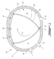
Fig. 2 , in a particular embodiment, theinternal combustion engine 10 is a rotary engine. AlthoughFig. 2 shows a Wankel engine, it is understood that therotary engine 10 may alternately have a different configuration than that of a Wankel engine. For example, in a particular embodiment, the rotary engine may be a single or eccentric type rotary engine in which the rotor rotates about a fixed center of rotation. For example, the rotary engine may be a sliding vane engine, such as described inUS patent No. 5,524,587 issued June 11, 1996 or inUS patent No. 5,522,356 issued June 4, 1996 . In another particular embodiment, the rotary engine may be an oscillatory rotating engine, including two or more rotors rotating at different angular velocities, causing the distance between portions of the rotors to vary and as such the chamber volume to change. In another particular embodiment, the rotary engine may be a planetary rotating engine having a different geometry than that of the Wankel engine, such as for example a planetary engine having an internal cavity with an epitrochoid profile defining three lobes and a rotor with four apex portions. Examples of such non-Wankel rotary engines are shown in Applicant'sU.S. application No. 14/796,185 filed January 25, 2013 - Still referring to
Fig. 2 , in the particular embodiment shown, therotary engine 10 comprises anouter body 12 having a plurality of rotor cavities 20 (only one of which is shown) each defined by axially-spacedend walls 14 and aperipheral wall 18 extending therebetween, with arotor 24 received in eachcavity 20. The inner surface of theperipheral wall 18 of eachcavity 20 has a profile defining two lobes, which is preferably an epitrochoid. - The
outer body 12 may be integral, containing all therotor cavities 20, or alternately be defined by a plurality of body portions (separate from one another or interconnected), for example each defining a respective one of thecavities 20 and receiving a respective one of therotors 24. - Each
rotor 24 is received within therespective cavity 20, with the geometrical axis of therotor 24 being offset from and parallel to the axis of theouter body 12. Eachrotor 24 has axially spaced end faces 26 adjacent to the outerbody end walls 14, and aperipheral face 28 extending therebetween. Theperipheral face 28 defines three circumferentially-spacedapex portions 30 and a generally triangular profile with outwardly arched sides. Theapex portions 30 are in sealing engagement with the inner surface ofperipheral wall 18 to form three rotating working orcombustion chambers 32 between theinner rotor 24 andouter body 12. A recess (not shown) is defined in theperipheral face 28 of therotor 24 between each pair ofadjacent apex portions 30, to form part of thecorresponding chamber 32. - The
combustion chambers 32 are sealed. Eachrotor apex portion 30 has anapex seal 52 extending from oneend face 26 to the other and protruding radially from theperipheral face 28. Eachapex seal 52 is biased radially outwardly against theperipheral wall 18 through a respective spring. An end seal 54 engages each end of eachapex seal 52, and is biased against therespective end wall 14 through a suitable spring. Eachend face 26 of therotor 24 has at least one arc-shaped face seal 60 running from eachapex portion 30 to eachadjacent apex portion 30, adjacent to but inwardly of the rotor periphery throughout its length. A spring urges eachface seal 60 axially outwardly so that theface seal 60 projects axially away from the adjacentrotor end face 26 into sealing engagement with theadjacent end wall 14 of the cavity. Eachface seal 60 is in sealing engagement with the end seal 54 adjacent each end thereof. - Although not shown, each
rotor 24 is journaled on an eccentric portion of a shaft and includes a phasing gear co-axial with the rotor axis, which is meshed with a fixed stator phasing gear secured to the outer body co-axially with the shaft. The shaft rotates eachrotor 24 and the meshed gears guide therotor 24 to perform orbital revolutions within the respectiveinternal cavity 20. The shaft rotates three times for each complete rotation of onerotor 24 as it moves around the respectiveinternal cavity 20. Oil seals are provided around the phasing gear to prevent leakage flow of lubricating oil radially outwardly thereof between the respectiverotor end face 26 and outerbody end wall 14. - During each rotation of the
rotor 24, eachchamber 32 varies in volumes and moves around theinternal cavity 20 to undergo cycles with each cycle including the four phases of intake, compression, expansion and exhaust, these phases being similar to the strokes in a reciprocating-type internal combustion engine having a four-stroke cycle. - For each
cavity 20, aprimary inlet port 40 is defined through one of the walls of thestator body 12 for admitting air in turn into each of thecombustion chambers 32. In the embodiment shown, theprimary inlet port 40 is a peripheral port defined as an opening through theperipheral wall 18. In another embodiment, theprimary inlet port 40 may have a different configuration, for example be defined through one of theend walls 14, with another primary inlet port being optionally defined in the other one of theend walls 14. Theprimary inlet port 40 is in fluid communication with the turbocharger compressor 19 (seeFig. 1 ), as will be further detailed below. Theprimary inlet port 40 is in fluid communication with eachcombustion chamber 32 during the intake phase thereof and a beginning of the compression phase thereof. As such, therotary engine 10 operates under the principle of the Miller cycle, with its volumetric compression ratio lower than its volumetric expansion ratio, and with theprimary inlet port 40 remaining open, i.e. in communication with thechamber 32, during the beginning of the compression phase. - For each
cavity 20, anexhaust port 44 is defined through one of the walls of thestator body 12 for discharge of the exhaust gases from thecombustion chambers 32. In the embodiment shown, theexhaust port 44 is a peripheral port defined as an opening through theperipheral wall 18. In another embodiment, theexhaust port 44 may have a different configuration, for example be defined through one of theend walls 14, with another exhaust port being optionally defined in the other one of theend walls 14. - For each
cavity 20, a secondary inlet port or purgeport 42 is also defined through one of the walls of thestator body 12 for admitting air in turn into each of thecombustion chambers 32. Thesecondary inlet port 42 is located rearwardly of theprimary inlet port 40 and forwardly of theexhaust port 44 relative to the direction R of the rotor revolution and rotation. In the embodiment shown, thesecondary inlet port 42 is a peripheral port defined as an opening through theperipheral wall 18. In another embodiment, thesecondary inlet port 42 may have a different configuration, for example be defined through one of theend walls 14, with another secondary inlet port being optionally defined in the other one of theend walls 14. Thesecondary inlet port 42 is also in fluid communication with the turbocharger compressor 19 (seeFig. 1 ), as will be further detailed below. Thesecondary inlet port 42 is in fluid communication with eachcombustion chamber 32 during a portion of its cycle; this portion may include a beginning of the intake phase and/or an end of the exhaust phase. - In the present specification including the claims, "intake phase" is intended to refer to the portion of the cycle during which the
chamber 32 is in communication with at least oneinlet port chamber 32 increases such as to draw air therein, while "compression phase" is intended to refer to the portion of the cycle between the intake phase and the ignition phase during which the volume of thechamber 32 decreases, starting at the point in the cycle where the maximum chamber volume is reached after intake, regardless if actual air compression occurs. For example, in a particular embodiment, compression may be inexistent or minimal during the beginning of the compression phase when theprimary inlet port 40 is open. - In use, through each rotation of the
rotor 24, eachchamber 32 is filled with compressed air through theprimary inlet port 40 and thesecondary inlet port 42 during its intake phase as its volume increases. The air is then further compressed as by reducing the volume of therotating chamber 32, with the beginning of the compression phase being performed with theprimary inlet port 40 still open, i.e. in communication with thechamber 32, theprimary inlet port 40 closing during the compression phase. Once the air is further compressed, near minimum volume of thechamber 32, the ignition phase occurs: the air is mixed with fuel from a fuel source 9 (seeFig. 1 ) and the resulting air-fuel mixture is ignited. In a particular embodiment, the fuel is heavy fuel e.g. diesel, kerosene (jet fuel), equivalent biofuel, etc. Alternately, the fuel may be any other adequate type of fuel suitable for injection as described, including non-heavy fuel such as for example gasoline or liquid hydrogen fuel. The fuel is delivered such that thechamber 32 is stratified with a rich fuel-air mixture near the ignition source and a leaner mixture elsewhere, thus providing a so-called stratified charge arrangement, and the fuel-air mixture may be ignited within the housing using any suitable ignition system known in the art. Therotary engine 10 may include a pilot subchamber (not shown) receiving the ignition system and a pilot injector injecting a portion of the fuel therein for ignition. - After ignition, the combustion gases expand and force the volume of the
chamber 32 to increase. The combustion or exhaust gases exit thechamber 32 through theexhaust port 44 during the exhaust phase. At the end of the exhaust phase, thechamber 32 may communicate with both thesecondary inlet port 42 and theexhaust port 44, and the air entering thechamber 32 through thesecondary inlet port 42 may be used to purge remaining exhaust gases from thechamber 32. - Referring to
Fig. 3 , a connection arrangement between the different cavities of therotary engine 10 is shown. In the embodiment shown, therotary engine 10 includes tworotor cavities 20a,b, each receiving a respective rotor 24 (not shown inFig. 3 ) and each having aprimary inlet port 40a,b and asecondary inlet port 42a,b in communication with the combustion chambers defined therein. - A
first conduit 62 provides for fluid communication between theprimary inlet port 40a of thefirst cavity 20a and the secondary inlet port 42b of the second cavity 20b. Asecond conduit 64 provides for fluid communication between theprimary inlet port 40b of the second cavity 20b and thesecondary inlet port 42a of thefirst cavity 20a. Aplenum 21 receives the compressed air from theturbocharger compressor 19, and the first andsecond conduits plenum 21. - The rotors are engaged to the shaft in an angularly offset manner. Each combustion chamber defined in the
first cavity 20a undergoes the beginning of its compression phase (i.e. the part of the compression phase where theprimary inlet port 40a communicates with the chamber) while a corresponding combustion chamber defined in the second cavity 20b undergoes at least part of the portion of its cycle in communication with its secondary inlet port 42b, which in a particular embodiment is at the beginning of its intake phase. As such, thefirst conduit 62 allows for the compressed air overflowing from theprimary inlet port 40a of thefirst cavity 20a during the beginning of its compression phase to be fed into the secondary inlet port 42b of the second cavity 20b, in a particular embodiment together with air from theplenum 21. - Similarly, each combustion chamber defined in the second cavity 20b undergoes the beginning of its compression phase (i.e. the part of the compression phase where the
primary inlet port 40b communicates with the chamber) while a corresponding combustion chamber defined in thefirst cavity 20a undergoes at least part of the portion of its cycle in communication with itssecondary inlet port 42a, which in a particular embodiment is at the beginning of its intake phase. As such, thesecond conduit 64 allows for the compressed air overflowing from theprimary inlet port 40b of the second cavity 20b during the beginning of its compression phase to be fed into thesecondary inlet port 42a of thefirst cavity 20a, in a particular embodiment together with air from theplenum 21. - In a rotary engine including more than two rotors, the rotor cavities may be connected in pairs, i.e. with the first and second conduits interconnecting the same rotor cavities, or connected with different rotor cavities, i.e. with the primary inlet port of a first rotor being connected to the secondary inlet port of a second rotor and the secondary inlet port of the first rotor being connected to the primary inlet port of a third rotor, based on the relative timing (angular offset) of the rotors.
- Referring to
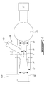
Fig. 4 , a particular embodiment for thefirst conduit 62 is shown, with thesecond conduit 64 being identical or similar thereto. Theconduit 62 is configured such as to form a Venturi to assist in the circulation of compressed air from theprimary inlet port 40a of thefirst cavity 20a to the secondary inlet port 42b of the second cavity 20b. In a particular embodiment, theconduit 62 has a circular cross-section. The conduit includes afirst segment 86 extending from theplenum 21. Asecond segment 88 extends from thefirst segment 86, and receives the connection with theprimary inlet port 40a of thefirst cavity 20a. Athird segment 90 extends from thesecond segment 88 and afourth segment 92 extends from thethird segment 90, with the third segment providing for a gradual transition between the different dimensions of the second andfourth segments fourth segment 92 receives the fluid communication with the secondary inlet port 42b of the second cavity 20b. - It can be seen that the
second segment 88 has a diameter D2 which is smaller than the diameter D1 of thefirst segment 86, and smaller than the diameter D3 of thefourth segment 92. In a particular embodiment, the ratio D1/D2 and the ratio D1/D3 are between 1 and 2. In another particular embodiment, the ratio D1/D2 and the ratio D1/D3 are from about 1.5 to about 1.8. Other values are also possible. - The
third segment 90 is tapered to define a progressive transition between the different diameters D2 and D3 of the second andfourth segments third segment 90 extends at an angle a from the outer wall of thefourth segment 92. In a particular embodiment, the angle α is from about 2.5° to about 7.5°. In another particular embodiment, the angle α is from about 3° to about 4°. Other values are also possible. - In the embodiment shown, the fluid communication between the
primary inlet port 40a and thesecond segment 88 is provided through aconduit portion 94 extending at an angle θ with respect to a perpendicular to a central axis C of thesecond segment 88. In a particular embodiment, the angle θ is from about -45° to about 60°. In another particular embodiment, the angle θ is from about 30° to about 60°. Other values are also possible. - In use, the compressed air is fed into the
combustion chambers 32 of therotary engine 10 in accordance with the following. The compressed air from theplenum 21 is fed through thefirst conduit 62 and into a combustion chamber of thefirst cavity 20a through itsprimary inlet port 40a as the chamber undergoes the intake phase, i.e. as its volume is increasing. Compressed air is also fed to the chamber through thesecond conduit 64 through itssecondary inlet port 40a during the beginning of the intake phase, and optionally the end of the exhaust phase. - After the intake phase, when the maximum volume of the chamber is reached, the compression phase begins and the volume of the chamber of the
first cavity 20a is reduced, at first while itsprimary inlet port 40a remains open. The air overflows out of thefirst cavity 20a through the openprimary inlet port 40a and into thefirst conduit 62, where it is fed to a combustion chamber of the second cavity 20b through its secondary inlet port 42b, with the chamber of the second cavity 20b being at the end of its exhaust phase or at the beginning of its intake phase. The chamber of the second cavity 20b undergoes the beginning of its intake phase, with its volume increasing, while the air from thefirst cavity 20a is received through its secondary inlet port 42b. Depending on the relative pressures, air may also be fed from theplenum 21 to the second cavity 20b through thefirst conduit 62 and secondary inlet port 42b. The communication between the combustion chamber of thefirst cavity 20a and itsprimary inlet port 40a is then closed, and the air within the combustion chamber of thefirst cavity 20a is further compressed during the remainder of the compression phase as the volume of the chamber is reduced to its minimum value. - The intake phase of the chamber of the second cavity 20b continues, and compressed air is fed from the
plenum 21 through thesecond conduit 64 and into the combustion chamber of the second cavity 20b through itsprimary inlet port 40b. After the intake phase, when the maximum volume of the chamber is reached, the compression phase begins and the volume of the chamber of the second cavity 20b reduces, at first while itsprimary inlet port 40b remains open. The air overflows out of the second cavity 20b through the openprimary inlet port 40b and into thesecond conduit 64, where it is fed to another combustion chamber of thefirst cavity 20a through itssecondary inlet port 42a, this chamber of thefirst cavity 20a being at the end of its exhaust phase or at the beginning of its intake phase. This other chamber of thefirst cavity 20a undergoes the beginning of its intake phase, with its volume increasing, while the air from the second cavity 20b is received through itssecondary inlet port 42a. Depending on the relative pressures, air may also be fed from theplenum 21 to thefirst cavity 20a through thesecond conduit 64 andsecondary inlet port 42a. The communication between the chamber of the second cavity 20b and itsprimary inlet port 40b is then closed, and the air within the combustion chamber of the second cavity 20b is further compressed until the end of its compression phase as the volume of the chamber is reduced to its minimum value. - Referring to
Fig. 5 , a similar connection arrangement between the different cavities of a reciprocating engine 110 is shown. In the embodiment shown, the reciprocating engine 110 includes fourcavities 120a,b,c,d each receiving arespective piston 124a,b,c,d to each define a single combustion chamber, and each having arespective inlet port 140a,b,c,d' and arespective exhaust port 144a,b,c,d in communication with the combustion chamber. A respective valve selectively allows and prevents the fluid communication between theinlet ports 140a,b,c,d and therespective cavity 120a,b,c,d and between theexhaust ports 144a,b,c,d and therespective cavity 120a,b,c,d. - A
plenum 121 receives the compressed air from theturbocharger compressor 19. First, second, third andfourth conduits - The
pistons 124a,b,c,d are engaged to the shaft in an angularly offset manner with eachcavity 120a,b,c,d undergoing the beginning of its compression phase with its inlet port open while another cavity undergoes part or all of its intake phase with its inlet port also open. In the embodiment shown, the pistons fire in the following order:first piston 124a,second piston 124b,fourth piston 124d andthird piston 124c. - As such, in the embodiment shown, first, second, third and
fourth inlet passages 170a,b,c,d extend from a respective one of theinlet ports 140a,b,c,d to theplenum 121. A firsttransverse passage 172 interconnects the first, second andfourth inlet passages 170a,b,d, while a secondtransverse passage 174 interconnects the first, third andfourth inlet passages 170a,c,d. A first one-way valve 176a allows a flow in the firsttransverse passage 172 from thefirst inlet passage 170a to thesecond inlet passage 170b while preventing the flow in the opposite direction. A second one-way valve 176b allows a flow in the firsttransverse passage 172 from thesecond inlet passage 170b to thefourth inlet passage 170d while preventing the flow in the opposite direction. A third one-way valve 176c allows a flow in the secondtransverse passage 174 from thefourth inlet passage 170d to thethird inlet passage 170c while preventing the flow in the opposite direction. A fourth one-way valve 176d allows a flow in the secondtransverse passage 174 from thethird inlet passage 170c to thefirst inlet passage 170a while preventing the flow in the opposite direction. - Thus, in the embodiment shown, when the
first cavity 120a is at the beginning of its compression phase with the valve of itsinlet port 140a remaining open, thesecond cavity 120b is in its intake phase, with the valve of itsinlet port 140b also being open. Afirst conduit 162 provides for fluid communication between thefirst inlet port 140a and thesecond inlet port 140b, as defined by thefirst inlet passage 170a, the portion of the firsttransverse passage 172 extending between the first andsecond inlet passages 170a,b including the first one-way valve 176a, and thesecond inlet passage 170b. The valves of the third andfourth inlet ports 140c,d are closed and prevent communication of thefirst conduit 162 with the third andfourth cavities 120c,d. - The
second cavity 120b then begins its compression phase with the valve of thesecond inlet port 140b remaining open, and thefourth cavity 120d is in its intake phase, with the valve of thefourth inlet port 140d also being open. Asecond conduit 164 provides for fluid communication between thesecond inlet port 140b and thefourth inlet port 140d, defined by thesecond inlet passage 170b, the portion of the firsttransverse passage 172 extending between the second andfourth inlet passages 170b,d including the second one-way valve 176b, and thefourth inlet passage 176d. The valves of the first andthird inlet ports 140a,c are closed and prevent communication of thesecond conduit 164 with the first andthird cavities 120a,c. - The
fourth cavity 120d then begins its compression phase with the valve of thefourth inlet port 140d remaining open, and thethird cavity 120c is in the intake phase, with the valve of thethird inlet port 140c also being open. Athird conduit 166 provides for fluid communication between thefourth inlet port 140d and thethird inlet port 140c, defined by thefourth inlet passage 170d, the portion of the secondtransverse passage 174 extending between the fourth andthird inlet passages 170d,c including the third one-way valve 176c, and thethird inlet passage 170c. The valves of the first andsecond inlet ports 140a,b are closed and prevent communication of thethird conduit 166 with the first andsecond cavities 120a,b. - The
third cavity 120c then begins its compression phase with the valve of thethird inlet port 140c remaining open, and thefirst cavity 120a is in the intake phase, with the valve of thefirst inlet port 140a also being open. Afourth conduit 168 provides for fluid communication between thethird inlet port 140c and thefirst inlet port 140a, defined by thethird inlet passage 170c, the portion of the secondtransverse passage 174 extending between the third andfirst inlet passages 170c,a including the fourth one-way valve 176d, and thefirst inlet passage 170a. The valves of the second andfourth inlet ports 140b,d are closed and prevent communication of thefourth conduit 168 with the second andfourth cavities 120b,d. - The
conduits plenum 121 through theinlet passages 170a,b,c,d. In a particular embodiment, theconduits - In an alternate embodiment, the
internal combustion engine 10, 110 is a rotary engine with a single inlet port for each cavity, and a communication similar to that described above for the reciprocating engine 110 is provided. An another embodiment, theinternal combustion engine 10, 110 is a reciprocating engine with a primary and a secondary inlet port for each cavity, and a communication similar to that described above for therotary engine 10 is provided. - In a particular embodiment, the
conduits cavity 20a,b, 120a,b,c,d at the beginning of the compression phase of each chamber into a chamber of anothercavity 20a,b, 120a,b,c,d simultaneously undergoing its intake phase allow for a reduction of the pressure losses which may otherwise be associated with the use of the Miller cycle in an internal combustion engine. - In a particular embodiment, the internal combustion engine 10,110 is a premix engine where the fuel is for example gasoline, and the fuel may be injected in the inlet port; in this case, the air circulated between the inlet ports may also include fuel mixed therewith.
- The above description is meant to be exemplary only, and one skilled in the art will recognize that changes may be made to the embodiments described without departing from the scope of the invention(s) disclosed. Modifications which fall within the scope of the present invention will be apparent to those skilled in the art, in light of a review of this disclosure, and such modifications are intended to fall within the appended claims.
Claims (14)
- An internal combustion engine (10) comprising:at least two rotatable bodies (24);an outer body (12) defining a respective internal cavity (20) for each of the bodies (24), each of the bodies (24) being sealingly and rotationally received within the respective internal cavity (20) to each define at least one combustion chamber (32) of variable volume undergoing a cycle defining successive phases of intake, compression, combustion and exhaust;at least one inlet port (40) for each respective internal cavity (20), the at least one inlet port (40) being in fluid communication with each of the at least one combustion chamber (32) of the respective internal cavity (20) at least during the intake phase thereof and a beginning portion of the compression phase thereof;at least one exhaust port (44) for each respective internal cavity (20), the at least one exhaust port (44) being in fluid communication with each of the at least one combustion chamber (32) of the respective internal cavity (20) during the exhaust phase thereof;a rotatable shaft, the bodies (24) being drivingly engaged to the shaft in an angularly offset manner with the beginning portion of the compression phase of the at least one combustion chamber (32) defined by each of the bodies (24) being simultaneous with at least a beginning of the intake phase of the at least one combustion chamber (32) defined by a different one of the bodies;a plenum (21) for receiving pressurized air; anda respective conduit (62,64) providing a fluid communication between the at least one inlet port (40) of the respective internal cavity (32) of each of the bodies and the at least one inlet port (40) of the respective internal cavity (20) of the different one of the bodies (24), each respective conduit (62,64) being in fluid communication with the plenum (21).
- The engine as defined in claim 1, wherein the at least one inlet port (40) for each respective internal cavity (20) includes a primary inlet port (40) in fluid communication with each of the at least one combustion chamber (32) during the intake phase thereof and the beginning of the compression phase thereof, and a secondary inlet port (42) in fluid communication with each of the at least one combustion chamber (32) during at least a beginning portion of the intake phase thereof, the respective conduit (62,64) providing a fluid communication between the primary inlet port (40) of each of the bodies (24) and the secondary inlet port (42) of the different one of the bodies (24).
- The engine as defined in claim 2, further comprising a turbocharger (17) having a compressor (19), the plenum (21) being in fluid communication with the compressor (19), wherein the secondary inlet port (42) is in fluid communication with each of the at least one combustion chamber (32) during a secondary portion of the cycle extending at most over the beginning of the intake phase and an end of the exhaust phase, the bodies (24) being drivingly engaged to the shaft such that the beginning portion of the compression phase of the at least one combustion chamber defined by each of the bodies (24) is simultaneous with at least part of the secondary portion of the cycle of the combustion chambers (32) defined by the different one of the bodies (24).
- The engine as defined in claim 3, wherein the at least one combustion chamber (32) defined by each of the bodies (24) is simultaneous with the beginning of the intake phase of the combustion chambers defined by the different one of the bodies (24).
- The engine as defined in claim 2, wherein the secondary inlet port (42) is also in fluid communication with each of the at least one combustion chamber (32) during an end of the exhaust phase thereof, the bodies (24) being drivingly engaged to the shaft with the beginning portion of the compression phase of the at least one combustion chamber (32) defined by each of the bodies (24) being simultaneous with at least part of the intake phase and with the end of the exhaust phase of the at least one combustion chamber (32) defined by the different one of the bodies (24).
- The engine as defined in any one of claims 2 to 5, wherein the bodies (24) include at least one pair of first and second rotors (24), with the respective conduit (62) of each first rotor (24) providing a fluid communication between the primary inlet port (40) of the first rotor (24) and the secondary inlet port (42) of the second rotor (24) of the same pair, and the respective conduit (64) of each second rotor (24) providing a fluid communication between the primary inlet port (40) of the second rotor (24) and the secondary inlet port (42) of the first rotor (24) of the same pair.
- The engine as defined in any one of claims 2 to 6, wherein each respective conduit (62,64) has first, second, third and fourth successive segments (86,88,90,92) each having a circular cross-section, the first segment (86) extending from the plenum (21), the fluid communication with the primary inlet port (40) being defined in the second segment (88), and the fluid communication with the secondary inlet port (42) being defined in the fourth segment (92), a diameter (D2) of the second segment (88) being smaller than a diameter (D1) of the first segment (86) and than a diameter (D3) of the fourth segment (92).
- The engine as defined in claim 7, wherein a ratio between the diameter (D1) of the first segment (86) and the diameter (D2) of the second segment (88) and a ratio between the diameter (D3) of the fourth segment (92) and the diameter (D2) of the second segment (88) are between 1 and 2.
- The engine as defined in claim 7 or 8, wherein the third segment (90) defined a tapered transition between the second and fourth segments (88,92), an outer wall of the third segment (90) forming an angle (α) of from about 2.5° to about 7.5° with an outer wall of the fourth segment (92).
- The engine as defined in any one of claims 6 to 8, wherein the fluid communication between the primary inlet port (40) and the second segment (88) is provided through a conduit (94) extending at an angle (θ) of from about -45° to about 60° with respect to a perpendicular to a central axis of the second segment (88).
- The engine as defined in any one of the preceding claims, wherein each respective internal cavity (20) is defined by two axially spaced apart end walls (14) and a peripheral wall (18) extending between the end walls (14), and each of the bodies (24) is a rotor body (24) rotatable within the respective internal cavity (20) in sealing engagement with the peripheral and end walls (18,14) defining a plurality of combustion chambers (32) of variable volume.
- The engine as defined in claim 11, wherein each internal cavity defines an epitrochoid shape with two lobes, and each rotor has three circumferentially spaced apex portions, and the plurality of combustion chambers includes three rotating chambers of variable volume, the rotor being engaged to an eccentric portion of the shaft to rotate and perform orbital revolutions within the cavity with each of the apex portions remaining in sealing engagement with the peripheral wall and separating the chambers.
- A method of feeding air to an internal combustion engine (10) having at least first and second internal cavities (20) each sealingly and rotationally receiving a respective rotor (24) therewithin, each of the internal cavities (20) having a primary inlet port (40) and a secondary inlet port (42) in fluid communication therewith, the method comprising:feeding compressed air to a combustion chamber (32) of the first cavity (20) through the primary inlet port (40) thereof while increasing a volume of the combustion chamber (32) until a maximum volume thereof is reached;while reducing a volume of the combustion chamber (32) from the maximum volume and at least in part while increasing a volume of a combustion chamber (32) of the second cavity (20), feeding compressed air from the combustion chamber (32) of the first cavity (20) through the primary inlet port (40) thereof into the combustion chamber (32) of the second cavity (20) through the secondary inlet port thereof;closing a communication between the primary inlet port (40) and the combustion chamber (32) of the first cavity (20) and further reducing the volume of the combustion chamber (32) of the first cavity (20) until a minimum volume thereof is reached; andfeeding compressed air to the combustion chamber (32) of the second cavity (20) through the primary inlet port (40) thereof while increasing the volume of the combustion chamber (32) of the second cavity (20) until a maximum volume thereof is reached.
- The method as defined in claim 13, further comprising:while reducing a volume of the combustion chamber (32) of the second cavity (20) from the maximum volume thereof and at least in part while increasing a volume of an additional combustion chamber (32) of the first cavity (20), feeding compressed air from the combustion chamber (32) of the second cavity (20) through the primary inlet port (40) thereof into the additional combustion chamber (32) of the first cavity (20) through the secondary inlet port thereof;closing a communication between the primary inlet port (40) and the combustion chamber (32) of the second cavity (20) and further reducing the volume of the combustion chamber (32) of the second cavity (20) until a minimum volume thereof is reached; andfeeding compressed air to the additional combustion chamber (32) of the first cavity (20) through the primary inlet port (40) thereof while increasing the volume of the additional combustion chamber (32) of the first cavity (20) until a maximum volume thereof is reached.
Priority Applications (1)
| Application Number | Priority Date | Filing Date | Title |
|---|---|---|---|
| PL14159403T PL2778342T3 (en) | 2013-03-13 | 2014-03-13 | Internal combustion engine with port communication |
Applications Claiming Priority (1)
| Application Number | Priority Date | Filing Date | Title |
|---|---|---|---|
| US13/799,965 US9181863B2 (en) | 2013-03-13 | 2013-03-13 | Internal combustion engine with port communication |
Publications (3)
| Publication Number | Publication Date |
|---|---|
| EP2778342A2 true EP2778342A2 (en) | 2014-09-17 |
| EP2778342A3 EP2778342A3 (en) | 2015-05-27 |
| EP2778342B1 EP2778342B1 (en) | 2017-10-25 |
Family
ID=50272447
Family Applications (1)
| Application Number | Title | Priority Date | Filing Date |
|---|---|---|---|
| EP14159403.6A Active EP2778342B1 (en) | 2013-03-13 | 2014-03-13 | Internal combustion engine with port communication |
Country Status (5)
| Country | Link |
|---|---|
| US (3) | US9181863B2 (en) |
| EP (1) | EP2778342B1 (en) |
| CA (1) | CA2844185C (en) |
| ES (1) | ES2654329T3 (en) |
| PL (1) | PL2778342T3 (en) |
Cited By (7)
| Publication number | Priority date | Publication date | Assignee | Title |
|---|---|---|---|---|
| EP3106643A1 (en) * | 2015-06-16 | 2016-12-21 | Pratt & Whitney Canada Corp. | Compound cycle engine |
| EP3106609A1 (en) * | 2015-06-16 | 2016-12-21 | Pratt & Whitney Canada Corp. | Compound engine assembly with exhaust pipe nozzle |
| EP3106644A1 (en) * | 2015-06-16 | 2016-12-21 | Pratt & Whitney Canada Corp. | Compound cycle engine |
| US9856789B2 (en) | 2012-07-20 | 2018-01-02 | Pratt & Whitney Canada Corp. | Compound cycle engine |
| US9926843B2 (en) | 2012-07-20 | 2018-03-27 | Pratt & Whitney Canada Corp. | Compound cycle engine |
| US10107195B2 (en) | 2012-07-20 | 2018-10-23 | Pratt & Whitney Canada Corp. | Compound cycle engine |
| US10196971B2 (en) | 2012-07-20 | 2019-02-05 | Pratt & Whitney Canada Corp. | Compound cycle engine |
Families Citing this family (1)
| Publication number | Priority date | Publication date | Assignee | Title |
|---|---|---|---|---|
| US9181863B2 (en) * | 2013-03-13 | 2015-11-10 | Pratt & Whitney Canada Corp. | Internal combustion engine with port communication |
Citations (6)
| Publication number | Priority date | Publication date | Assignee | Title |
|---|---|---|---|---|
| US5522356A (en) | 1992-09-04 | 1996-06-04 | Spread Spectrum | Method and apparatus for transferring heat energy from engine housing to expansion fluid employed in continuous combustion, pinned vane type, integrated rotary compressor-expander engine system |
| US5524587A (en) | 1995-03-03 | 1996-06-11 | Mallen Research Ltd. Partnership | Sliding vane engine |
| US7753036B2 (en) | 2007-07-02 | 2010-07-13 | United Technologies Corporation | Compound cycle rotary engine |
| US7775044B2 (en) | 2003-02-24 | 2010-08-17 | Pratt & Whitney Canada Corp. | Low volumetric compression ratio integrated turbo-compound rotary engine |
| US20140020381A1 (en) | 2012-07-20 | 2014-01-23 | Sébastien BOLDUC | Compound cycle engine |
| US20140020380A1 (en) | 2012-07-20 | 2014-01-23 | Jean Thomassin | Compound cycle engine |
Family Cites Families (20)
| Publication number | Priority date | Publication date | Assignee | Title |
|---|---|---|---|---|
| JPS5999034A (en) * | 1982-11-27 | 1984-06-07 | Mazda Motor Corp | Intake apparatus for rotary piston engine |
| JPS59101544A (en) * | 1982-12-02 | 1984-06-12 | Mazda Motor Corp | Suction device of rotary piston engine |
| JPS59101545A (en) * | 1982-12-02 | 1984-06-12 | Mazda Motor Corp | Suction device of rotary piston engine |
| JPS59218334A (en) * | 1983-05-25 | 1984-12-08 | Mazda Motor Corp | Suction device of rotary piston engine |
| GB2144489A (en) | 1983-08-03 | 1985-03-06 | Geoffrey Fawn | Rotary internal-combustion engine |
| US4627395A (en) * | 1984-04-19 | 1986-12-09 | Madza Motor Corporation | Intake system for rotary piston engines |
| JPS6282234A (en) | 1985-10-04 | 1987-04-15 | Mazda Motor Corp | Suction device for rotary piston engine |
| US4759324A (en) * | 1985-12-27 | 1988-07-26 | Mazda Motor Corporation | Intake system for rotary piston engine |
| JPH0656109B2 (en) * | 1985-12-27 | 1994-07-27 | マツダ株式会社 | Intake device for rotary piston engine |
| US4756284A (en) * | 1986-01-21 | 1988-07-12 | Mazda Motor Corporation | Intake system for internal combustion engine |
| JPH02233824A (en) * | 1989-03-08 | 1990-09-17 | Mazda Motor Corp | Intake system for engine |
| JPH10238354A (en) | 1996-12-27 | 1998-09-08 | Kanesaka Gijutsu Kenkyusho:Kk | Hybrid supercharged engine |
| JP2001055924A (en) | 1999-08-13 | 2001-02-27 | Miki Matsuda | Displacement increase device for miller cycle engine by secondary air supply method |
| JP3786066B2 (en) * | 2001-10-17 | 2006-06-14 | マツダ株式会社 | Engine intake system |
| US7347171B2 (en) | 2002-02-04 | 2008-03-25 | Caterpillar Inc. | Engine valve actuator providing Miller cycle benefits |
| US6651618B1 (en) | 2002-05-14 | 2003-11-25 | Caterpillar Inc | Air and fuel supply system for combustion engine |
| US6843231B1 (en) | 2003-12-19 | 2005-01-18 | Caterpillar Inc | Cylinder to cylinder balancing using intake valve actuation |
| JP4702103B2 (en) | 2006-03-01 | 2011-06-15 | 日産自動車株式会社 | Engine intake control method and intake control device |
| EP2065586A1 (en) | 2007-11-29 | 2009-06-03 | Perkins Engines Company Limited | Improved breathing for an internal combustion engine |
| US9181863B2 (en) * | 2013-03-13 | 2015-11-10 | Pratt & Whitney Canada Corp. | Internal combustion engine with port communication |
-
2013
- 2013-03-13 US US13/799,965 patent/US9181863B2/en active Active
-
2014
- 2014-02-27 CA CA2844185A patent/CA2844185C/en active Active
- 2014-03-13 ES ES14159403.6T patent/ES2654329T3/en active Active
- 2014-03-13 PL PL14159403T patent/PL2778342T3/en unknown
- 2014-03-13 EP EP14159403.6A patent/EP2778342B1/en active Active
-
2015
- 2015-10-20 US US14/887,611 patent/US9714604B2/en active Active
-
2017
- 2017-06-20 US US15/627,649 patent/US9896990B2/en active Active
Patent Citations (6)
| Publication number | Priority date | Publication date | Assignee | Title |
|---|---|---|---|---|
| US5522356A (en) | 1992-09-04 | 1996-06-04 | Spread Spectrum | Method and apparatus for transferring heat energy from engine housing to expansion fluid employed in continuous combustion, pinned vane type, integrated rotary compressor-expander engine system |
| US5524587A (en) | 1995-03-03 | 1996-06-11 | Mallen Research Ltd. Partnership | Sliding vane engine |
| US7775044B2 (en) | 2003-02-24 | 2010-08-17 | Pratt & Whitney Canada Corp. | Low volumetric compression ratio integrated turbo-compound rotary engine |
| US7753036B2 (en) | 2007-07-02 | 2010-07-13 | United Technologies Corporation | Compound cycle rotary engine |
| US20140020381A1 (en) | 2012-07-20 | 2014-01-23 | Sébastien BOLDUC | Compound cycle engine |
| US20140020380A1 (en) | 2012-07-20 | 2014-01-23 | Jean Thomassin | Compound cycle engine |
Cited By (14)
| Publication number | Priority date | Publication date | Assignee | Title |
|---|---|---|---|---|
| US10107195B2 (en) | 2012-07-20 | 2018-10-23 | Pratt & Whitney Canada Corp. | Compound cycle engine |
| US10968824B2 (en) | 2012-07-20 | 2021-04-06 | Pratt & Whitney Canada Corp. | Compound cycle engine |
| US10920662B2 (en) | 2012-07-20 | 2021-02-16 | Pratt & Whitney Canada Corp. | Compound cycle engine |
| US10196971B2 (en) | 2012-07-20 | 2019-02-05 | Pratt & Whitney Canada Corp. | Compound cycle engine |
| US9856789B2 (en) | 2012-07-20 | 2018-01-02 | Pratt & Whitney Canada Corp. | Compound cycle engine |
| US9926843B2 (en) | 2012-07-20 | 2018-03-27 | Pratt & Whitney Canada Corp. | Compound cycle engine |
| US9759128B2 (en) | 2015-06-16 | 2017-09-12 | Pratt & Whitney Canada Corp. | Compound engine assembly with exhaust pipe nozzle |
| CN107923309A (en) * | 2015-06-16 | 2018-04-17 | 普拉特 - 惠特尼加拿大公司 | Compound cycle engine |
| CN107923310A (en) * | 2015-06-16 | 2018-04-17 | 普拉特 - 惠特尼加拿大公司 | Compound cycle engine |
| EP3106643A1 (en) * | 2015-06-16 | 2016-12-21 | Pratt & Whitney Canada Corp. | Compound cycle engine |
| US10393014B2 (en) | 2015-06-16 | 2019-08-27 | Pratt & Whitney Canada Corp. | Engine assembly with exhaust pipe nozzle |
| CN107923310B (en) * | 2015-06-16 | 2020-03-31 | 普拉特-惠特尼加拿大公司 | Compound cycle engine |
| EP3106644A1 (en) * | 2015-06-16 | 2016-12-21 | Pratt & Whitney Canada Corp. | Compound cycle engine |
| EP3106609A1 (en) * | 2015-06-16 | 2016-12-21 | Pratt & Whitney Canada Corp. | Compound engine assembly with exhaust pipe nozzle |
Also Published As
| Publication number | Publication date |
|---|---|
| US20160040588A1 (en) | 2016-02-11 |
| EP2778342A3 (en) | 2015-05-27 |
| ES2654329T3 (en) | 2018-02-13 |
| US20140261292A1 (en) | 2014-09-18 |
| EP2778342B1 (en) | 2017-10-25 |
| CA2844185A1 (en) | 2014-09-13 |
| US20170284283A1 (en) | 2017-10-05 |
| US9181863B2 (en) | 2015-11-10 |
| PL2778342T3 (en) | 2018-05-30 |
| US9896990B2 (en) | 2018-02-20 |
| CA2844185C (en) | 2021-01-26 |
| US9714604B2 (en) | 2017-07-25 |
Similar Documents
| Publication | Publication Date | Title |
|---|---|---|
| US9896990B2 (en) | Internal combustion engine with port communication | |
| US11187146B2 (en) | Compound engine system with rotary engine | |
| US10138804B2 (en) | Rotary internal combustion engine | |
| US9926842B2 (en) | Rotary internal combustion engine with exhaust purge | |
| EP2778341B1 (en) | Internal combustion engine with common rail pilot and main injection | |
| EP2778367B1 (en) | Internal combustion engine with pilot and main injection | |
| EP3299607B1 (en) | Method of operating an engine having a pilot subchamber at partial load conditions | |
| US10393014B2 (en) | Engine assembly with exhaust pipe nozzle | |
| US10801401B2 (en) | Toroidal engine | |
| EP3628839B1 (en) | Engine assembly with multiplie rotary engine stacks | |
| EP2762675A1 (en) | Internal combustion rotary engine |
Legal Events
| Date | Code | Title | Description |
|---|---|---|---|
| 17P | Request for examination filed |
Effective date: 20140313 |
|
| AK | Designated contracting states |
Kind code of ref document: A2 Designated state(s): AL AT BE BG CH CY CZ DE DK EE ES FI FR GB GR HR HU IE IS IT LI LT LU LV MC MK MT NL NO PL PT RO RS SE SI SK SM TR |
|
| AX | Request for extension of the european patent |
Extension state: BA ME |
|
| PUAI | Public reference made under article 153(3) epc to a published international application that has entered the european phase |
Free format text: ORIGINAL CODE: 0009012 |
|
| PUAL | Search report despatched |
Free format text: ORIGINAL CODE: 0009013 |
|
| AK | Designated contracting states |
Kind code of ref document: A3 Designated state(s): AL AT BE BG CH CY CZ DE DK EE ES FI FR GB GR HR HU IE IS IT LI LT LU LV MC MK MT NL NO PL PT RO RS SE SI SK SM TR |
|
| AX | Request for extension of the european patent |
Extension state: BA ME |
|
| RIC1 | Information provided on ipc code assigned before grant |
Ipc: F02B 29/02 20060101ALI20150422BHEP Ipc: F01C 1/22 20060101AFI20150422BHEP |
|
| R17P | Request for examination filed (corrected) |
Effective date: 20151127 |
|
| RBV | Designated contracting states (corrected) |
Designated state(s): AL AT BE BG CH CY CZ DE DK EE ES FI FR GB GR HR HU IE IS IT LI LT LU LV MC MK MT NL NO PL PT RO RS SE SI SK SM TR |
|
| GRAP | Despatch of communication of intention to grant a patent |
Free format text: ORIGINAL CODE: EPIDOSNIGR1 |
|
| INTG | Intention to grant announced |
Effective date: 20170508 |
|
| GRAS | Grant fee paid |
Free format text: ORIGINAL CODE: EPIDOSNIGR3 |
|
| GRAA | (expected) grant |
Free format text: ORIGINAL CODE: 0009210 |
|
| AK | Designated contracting states |
Kind code of ref document: B1 Designated state(s): AL AT BE BG CH CY CZ DE DK EE ES FI FR GB GR HR HU IE IS IT LI LT LU LV MC MK MT NL NO PL PT RO RS SE SI SK SM TR |
|
| REG | Reference to a national code |
Ref country code: GB Ref legal event code: FG4D |
|
| REG | Reference to a national code |
Ref country code: CH Ref legal event code: EP |
|
| REG | Reference to a national code |
Ref country code: AT Ref legal event code: REF Ref document number: 940155 Country of ref document: AT Kind code of ref document: T Effective date: 20171115 |
|
| REG | Reference to a national code |
Ref country code: IE Ref legal event code: FG4D |
|
| REG | Reference to a national code |
Ref country code: DE Ref legal event code: R096 Ref document number: 602014016167 Country of ref document: DE |
|
| REG | Reference to a national code |
Ref country code: ES Ref legal event code: FG2A Ref document number: 2654329 Country of ref document: ES Kind code of ref document: T3 Effective date: 20180213 |
|
| REG | Reference to a national code |
Ref country code: FR Ref legal event code: PLFP Year of fee payment: 5 |
|
| REG | Reference to a national code |
Ref country code: NL Ref legal event code: MP Effective date: 20171025 |
|
| REG | Reference to a national code |
Ref country code: LT Ref legal event code: MG4D |
|
| PG25 | Lapsed in a contracting state [announced via postgrant information from national office to epo] |
Ref country code: NL Free format text: LAPSE BECAUSE OF FAILURE TO SUBMIT A TRANSLATION OF THE DESCRIPTION OR TO PAY THE FEE WITHIN THE PRESCRIBED TIME-LIMIT Effective date: 20171025 |
|
| PG25 | Lapsed in a contracting state [announced via postgrant information from national office to epo] |
Ref country code: LT Free format text: LAPSE BECAUSE OF FAILURE TO SUBMIT A TRANSLATION OF THE DESCRIPTION OR TO PAY THE FEE WITHIN THE PRESCRIBED TIME-LIMIT Effective date: 20171025 Ref country code: FI Free format text: LAPSE BECAUSE OF FAILURE TO SUBMIT A TRANSLATION OF THE DESCRIPTION OR TO PAY THE FEE WITHIN THE PRESCRIBED TIME-LIMIT Effective date: 20171025 Ref country code: NO Free format text: LAPSE BECAUSE OF FAILURE TO SUBMIT A TRANSLATION OF THE DESCRIPTION OR TO PAY THE FEE WITHIN THE PRESCRIBED TIME-LIMIT Effective date: 20180125 Ref country code: SE Free format text: LAPSE BECAUSE OF FAILURE TO SUBMIT A TRANSLATION OF THE DESCRIPTION OR TO PAY THE FEE WITHIN THE PRESCRIBED TIME-LIMIT Effective date: 20171025 |
|
| PG25 | Lapsed in a contracting state [announced via postgrant information from national office to epo] |
Ref country code: RS Free format text: LAPSE BECAUSE OF FAILURE TO SUBMIT A TRANSLATION OF THE DESCRIPTION OR TO PAY THE FEE WITHIN THE PRESCRIBED TIME-LIMIT Effective date: 20171025 Ref country code: BG Free format text: LAPSE BECAUSE OF FAILURE TO SUBMIT A TRANSLATION OF THE DESCRIPTION OR TO PAY THE FEE WITHIN THE PRESCRIBED TIME-LIMIT Effective date: 20180125 Ref country code: GR Free format text: LAPSE BECAUSE OF FAILURE TO SUBMIT A TRANSLATION OF THE DESCRIPTION OR TO PAY THE FEE WITHIN THE PRESCRIBED TIME-LIMIT Effective date: 20180126 Ref country code: LV Free format text: LAPSE BECAUSE OF FAILURE TO SUBMIT A TRANSLATION OF THE DESCRIPTION OR TO PAY THE FEE WITHIN THE PRESCRIBED TIME-LIMIT Effective date: 20171025 Ref country code: IS Free format text: LAPSE BECAUSE OF FAILURE TO SUBMIT A TRANSLATION OF THE DESCRIPTION OR TO PAY THE FEE WITHIN THE PRESCRIBED TIME-LIMIT Effective date: 20180225 Ref country code: HR Free format text: LAPSE BECAUSE OF FAILURE TO SUBMIT A TRANSLATION OF THE DESCRIPTION OR TO PAY THE FEE WITHIN THE PRESCRIBED TIME-LIMIT Effective date: 20171025 |
|
| REG | Reference to a national code |
Ref country code: DE Ref legal event code: R097 Ref document number: 602014016167 Country of ref document: DE |
|
| PG25 | Lapsed in a contracting state [announced via postgrant information from national office to epo] |
Ref country code: SK Free format text: LAPSE BECAUSE OF FAILURE TO SUBMIT A TRANSLATION OF THE DESCRIPTION OR TO PAY THE FEE WITHIN THE PRESCRIBED TIME-LIMIT Effective date: 20171025 Ref country code: DK Free format text: LAPSE BECAUSE OF FAILURE TO SUBMIT A TRANSLATION OF THE DESCRIPTION OR TO PAY THE FEE WITHIN THE PRESCRIBED TIME-LIMIT Effective date: 20171025 Ref country code: EE Free format text: LAPSE BECAUSE OF FAILURE TO SUBMIT A TRANSLATION OF THE DESCRIPTION OR TO PAY THE FEE WITHIN THE PRESCRIBED TIME-LIMIT Effective date: 20171025 Ref country code: CY Free format text: LAPSE BECAUSE OF FAILURE TO SUBMIT A TRANSLATION OF THE DESCRIPTION OR TO PAY THE FEE WITHIN THE PRESCRIBED TIME-LIMIT Effective date: 20171025 |
|
| PG25 | Lapsed in a contracting state [announced via postgrant information from national office to epo] |
Ref country code: RO Free format text: LAPSE BECAUSE OF FAILURE TO SUBMIT A TRANSLATION OF THE DESCRIPTION OR TO PAY THE FEE WITHIN THE PRESCRIBED TIME-LIMIT Effective date: 20171025 Ref country code: SM Free format text: LAPSE BECAUSE OF FAILURE TO SUBMIT A TRANSLATION OF THE DESCRIPTION OR TO PAY THE FEE WITHIN THE PRESCRIBED TIME-LIMIT Effective date: 20171025 |
|
| PLBE | No opposition filed within time limit |
Free format text: ORIGINAL CODE: 0009261 |
|
| STAA | Information on the status of an ep patent application or granted ep patent |
Free format text: STATUS: NO OPPOSITION FILED WITHIN TIME LIMIT |
|
| 26N | No opposition filed |
Effective date: 20180726 |
|
| PG25 | Lapsed in a contracting state [announced via postgrant information from national office to epo] |
Ref country code: MC Free format text: LAPSE BECAUSE OF FAILURE TO SUBMIT A TRANSLATION OF THE DESCRIPTION OR TO PAY THE FEE WITHIN THE PRESCRIBED TIME-LIMIT Effective date: 20171025 Ref country code: SI Free format text: LAPSE BECAUSE OF FAILURE TO SUBMIT A TRANSLATION OF THE DESCRIPTION OR TO PAY THE FEE WITHIN THE PRESCRIBED TIME-LIMIT Effective date: 20171025 |
|
| REG | Reference to a national code |
Ref country code: BE Ref legal event code: MM Effective date: 20180331 |
|
| REG | Reference to a national code |
Ref country code: IE Ref legal event code: MM4A |
|
| PG25 | Lapsed in a contracting state [announced via postgrant information from national office to epo] |
Ref country code: LU Free format text: LAPSE BECAUSE OF NON-PAYMENT OF DUE FEES Effective date: 20180313 |
|
| PG25 | Lapsed in a contracting state [announced via postgrant information from national office to epo] |
Ref country code: IE Free format text: LAPSE BECAUSE OF NON-PAYMENT OF DUE FEES Effective date: 20180313 |
|
| PG25 | Lapsed in a contracting state [announced via postgrant information from national office to epo] |
Ref country code: BE Free format text: LAPSE BECAUSE OF NON-PAYMENT OF DUE FEES Effective date: 20180331 |
|
| PG25 | Lapsed in a contracting state [announced via postgrant information from national office to epo] |
Ref country code: MT Free format text: LAPSE BECAUSE OF NON-PAYMENT OF DUE FEES Effective date: 20180313 |
|
| PG25 | Lapsed in a contracting state [announced via postgrant information from national office to epo] |
Ref country code: TR Free format text: LAPSE BECAUSE OF FAILURE TO SUBMIT A TRANSLATION OF THE DESCRIPTION OR TO PAY THE FEE WITHIN THE PRESCRIBED TIME-LIMIT Effective date: 20171025 |
|
| REG | Reference to a national code |
Ref country code: AT Ref legal event code: UEP Ref document number: 940155 Country of ref document: AT Kind code of ref document: T Effective date: 20171025 |
|
| PG25 | Lapsed in a contracting state [announced via postgrant information from national office to epo] |
Ref country code: HU Free format text: LAPSE BECAUSE OF FAILURE TO SUBMIT A TRANSLATION OF THE DESCRIPTION OR TO PAY THE FEE WITHIN THE PRESCRIBED TIME-LIMIT; INVALID AB INITIO Effective date: 20140313 Ref country code: PT Free format text: LAPSE BECAUSE OF FAILURE TO SUBMIT A TRANSLATION OF THE DESCRIPTION OR TO PAY THE FEE WITHIN THE PRESCRIBED TIME-LIMIT Effective date: 20171025 |
|
| PG25 | Lapsed in a contracting state [announced via postgrant information from national office to epo] |
Ref country code: MK Free format text: LAPSE BECAUSE OF NON-PAYMENT OF DUE FEES Effective date: 20171025 |
|
| PG25 | Lapsed in a contracting state [announced via postgrant information from national office to epo] |
Ref country code: AL Free format text: LAPSE BECAUSE OF FAILURE TO SUBMIT A TRANSLATION OF THE DESCRIPTION OR TO PAY THE FEE WITHIN THE PRESCRIBED TIME-LIMIT Effective date: 20171025 |
|
| PGFP | Annual fee paid to national office [announced via postgrant information from national office to epo] |
Ref country code: FR Payment date: 20230222 Year of fee payment: 10 Ref country code: CZ Payment date: 20230224 Year of fee payment: 10 Ref country code: AT Payment date: 20230222 Year of fee payment: 10 |
|
| PGFP | Annual fee paid to national office [announced via postgrant information from national office to epo] |
Ref country code: PL Payment date: 20230224 Year of fee payment: 10 Ref country code: IT Payment date: 20230221 Year of fee payment: 10 Ref country code: GB Payment date: 20230222 Year of fee payment: 10 Ref country code: DE Payment date: 20230221 Year of fee payment: 10 |
|
| P01 | Opt-out of the competence of the unified patent court (upc) registered |
Effective date: 20230530 |
|
| PGFP | Annual fee paid to national office [announced via postgrant information from national office to epo] |
Ref country code: ES Payment date: 20230403 Year of fee payment: 10 Ref country code: CH Payment date: 20230402 Year of fee payment: 10 |