EP3106583B1 - Bewehrungsstabverankerungsvorrichtung und verfahren zur verbindung davon an einen bewehrungsstab - Google Patents
Bewehrungsstabverankerungsvorrichtung und verfahren zur verbindung davon an einen bewehrungsstab Download PDFInfo
- Publication number
- EP3106583B1 EP3106583B1 EP15172152.9A EP15172152A EP3106583B1 EP 3106583 B1 EP3106583 B1 EP 3106583B1 EP 15172152 A EP15172152 A EP 15172152A EP 3106583 B1 EP3106583 B1 EP 3106583B1
- Authority
- EP
- European Patent Office
- Prior art keywords
- rebar
- barrel
- lid
- tapered
- anchorage device
- Prior art date
- Legal status (The legal status is an assumption and is not a legal conclusion. Google has not performed a legal analysis and makes no representation as to the accuracy of the status listed.)
- Active
Links
Images

Classifications
-
- E—FIXED CONSTRUCTIONS
- E04—BUILDING
- E04C—STRUCTURAL ELEMENTS; BUILDING MATERIALS
- E04C5/00—Reinforcing elements, e.g. for concrete; Auxiliary elements therefor
- E04C5/16—Auxiliary parts for reinforcements, e.g. connectors, spacers, stirrups
- E04C5/161—Protective caps for the ends of reinforcing bars
-
- E—FIXED CONSTRUCTIONS
- E04—BUILDING
- E04C—STRUCTURAL ELEMENTS; BUILDING MATERIALS
- E04C5/00—Reinforcing elements, e.g. for concrete; Auxiliary elements therefor
- E04C5/08—Members specially adapted to be used in prestressed constructions
- E04C5/12—Anchoring devices
- E04C5/122—Anchoring devices the tensile members are anchored by wedge-action
Definitions
- This invention relates to a mechanical anchorage device and to a method for connecting the device out in the field to the upstanding end of a rebar which may be embedded within and project from a section of concrete.
- the anchorage device forms a wide head on the rebar which will be covered with concrete to create one or more bearing surfaces and thereby enable the rebar to better withstand forces applied thereto through the concrete.
- Steel reinforcement bars i.e., rebars
- rebars Steel reinforcement bars
- a reinforced concrete structure e.g., a wall, panel, or the like
- the rebars can become prematurely separated from their concrete structure as a consequence of tensile loads applied to the rebar.
- a relatively wide head is often formed to establish a wide bearing surface at the end of each rebar.
- the headed end is then covered over with additional concrete.
- the end of the rebar may need to be cut and shortened in the field resulting in the preformed head being cut off the end.
- the end of each rebar is bent over to form a hook so as to increase the bearing area thereof.
- a plate has been welded to the end of the rebar.
- special equipment and/or tools may have to be transported into the field for post-installation treatment of the top ends of the rebars to better resist tensile loads. The requirement for special equipment and tools slows the construction project and increases cost.
- US 6,513,287 B1 discloses a method and apparatus for forming an anchorage of a post-tension system in which a tendon is positioned within a cavity of an anchor such that an end of the tendon extends outwardly of the cavity, a plurality of wedges are mechanically inserted within the cavity between the tendon and a wall of the cavity, and pressure is applied to an end of the tendon such that the tendon and the wedges are in interference-fit relationship with the cavity.
- a compression mechanism is used having a cylindrical member and a plunger extending in a channel of the cylindrical member. The wedges are attached to the cylindrical member and the cylindrical member is moved toward the cavity such that the wedges enter a space between the tendon and the wall of the cavity. The plunger applies a compressive force to the end of the tendon when the end of the tendon is in the channel of the cylindrical member.
- this invention relates to a mechanical anchor and to a method for connecting the anchor to the upstanding end of a steel reinforcement bar (i.e., a rebar) that projects from a concrete structure.
- a steel reinforcement bar i.e., a rebar
- the rebar anchor will be embedded within concrete so as to create a large bearing surface by which to enable the rebar to better withstand tensile forces such as those which are generated during an earthquake and applied to the rebar through the concrete.
- the rebar anchor includes a cylindrical barrel to surround the upstanding end of the rebar.
- a tapered bore runs longitudinally through the barrel within which to receive the end of the rebar.
- a disk-shaped resistance lid extends across the top of the barrel over the end of the rebar. The diameter of the lid may be greater than the diameter of the barrel to create a bearing surface below the lid.
- Located inside the tapered bore through the barrel is a tapered segmented jaw that is split into a plurality of wedges.
- the angle of the wedges matches the angle of the tapered bore.
- the wedges of the jaw are laid end-to-end and seated against the tapered bore.
- the wedges of the jaw are configured to surround and grip the rebar.
- the wedges are provided with teeth or sharp threads adapted to bite into and prevent a displacement of the rebar relative to the barrel of the rebar anchor.
- a helically-wound spring is positioned at the top of the tapered bore of the barrel to lie between the lid and the relatively wide top end of the tapered segmented jaw of the rebar anchor.
- a threaded bolt is moved through a correspondingly threaded bolt hole formed through the lid so as to apply an axial pushing force against the end of the rebar surrounded by the barrel. Accordingly, the rebar is pushed downwardly through the tapered bore and outwardly relative to the barrel to cause the segmented jaw to slide therealong so that the correspondingly angled wedges of the jaw close tightly around and are locked against the rebar, regardless of the diameter of the rebar.
- the rebar anchor is quickly and positively connected in surrounding engagement with the rebar out in the field to create a wide head thereon without requiring the use of special tools or machinery.
- the bottom of the cylindrical barrel creates an additional bearing surface by which to hold the rebar in place embedded in the concrete so as to be advantageously adapted to withstand tensile loads applied thereto.
- the rebar anchor of this invention does not add tension to or load the rebar to which it is connected.
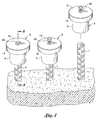
- FIG. 1 of the drawings shows a plurality of conventional rebars 1 (i.e., steel reinforcement bars) protruding from a concrete structure.
- the rebars 1 are particularly useful to reinforce the concrete structure so as to be able to withstand physical forces such as those generated by an earthquake. Any number of rebars 1 may be embedded within the concrete structure.
- FIG. 1 also shows a corresponding plurality of mechanical anchors 3 attached to upstanding ends of the embedded rebars 1.
- the rebar anchors 3 can be advantageously installed in the field, without requiring special tools or equipment, and without tensioning the rebars 1 to which the anchors 3 are attached.
- the rebar anchors 3 are adapted to be connected after the rebars 1 are already installed and embedded in concrete and without requiring that the upstanding ends thereof first be prepared (i.e., headed or bent). Once the post-installed rebar anchors 3 are attached to the upstanding ends of the rebars 1, the anchors and rebars are covered by and embedded within additional concrete.
- a (e.g., carbon steel) barrel 5 of the rebar anchor 3 is initially pushed or hammered onto the upstanding end of the rebar 1 so that the upstanding end 1 is surrounded by barrel 5.
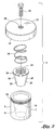
- the barrel 5 of anchor 3 has a cylindrical outside wall 7 and a tapered inside wall 9.
- a correspondingly tapered or angled inner bore 10 (best shown in FIG. 3 ) runs longitudinally through the barrel 5 for receipt therewithin of the rebar 1.
- a disk-shaped resistance lid 12 is connected over the upstanding end of rebar 1.
- the lid 12 is preferably welded to or rotated into surrounding mating engagement across the top of the barrel 5 of rebar anchor 3 so that the upstanding end of the rebar 1 moves upwardly towards the inside of the lid 12 when the barrel 5 is attached.
- the lid 12 has a peripheral lip 14 extending downwardly therefrom.
- the inside edge of the lip 14 of lid 12 is provided with a set of threads 16 running therearound.
- the top of the barrel 5 is provided with a complementary set of threads 18 running therearound.
- the threaded top of barrel 5 may be recessed with respect to the cylindrical outside wall 7 thereof at which the threaded lip 14 will be received when the lid 12 is rotated around the top of barrel 5 and the sets of threads 16 and 18 are mated to one another.
- the diameter of the lid 12 is greater than the diameter of the barrel 5.
- a tapered, segmented jaw 24 Located within the bore 10 running through the barrel 5 of rebar anchor 3 is a tapered, segmented jaw 24.
- the segmented jaw 24 is split into a plurality of independent wedges 26 that are disposed end-to-end one another and angled in order to be seated against the tapered inside wall 9 of barrel 5.
- a set of teeth or sharp threads 28 are formed inside the segmented jaw 24.
- the wedges 26 of the jaw 24 are configured to surround and grip (i.e., bite into) the rebar 1 to prevent a displacement thereof relative to barrel 5 regardless of the diameter of the rebar located in the bore 10 of barrel 5.
- a (e.g., steel or rubber) O-ring 30 is received by a peripheral groove formed in the wide (i.e., thickest) top ends of the wedges 26 of the jaw 24 so as to hold the wedges 26 together.
- a disk-shaped spring support 32 Laying on top of the O-ring 30 and surrounding the rebar 1 is a disk-shaped spring support 32.
- a helically-wound spring 34 is located above the jaw 24 at the top of the bore 10 of the barrel 5 of rebar anchor 3. The spring 34 is sized to surround the upstanding end of rebar 1 and positioned to lie between the inside of lid 12 and the spring support 32.
- a threaded bolt hole 38 is formed completely through the lid 12.
- a correspondingly threaded fastener e.g., a bolt 40
- the bolt 40 is axially advanced through the bolt hole 38 towards and into contact with the rebar 1 by means of a torque wrench or the like.
- the bolt 40 applies a downward pushing force directly against the top of the rebar 1 to force the rebar downwardly through the bore 10 and slightly outward from the barrel 5 of the rebar anchor 3.
- the helically-wound spring 34 is compressed by the lid 12 to exert a pushing force against the spring support 32 and thereby urge the wedges 26 of the tapered and segmented jaw 24 to slide downwardly along the tapered inside wall 9 of the bore 10 of the barrel 5.
- the segmented jaw 24 will automatically close around the rebar 1. More particularly, the angled wedges 26 of jaw 24 are forced radially inward towards rebar 1 by the matching tapered bore 10 so that the teeth 28 of wedges 26 bite into and are locked against the rebar.
- the rebar anchor 3 is quickly and positively connected to the top of the rebar 1 with minimal slippage to create a relatively wide head thereon after the rebar is already installed out in the field and without requiring the use of special tools or heading machines.
- the axial pushing force applied by the bolt 40 takes up any slack within the barrel 5 and thereby enables the rebar anchor 3 to be snugly held in surrounding engagement with the top of rebar 1.
- the combination bolt 40 and resistance lid 12 cooperate to eliminate internal movement (i.e., slippage) in both tension and compression to enable the post-installed anchor 3 to replicate a pre-installed rebar having an integral head that is formed by forging or welding.
- the anchor is covered by concrete.
- the relatively wide bottom of the barrel 5 of anchor 3 creates a primary bearing surface (designated 42 in FIG. 2 ) that will be embedded within the concrete.
- the aforementioned secondary bearing surface 20 is also created below the lip 14 and around the barrel 5.
- the rebar anchor 3 of this invention does not require the rebar to be stressed or tensioned to ensure a tight connection thereto.
- the rebar anchor 3 is capable of functioning under compressive and cyclic tension-compression loading.
Landscapes
- Engineering & Computer Science (AREA)
- Architecture (AREA)
- Civil Engineering (AREA)
- Structural Engineering (AREA)
- Reinforcement Elements For Buildings (AREA)
Claims (14)
- Verfahren zum Verbinden einer Verankerungsvorrichtung (3) an einem Stahlbewehrungsstab (1) mit ersten und gegenüberliegenden Enden und der Zug- und Druckbelastungen ausgesetzt ist, wobei die Verankerungsvorrichtung eine Trommel (5) mit einer Oberseite, einer Unterseite und einer verjüngten Bohrung (10), die in Längsrichtung zwischen der Oberseite und der Unterseite der Trommel (5) verläuft, einen Deckel (12), der mit der Trommel (5) verbunden ist und sich über die Oberseite dieser hinweg erstreckt, wobei der Deckel (12) eine darin gebildete, mit Gewinde versehene Öffnung (38) aufweist, die sich vollständig durch den Deckel (12) erstreckt, sowie eine verjüngte Backe (24) aufweist, die angeordnet ist in und durch die verjüngte Bohrung (10) der Trommel (5) gleit- bzw. verschiebbar ist, wobei das erste Ende des Bewehrungsstabs (1) durch die Trommel (5) der Verankerungsvorrichtung (3) umgeben ist, so dass der Bewehrungsstab (1) innerhalb der verjüngten Backe (24) aufgenommen wird, die innerhalb der Trommel (5) gelegen ist, und der Deckel (12) der Trommel (5) benachbart zu dem ersten Ende des Bewehrungsstab (1) liegt und dieses abdeckt, wobei das Verfahren die folgenden Schritte aufweist:Anordnen einer mit Gewinde versehenen Befestigungsvorrichtung (40) auf der Oberseite des Deckels (12) zur Aufnahme innerhalb der mit Gewinde versehenen Öffnung (38), die sich vollständig durch den Deckel (12) erstreckt, der mit der Oberseite der Trommel (5) verbunden ist, so dass die mit Gewinde versehene Befestigungsvorrichtung (40) in axialer Ausrichtung mit dem ersten Ende des Bewehrungsstabs (1) innerhalb der verjüngten Backe (24) liegt, die innerhalb des verjüngten Lochs (10) der Trommel (5) gelegen ist; undAnwenden einer Rotationskraft auf die mit Gewinde versehene Befestigungsvorrichtung (40) von oberhalb des Deckels (12) zum Vorschieben der mit Gewinde versehenen Befestigungsvorrichtung (40), und zwar vollständig durch die mit Gewinde versehene Öffnung (38), die sich vollständig durch den Deckel (12) erstreckt, in einen Ende-an-Ende-Kontakt mit dem ersten Ende des Bewehrungsstabs (1), um eine axiale Druckkraft direkt gegen das erste Ende anzuwenden und um dadurch zu bewirken, dass sich der Bewehrungsstab (1) durch die verjüngte Bohrung (10) der Trommel (5) bewegt und dass die verjüngte Backe (24) durch die verjüngte Bohrung (10) und in verriegelnden Eingriff mit dem ersten Ende des Bewehrungsstabs (1) gleitet, wodurch die Verankerungsvorrichtung (3) mit dem Bewehrungsstab (1) verbunden wird; undBedecken der Trommel (5) der Verankerungsvorrichtung (3) mit Beton, so dass die Trommel (5) eine Lager- bzw. Stützfläche auf dem Bewegungsstab (1) bildet, um den Bewehrungsstab (1) an der Stelle innerhalb des Betons zu halten.
- Verfahren gemäß Anspruch 1, wobei die mit Gewinde versehene Befestigungsvorrichtung (40) eine Gewindeschraube ist.
- Verfahren gemäß Anspruch 1, das den zusätzlichen Schritt des Einbettens des gegenüberliegenden Endes des Bewehrungsstabs (1) im Beton vor dem Schritt des Umgebens des ersten Endes des Bewehrungsstabs (1) mit der Trommel (5) der Verankerungsvorrichtung (3) aufweist.
- Verfahren gemäß Anspruch 1, wobei der Deckel (12) der Verankerungsvorrichtung (3) einen ersten Satz von Gewindegängen aufweist und die Oberseite der Trommel (5) der Verankerungsvorrichtung (3) durch einen zweiten Satz von Gewindegängen (18) umgeben ist, wobei das Verfahren den zusätzlichen Schritt des Drehens des ersten Satzes von Gewindegängen des Deckels (12) in zusammenpassenden Eingriff mit dem zweiten Satz von Gewindegängen (18) aufweist, die die Trommel (5) umgeben, um den Deckel (12) über die Oberseite der Trommel (5) hinweg zu verbinden.
- Verfahren gemäß Anspruch 1, wobei die Trommel (5) der Verankerungsvorrichtung (3) eine zylindrische Form aufweist und der Deckel (12) der Verankerungsvorrichtung (3), der über die Oberseite der Trommel (5) hinweg angebracht ist, eine Scheibenform aufweist, wobei der Deckel (12) einen längeren Durchmesser aufweist als der Durchmesser der Trommel (5), so dass die Lageroberfläche, die auf dem Bewehrungsstab (1) gebildet wird, unterhalb des Deckels (12) hergestellt wird.
- Verfahren gemäß Anspruch 1, wobei die verjüngte Backe (24), die innerhalb der verjüngten Bohrung (10) durch die Trommel (5) gelegen ist, eine Vielzahl von Keilen (26) aufweist, die einer neben dem anderen Ende-an-Ende liegen und wobei jede der Keile (26) einen Satz von Zähnen (28) aufweist, wobei die verjüngte Backe (24) durch die verjüngte Bohrung (10) gleitet, um die Vielzahl der Keile (26) der verjüngten Bohrung (24) zu veranlassen, gegen das erste Ende des Bewehrungsstabs (1) zu schließen, und die Zähne (28) der Keile (26) zu veranlassen, in den Bewehrungsstab (1) zu beißen, wodurch die Verankerungsvorrichtung (3) mit dem ersten Ende des Bewehrungsstabs (1) verbunden wird, und zwar ansprechend auf den Schritt des Vorschiebens der mit Gewinde versehenen Befestigungsvorrichtung (40) vollständig durch die mit Gewinde versehene Öffnung (38), die sich vollständig durch den Deckel (12) und in den Ende-an-Ende-Kontakt mit dem ersten Ende des Bewehrungsstabs (1) erstreckt, um eine axiale Druckkraft darauf anzuwenden.
- Verfahren gemäß Anspruch 6, wobei die Verankerungsvorrichtung (3) eine Feder (34) aufweist, wobei das Verfahren den zusätzlichen Schritt des Anordnens der Feder (34) innerhalb der verjüngten Bohrung (10) durch die Trommel (5) oben auf der verjüngten Backe (24) aufweist, so dass die Feder (34) die verjüngte Backe (24) zwingt, durch die verjüngte Bohrung (10) zu gleiten, und die Vielzahl der Keile (26) der verjüngten Backe (24) gegen das erste Ende des Bewehrungsstabs (1) zu schließen, wodurch die Zähne (28) der Keile (26) in den Bewehrungsstab (1) beißen, um die Verankerungsvorrichtung (3) mit dem ersten Ende des Bewehrungsstabs (1) zu verbinden.
- Kombination, die Folgendes aufweist:einen Stahlbewehrungsstab (1) mit einem ersten und einem gegenüberliegenden Ende, wobei das erste Ende des Bewehrungsstabs in Beton eingebettet werden soll; undeine Verankerungsvorrichtung (3), die mit dem ersten Ende des Bewehrungsstabs (1) verbunden werden soll, und zwar bevor das erste Ende innerhalb des Betons eingebettet wird und ohne Verspannen des Bewehrungsstabs (1), wobei die Verankerungsvorrichtung (3) Folgendes aufweist:eine Trommel (5) mit einer offenen Oberseite, einer offenen Unterseite und einer verjüngten Bohrung (10), die zwischen der Oberseite und der Unterseite von dieser verläuft, in die das erste Ende des Bewehrungsstabs (1) aufgenommen werden soll, damit die Trommel (5) den Bewehrungsstab (1) umgibt;eine verjüngte Backe (24) die innerhalb der verjüngten Bohrung (10) gelegen ist und durch diese durch die Trommel (5) verschiebbar ist, so dass die verjüngte Backe (24) das erste Ende des Bewehrungsstabs (1) innerhalb der verjüngten Bohrung (10) umgibt;einen Deckel (12), der über die offene Oberseite der Trommel (5) hinweg verbunden ist, um benachbart zu dem ersten Ende des Bewehrungsstabs (1) zu liegen und dieses abzudecken, wobei der Deckel (12) eine mit Gewinde versehen Öffnung (38) aufweist, die in diesem gebildet ist, die sich vollständig durch den Deckel (12) erstreckt; undeine mit Gewinde versehene Befestigungsvorrichtung (40), die auf eine darauf angewendete Drehkraft von oberhalb des Deckels (12) anspricht, so dass die mit Gewinde versehene Befestigungsvorrichtung (40) veranlasst wird, sich vollständig durch die mit Gewinde versehene Öffnung (38) zu bewegen, die sich vollständig durch den Deckel (12) erstreckt, der über die offene Oberseite der Trommel (5) hinweg und in einem Ende-an-Ende-Kontakt mit dem ersten Ende des Bewehrungsstabs (1) verbunden ist, um eine axiale Druckkraft auf das erste Ende anzubringen, so dass der Bewehrungsstab (1) veranlasst wird, sich axial durch die verjüngte Bohrung (10) der Trommel (5) zu bewegen, und um dadurch die verjüngte Backe (24) zu veranlassen durch die verjüngte Bohrung (10) und in einen verriegelnden Eingriff mit dem ersten Ende des Bewehrungsstabs (1) zu gleiten, wodurch die Verankerungsvorrichtung (3) mit dem ersten Ende verbunden ist, um eine Lageroberfläche zu bilden, um den Bewehrungsstab (1) an der Stelle zu halten, nachdem das erste Ende und die damit verbundene Verankerungsvorrichtung (3) innerhalb von Beton eingebettet sind.
- Kombination gemäß Anspruch 8, wobei die mit Gewinde versehene Befestigungsvorrichtung (40) eine Gewindeschraube ist, wobei die Gewindeschraube vollständig durch die mit Gewinde versehene Öffnung (38) gedreht wird, die sich vollständig durch den Deckel (12) erstreckt und in den Ende-an-Ende-Kontakt mit dem ersten Ende des Bewehrungsstabs (1) bewegt wird, um die axiale Druckkraft auf diesen anzuwenden.
- Kombination gemäß Anspruch 8, wobei der Deckel (12) einen ersten Satz von Gewindegängen aufweist und die Trommel (5) von einem zweiten Satz von Gewindegängen (18) umgeben ist, wobei der erste Satz von Gewindegängen des Deckels (12) in ineinanderpassenden Eingriff mit dem zweiten Satz von Gewindegängen (18) gedreht wird, die die Trommel (5) umgeben, um den Deckel (12) an der Oberseite der Trommel (5) zu verbinden, um das erste Ende des Bewehrungsstabs (1) abzudecken.
- Kombination gemäß Anspruch 8, wobei die Trommel (5) eine zylindrische Form aufweist und der Deckel (12), der über die offene Oberseite der Trommel (5) hinweg verbunden ist, eine Scheibenform aufweist, wobei der Deckel (12) einen längeren Durchmesser als der Durchmesser der Trommel (5) aufweist, so dass die Lageroberfläche um das erste Ende des Bewehrungsstabs (1) herum unterhalb des Deckels (12) erzeugt wird, nachdem das erste Ende und die damit verbundene Verankerungsvorrichtung (3) innerhalb des Betons eingebettet werden.
- Kombination gemäß Anspruch 8, wobei die verjüngte Backe (24), die innerhalb der verjüngten Bohrung (10) durch die Trommel (5) gelegen ist, eine Vielzahl von Keilen (26) aufweist, die einer neben dem anderen Ende-an-Ende liegen und wobei jeder der Keile (26) einen Satz von Zähnen (28) aufweist, wobei die verjüngte Backe (24) durch die verjüngte Bohrung gleitet, um die Vielzahl der Keile (26) der verjüngten Bohrung (24) zu veranlassen, gegen das erste Ende des Bewehrungsstabs (1) zu schließen, und um die Zähne (28) der Keile (26) zu veranlassen, in den Bewehrungsstab (1) zu beißen, wodurch die Verankerungsvorrichtung (3) mit dem ersten Ende des Bewehrungsstabs (1) verbunden wird, und zwar ansprechend auf die axiale Druckkraft, die durch die mit Gewinde versehene Befestigungsvorrichtung (40) auf das erste Ende angewendet wird.
- Kombination gemäß Anspruch 12, wobei die Verankerungsvorrichtung (3) ebenfalls eine Feder (34) aufweist, die innerhalb der verjüngten Bohrung durch die Trommel (5) gelegen ist, wobei die Feder (34) die verjüngte Backe (24) zwingt, durch die verjüngte Bohrung zu gleiten, und die Vielzahl der Keile (26) der verjüngten Backe (24) zwingt, gegen das erste Ende des Bewehrungsstabs (1) abzuschließen, wodurch die Zähne (28) der Keile (26) in den Bewehrungsstab (1) beißen, um die Verankerungsvorrichtung (3) mit dem ersten Ende zu verbinden.
- Kombination gemäß Anspruch 13, wobei das gegenüberliegende Ende des Bewehrungsstabs (1) in Beton eingebettet wird, und zwar bevor das erste Ende des Bewehrungsstabs (1) in Beton eingebettet wird.
Priority Applications (2)
| Application Number | Priority Date | Filing Date | Title |
|---|---|---|---|
| ES15172152.9T ES2672354T3 (es) | 2015-06-15 | 2015-06-15 | Dispositivo de anclaje con barras de refuerzo y procedimiento para conectar el mismo a una barra de refuerzo |
| EP15172152.9A EP3106583B1 (de) | 2015-06-15 | 2015-06-15 | Bewehrungsstabverankerungsvorrichtung und verfahren zur verbindung davon an einen bewehrungsstab |
Applications Claiming Priority (1)
| Application Number | Priority Date | Filing Date | Title |
|---|---|---|---|
| EP15172152.9A EP3106583B1 (de) | 2015-06-15 | 2015-06-15 | Bewehrungsstabverankerungsvorrichtung und verfahren zur verbindung davon an einen bewehrungsstab |
Publications (2)
| Publication Number | Publication Date |
|---|---|
| EP3106583A1 EP3106583A1 (de) | 2016-12-21 |
| EP3106583B1 true EP3106583B1 (de) | 2018-05-09 |
Family
ID=53433077
Family Applications (1)
| Application Number | Title | Priority Date | Filing Date |
|---|---|---|---|
| EP15172152.9A Active EP3106583B1 (de) | 2015-06-15 | 2015-06-15 | Bewehrungsstabverankerungsvorrichtung und verfahren zur verbindung davon an einen bewehrungsstab |
Country Status (2)
| Country | Link |
|---|---|
| EP (1) | EP3106583B1 (de) |
| ES (1) | ES2672354T3 (de) |
Families Citing this family (6)
| Publication number | Priority date | Publication date | Assignee | Title |
|---|---|---|---|---|
| CN109778613B (zh) * | 2019-03-01 | 2023-12-19 | 河间市银龙轨道有限公司 | 一种锚固板自动安装锁紧装置 |
| CN110185140B (zh) * | 2019-05-27 | 2024-05-14 | 广西建筑材料科学研究设计院有限公司 | 一种限位自锁、解锁及钢筋连接的预制混凝土柱对接全断面连接盒装置 |
| CN110359637B (zh) * | 2019-07-26 | 2021-11-12 | 陈城 | 一种螺纹钢接头 |
| CN114517562B (zh) * | 2020-11-20 | 2024-07-09 | 林恕如 | 钢筋锚定系统及方法 |
| CN112962867A (zh) * | 2021-02-08 | 2021-06-15 | 于洪强 | 钢筋连接装置 |
| CN113323272A (zh) * | 2021-06-07 | 2021-08-31 | 中建二局第四建筑工程有限公司 | 一种夹具式钢筋锚固板 |
Family Cites Families (2)
| Publication number | Priority date | Publication date | Assignee | Title |
|---|---|---|---|---|
| AT354029B (de) * | 1974-10-31 | 1979-12-10 | Vorspann Technik Gmbh | Verfahren zum vorverkeilen von spanngliedern in ankerkoerpern |
| US6513287B1 (en) * | 2000-09-05 | 2003-02-04 | Felix L. Sorkin | Apparatus for forming a dead-end anchorage of a post-tension system |
-
2015
- 2015-06-15 EP EP15172152.9A patent/EP3106583B1/de active Active
- 2015-06-15 ES ES15172152.9T patent/ES2672354T3/es active Active
Non-Patent Citations (1)
| Title |
|---|
| None * |
Also Published As
| Publication number | Publication date |
|---|---|
| EP3106583A1 (de) | 2016-12-21 |
| ES2672354T3 (es) | 2018-06-14 |
Similar Documents
| Publication | Publication Date | Title |
|---|---|---|
| US9091064B1 (en) | Rebar anchorage device and method for connecting same to a rebar | |
| EP3106583B1 (de) | Bewehrungsstabverankerungsvorrichtung und verfahren zur verbindung davon an einen bewehrungsstab | |
| US10711454B2 (en) | Cap for anchor of post-tension anchorage system | |
| US5630301A (en) | Anchorage assembly and method for post-tensioning in pre-stressed concrete structures | |
| US4173918A (en) | Roof bolt and the like | |
| JP5875767B2 (ja) | ロッド引張り装置、そのためのリム、それを用いた引張りシステム | |
| JP4295349B2 (ja) | 膨張アンカーおよびその設置方法 | |
| CA2987026C (en) | Wedge for post tensioning tendon | |
| US20090191007A1 (en) | Resin Mixing and Cable Tensioning Device and Assembly for Cable Bolts | |
| US8033760B2 (en) | Tension assembly | |
| NZ525344A (en) | Removable deep set drop-in anchor | |
| CN212376149U (zh) | 用于后浇带内连接无粘结预应力钢绞线的连接器 | |
| US10815665B2 (en) | Concrete anchor with retainer | |
| JP7601331B2 (ja) | ロックボルト及びその製造方法 | |
| KR101574663B1 (ko) | 말뚝압입장치 및 압입말뚝공법 | |
| EP3118386B1 (de) | Keil für nachträgliches spannen von bewehrungskabeln | |
| JP4446829B2 (ja) | 斜面安定化工法 | |
| JP7651107B2 (ja) | ロックボルト及びその製造方法 | |
| KR101598406B1 (ko) | 케이블 정착장치의 성능 개선 방법 및 이를 이용한 케이블 정착장치 | |
| KR102194774B1 (ko) | 인장부재 정착장치 | |
| JP2020041337A (ja) | テンドンの頭部定着構造 | |
| US20170114822A1 (en) | Counter-bored hex nut with captivated washer | |
| JP2022117016A (ja) | 二重式ナットを用いたグラウンドアンカー定着具 | |
| CN118531956A (zh) | 一种用于预应力楼板后续开洞保护的锚具及其锚固方法 | |
| KR20200055558A (ko) | 그라운드 앵커용 앵커헤드 및 이를 이용한 재긴장 시공방법 |
Legal Events
| Date | Code | Title | Description |
|---|---|---|---|
| PUAI | Public reference made under article 153(3) epc to a published international application that has entered the european phase |
Free format text: ORIGINAL CODE: 0009012 |
|
| AK | Designated contracting states |
Kind code of ref document: A1 Designated state(s): AL AT BE BG CH CY CZ DE DK EE ES FI FR GB GR HR HU IE IS IT LI LT LU LV MC MK MT NL NO PL PT RO RS SE SI SK SM TR |
|
| AX | Request for extension of the european patent |
Extension state: BA ME |
|
| 17P | Request for examination filed |
Effective date: 20170621 |
|
| RBV | Designated contracting states (corrected) |
Designated state(s): AL AT BE BG CH CY CZ DE DK EE ES FI FR GB GR HR HU IE IS IT LI LT LU LV MC MK MT NL NO PL PT RO RS SE SI SK SM TR |
|
| RIC1 | Information provided on ipc code assigned before grant |
Ipc: E04C 5/12 20060101ALN20171019BHEP Ipc: E04C 5/16 20060101AFI20171019BHEP |
|
| GRAP | Despatch of communication of intention to grant a patent |
Free format text: ORIGINAL CODE: EPIDOSNIGR1 |
|
| INTG | Intention to grant announced |
Effective date: 20171129 |
|
| GRAS | Grant fee paid |
Free format text: ORIGINAL CODE: EPIDOSNIGR3 |
|
| GRAA | (expected) grant |
Free format text: ORIGINAL CODE: 0009210 |
|
| AK | Designated contracting states |
Kind code of ref document: B1 Designated state(s): AL AT BE BG CH CY CZ DE DK EE ES FI FR GB GR HR HU IE IS IT LI LT LU LV MC MK MT NL NO PL PT RO RS SE SI SK SM TR |
|
| REG | Reference to a national code |
Ref country code: GB Ref legal event code: FG4D |
|
| REG | Reference to a national code |
Ref country code: CH Ref legal event code: EP Ref country code: AT Ref legal event code: REF Ref document number: 997683 Country of ref document: AT Kind code of ref document: T Effective date: 20180515 |
|
| REG | Reference to a national code |
Ref country code: NL Ref legal event code: FP Ref country code: IE Ref legal event code: FG4D |
|
| REG | Reference to a national code |
Ref country code: DE Ref legal event code: R096 Ref document number: 602015010863 Country of ref document: DE |
|
| REG | Reference to a national code |
Ref country code: FR Ref legal event code: PLFP Year of fee payment: 4 |
|
| REG | Reference to a national code |
Ref country code: ES Ref legal event code: FG2A Ref document number: 2672354 Country of ref document: ES Kind code of ref document: T3 Effective date: 20180614 |
|
| REG | Reference to a national code |
Ref country code: LT Ref legal event code: MG4D |
|
| PG25 | Lapsed in a contracting state [announced via postgrant information from national office to epo] |
Ref country code: LT Free format text: LAPSE BECAUSE OF FAILURE TO SUBMIT A TRANSLATION OF THE DESCRIPTION OR TO PAY THE FEE WITHIN THE PRESCRIBED TIME-LIMIT Effective date: 20180509 Ref country code: SE Free format text: LAPSE BECAUSE OF FAILURE TO SUBMIT A TRANSLATION OF THE DESCRIPTION OR TO PAY THE FEE WITHIN THE PRESCRIBED TIME-LIMIT Effective date: 20180509 Ref country code: NO Free format text: LAPSE BECAUSE OF FAILURE TO SUBMIT A TRANSLATION OF THE DESCRIPTION OR TO PAY THE FEE WITHIN THE PRESCRIBED TIME-LIMIT Effective date: 20180809 Ref country code: BG Free format text: LAPSE BECAUSE OF FAILURE TO SUBMIT A TRANSLATION OF THE DESCRIPTION OR TO PAY THE FEE WITHIN THE PRESCRIBED TIME-LIMIT Effective date: 20180809 Ref country code: FI Free format text: LAPSE BECAUSE OF FAILURE TO SUBMIT A TRANSLATION OF THE DESCRIPTION OR TO PAY THE FEE WITHIN THE PRESCRIBED TIME-LIMIT Effective date: 20180509 |
|
| PG25 | Lapsed in a contracting state [announced via postgrant information from national office to epo] |
Ref country code: GR Free format text: LAPSE BECAUSE OF FAILURE TO SUBMIT A TRANSLATION OF THE DESCRIPTION OR TO PAY THE FEE WITHIN THE PRESCRIBED TIME-LIMIT Effective date: 20180810 Ref country code: HR Free format text: LAPSE BECAUSE OF FAILURE TO SUBMIT A TRANSLATION OF THE DESCRIPTION OR TO PAY THE FEE WITHIN THE PRESCRIBED TIME-LIMIT Effective date: 20180509 Ref country code: LV Free format text: LAPSE BECAUSE OF FAILURE TO SUBMIT A TRANSLATION OF THE DESCRIPTION OR TO PAY THE FEE WITHIN THE PRESCRIBED TIME-LIMIT Effective date: 20180509 Ref country code: RS Free format text: LAPSE BECAUSE OF FAILURE TO SUBMIT A TRANSLATION OF THE DESCRIPTION OR TO PAY THE FEE WITHIN THE PRESCRIBED TIME-LIMIT Effective date: 20180509 |
|
| REG | Reference to a national code |
Ref country code: AT Ref legal event code: MK05 Ref document number: 997683 Country of ref document: AT Kind code of ref document: T Effective date: 20180509 |
|
| PG25 | Lapsed in a contracting state [announced via postgrant information from national office to epo] |
Ref country code: AT Free format text: LAPSE BECAUSE OF FAILURE TO SUBMIT A TRANSLATION OF THE DESCRIPTION OR TO PAY THE FEE WITHIN THE PRESCRIBED TIME-LIMIT Effective date: 20180509 Ref country code: DK Free format text: LAPSE BECAUSE OF FAILURE TO SUBMIT A TRANSLATION OF THE DESCRIPTION OR TO PAY THE FEE WITHIN THE PRESCRIBED TIME-LIMIT Effective date: 20180509 Ref country code: EE Free format text: LAPSE BECAUSE OF FAILURE TO SUBMIT A TRANSLATION OF THE DESCRIPTION OR TO PAY THE FEE WITHIN THE PRESCRIBED TIME-LIMIT Effective date: 20180509 Ref country code: CZ Free format text: LAPSE BECAUSE OF FAILURE TO SUBMIT A TRANSLATION OF THE DESCRIPTION OR TO PAY THE FEE WITHIN THE PRESCRIBED TIME-LIMIT Effective date: 20180509 Ref country code: RO Free format text: LAPSE BECAUSE OF FAILURE TO SUBMIT A TRANSLATION OF THE DESCRIPTION OR TO PAY THE FEE WITHIN THE PRESCRIBED TIME-LIMIT Effective date: 20180509 Ref country code: SK Free format text: LAPSE BECAUSE OF FAILURE TO SUBMIT A TRANSLATION OF THE DESCRIPTION OR TO PAY THE FEE WITHIN THE PRESCRIBED TIME-LIMIT Effective date: 20180509 Ref country code: PL Free format text: LAPSE BECAUSE OF FAILURE TO SUBMIT A TRANSLATION OF THE DESCRIPTION OR TO PAY THE FEE WITHIN THE PRESCRIBED TIME-LIMIT Effective date: 20180509 |
|
| REG | Reference to a national code |
Ref country code: CH Ref legal event code: PL |
|
| REG | Reference to a national code |
Ref country code: DE Ref legal event code: R097 Ref document number: 602015010863 Country of ref document: DE |
|
| PG25 | Lapsed in a contracting state [announced via postgrant information from national office to epo] |
Ref country code: IT Free format text: LAPSE BECAUSE OF FAILURE TO SUBMIT A TRANSLATION OF THE DESCRIPTION OR TO PAY THE FEE WITHIN THE PRESCRIBED TIME-LIMIT Effective date: 20180509 Ref country code: SM Free format text: LAPSE BECAUSE OF FAILURE TO SUBMIT A TRANSLATION OF THE DESCRIPTION OR TO PAY THE FEE WITHIN THE PRESCRIBED TIME-LIMIT Effective date: 20180509 |
|
| REG | Reference to a national code |
Ref country code: BE Ref legal event code: MM Effective date: 20180630 |
|
| PLBE | No opposition filed within time limit |
Free format text: ORIGINAL CODE: 0009261 |
|
| STAA | Information on the status of an ep patent application or granted ep patent |
Free format text: STATUS: NO OPPOSITION FILED WITHIN TIME LIMIT |
|
| REG | Reference to a national code |
Ref country code: IE Ref legal event code: MM4A |
|
| PG25 | Lapsed in a contracting state [announced via postgrant information from national office to epo] |
Ref country code: MC Free format text: LAPSE BECAUSE OF FAILURE TO SUBMIT A TRANSLATION OF THE DESCRIPTION OR TO PAY THE FEE WITHIN THE PRESCRIBED TIME-LIMIT Effective date: 20180509 Ref country code: LU Free format text: LAPSE BECAUSE OF NON-PAYMENT OF DUE FEES Effective date: 20180615 |
|
| 26N | No opposition filed |
Effective date: 20190212 |
|
| PG25 | Lapsed in a contracting state [announced via postgrant information from national office to epo] |
Ref country code: IE Free format text: LAPSE BECAUSE OF NON-PAYMENT OF DUE FEES Effective date: 20180615 Ref country code: LI Free format text: LAPSE BECAUSE OF NON-PAYMENT OF DUE FEES Effective date: 20180630 Ref country code: CH Free format text: LAPSE BECAUSE OF NON-PAYMENT OF DUE FEES Effective date: 20180630 |
|
| PG25 | Lapsed in a contracting state [announced via postgrant information from national office to epo] |
Ref country code: SI Free format text: LAPSE BECAUSE OF FAILURE TO SUBMIT A TRANSLATION OF THE DESCRIPTION OR TO PAY THE FEE WITHIN THE PRESCRIBED TIME-LIMIT Effective date: 20180509 Ref country code: BE Free format text: LAPSE BECAUSE OF NON-PAYMENT OF DUE FEES Effective date: 20180630 |
|
| PG25 | Lapsed in a contracting state [announced via postgrant information from national office to epo] |
Ref country code: AL Free format text: LAPSE BECAUSE OF FAILURE TO SUBMIT A TRANSLATION OF THE DESCRIPTION OR TO PAY THE FEE WITHIN THE PRESCRIBED TIME-LIMIT Effective date: 20180509 |
|
| PG25 | Lapsed in a contracting state [announced via postgrant information from national office to epo] |
Ref country code: MT Free format text: LAPSE BECAUSE OF NON-PAYMENT OF DUE FEES Effective date: 20180615 |
|
| PG25 | Lapsed in a contracting state [announced via postgrant information from national office to epo] |
Ref country code: TR Free format text: LAPSE BECAUSE OF FAILURE TO SUBMIT A TRANSLATION OF THE DESCRIPTION OR TO PAY THE FEE WITHIN THE PRESCRIBED TIME-LIMIT Effective date: 20180509 |
|
| PG25 | Lapsed in a contracting state [announced via postgrant information from national office to epo] |
Ref country code: PT Free format text: LAPSE BECAUSE OF FAILURE TO SUBMIT A TRANSLATION OF THE DESCRIPTION OR TO PAY THE FEE WITHIN THE PRESCRIBED TIME-LIMIT Effective date: 20180509 |
|
| PG25 | Lapsed in a contracting state [announced via postgrant information from national office to epo] |
Ref country code: MK Free format text: LAPSE BECAUSE OF NON-PAYMENT OF DUE FEES Effective date: 20180509 Ref country code: CY Free format text: LAPSE BECAUSE OF FAILURE TO SUBMIT A TRANSLATION OF THE DESCRIPTION OR TO PAY THE FEE WITHIN THE PRESCRIBED TIME-LIMIT Effective date: 20180509 Ref country code: HU Free format text: LAPSE BECAUSE OF FAILURE TO SUBMIT A TRANSLATION OF THE DESCRIPTION OR TO PAY THE FEE WITHIN THE PRESCRIBED TIME-LIMIT; INVALID AB INITIO Effective date: 20150615 |
|
| PG25 | Lapsed in a contracting state [announced via postgrant information from national office to epo] |
Ref country code: IS Free format text: LAPSE BECAUSE OF FAILURE TO SUBMIT A TRANSLATION OF THE DESCRIPTION OR TO PAY THE FEE WITHIN THE PRESCRIBED TIME-LIMIT Effective date: 20180909 |
|
| PGFP | Annual fee paid to national office [announced via postgrant information from national office to epo] |
Ref country code: DE Payment date: 20250625 Year of fee payment: 11 |
|
| PGFP | Annual fee paid to national office [announced via postgrant information from national office to epo] |
Ref country code: GB Payment date: 20250621 Year of fee payment: 11 |
|
| PGFP | Annual fee paid to national office [announced via postgrant information from national office to epo] |
Ref country code: NL Payment date: 20250627 Year of fee payment: 11 |
|
| PGFP | Annual fee paid to national office [announced via postgrant information from national office to epo] |
Ref country code: FR Payment date: 20250624 Year of fee payment: 11 |
|
| PGFP | Annual fee paid to national office [announced via postgrant information from national office to epo] |
Ref country code: ES Payment date: 20250703 Year of fee payment: 11 |