EP3106330A1 - Toit de vehicule comprenant un dispositif de toit mobile - Google Patents
Toit de vehicule comprenant un dispositif de toit mobile Download PDFInfo
- Publication number
- EP3106330A1 EP3106330A1 EP15172936.5A EP15172936A EP3106330A1 EP 3106330 A1 EP3106330 A1 EP 3106330A1 EP 15172936 A EP15172936 A EP 15172936A EP 3106330 A1 EP3106330 A1 EP 3106330A1
- Authority
- EP
- European Patent Office
- Prior art keywords
- roof
- vehicle
- covering element
- rear folding
- front spoiler
- Prior art date
- Legal status (The legal status is an assumption and is not a legal conclusion. Google has not performed a legal analysis and makes no representation as to the accuracy of the status listed.)
- Granted
Links
Images


Classifications
-
- B—PERFORMING OPERATIONS; TRANSPORTING
- B60—VEHICLES IN GENERAL
- B60J—WINDOWS, WINDSCREENS, NON-FIXED ROOFS, DOORS, OR SIMILAR DEVICES FOR VEHICLES; REMOVABLE EXTERNAL PROTECTIVE COVERINGS SPECIALLY ADAPTED FOR VEHICLES
- B60J7/00—Non-fixed roofs; Roofs with movable panels, e.g. rotary sunroofs
- B60J7/02—Non-fixed roofs; Roofs with movable panels, e.g. rotary sunroofs of sliding type, e.g. comprising guide shoes
- B60J7/06—Non-fixed roofs; Roofs with movable panels, e.g. rotary sunroofs of sliding type, e.g. comprising guide shoes with non-rigid element or elements
- B60J7/061—Non-fixed roofs; Roofs with movable panels, e.g. rotary sunroofs of sliding type, e.g. comprising guide shoes with non-rigid element or elements sliding and folding
-
- B—PERFORMING OPERATIONS; TRANSPORTING
- B60—VEHICLES IN GENERAL
- B60J—WINDOWS, WINDSCREENS, NON-FIXED ROOFS, DOORS, OR SIMILAR DEVICES FOR VEHICLES; REMOVABLE EXTERNAL PROTECTIVE COVERINGS SPECIALLY ADAPTED FOR VEHICLES
- B60J7/00—Non-fixed roofs; Roofs with movable panels, e.g. rotary sunroofs
- B60J7/02—Non-fixed roofs; Roofs with movable panels, e.g. rotary sunroofs of sliding type, e.g. comprising guide shoes
- B60J7/04—Non-fixed roofs; Roofs with movable panels, e.g. rotary sunroofs of sliding type, e.g. comprising guide shoes with rigid plate-like element or elements, e.g. open roofs with harmonica-type folding rigid panels
- B60J7/043—Sunroofs e.g. sliding above the roof
- B60J7/0435—Sunroofs e.g. sliding above the roof pivoting upwardly to vent mode and moving at the outside of the roof to fully open mode
Definitions
- the invention relates to the technical field of motor vehicle.
- the invention relates to a vehicle roof having a movable roof device for selectively closing and at least partially exposing a roof opening present in a roof surface of the vehicle, this movable roof device comprising a slidable front spoiler roof element and a slidable rear folding roof element.
- It also relates to a motor vehicle equipped with such a vehicle roof.
- Sliding roof devices for motor vehicle comprising a cover movable between a closed position, an open position and a tilted position are already known from the prior art.
- a cover is known as a “slidable front spoiler roof ".
- Some vehicles called “premium” vehicles are equipped not only with such a slidable front spoiler roof, but also with a “slidable rear folding roof ".
- Said spoiler roof extends substantially above the front seats of the vehicle, while said folding roof extends substantially above the rear seats of the vehicle.
- Twice roof elements can be closed. But it is also possible to tilt spoiler roof and to slide it rearwards.
- said rear roof can be moved rearwards and consequently, can be folded, only when it is pushed by the spoiler roof.
- the front passengers may be desirable for the front passengers to have the spoiler roof in a closed position, and the rear roof in an open position.
- the object of the present invention is to provide a vehicle roof of the type known by DE 3828062 , but whose functioning is simpler and done according to front and/or rear passengers' wishes.
- the invention relates to vehicle roof having a movable roof device for selectively closing and at least partially exposing a roof opening present in a roof surface of the vehicle, this movable roof device comprising a slidable front spoiler roof and a slidable rear folding roof, both of which being guided along longitudinal guide means, characterized in that said front spoiler roof and said rear folding roof are driven by separate and independent driving means.
- roof elements can be managed independently, according to the passengers' choice.
- said front spoiler roof is movable towards a position in which it is in contact with and covers said rear folding roof.
- the vehicle roof further comprises a covering element to cover the front spoiler roof and/or the rear folding roof with respect to a side facing the vehicle interior.
- the covering element is beneficial to prevent sunlight entering the vehicle interior passing the front spoiler roof. But additionally or alternatively, the covering element is useful to cover a bottom side of the rear folding roof panel which faces the vehicle interior.
- folding roofs comprise a foldable hood element and a plurality of guiding and folding sticks movably arranged along a guide rail.
- the guiding and folding sticks drive the hood element which gets folded and hence comprise a wavelike shape. Due to this shape gaps become apparent at the side edges of the hood element which causes undesirable noise generated by wind entering the vehicle interior in particular at high speed.
- the covering element contributes to reduce wind throb noise by covering the bottom side of the foldable roof and hence hinder wind entering the apparent gaps of the folded roof.
- a covering element comprises an aesthetic aspect by covering the mechanics such as guiding means of the folding roof and the gaps of the folded roof from a vehicle interior side.
- the foldable hood element of a folding roof comprises several flexible fabric cuttings arranged at both sides of the folding roof one facing the outside of the vehicle and one facing the vehicle interior.
- the covering element there is no need for fabric cuttings or a headlining of the hood element. This also contributes to reduce moving forces necessary to drive the rear folding roof.
- the covering element might be configured to completely cover the rear folding roof or additionally the front spoiler roof in a closed position.
- the covering element covers the hood element of the folding roof or the rear folding roof from a rear edge of the roof opening to a given position with respect to the longitudinal vehicle direction.
- the covering element is moveably arranged and allows for parallel movement with respect to movement of the rear folding roof and/or the front spoiler roof.
- the invention also relates to a motor vehicle equipped with such a vehicle roof.
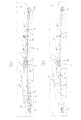
- FIG 1 we can see a roof opening 10 provided in the roof 11 of a vehicle 1.
- the roof opening 10 comprised two longitudinal sides 101, a front edge 102 and a rear edge 103.
- the words “outer” and “inner” are used by reference to the outer side of the roof opening and the inner side thereof (i.e. the void).
- the roof opening 10 is provided with a sliding roof device which comprises a slidable front spoiler 12 represented in solid line in its closed position (closure of the roof opening 10) and in dotted line in a tilted ventilation position. Further, spoiler 12 can be moved rearwards in the rear direction of the vehicle located on the right side of figure 1 .
- the spoiler 12 is preferably a transparent or translucent cover, especially a glass cover.
- the roof opening 10 is also provided with a rear folding roof 2 made of any impermeable and foldable material constituting a canvas.
- each of said front spoiler roof 12 and said rear folding roof 2 are driven by separate and independent driving means.
- These means are preferably electric motors M1, respectively M2. But additionally or alternatively, manual driving means is possible as well, for example realized by respective handle bars.
- the motors M1, M2 are attached to a fixed part of the roof 11, in the vicinity of the median plane of the opening 10. Said motors are linked to the driving means of spoiler roof 12 and folding roof 2 by cables C, as well known (see figure 2 , in dotted lines). These cables are wound on a reel (not represented here).
- these guiding means comprise a guide means assembly 3 which is longitudinally fixed on each side 101 of the roof opening 10.
- This guide assembly 3 has three guide pathways 30, 31 and 32.In other words, they constitute guiding rails 5.
- Bottom pathway 30 is positioned on the lower part of assembly 3. It has a cross section with a shape in "U" whose opening is directed upwardly.
- Intermediate pathway 31 is positioned above and in parallel with lower pathway 30. Both have the same length.
- the front end of intermediate pathway 31 consists in a guide ramp 310. Both have the same cross section with a shape in "U" whose opening is directed horizontally and in an outer direction. Said pathway 31 is offset from pathway 30 inwardly.
- Top pathway 32 begins at mid-length of intermediate pathway 31 and is positioned above and in parallel with the latter.
- the front end of pathway 32 consists in a guide ramp 320. It has the same shape and orientation as pathway 31.
- Means which permit to move slidable front spoiler 12 will be described hereafter with reference not only to figures 2 to 6 , but more specifically with reference to figures 7 and 8 .
- the means are generally identified by numeral reference 4.
- means 4 comprise, on each side of the roof opening 10: a slide body 40, and a main driving carriage 44 which supports a secondary carriage 45.
- the slide body 40 is preferably an L profile with a horizontal leg 41 (see figure 7 and 8 ) onto which the spoiler 12 is fixed on a sealing way by any appropriate means and a vertical plate 40 intended to be linked to carriages 44 and 45.
- said vertical plate 40 From the front F to the rear R, said vertical plate 40 has front part 42 with an elongated opening directed rearwards, which constitutes a cam track 43. Its opposite ends are closed and will have an abutment function as described below.
- This track has a front horizontal part followed by a rear downward part.
- the front bottom of part 42 is equipped with a sliding block 422.
- said vertical plate 40 is divided in to parallel flanges 420 which extend offset plate 40 and constitute together a "U"-shape bracket.
- Facing sides of said flanges are each equipped with a finger 421, whose function will be explicated hereafter.
- the rear part of the plate 40 has a tapered shape.
- Main carriage 44 is supported by bottom pathway 30 and has a shape which makes possible to move the carriage along the pathway.
- Secondary carriage 45 is fixed to the top of main carriage 44. It extends upwardly to form a vertical plate 46. Its front raised edge carries a rotating finger 47 directed and engaged inside cam track 43 of slide body 40. Its shape is designed in order to prevent its escape from cam track 43.
- Tracks 48 have a shape quite similar to the shape of track 43.
- cables C push each of main carriages 44, so fingers 47 and 421 are moved in opposite directions, while raising the spoiler 12 in the tilted position of figure 3 .
- the spoiler 12 can be moved to return to its closed position of figure 2 . Its displacement is made according to a kinematics which is opposite to the one described above. When considering figure 6 , it is shown that it is possible to have spoiler 12 in an intermediate position while the rear roof 2 is completely folded.
- the structure which permits to move said rear folding roof 2 comprises a front cross unit 7, linked to a connecting rod 6 and to a main carriage 5.
- Main carriage 5 has the shape of a reverse "U", the free end of its parallel branches being equipped with sliding blocks 50, which are engaged in intermediate pathway 31.
- This carriage is linked to said connecting rod 6, which comprises a pair of rotating fingers 60 engaged in top pathway 32, one of which (the front one) is also a rotating axle for the rod 6. Consequently, when the carriage 5 is moved rearwards, the front part of connecting rod 6 is raised.
- Said rod 6 is articulated around a transverse axle 73 linked to said front cross unit 7.
- This unit has a width which is equal to the width of the opening 10 in the roof 11 of the vehicle 1. It main function is to retain, in a tightly manner, the front end of folding roof 2.
- said unit 7 comprise a top flat surface 71 on which the front end of folding roof 2 is attached by any known means.
- unit 7 includes a support panel 70 which extends under surface 71.
- the support panel 70 has a front and horizontal plate 700 which extends beyond the front end of surface 71.
- This plate 700 supports two transverse seals 701 and 702. The first one receives the rear edge of spoiler 12 when it is in its closed position (see the left side of figure 9 ), while seal 702 ensures a perfect seal between panel 70 and folding roof 2.
- Said panel 70 has a rear edge in the shape of transverse angle 72, whose horizontal part support a pair of leaf springs 9, the free end of which consisting in a flat surface 90 on which folding roof is fixed.
- Unit 7 also incorporates a raising finger 73 which supports angle 72 when the folding roof is moved rearward. Consequently, unit 7 remains in a horizontal position, even when it is moved.
- pathway 32 is also engaged a free carriage 8 which is moved rearwards only when it is pushed by unit 7.
- Carriage 8 supports a flat surface 90 identical with the one already described and a pair of leaf springs 9, the free end of which consisting in a flat surface 90 on which folding roof is fixed.
- a pair of tensioning longitudinal straps (not shown here), equipped with a spring, adjust the tension of the folding roof 2. These straps are linked to the unit 7 and to the rear edge of the roof opening and extend below said roof 2.
- said roof has a "zigzag" shape, with folds between each leaf spring 9.
- said front spoiler roof 12 is movable towards a position in which it is in contact with said rear folding roof 2.
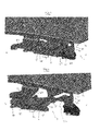
- FIGS. 11 , 12 and 13 illustrate the vehicle 1 and the vehicle roof 11 further comprising a covering element 22, which is moveably arranged with respect to the longitudinal vehicle direction D and which is configured to at least partially cover one side of the front spoiler roof 12 and/or the rear folding roof 2 facing a vehicle interior side.
- the roof opening 10 is bordered by a roof frame 100 of the vehicle roof 11.
- the roof frame 100 preferably comprises double-sided guide rails 33 extending in the longitudinal vehicle direction D.
- the guide rails 33 are part of the guide assembly 3.
- the guide rails 33 might by additional guide pathways or they are realized by the guide pathways 30, 31 and/or 32.
- the covering element 22 is guided by the separate double-sided guide rails 33 or alternatively it is guided by the guide pathways 30, 31 and/or 32 of the front spoiler roof 12 and the rear folding roof 2.
- the rear folding roof 2 comprises a hood element 20 with at least one flexible fabric cutting and is arranged on alternating folding and guiding sticks which are not shown in figures.
- the hood element 20 is mechanically coupled to the folding and guiding sticks.
- the folding and guiding sticks of the hood element 20 are moveably arranged in the guide rails 33 or the guided pathways 30, 31, 32 with respect to the longitudinal vehicle direction D.
- the guiding sticks may comprise sliding elements which enables sliding in the respective guide rails 33. In the region of the rear edge 103 of the roof opening 10 the hood element 20 is fixedly arranged.
- At least one guiding stick for example a front guiding stick of the rear folding roof 2 is coupled to driving means, for example the electrical rear motor M2 or to another additional electrical motor M3.
- driving means for example the electrical rear motor M2 or to another additional electrical motor M3.
- the hood element 20 and the rear folding roof 2 are foldable using the at least one guiding stick.
- the rear edge 103 of the roof opening 10 substantially extends in a direction perpendicular to the longitudinal vehicle direction D.
- the hood element 20 and the rear folding roof 2 are substantially strained parallel to the vehicle roof 11.
- the hood element 20 is driven by the front guiding stick rearwards wherein the further guiding and folding sticks are moved rearwards with respect to the longitudinal vehicle direction D.
- the folding sticks are tilted up vertically with respect to the guide rails 33 such that the rear folding roof 2 and the hood element 20 realize a folded state as shown in Figure 11 .
- the folded state shows one exemplary state of the rear folding roof 2 wherein the roof opening 10 is at least partially released.
- the covering element 22 is arranged at a bottom side of the front spoiler roof 12 and/or the rear folding roof 2 including the hood element 20 facing the vehicle interior for covering the mentioned components.
- the covering element 22 is realized as a roller blind which is windable by a winding shaft 23.
- the covering element 22 at least comprises one fabric cutting or the like to prevent light entering the vehicle interior and/or to realize a visual projection for covering the hood element 20 especially in a folded state.
- the winding shaft 23 is arranged in the region of the rear edge 103 of the roof opening 10 and is fixedly arranged.
- the winding shaft 23 may comprise a winding spring, which is not shown in figure, to generate a spring force to the roller blind 22 with respect to the longitudinal vehicle direction D.
- the covering element 22 is substantially flat in the region of the roof opening 10 and extends in transverse direction over the complete width B of the corresponding roof opening 10 between the guiding rails 33 of the guide assembly 3.
- a front edge 26 of the covering element 22 is located in the region of the front guiding stick of the hood element 20 of the rear folding roof 2 with respect to the longitudinal vehicle direction D.
- the covering element 22 extends from the rear edge 103 of the roof opening 10 to the front guiding stick of the hood element 20 and the rear folding roof 2.
- the covering element 22 extends from the rear edge 103 to a given position with respect to the longitudinal vehicle direction D and also covers the bottom side of the front spoiler roof 12 even to the front edge 102 of the roof opening 10 and the front spoiler roof 12.
- the covering element 22 is moveably coupled to driving means with respect to the longitudinal vehicle direction D and might be driven by the electrical motor M2 of the rear folding roof 2 or the additional electrical motor M3. Additionally or alternatively, the covering element 22 might be driveable manually using a handle bar of the covering element 22, for example.
- the covering element 22 may comprise one or more sliding elements arranged at side edges of the covering element 22 and arranged in the guide rails 33 or the guide pathways 30, 31, 32 of guiding means 3.
- the covering element 22 is shifted rearwards as well and is going to be wound up by the winding shaft 23.
- the covering element 22 and the hood element 20 are driven forwards with respect to the longitudinal vehicle direction D.
- shifting of the covering element 22 is synchronized with shifting of the hood element 20 and the rear folding roof 2.
- the position of the front edge 26 of the covering element 22 is ensured to be at the same height with respect to the hood element 20 and with respect to the longitudinal vehicle direction D.
- the covering element 22 permanently covers the bottom side of the hood element 20 in the region between the front guiding stick or a predetermined position of the front edge 26 of the covering element 22 and the rear edge 103 of the roof opening 10.
- the covering element 22 prevents a view of passengers on the bottom side of the rear folding roof 2 including the guiding and folding sticks and on the mechanics of the guide assembly 3 including the guide pathways 30, 31, 32 and possibly the guide rails 33.
- the covering element 22 further prevents the mechanics from being accessible by passengers, for example.
- a further advantage of the covering element 22 is the reduced wind throb noise due to the covered gaps of the folded rear folding roof 2 which are, in particular, apparent in side edges 27 of the hood element 20 because of its folded state.
- the driving means using the electrical motor M2 and/or M3 might be used.
- the driving means using the electrical motor M2 and/or M3 might be used.
- two exemplary embodiments of such a driving means are described.
- FIG. 12 schematically illustrates the roof opening 10.
- the driving means comprises two electrical motors M2 and M3 for driving the covering element 22 and the hood element 20 of the rear folding roof 2 separately.
- Each motor M2 and M3 is connected double-sided with the covering element 22 or the hood element 20 by respective driving cables C with respect to the longitudinal vehicle direction D.
- Electrical motor M2 is coupled to the front guiding stick 24 of the hood element 20.
- the other motor M3 is coupled to an arch 25 of the covering element 22 in the region of the front edge 26 of the covering element 22.
- Both motors M2 and M3 are electrically synchronized such that the synchronous motion of the covering element 22 and the hood element 20 as well as the rear folding roof 2 is enabled.
- motor M3 might be coupled to sliding elements of the covering element 22.
- Figure 13 illustrates an alternative embodiment of the driving means comprising only one electrical motor M2 which is coupled via driving cables C with the front guiding stick 24 of the hood element 20.
- the covering element 22 is mechanically coupled to the hood element 20 of the rear folding roof 2, in particular in the region of the front guiding stick 24.
- the front guide stick 24 of the foldable hood element 20 is connected to the arch 25 which is located in a free end portion in the region of the front edge 26 of the covering element 22.
- the free end portion of the covering element 22 is a region which faces the front edge 102 of the roof opening 10. In such a way, synchronous shifting of the hood element 20 and the covering element 22 is ensured. If motor M2 is now activated, shifting of the hood element 20 causes simultaneous shifting of the covering element 22.
- the covering element 22 and the hood element 20 of the rear folding roof 2 are connected with each other in another way, maybe using screw connections and/or firmly bonded connections. It is further possible that the covering element 22 is connected to the hood element 20 in other ways than using the arch 25 in the free end portion of the covering element 22.
- the covering element 22 might be designed as a plate-shaped roof element.
- shifting of the plate-shaped roof element might be synchronized to shifting of the hood element 20 of the rear folding roof 2.
- shifting of the covering element 22 and shifting of the rear folding roof 2 is not synchronized. Shifting of the covering element 22 might be realized independent from shifting of the rear folding roof 2 and the hood element 20 such that the covering element 22 even reaches the front spoiler roof 12 to cover the bottom side of the front spoiler roof 12 facing the vehicle interior.
- a motion of the covering element 22 is synchronized with a motion of the front spoiler roof 12 with respect to the longitudinal vehicle direction D. But it is also possible to realize shifting of the covering element 22 independently from shifting of the rear folding roof 2 and from shifting of the front spoiler roof 12 by electrical and/or manual driving means.
Priority Applications (1)
| Application Number | Priority Date | Filing Date | Title |
|---|---|---|---|
| EP15172936.5A EP3106330B1 (fr) | 2015-06-19 | 2015-06-19 | Toit de vehicule comprenant un dispositif de toit mobile |
Applications Claiming Priority (1)
| Application Number | Priority Date | Filing Date | Title |
|---|---|---|---|
| EP15172936.5A EP3106330B1 (fr) | 2015-06-19 | 2015-06-19 | Toit de vehicule comprenant un dispositif de toit mobile |
Publications (2)
| Publication Number | Publication Date |
|---|---|
| EP3106330A1 true EP3106330A1 (fr) | 2016-12-21 |
| EP3106330B1 EP3106330B1 (fr) | 2020-10-21 |
Family
ID=53442663
Family Applications (1)
| Application Number | Title | Priority Date | Filing Date |
|---|---|---|---|
| EP15172936.5A Active EP3106330B1 (fr) | 2015-06-19 | 2015-06-19 | Toit de vehicule comprenant un dispositif de toit mobile |
Country Status (1)
| Country | Link |
|---|---|
| EP (1) | EP3106330B1 (fr) |
Cited By (1)
| Publication number | Priority date | Publication date | Assignee | Title |
|---|---|---|---|---|
| CN112428801A (zh) * | 2020-11-30 | 2021-03-02 | 重庆长安汽车股份有限公司 | 汽车双顶篷切换装置 |
Citations (8)
| Publication number | Priority date | Publication date | Assignee | Title |
|---|---|---|---|---|
| US1831907A (en) * | 1930-02-01 | 1931-11-17 | Fred A Hart | Bus top |
| DE3828062A1 (de) | 1987-08-31 | 1989-03-09 | Webasto Ag Fahrzeugtechnik | Fahrzeugdach |
| US5169206A (en) * | 1989-02-10 | 1992-12-08 | Mazda Motor Corporation | Slidable roof control device for a motor vehicle |
| DE10318345A1 (de) * | 2002-04-18 | 2003-10-30 | Gerhard Semrau | Fahrzeugdach |
| US20050280291A1 (en) * | 2004-06-17 | 2005-12-22 | Storc Robert G | Automotive vehicle open air system |
| DE102004032627A1 (de) * | 2004-07-05 | 2006-02-16 | Wilhelm Karmann Gmbh | Kraftfahrzeug mit zumindest einem öffnungsfähigen Dachteil |
| DE102005043339A1 (de) * | 2005-08-09 | 2007-04-26 | Webasto Ag | Faltbares Verdeck |
| FR2983130A1 (fr) | 2011-11-28 | 2013-05-31 | Webasto Systemes Carrosserie | Mecanisme de fermeture d'un toit ouvrant en toile |
-
2015
- 2015-06-19 EP EP15172936.5A patent/EP3106330B1/fr active Active
Patent Citations (8)
| Publication number | Priority date | Publication date | Assignee | Title |
|---|---|---|---|---|
| US1831907A (en) * | 1930-02-01 | 1931-11-17 | Fred A Hart | Bus top |
| DE3828062A1 (de) | 1987-08-31 | 1989-03-09 | Webasto Ag Fahrzeugtechnik | Fahrzeugdach |
| US5169206A (en) * | 1989-02-10 | 1992-12-08 | Mazda Motor Corporation | Slidable roof control device for a motor vehicle |
| DE10318345A1 (de) * | 2002-04-18 | 2003-10-30 | Gerhard Semrau | Fahrzeugdach |
| US20050280291A1 (en) * | 2004-06-17 | 2005-12-22 | Storc Robert G | Automotive vehicle open air system |
| DE102004032627A1 (de) * | 2004-07-05 | 2006-02-16 | Wilhelm Karmann Gmbh | Kraftfahrzeug mit zumindest einem öffnungsfähigen Dachteil |
| DE102005043339A1 (de) * | 2005-08-09 | 2007-04-26 | Webasto Ag | Faltbares Verdeck |
| FR2983130A1 (fr) | 2011-11-28 | 2013-05-31 | Webasto Systemes Carrosserie | Mecanisme de fermeture d'un toit ouvrant en toile |
Cited By (2)
| Publication number | Priority date | Publication date | Assignee | Title |
|---|---|---|---|---|
| CN112428801A (zh) * | 2020-11-30 | 2021-03-02 | 重庆长安汽车股份有限公司 | 汽车双顶篷切换装置 |
| CN112428801B (zh) * | 2020-11-30 | 2023-03-17 | 重庆长安汽车股份有限公司 | 汽车双顶篷切换装置 |
Also Published As
| Publication number | Publication date |
|---|---|
| EP3106330B1 (fr) | 2020-10-21 |
Similar Documents
| Publication | Publication Date | Title |
|---|---|---|
| US6520569B2 (en) | Sunshade arrangement for a transparent motor vehicle part and motor vehicle roof with sunshade arrangement | |
| DE102009058293B4 (de) | Schutzvorrichtung für einen Fahrzeuginnenraum | |
| US20140175827A1 (en) | Motor vehicle body | |
| US6527337B2 (en) | Sliding roof cover of a motor vehicle roof and a motor vehicle roof with movable sliding roof covers | |
| US9114689B2 (en) | Side panel of a cover on a vehicle roof | |
| WO2010063312A1 (fr) | Ensemble pare-soleil et construction de toit ouvrant équipée de celui-ci | |
| EP1129871B1 (fr) | Dispositif de store de fenêtre pour fenêtres de véhicules | |
| US6499793B2 (en) | Folding for a convertible vehicle | |
| DE10140239A1 (de) | Sonnenrollovorrichtung für ein Fahrzeugdach | |
| US20160107514A1 (en) | Drive system for a movable roof part of a motor vehicle roof module | |
| JP4803409B2 (ja) | 開放可能な車両ルーフの移動可能なルーフ部 | |
| US9090149B1 (en) | Convertible system for a vehicle | |
| KR102291572B1 (ko) | 자동차용 차양 시스템 | |
| EP3106330B1 (fr) | Toit de vehicule comprenant un dispositif de toit mobile | |
| US20150266361A1 (en) | Vehicle roof having two lid members | |
| US7780220B2 (en) | Shade providing apparatus for vehicle | |
| US10399416B2 (en) | Sliding roof system for a motor vehicle | |
| US20070090664A1 (en) | Hardtop vehicle roof with external roof kinematic system | |
| US20190126837A1 (en) | System for covering a motor-vehicle luggage compartment | |
| US6419309B1 (en) | Open roof construction for a vehicle | |
| US7229126B2 (en) | Motor vehicle roof with two openable covers | |
| US8333426B2 (en) | Rise up panoramic roof for a vehicle | |
| US7416246B2 (en) | Motor vehicle with at least two movable parts | |
| EP2634025B1 (fr) | Véhicule automobile doté d'une ouverture de toit | |
| US10266042B2 (en) | Convertible vehicle having a cover for a linkage exit opening |
Legal Events
| Date | Code | Title | Description |
|---|---|---|---|
| PUAI | Public reference made under article 153(3) epc to a published international application that has entered the european phase |
Free format text: ORIGINAL CODE: 0009012 |
|
| STAA | Information on the status of an ep patent application or granted ep patent |
Free format text: STATUS: THE APPLICATION HAS BEEN PUBLISHED |
|
| AK | Designated contracting states |
Kind code of ref document: A1 Designated state(s): AL AT BE BG CH CY CZ DE DK EE ES FI FR GB GR HR HU IE IS IT LI LT LU LV MC MK MT NL NO PL PT RO RS SE SI SK SM TR |
|
| AX | Request for extension of the european patent |
Extension state: BA ME |
|
| STAA | Information on the status of an ep patent application or granted ep patent |
Free format text: STATUS: REQUEST FOR EXAMINATION WAS MADE |
|
| 17P | Request for examination filed |
Effective date: 20170602 |
|
| RBV | Designated contracting states (corrected) |
Designated state(s): AL AT BE BG CH CY CZ DE DK EE ES FI FR GB GR HR HU IE IS IT LI LT LU LV MC MK MT NL NO PL PT RO RS SE SI SK SM TR |
|
| STAA | Information on the status of an ep patent application or granted ep patent |
Free format text: STATUS: EXAMINATION IS IN PROGRESS |
|
| 17Q | First examination report despatched |
Effective date: 20191001 |
|
| GRAP | Despatch of communication of intention to grant a patent |
Free format text: ORIGINAL CODE: EPIDOSNIGR1 |
|
| STAA | Information on the status of an ep patent application or granted ep patent |
Free format text: STATUS: GRANT OF PATENT IS INTENDED |
|
| INTG | Intention to grant announced |
Effective date: 20200514 |
|
| GRAS | Grant fee paid |
Free format text: ORIGINAL CODE: EPIDOSNIGR3 |
|
| GRAA | (expected) grant |
Free format text: ORIGINAL CODE: 0009210 |
|
| STAA | Information on the status of an ep patent application or granted ep patent |
Free format text: STATUS: THE PATENT HAS BEEN GRANTED |
|
| AK | Designated contracting states |
Kind code of ref document: B1 Designated state(s): AL AT BE BG CH CY CZ DE DK EE ES FI FR GB GR HR HU IE IS IT LI LT LU LV MC MK MT NL NO PL PT RO RS SE SI SK SM TR |
|
| REG | Reference to a national code |
Ref country code: GB Ref legal event code: FG4D |
|
| REG | Reference to a national code |
Ref country code: CH Ref legal event code: EP |
|
| REG | Reference to a national code |
Ref country code: DE Ref legal event code: R096 Ref document number: 602015060698 Country of ref document: DE |
|
| REG | Reference to a national code |
Ref country code: IE Ref legal event code: FG4D |
|
| REG | Reference to a national code |
Ref country code: AT Ref legal event code: REF Ref document number: 1325485 Country of ref document: AT Kind code of ref document: T Effective date: 20201115 |
|
| REG | Reference to a national code |
Ref country code: AT Ref legal event code: MK05 Ref document number: 1325485 Country of ref document: AT Kind code of ref document: T Effective date: 20201021 |
|
| REG | Reference to a national code |
Ref country code: NL Ref legal event code: MP Effective date: 20201021 |
|
| PG25 | Lapsed in a contracting state [announced via postgrant information from national office to epo] |
Ref country code: FI Free format text: LAPSE BECAUSE OF FAILURE TO SUBMIT A TRANSLATION OF THE DESCRIPTION OR TO PAY THE FEE WITHIN THE PRESCRIBED TIME-LIMIT Effective date: 20201021 Ref country code: RS Free format text: LAPSE BECAUSE OF FAILURE TO SUBMIT A TRANSLATION OF THE DESCRIPTION OR TO PAY THE FEE WITHIN THE PRESCRIBED TIME-LIMIT Effective date: 20201021 Ref country code: PT Free format text: LAPSE BECAUSE OF FAILURE TO SUBMIT A TRANSLATION OF THE DESCRIPTION OR TO PAY THE FEE WITHIN THE PRESCRIBED TIME-LIMIT Effective date: 20210222 Ref country code: NO Free format text: LAPSE BECAUSE OF FAILURE TO SUBMIT A TRANSLATION OF THE DESCRIPTION OR TO PAY THE FEE WITHIN THE PRESCRIBED TIME-LIMIT Effective date: 20210121 Ref country code: NL Free format text: LAPSE BECAUSE OF FAILURE TO SUBMIT A TRANSLATION OF THE DESCRIPTION OR TO PAY THE FEE WITHIN THE PRESCRIBED TIME-LIMIT Effective date: 20201021 Ref country code: GR Free format text: LAPSE BECAUSE OF FAILURE TO SUBMIT A TRANSLATION OF THE DESCRIPTION OR TO PAY THE FEE WITHIN THE PRESCRIBED TIME-LIMIT Effective date: 20210122 |
|
| REG | Reference to a national code |
Ref country code: LT Ref legal event code: MG4D |
|
| PG25 | Lapsed in a contracting state [announced via postgrant information from national office to epo] |
Ref country code: SE Free format text: LAPSE BECAUSE OF FAILURE TO SUBMIT A TRANSLATION OF THE DESCRIPTION OR TO PAY THE FEE WITHIN THE PRESCRIBED TIME-LIMIT Effective date: 20201021 Ref country code: IS Free format text: LAPSE BECAUSE OF FAILURE TO SUBMIT A TRANSLATION OF THE DESCRIPTION OR TO PAY THE FEE WITHIN THE PRESCRIBED TIME-LIMIT Effective date: 20210221 Ref country code: LV Free format text: LAPSE BECAUSE OF FAILURE TO SUBMIT A TRANSLATION OF THE DESCRIPTION OR TO PAY THE FEE WITHIN THE PRESCRIBED TIME-LIMIT Effective date: 20201021 Ref country code: PL Free format text: LAPSE BECAUSE OF FAILURE TO SUBMIT A TRANSLATION OF THE DESCRIPTION OR TO PAY THE FEE WITHIN THE PRESCRIBED TIME-LIMIT Effective date: 20201021 Ref country code: BG Free format text: LAPSE BECAUSE OF FAILURE TO SUBMIT A TRANSLATION OF THE DESCRIPTION OR TO PAY THE FEE WITHIN THE PRESCRIBED TIME-LIMIT Effective date: 20210121 Ref country code: AT Free format text: LAPSE BECAUSE OF FAILURE TO SUBMIT A TRANSLATION OF THE DESCRIPTION OR TO PAY THE FEE WITHIN THE PRESCRIBED TIME-LIMIT Effective date: 20201021 Ref country code: ES Free format text: LAPSE BECAUSE OF FAILURE TO SUBMIT A TRANSLATION OF THE DESCRIPTION OR TO PAY THE FEE WITHIN THE PRESCRIBED TIME-LIMIT Effective date: 20201021 |
|
| PG25 | Lapsed in a contracting state [announced via postgrant information from national office to epo] |
Ref country code: HR Free format text: LAPSE BECAUSE OF FAILURE TO SUBMIT A TRANSLATION OF THE DESCRIPTION OR TO PAY THE FEE WITHIN THE PRESCRIBED TIME-LIMIT Effective date: 20201021 |
|
| REG | Reference to a national code |
Ref country code: DE Ref legal event code: R097 Ref document number: 602015060698 Country of ref document: DE |
|
| PG25 | Lapsed in a contracting state [announced via postgrant information from national office to epo] |
Ref country code: SK Free format text: LAPSE BECAUSE OF FAILURE TO SUBMIT A TRANSLATION OF THE DESCRIPTION OR TO PAY THE FEE WITHIN THE PRESCRIBED TIME-LIMIT Effective date: 20201021 Ref country code: RO Free format text: LAPSE BECAUSE OF FAILURE TO SUBMIT A TRANSLATION OF THE DESCRIPTION OR TO PAY THE FEE WITHIN THE PRESCRIBED TIME-LIMIT Effective date: 20201021 Ref country code: LT Free format text: LAPSE BECAUSE OF FAILURE TO SUBMIT A TRANSLATION OF THE DESCRIPTION OR TO PAY THE FEE WITHIN THE PRESCRIBED TIME-LIMIT Effective date: 20201021 Ref country code: EE Free format text: LAPSE BECAUSE OF FAILURE TO SUBMIT A TRANSLATION OF THE DESCRIPTION OR TO PAY THE FEE WITHIN THE PRESCRIBED TIME-LIMIT Effective date: 20201021 Ref country code: CZ Free format text: LAPSE BECAUSE OF FAILURE TO SUBMIT A TRANSLATION OF THE DESCRIPTION OR TO PAY THE FEE WITHIN THE PRESCRIBED TIME-LIMIT Effective date: 20201021 Ref country code: SM Free format text: LAPSE BECAUSE OF FAILURE TO SUBMIT A TRANSLATION OF THE DESCRIPTION OR TO PAY THE FEE WITHIN THE PRESCRIBED TIME-LIMIT Effective date: 20201021 |
|
| PLBE | No opposition filed within time limit |
Free format text: ORIGINAL CODE: 0009261 |
|
| STAA | Information on the status of an ep patent application or granted ep patent |
Free format text: STATUS: NO OPPOSITION FILED WITHIN TIME LIMIT |
|
| PG25 | Lapsed in a contracting state [announced via postgrant information from national office to epo] |
Ref country code: DK Free format text: LAPSE BECAUSE OF FAILURE TO SUBMIT A TRANSLATION OF THE DESCRIPTION OR TO PAY THE FEE WITHIN THE PRESCRIBED TIME-LIMIT Effective date: 20201021 |
|
| 26N | No opposition filed |
Effective date: 20210722 |
|
| PG25 | Lapsed in a contracting state [announced via postgrant information from national office to epo] |
Ref country code: AL Free format text: LAPSE BECAUSE OF FAILURE TO SUBMIT A TRANSLATION OF THE DESCRIPTION OR TO PAY THE FEE WITHIN THE PRESCRIBED TIME-LIMIT Effective date: 20201021 Ref country code: IT Free format text: LAPSE BECAUSE OF FAILURE TO SUBMIT A TRANSLATION OF THE DESCRIPTION OR TO PAY THE FEE WITHIN THE PRESCRIBED TIME-LIMIT Effective date: 20201021 |
|
| PG25 | Lapsed in a contracting state [announced via postgrant information from national office to epo] |
Ref country code: SI Free format text: LAPSE BECAUSE OF FAILURE TO SUBMIT A TRANSLATION OF THE DESCRIPTION OR TO PAY THE FEE WITHIN THE PRESCRIBED TIME-LIMIT Effective date: 20201021 |
|
| PG25 | Lapsed in a contracting state [announced via postgrant information from national office to epo] |
Ref country code: MC Free format text: LAPSE BECAUSE OF FAILURE TO SUBMIT A TRANSLATION OF THE DESCRIPTION OR TO PAY THE FEE WITHIN THE PRESCRIBED TIME-LIMIT Effective date: 20201021 |
|
| REG | Reference to a national code |
Ref country code: CH Ref legal event code: PL |
|
| GBPC | Gb: european patent ceased through non-payment of renewal fee |
Effective date: 20210619 |
|
| REG | Reference to a national code |
Ref country code: BE Ref legal event code: MM Effective date: 20210630 |
|
| PG25 | Lapsed in a contracting state [announced via postgrant information from national office to epo] |
Ref country code: LU Free format text: LAPSE BECAUSE OF NON-PAYMENT OF DUE FEES Effective date: 20210619 |
|
| PG25 | Lapsed in a contracting state [announced via postgrant information from national office to epo] |
Ref country code: LI Free format text: LAPSE BECAUSE OF NON-PAYMENT OF DUE FEES Effective date: 20210630 Ref country code: IE Free format text: LAPSE BECAUSE OF NON-PAYMENT OF DUE FEES Effective date: 20210619 Ref country code: GB Free format text: LAPSE BECAUSE OF NON-PAYMENT OF DUE FEES Effective date: 20210619 Ref country code: CH Free format text: LAPSE BECAUSE OF NON-PAYMENT OF DUE FEES Effective date: 20210630 |
|
| PG25 | Lapsed in a contracting state [announced via postgrant information from national office to epo] |
Ref country code: IS Free format text: LAPSE BECAUSE OF FAILURE TO SUBMIT A TRANSLATION OF THE DESCRIPTION OR TO PAY THE FEE WITHIN THE PRESCRIBED TIME-LIMIT Effective date: 20210221 |
|
| PG25 | Lapsed in a contracting state [announced via postgrant information from national office to epo] |
Ref country code: BE Free format text: LAPSE BECAUSE OF NON-PAYMENT OF DUE FEES Effective date: 20210630 |
|
| PG25 | Lapsed in a contracting state [announced via postgrant information from national office to epo] |
Ref country code: HU Free format text: LAPSE BECAUSE OF FAILURE TO SUBMIT A TRANSLATION OF THE DESCRIPTION OR TO PAY THE FEE WITHIN THE PRESCRIBED TIME-LIMIT; INVALID AB INITIO Effective date: 20150619 |
|
| PG25 | Lapsed in a contracting state [announced via postgrant information from national office to epo] |
Ref country code: CY Free format text: LAPSE BECAUSE OF FAILURE TO SUBMIT A TRANSLATION OF THE DESCRIPTION OR TO PAY THE FEE WITHIN THE PRESCRIBED TIME-LIMIT Effective date: 20201021 |
|
| PGFP | Annual fee paid to national office [announced via postgrant information from national office to epo] |
Ref country code: FR Payment date: 20230621 Year of fee payment: 9 Ref country code: DE Payment date: 20230620 Year of fee payment: 9 |