EP3105495B1 - Beleuchtungsvorrichtung - Google Patents
Beleuchtungsvorrichtung Download PDFInfo
- Publication number
- EP3105495B1 EP3105495B1 EP15701156.0A EP15701156A EP3105495B1 EP 3105495 B1 EP3105495 B1 EP 3105495B1 EP 15701156 A EP15701156 A EP 15701156A EP 3105495 B1 EP3105495 B1 EP 3105495B1
- Authority
- EP
- European Patent Office
- Prior art keywords
- light
- housing
- lighting device
- optical elements
- light sources
- Prior art date
- Legal status (The legal status is an assumption and is not a legal conclusion. Google has not performed a legal analysis and makes no representation as to the accuracy of the status listed.)
- Active
Links
Images

Classifications
-
- F—MECHANICAL ENGINEERING; LIGHTING; HEATING; WEAPONS; BLASTING
- F21—LIGHTING
- F21K—NON-ELECTRIC LIGHT SOURCES USING LUMINESCENCE; LIGHT SOURCES USING ELECTROCHEMILUMINESCENCE; LIGHT SOURCES USING CHARGES OF COMBUSTIBLE MATERIAL; LIGHT SOURCES USING SEMICONDUCTOR DEVICES AS LIGHT-GENERATING ELEMENTS; LIGHT SOURCES NOT OTHERWISE PROVIDED FOR
- F21K9/00—Light sources using semiconductor devices as light-generating elements, e.g. using light-emitting diodes [LED] or lasers
- F21K9/20—Light sources comprising attachment means
- F21K9/23—Retrofit light sources for lighting devices with a single fitting for each light source, e.g. for substitution of incandescent lamps with bayonet or threaded fittings
- F21K9/232—Retrofit light sources for lighting devices with a single fitting for each light source, e.g. for substitution of incandescent lamps with bayonet or threaded fittings specially adapted for generating an essentially omnidirectional light distribution, e.g. with a glass bulb
-
- F—MECHANICAL ENGINEERING; LIGHTING; HEATING; WEAPONS; BLASTING
- F21—LIGHTING
- F21K—NON-ELECTRIC LIGHT SOURCES USING LUMINESCENCE; LIGHT SOURCES USING ELECTROCHEMILUMINESCENCE; LIGHT SOURCES USING CHARGES OF COMBUSTIBLE MATERIAL; LIGHT SOURCES USING SEMICONDUCTOR DEVICES AS LIGHT-GENERATING ELEMENTS; LIGHT SOURCES NOT OTHERWISE PROVIDED FOR
- F21K9/00—Light sources using semiconductor devices as light-generating elements, e.g. using light-emitting diodes [LED] or lasers
- F21K9/20—Light sources comprising attachment means
- F21K9/23—Retrofit light sources for lighting devices with a single fitting for each light source, e.g. for substitution of incandescent lamps with bayonet or threaded fittings
- F21K9/235—Details of bases or caps, i.e. the parts that connect the light source to a fitting; Arrangement of components within bases or caps
-
- F—MECHANICAL ENGINEERING; LIGHTING; HEATING; WEAPONS; BLASTING
- F21—LIGHTING
- F21K—NON-ELECTRIC LIGHT SOURCES USING LUMINESCENCE; LIGHT SOURCES USING ELECTROCHEMILUMINESCENCE; LIGHT SOURCES USING CHARGES OF COMBUSTIBLE MATERIAL; LIGHT SOURCES USING SEMICONDUCTOR DEVICES AS LIGHT-GENERATING ELEMENTS; LIGHT SOURCES NOT OTHERWISE PROVIDED FOR
- F21K9/00—Light sources using semiconductor devices as light-generating elements, e.g. using light-emitting diodes [LED] or lasers
- F21K9/20—Light sources comprising attachment means
- F21K9/23—Retrofit light sources for lighting devices with a single fitting for each light source, e.g. for substitution of incandescent lamps with bayonet or threaded fittings
- F21K9/237—Details of housings or cases, i.e. the parts between the light-generating element and the bases; Arrangement of components within housings or cases
-
- F—MECHANICAL ENGINEERING; LIGHTING; HEATING; WEAPONS; BLASTING
- F21—LIGHTING
- F21K—NON-ELECTRIC LIGHT SOURCES USING LUMINESCENCE; LIGHT SOURCES USING ELECTROCHEMILUMINESCENCE; LIGHT SOURCES USING CHARGES OF COMBUSTIBLE MATERIAL; LIGHT SOURCES USING SEMICONDUCTOR DEVICES AS LIGHT-GENERATING ELEMENTS; LIGHT SOURCES NOT OTHERWISE PROVIDED FOR
- F21K9/00—Light sources using semiconductor devices as light-generating elements, e.g. using light-emitting diodes [LED] or lasers
- F21K9/20—Light sources comprising attachment means
- F21K9/23—Retrofit light sources for lighting devices with a single fitting for each light source, e.g. for substitution of incandescent lamps with bayonet or threaded fittings
- F21K9/238—Arrangement or mounting of circuit elements integrated in the light source
-
- F—MECHANICAL ENGINEERING; LIGHTING; HEATING; WEAPONS; BLASTING
- F21—LIGHTING
- F21V—FUNCTIONAL FEATURES OR DETAILS OF LIGHTING DEVICES OR SYSTEMS THEREOF; STRUCTURAL COMBINATIONS OF LIGHTING DEVICES WITH OTHER ARTICLES, NOT OTHERWISE PROVIDED FOR
- F21V13/00—Producing particular characteristics or distribution of the light emitted by means of a combination of elements specified in two or more of main groups F21V1/00 - F21V11/00
- F21V13/02—Combinations of only two kinds of elements
- F21V13/04—Combinations of only two kinds of elements the elements being reflectors and refractors
-
- F—MECHANICAL ENGINEERING; LIGHTING; HEATING; WEAPONS; BLASTING
- F21—LIGHTING
- F21V—FUNCTIONAL FEATURES OR DETAILS OF LIGHTING DEVICES OR SYSTEMS THEREOF; STRUCTURAL COMBINATIONS OF LIGHTING DEVICES WITH OTHER ARTICLES, NOT OTHERWISE PROVIDED FOR
- F21V19/00—Fastening of light sources or lamp holders
- F21V19/001—Fastening of light sources or lamp holders the light sources being semiconductors devices, e.g. LEDs
- F21V19/003—Fastening of light source holders, e.g. of circuit boards or substrates holding light sources
-
- F—MECHANICAL ENGINEERING; LIGHTING; HEATING; WEAPONS; BLASTING
- F21—LIGHTING
- F21V—FUNCTIONAL FEATURES OR DETAILS OF LIGHTING DEVICES OR SYSTEMS THEREOF; STRUCTURAL COMBINATIONS OF LIGHTING DEVICES WITH OTHER ARTICLES, NOT OTHERWISE PROVIDED FOR
- F21V19/00—Fastening of light sources or lamp holders
- F21V19/006—Fastening of light sources or lamp holders of point-like light sources, e.g. incandescent or halogen lamps, with screw-threaded or bayonet base
-
- F—MECHANICAL ENGINEERING; LIGHTING; HEATING; WEAPONS; BLASTING
- F21—LIGHTING
- F21V—FUNCTIONAL FEATURES OR DETAILS OF LIGHTING DEVICES OR SYSTEMS THEREOF; STRUCTURAL COMBINATIONS OF LIGHTING DEVICES WITH OTHER ARTICLES, NOT OTHERWISE PROVIDED FOR
- F21V23/00—Arrangement of electric circuit elements in or on lighting devices
- F21V23/003—Arrangement of electric circuit elements in or on lighting devices the elements being electronics drivers or controllers for operating the light source, e.g. for a LED array
- F21V23/004—Arrangement of electric circuit elements in or on lighting devices the elements being electronics drivers or controllers for operating the light source, e.g. for a LED array arranged on a substrate, e.g. a printed circuit board
- F21V23/005—Arrangement of electric circuit elements in or on lighting devices the elements being electronics drivers or controllers for operating the light source, e.g. for a LED array arranged on a substrate, e.g. a printed circuit board the substrate is supporting also the light source
-
- F—MECHANICAL ENGINEERING; LIGHTING; HEATING; WEAPONS; BLASTING
- F21—LIGHTING
- F21V—FUNCTIONAL FEATURES OR DETAILS OF LIGHTING DEVICES OR SYSTEMS THEREOF; STRUCTURAL COMBINATIONS OF LIGHTING DEVICES WITH OTHER ARTICLES, NOT OTHERWISE PROVIDED FOR
- F21V23/00—Arrangement of electric circuit elements in or on lighting devices
- F21V23/02—Arrangement of electric circuit elements in or on lighting devices the elements being transformers, impedances or power supply units, e.g. a transformer with a rectifier
-
- F—MECHANICAL ENGINEERING; LIGHTING; HEATING; WEAPONS; BLASTING
- F21—LIGHTING
- F21V—FUNCTIONAL FEATURES OR DETAILS OF LIGHTING DEVICES OR SYSTEMS THEREOF; STRUCTURAL COMBINATIONS OF LIGHTING DEVICES WITH OTHER ARTICLES, NOT OTHERWISE PROVIDED FOR
- F21V3/00—Globes; Bowls; Cover glasses
- F21V3/02—Globes; Bowls; Cover glasses characterised by the shape
-
- F—MECHANICAL ENGINEERING; LIGHTING; HEATING; WEAPONS; BLASTING
- F21—LIGHTING
- F21V—FUNCTIONAL FEATURES OR DETAILS OF LIGHTING DEVICES OR SYSTEMS THEREOF; STRUCTURAL COMBINATIONS OF LIGHTING DEVICES WITH OTHER ARTICLES, NOT OTHERWISE PROVIDED FOR
- F21V3/00—Globes; Bowls; Cover glasses
- F21V3/04—Globes; Bowls; Cover glasses characterised by materials, surface treatments or coatings
-
- F—MECHANICAL ENGINEERING; LIGHTING; HEATING; WEAPONS; BLASTING
- F21—LIGHTING
- F21V—FUNCTIONAL FEATURES OR DETAILS OF LIGHTING DEVICES OR SYSTEMS THEREOF; STRUCTURAL COMBINATIONS OF LIGHTING DEVICES WITH OTHER ARTICLES, NOT OTHERWISE PROVIDED FOR
- F21V5/00—Refractors for light sources
- F21V5/007—Array of lenses or refractors for a cluster of light sources, e.g. for arrangement of multiple light sources in one plane
-
- F—MECHANICAL ENGINEERING; LIGHTING; HEATING; WEAPONS; BLASTING
- F21—LIGHTING
- F21V—FUNCTIONAL FEATURES OR DETAILS OF LIGHTING DEVICES OR SYSTEMS THEREOF; STRUCTURAL COMBINATIONS OF LIGHTING DEVICES WITH OTHER ARTICLES, NOT OTHERWISE PROVIDED FOR
- F21V7/00—Reflectors for light sources
- F21V7/0008—Reflectors for light sources providing for indirect lighting
- F21V7/0016—Reflectors for light sources providing for indirect lighting on lighting devices that also provide for direct lighting, e.g. by means of independent light sources, by splitting of the light beam, by switching between both lighting modes
-
- F—MECHANICAL ENGINEERING; LIGHTING; HEATING; WEAPONS; BLASTING
- F21—LIGHTING
- F21Y—INDEXING SCHEME ASSOCIATED WITH SUBCLASSES F21K, F21L, F21S and F21V, RELATING TO THE FORM OR THE KIND OF THE LIGHT SOURCES OR OF THE COLOUR OF THE LIGHT EMITTED
- F21Y2115/00—Light-generating elements of semiconductor light sources
- F21Y2115/10—Light-emitting diodes [LED]
Definitions
- the present invention generally relates to a lighting device for providing a desired light distribution, and more specifically to cost-efficient lighting device, especially for luminaires and retrofit fittings.
- a general problem for lighting devices having a substrate protruding from a lamp base is that a plurality of light sources needs to be arranged on the substrate to provide a desired light distribution. Furthermore, to provide more or less omnidirectional lighting both sides of the substrate needs to be arranged with a plurality of light sources leading to high production costs and inefficient production.
- a lighting device comprising a substrate, a plurality of light sources and a housing.
- the substrate has a first side and a second side and the plurality of light sources are arranged on the first side of the substrate.
- the light sources have a common general output direction.
- the housing of a light transmissive material surrounding the substrate is arranged to transmit light.
- the housing has a first portion of the housing and a second portion of the housing arranged substantially opposite the first portion with respect to the substrate.
- the plurality of first optical elements are arranged substantially opposite the output direction of the plurality of light sources along the first portion of the housing facing the first side of the substrate.
- the substrate is adapted to allow transmission of light.
- the plurality of first optical elements is arranged to transmit part of the light emitted by the light sources and reflect part of the light emitted by the light sources through the substrate towards the second portion of the housing.
- the lighting device is arranged to reflect the light that is not transmitted through the first portion of the housing via the substrate towards the second portion of the housing where it will exit the lighting device.
- a cost-efficient lighting device may be produced in a more efficient manner with fewer production steps. Consequently, a lighting device may be provided that allows the light sources to be arranged only on one side of the substrate.
- the light emitted from the light sources may cover at least a portion of a first half-sphere having the common general output direction.
- the light output distribution for the lighting device may be increased.
- the light output distribution may be increased to cover at least a portion of a second half-sphere in the opposite direction with respect to the substrate, for a more omnidirectional light distribution.
- the lighting device may illuminate opposite directions with respect to the substrate while having light sources arranged on only one side of the substrate.
- the portion of the light that is reflected by the first optical elements towards the second portion of the housing is between 30% and 70% of the total light emitted by the plurality of light sources. So, a substantial part of the light is reflected and exits the lighting device via the second portion of the housing, therewith enabling a more balanced light output for realizing a more omnidirectional light distribution.
- An even more uniform light distribution can be realized by having substantially the same portion of light exiting via the first portion of the housing and via the second portion of the housing. This is the case when about 50% of the light generated by the plurality of light sources is reflected by the plurality of first optical elements.
- the substrate may at least partly comprise a light transmissive material arranged to transmit light reflected from the first optical elements towards the second portion of the housing.
- the light transmissive substrate may allow reflected light to reach the second portion of the housing.
- the light transmissive material may for example be transparent or translucent.
- the substrate may comprise at least one through-hole for transmitting, at least partly, light reflected from the first optical elements towards the second portion of the housing.
- the substrate may be arranged with through-holes to allow reflected light to reach the second portion of the housing.
- the second side of the substrate may be attached along the second portion of the housing.
- a more compact and space-efficient lighting device may be provided.
- the plurality of the first optical elements may be arranged to refract light transmitted through the first optical elements providing an increased angular spread. By refracting the light exiting the first optical elements further manipulation of light may be allowed such that a desired light output distribution is provided for a first light output distribution.
- the first light output distribution corresponds to the light transmitted through the first optical element and the first portion of the housing. Through refraction the shape and form of the first light distribution may be adapted based on predetermined requirements.
- a plurality of second optical elements may be arranged along the second portion of the housing and said plurality of second optical elements may be arranged to refract the reflected light providing an increased angular spread.
- the angular spread may be increased for a second light output distribution in the opposite direciton of the first light output distribution.
- the second light output distribution corresponds to the light transmitted through the second portion of the housing.
- the plurality of first optical elements may be arranged to reflect part of the light emitted by the plurality of light sources in a direction adjacent to each light source towards the second portion of the housing.
- the reflective portion of the first optical elements may, preferably, have a protruding shape such that incoming light is reflected with an angle adjacent to the light sources to avoid losses of light due to that light is reflected back to the light sources.
- the protruding shape may protrude in the direction of the light sources.
- the shape of the reflective protruding shape may for example be a triangle, a half-sphere, elliptical, u-shaped, etc. Other shapes are also conceivable that allows for reflection toward the sides of each light source.
- each of the first optical elements comprise a mirror and a lens on each side of the mirror, the lenses are arranged to spread out light transmitted through the first optical elements.
- Optical components may be utilized to create a first optical element and lighting device.
- the plurality of first optical elements may comprise a coating arranged to partly reflect and partly transmit light.
- the coating may provide simple productions steps. Furthermore, by providing a coating the transmittance may gradually increase with an increasing angle from the centre of the first optical elements. The intensity of the emitted light may be greatest in proximity at a centre of emission, and may diminish with an increasing angle from this centre of emission. Therefore, it may be advantageous that the reflectance is highest in an area of each first optical element where the intensity of light is highest, at the centre of each first optical element, and decreases with increasing angles around this point. By gradually defining the reflectance, a more even and smooth light output distribution may be perceived.
- the light transmissive material may comprise particles for scattering and/or converting a wavelength of light emitted by the light sources.
- the lighting device may comprise an electrical connector fitting arranged for providing voltage or power to said plurality of light sources from an external power source and the electrical connector fitting may be attached to one end of the housing.
- the electrical connector fitting may be a retrofit fitting, like for instance the well-known E14, E26 or E27 screw fitting, or a bayonet type of fitting.
- the light sources may be electrically connected to an electric circuit arranged to control the voltage provided to the light sources.
- the electric circuit may, preferably, be driver components such as a driver unit or a driver circuit for driving the light sources.
- the electric circuit may be adapted to modify at least one parameter of the light emitted from the light sources.
- the electric circuit may, for example, by controlling the voltage provided to the light sources, modify the intensity of light.
- the electric circuit may control the number of light sources that emit light and the intensity of light emitted from each of the light sources.
- the driver may be electrically connected to the electrical connector fitting.
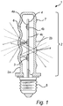
- a cross-sectional side view of the lighting device 1 comprising a housing 2 surrounding a plurality of light sources 3 arranged on a substrate 4 and an end of the housing 2 is attached to a electrical connector fitting 5 in this case a standard threaded fitting.
- the lighting device 1 is, in Fig. 1 , arranged for retrofit fittings, i.e. to fit in a luminaire initially designed for a conventional lighting device, such as a light bulb.
- a conventional lighting device such as a light bulb.
- other electrical connector fittings are conceivable such as a bayonet fitting, a clamp fitting, a plug fitting, or any fitting conceivable for luminaires.
- the plurality of light sources 3, here three light emitting diodes, are mounted on the substrate 4 such as a PCB on a first surface 4a, such that each of the light sources 3 face the same direction and have a common general output direction.
- the substrate 4 is substantially parallel to the fastening means axis, in this embodiment a rotational axis centered around the electrical connector fitting 5.
- the light sources 3 are facing a first portion 2a of the housing 2 having a first optical element 6 arranged opposite each light source 3.
- Each of the first optical elements 6 arranged in the first portion 2a of the housing 2 is a combination of a reflector and a transmitter configured to both reflect and transmit light from the light sources 3.
- the housing 2 may comprise a light transmissive material arranged to scatter and diffuse light exiting the housing 2.
- the housing 2 has a second portion 2b generally opposite the first portion 2a with respect to the substrate 4.
- a plurality of second optical elements 7 are arranged from the electrical connector fitting 5 to the top along the second portion 2b.
- the second optical elements 7 are preferably arranged in the same elevation as the through-holes 4c, i.e. in between the light sources 3.
- the reflective portion of the first optical element 5 may have protruding shapes such as a triangular shape, half-spherical shape, however, other shapes may also be conceivable that provides an angle to reflect the light at the side each light source 3.
- the plurality of first optical elements 6 may comprise a reflective coating.
- the reflective coating may be arranged such that a portion of the light is reflected while the rest is transmitted through the first optical element 6.
- the reflectivity may be graded such that one portion has a higher reflectivity than another to provide a desired light distribution.
- the light reflected by the protruding portion of the first optical element 6 is directed at the sides of each light source 3 and passes the substrate 4 through through-holes or transmissive areas 4c towards the second portion 2b of the housing 2 arranged substantially opposite the first portion 2a of the housing 2, in particularly towards the second optical elements 7.
- the second optical elements 7 are lenses arranged to increase the angular spread the exiting light of the reflected light.
- Fig. 1 schematic rays of light have been depicted to illustrate the light path through the lighting device 1 and describe the functionality of the first optical elements 6, the through-holes 4c and the second optical element 7.
- the light sources 3 mounted on the first side 4a of the substrate 4 emit light in the same direction toward the first optical elements 6, wherein the central output direction of the light sources 3 is generally perpendicular with respect the plane of the substrate 4.
- the central output direction of the light sources 3 is generally perpendicular to the axis of rotation for the fastening means, i.e. the electrical connector fitting 5.
- Light reaching the first optical elements 6 is either transmitted and refracted through the element or reflected.
- the first optical elements 6 in this embodiment comprises a lens, such as a concave lens, and a mirror, the light exiting the element 6 is refracted and provides light in additional output directions when exiting the lighting device 1.
- two schematic light rays have been drawn for each of the two light sources, one light ray representing an incoming light ray at the centre of reflective portion of the first optical elements 6, such as a mirror, and the other light ray representing the incoming light at the peripheral reflective portion of the first optical elements 6.
- Each of these light rays is transmitted through the through-holes 4c towards the second optical elements 7 to be refracted and increase the light output distribution for the reflected light.
- the dashed light continuing from the reflected light in the surrounding represents the rays if light were not refracted by the second optical elements 7.
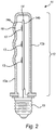
- Fig. 2 depicting a cross-sectional side view of a lighting device 11 as described in Fig. 1 , but in this case without any second optical elements to increase the angular spread from light exiting the second portion 12b of the housing 12 and the substrate 14 comprises a transmissive material 14c according to an embodiment of the invention.
- the first portion 12a of the housing 12 with the first optical elements 16 is arranged as described in Fig. 1 , however, the light sources 13 are mounted on a light transmissive substrate 14, such as a light transmissive PCB.
- the substrate 14 is generally arranged to transmit visible wavelengths of light. Light reflected from the first optical element 16 may thus be transmitted though the transmissive material towards the second portion 12b of the housing 12.
- the second portion 12b of the housing 12, arranged along the opposite side of the first portion 12a of the housing 12 having the first optical elements 16, may comprise scattering particles, such as high scattering non-absorbing particles, such as for example TiO 2 , Al 2 O 3 or SiO 2 . Scattering particles in the housing 13 may diffuse exiting light providing a softer and more evenly distributed light output distribution.
- the scattering particles may be integrated in a sheet, or be added in several layers allowing diffusivity.
- the housing 12 and in particular the first optical elements 16 and first portion 12a of the housing 12 may comprise scattering particles, such as for example TiO 2 , Al 2 O 3 or SiO 2 .
- the transmittance is determined by the amount of light being transmitted through a material compared to the amount of incoming light.
- the amount of scattering particles may determine the amount of light being transmitted and how much light is reflected back. Increasing amounts of scatterers may decrease the transmittance.
- the first optical element 16 may thus be integrated in the housing 12.
- the thickness of the scattering particles may determined the reflectance and transmittance.
- the diffusing portion may be integrated in a sheet, or be added in several layers allowing diffusivity. Variations in thickness or concentration of scattering particles may thus provide a varied reflectance magnitude over each of the first optical elements 6.
- a cut-out cross-sectional side view of a lighting device 21 is illustrated according to an embodiment of the present invention.
- the cross-sectional cut-out side view of the lighting device 21 depicts a portion of a compact lighting device having a electric connector fitting 25.
- the lighting device 21 provides a compact lighting device by providing a substrate 24 having a plurality of light sources 23 mounted on a first side 24a while the opposite side, a second side 24b of the substrate, is attached along the inner side of second portion 22b of the housing 22 from the base 25 of the lighting device to the peripheral part of the housing 22.
- parts of the first portion 22a of the housing 22 may be attached to the first substrate side 24a to further provide a compact lighting device 21.
- the substrate 24 is arranged with through-holes 24c such that reflected light may be transmitted from the first optical elements 26 towards the second portion 22b of the housing 22, in particular towards the second optical elements 27.
- the first optical element 26 is a combination of a reflector and a lens in embodiment illustrated in Fig. 3 .
- the central part of the first optical element 26 is arranged to reflect light while the peripheral part of the first optical elements 26 comprises a lens arranged to refract light to increase the angular spread, as is illustrated by the schematical light rays.
- the light exiting the first portion 22a of the housing 22 is refracted by the lens to increase the outputted light distribution.
- the schematical light rays describing the refracted light path is also illustrates in Fig. 3 .
- Light emitted from the light sources 23 reaches the first optical elements 26 and is reflected towards through-holes 24c in the substrate 24.
- the reflected light passes the substrate 24 through the through-holes 24c and continues on towards the second portion 22b of the housing 22 to be transmitted and refracted through the second optical element 27 such that an increased output light distribution for light exiting the second portion 22b of the housing 22 is provided.
- first optical elements 26 and the second optical elements 27 may be integrated in the first portion 22a of the housing 22 and the second portion 22b of the housing 22, respectively.
- the housing 2, 12, 22, first optical elements 6,16, 26 and/or second optical element 7, 27 may comprise polymer material, e.g. polymethyl methacrylate, PMMA, or PC-poly carbonate.
- the housing 2, 12, 22 may be made of glass.
- the light sources 3, 13, 23 may include integrated optical elements, such as a lens to further guide the light towards the first optical elements 6, 16, 26 according to predetermined directions.
- the first optical elements 6, 16, 26 may in some embodiments be integrated in the first portion 2a, 12a, 22a of the housing 2, 12, 22, such that the first portion 6, 16, 26 may comprise a lens shape and a reflective portion, in this embodiment the reflective portion is arranged in the centre while the lens is provided in the peripheral portions of the first optical elements 6, 16, 26, however, the reverse is also conceivable.
- first optical elements 6, 16, 26 may in some embodiments comprise a refractive lens having a refractive coating arranged to reflect a portion of the light. However, the first optical elements 6, 16, 26 may also be arranged between the first portion 2a, 12a, 22a of the housing 2, 12, 22 and the light sources 3, 13, 23, i.e. inside the housing 2, 12, 22.
- the lighting device 1, 11,21 may particularly be advantageous for retrofit fluorescent or solid state lighting or luminaires.
- first portion 2a, 12a, 22a of the housing 2, 12, 22 may generally be interpreted as a side along the housing 2, 12, 22 projecting from the fitting towards the end of the protruding housing 2, 12, 22, covering at most a portion of the housing arranged in front of the light sources 3, 13, 23 in the light output direction of the light sources 3, 13, 23.
- second portion 2b, 12b, 22b of the housing 2,12, 22 may generally be interpreted as a side along the housing 2, 12, 22 projecting from the base towards the end of the protruding housing opposite the first portion 2a, 12a, 22a of the housing.
- the second portion 2b, 12b, 22b of the housing covers at most a portion of the housing arranged in behind of the light sources 3, 13, 23, thus the opposite direction of the light output direction of the light sources 3, 13, 23.
- a driver unit or a driver circuit (not shown in the figures), for driving the light sources, may be arranged on the substrate 4, 14, 24.
- the driver unit and/or driver circuit may be adapted to modify at least one parameter of the light emitted from the light sources, such as the intensity of light.
- the driver circuit controls a current and voltage to the light sources.
- the driver circuit and/or driver unit is further electrically connected to the electrical connector fitting.
- the driver electronic may be arranged on the substrate.
- the reflective portion of the first optical element 6, 16, 26 may be arranged in the peripheral portions of the element 6, 16, 26 , while the transmitting portion is arranged in the centre of the first optical element 6, 16, 26.
- Parts of the system may be omitted, interchanged or arranged in various ways, the system may yet being able to perform the method of the present invention.
- the lighting device does not need to have a retrofit fitting as illustrated in Fig. 1-3 , the lighting device may be integrated in any type of luminaire, such as pendant luminaires, outdoor city beautification luminaires, corridor lighting and other flat luminaires that benefit from an omnidirectional light distribution.
Claims (14)
- Beleuchtungsvorrichtung (1, 11, 21), die Folgendes umfasst:ein Substrat (4, 14, 24) mit einer ersten Seite (4a, 14a, 24a) und einer zweiten Seite (4b, 14b, 24b);eine Vielzahl von Lichtquellen (3, 13, 23), die auf der ersten Seite des Substrats angeordnet sind, wobei die Lichtquellen eine gemeinsame allgemeine Ausgangsrichtung aufweisen,ein Gehäuse (2, 12, 22) aus einem lichtdurchlässigen Material, das das Substrat umgibt und angeordnet ist, Licht zu übertragen, einen ersten Abschnitt (2a, 12a, 22a) des Gehäuses aufweisend und einen zweiten Abschnitt (2b, 12b, 22b) des Gehäuses, der mit Bezug auf das Substrat im Wesentlichen gegenüber dem ersten Abschnitt angeordnet ist;eine Vielzahl von ersten optischen Elementen (6, 16, 26), die im Wesentlichen entgegen der Ausgangsrichtung der Vielzahl von Lichtquellen entlang dem ersten Abschnitt des Gehäuses gegenüber der ersten Seite des Substrats angeordnet sind,wobei das Substrat angepasst ist, eine Übertragung von Licht zu erlauben,wobei die Vielzahl erster optischer Elemente angeordnet ist, einen Teil des Lichts, das von den Lichtquellen emittiert wird, zu übertragen und einen Teil des Lichts, das von den Lichtquellen emittiert wird, durch das Substrat zum zweiten Abschnitt (2b, 12b, 22b) des Gehäuses hin zu reflektieren, undwobei jedes der Vielzahl erster optischer Elemente angeordnet ist, das Licht von den Lichtquellen zu brechen und zu reflektieren, gekennzeichnet durch,jedes der Vielzahl erster optischer Elemente umfasst einen Spiegel und eine Linse auf jeder Seite des Spiegels, wobei die Linsen angeordnet sind, durch Brechung von Licht, das durch die ersten optischen Elemente übertragen wird, eine erhöhte Winkelstreuung bereitzustellen.
- Beleuchtungsvorrichtung nach Anspruch 1, wobei der Abschnitt des Lichts, der von den ersten optischen Elementen zum zweiten Abschnitt des Gehäuses hin reflektiert wird, zwischen 30 % und 70 % des gesamten von der Vielzahl von Lichtquellen emittierten Lichts beträgt.
- Beleuchtungsvorrichtung nach Anspruch 1 oder 2, wobei das Substrat mindestens ein teilweise lichtdurchlässiges Material umfasst, das angeordnet ist, Licht, das von den ersten optischen Elementen zum zweiten Abschnitt des Gehäuses hin reflektiert wird, zu übertragen.
- Beleuchtungsvorrichtung nach Anspruch 1, wobei das Substrat mindestens ein Durchgangsloch (4c, 24c) zum mindestens teilweisen Übertragen von Licht, das von den ersten optischen Elementen zum zweiten Abschnitt des Gehäuses hin reflektiert wird, umfasst.
- Beleuchtungsvorrichtung nach einem der vorhergehenden Ansprüche, wobei die zweite Seite des Substrats entlang dem zweiten Abschnitt des Gehäuses befestigt ist.
- Beleuchtungsvorrichtung nach einem der vorhergehenden Ansprüche, wobei eine Vielzahl zweiter optischer Elemente (7, 27) entlang dem zweiten Abschnitt des Gehäuses angeordnet ist und die Vielzahl zweiter optischer Elemente angeordnet ist, das reflektierte Licht zu brechen, um eine erhöhte Winkelstreuung bereitzustellen.
- Beleuchtungsvorrichtung nach einem der vorhergehenden Ansprüche, wobei die Vielzahl erster optischer Elemente angeordnet ist, einen Teil des Lichts, das von der Vielzahl von Lichtquellen emittiert wird, in eine jeder Lichtquelle benachbarte Richtung zum zweiten Abschnitt des Gehäuses hin zu reflektieren.
- Beleuchtungsvorrichtung nach einem der vorhergehenden Ansprüche, wobei die Vielzahl erster optischer Elemente eine Beschichtung umfassen, die angeordnet ist, Licht teilweise zu reflektieren und teilweise zu übertragen.
- Beleuchtungsvorrichtung nach einem der vorhergehenden Ansprüche, wobei das lichtdurchlässige Material Partikel zum Verteilen und/oder Umwandeln einer Wellenlänge von Licht, das von den Lichtquellen emittiert wird, umfasst.
- Beleuchtungsvorrichtung nach einem der vorhergehenden Ansprüche, wobei die Lichtquellen elektrisch mit einer elektrischen Schaltung verbunden sind, die angeordnet ist, die Spannung oder die von den Lichtquellen bereitgestellte Leistung zu steuern.
- Beleuchtungsvorrichtung nach einem der vorhergehenden Ansprüche, wobei die Beleuchtungsvorrichtung einen elektrischen Verbindungsanschluss (5, 15, 25) umfasst, der dazu ausgelegt ist, der Vielzahl von Lichtquellen Spannung von einer externen Leistungsquelle bereitzustellen, wobei der elektrische Verbindungsanschluss an einem Ende des Gehäuses befestigt ist.
- Beleuchtungsvorrichtung nach Anspruch 11, wobei der elektrische Verbindungsanschluss ein nachrüstbarer Anschluss ist.
- Beleuchtungsvorrichtung nach einem der vorhergehenden Ansprüche, wobei die Lichtquellen lichtemittierende Dioden sind.
- Beleuchtungsvorrichtung nach Anspruch 11, wobei das Substrat parallel zu einer Drehachse des elektrischen Verbindungsanschlusses verläuft und/oder wobei eine zentrale Ausgangsrichtung der Lichtquellen senkrecht zur Drehachse für den elektrischen Verbindungsanschluss steht.
Priority Applications (1)
| Application Number | Priority Date | Filing Date | Title |
|---|---|---|---|
| PL15701156T PL3105495T3 (pl) | 2014-01-30 | 2015-01-20 | Urządzenie oświetleniowe |
Applications Claiming Priority (2)
| Application Number | Priority Date | Filing Date | Title |
|---|---|---|---|
| EP14153167 | 2014-01-30 | ||
| PCT/EP2015/050914 WO2015113852A1 (en) | 2014-01-30 | 2015-01-20 | Lighting device |
Publications (2)
| Publication Number | Publication Date |
|---|---|
| EP3105495A1 EP3105495A1 (de) | 2016-12-21 |
| EP3105495B1 true EP3105495B1 (de) | 2017-11-01 |
Family
ID=50028856
Family Applications (1)
| Application Number | Title | Priority Date | Filing Date |
|---|---|---|---|
| EP15701156.0A Active EP3105495B1 (de) | 2014-01-30 | 2015-01-20 | Beleuchtungsvorrichtung |
Country Status (7)
| Country | Link |
|---|---|
| US (1) | US10655790B2 (de) |
| EP (1) | EP3105495B1 (de) |
| JP (1) | JP6549595B2 (de) |
| CN (1) | CN105960560B (de) |
| PL (1) | PL3105495T3 (de) |
| RU (1) | RU2707185C2 (de) |
| WO (1) | WO2015113852A1 (de) |
Families Citing this family (7)
| Publication number | Priority date | Publication date | Assignee | Title |
|---|---|---|---|---|
| KR102432261B1 (ko) * | 2016-09-29 | 2022-08-16 | 루미리즈 홀딩 비.브이. | 확산기를 갖는 조명 어셈블리 |
| DE102017110378B4 (de) * | 2017-05-12 | 2023-03-02 | Ledvance Gmbh | LED-Lampe mit LED-Leuchtmittel |
| DE102017115885A1 (de) | 2017-07-14 | 2019-01-17 | Ledvance Gmbh | LED-Leuchtmittel und LED-Lampe |
| JP2019161062A (ja) * | 2018-03-14 | 2019-09-19 | 豊田合成株式会社 | 発光装置 |
| IT201900005434A1 (it) * | 2019-04-09 | 2020-10-09 | Artemide Spa | Dispositivo di illuminazione |
| WO2020227497A1 (en) * | 2019-05-09 | 2020-11-12 | Jeffway Jr Robert W | Two-sided illuminating printed circuit board assembly and illuminating device using the same |
| DE202022102261U1 (de) * | 2022-04-27 | 2023-08-07 | Thorn Lighting Limited | Flächenleuchte mit rückseitiger (Sekundär-)Beleuchtung |
Family Cites Families (29)
| Publication number | Priority date | Publication date | Assignee | Title |
|---|---|---|---|---|
| US3610912A (en) * | 1968-08-14 | 1971-10-05 | Varian Associates | Low profile optical system |
| US3586851A (en) * | 1969-02-24 | 1971-06-22 | Robert R Rudolph | Cool light |
| US5947588A (en) * | 1997-10-06 | 1999-09-07 | Grand General Accessories Manufacturing Inc. | Light fixture with an LED light bulb having a conventional connection post |
| DE20018435U1 (de) * | 2000-10-27 | 2001-02-22 | Shining Blick Entpr Co | Glühbirne mit darin enthaltenen biegbaren Lampenbirnchen |
| JP4076329B2 (ja) * | 2001-08-13 | 2008-04-16 | エイテックス株式会社 | Led電球 |
| JP2005038822A (ja) * | 2003-06-26 | 2005-02-10 | Sharp Corp | フラットパネルディスプレイ用照明装置、および、発光ランプ |
| JP4042687B2 (ja) * | 2003-12-15 | 2008-02-06 | ソニー株式会社 | 照明装置及びバックライト装置 |
| US6948829B2 (en) * | 2004-01-28 | 2005-09-27 | Dialight Corporation | Light emitting diode (LED) light bulbs |
| JP2007165811A (ja) * | 2005-12-16 | 2007-06-28 | Nichia Chem Ind Ltd | 発光装置 |
| EP2212928B1 (de) * | 2007-11-20 | 2016-06-29 | Koninklijke Philips N.V. | Seitlich emittierende vorrichtung mit wellenlängenumwandlung |
| US8360599B2 (en) * | 2008-05-23 | 2013-01-29 | Ilumisys, Inc. | Electric shock resistant L.E.D. based light |
| CN101614329A (zh) * | 2008-06-27 | 2009-12-30 | 富准精密工业(深圳)有限公司 | 发光二极管灯具及其光引擎 |
| KR101155690B1 (ko) | 2009-12-18 | 2012-06-12 | (주)아이디시스테크 | 소형 필라멘트 전구 대체용 소형 엘이디 램프 |
| CA2794512A1 (en) * | 2010-03-26 | 2011-09-29 | David L. Simon | Led light tube with dual sided light distribution |
| US8833981B2 (en) * | 2010-04-23 | 2014-09-16 | Illumination Machines, Llc | Multiple-tier omnidirectional solid-state emission source |
| JP5545547B2 (ja) * | 2010-10-07 | 2014-07-09 | 東芝ライテック株式会社 | 光源体および照明器具 |
| JP5276226B2 (ja) * | 2010-10-22 | 2013-08-28 | パナソニック株式会社 | 実装用基板、発光装置及びランプ |
| WO2012060106A1 (ja) * | 2010-11-04 | 2012-05-10 | パナソニック株式会社 | 電球形ランプ及び照明装置 |
| JP2012104295A (ja) | 2010-11-08 | 2012-05-31 | Stanley Electric Co Ltd | Led照明装置 |
| JP5984845B2 (ja) * | 2011-01-11 | 2016-09-06 | コーニンクレッカ フィリップス エヌ ヴェKoninklijke Philips N.V. | 照明装置 |
| US8714762B2 (en) * | 2011-05-03 | 2014-05-06 | Zhou Cai | LED light source and manufacturing method thereof |
| JP2012248687A (ja) * | 2011-05-27 | 2012-12-13 | Toshiba Lighting & Technology Corp | 発光モジュール及び照明装置 |
| US8324790B1 (en) * | 2011-06-07 | 2012-12-04 | Wen-Sung Hu | High illumination LED bulb with full emission angle |
| WO2013043743A1 (en) | 2011-09-19 | 2013-03-28 | Ruud Lighting, Inc. | Led retrofit lighting fixture |
| KR101344513B1 (ko) * | 2012-02-07 | 2013-12-23 | 엘이디라이텍(주) | 엘이디 램프 조립체 |
| US8757839B2 (en) * | 2012-04-13 | 2014-06-24 | Cree, Inc. | Gas cooled LED lamp |
| US9395051B2 (en) * | 2012-04-13 | 2016-07-19 | Cree, Inc. | Gas cooled LED lamp |
| US20140168978A1 (en) * | 2012-12-17 | 2014-06-19 | Wen-Sung Hu | Full-Beam-Angle LED Bulb Structure |
| CN203348993U (zh) * | 2013-06-26 | 2013-12-18 | 广东恒润光电有限公司 | 蜡烛灯 |
-
2015
- 2015-01-20 PL PL15701156T patent/PL3105495T3/pl unknown
- 2015-01-20 US US15/115,060 patent/US10655790B2/en active Active
- 2015-01-20 JP JP2016549089A patent/JP6549595B2/ja active Active
- 2015-01-20 EP EP15701156.0A patent/EP3105495B1/de active Active
- 2015-01-20 RU RU2016135041A patent/RU2707185C2/ru active
- 2015-01-20 WO PCT/EP2015/050914 patent/WO2015113852A1/en active Application Filing
- 2015-01-20 CN CN201580006528.2A patent/CN105960560B/zh active Active
Non-Patent Citations (1)
| Title |
|---|
| None * |
Also Published As
| Publication number | Publication date |
|---|---|
| RU2016135041A3 (de) | 2018-09-13 |
| CN105960560B (zh) | 2020-01-07 |
| RU2016135041A (ru) | 2018-03-05 |
| PL3105495T3 (pl) | 2018-04-30 |
| US20160348852A1 (en) | 2016-12-01 |
| WO2015113852A1 (en) | 2015-08-06 |
| JP6549595B2 (ja) | 2019-07-24 |
| RU2707185C2 (ru) | 2019-11-25 |
| EP3105495A1 (de) | 2016-12-21 |
| US10655790B2 (en) | 2020-05-19 |
| CN105960560A (zh) | 2016-09-21 |
| JP2017504944A (ja) | 2017-02-09 |
Similar Documents
| Publication | Publication Date | Title |
|---|---|---|
| US11693174B2 (en) | Illumination device for direct-indirect illumination | |
| EP3105495B1 (de) | Beleuchtungsvorrichtung | |
| RU2519278C2 (ru) | Световой источник со светодиодами, световодом и отражателем | |
| JP5734204B2 (ja) | 光学要素及び当該光学要素を有する光源 | |
| JP5711147B2 (ja) | Led、光ガイド及びリフレクタを備える光源 | |
| US10480721B2 (en) | Light flux controlling member, light emitting device and illuminating device | |
| US20150247621A1 (en) | Light flux controlling member, light emitting device and illumination apparatus | |
| JP2014103062A (ja) | 照明装置 | |
| WO2015129671A1 (ja) | 照明器具、光源カバー、光制御部材、および光源ユニット | |
| JP2015149133A (ja) | 照明装置 | |
| WO2016181789A1 (ja) | 光束制御部材、発光装置および照明装置 |
Legal Events
| Date | Code | Title | Description |
|---|---|---|---|
| PUAI | Public reference made under article 153(3) epc to a published international application that has entered the european phase |
Free format text: ORIGINAL CODE: 0009012 |
|
| 17P | Request for examination filed |
Effective date: 20160830 |
|
| AK | Designated contracting states |
Kind code of ref document: A1 Designated state(s): AL AT BE BG CH CY CZ DE DK EE ES FI FR GB GR HR HU IE IS IT LI LT LU LV MC MK MT NL NO PL PT RO RS SE SI SK SM TR |
|
| AX | Request for extension of the european patent |
Extension state: BA ME |
|
| REG | Reference to a national code |
Ref country code: DE Ref legal event code: R079 Ref document number: 602015005730 Country of ref document: DE Free format text: PREVIOUS MAIN CLASS: F21K0099000000 Ipc: F21K0009232000 |
|
| DAX | Request for extension of the european patent (deleted) | ||
| GRAP | Despatch of communication of intention to grant a patent |
Free format text: ORIGINAL CODE: EPIDOSNIGR1 |
|
| RIC1 | Information provided on ipc code assigned before grant |
Ipc: F21V 23/00 20150101ALI20170427BHEP Ipc: F21V 7/00 20060101ALN20170427BHEP Ipc: F21K 9/232 20160101AFI20170427BHEP Ipc: F21V 5/00 20150101ALN20170427BHEP Ipc: F21K 9/238 20160101ALI20170427BHEP Ipc: F21Y 115/10 20160101ALN20170427BHEP Ipc: F21V 13/04 20060101ALI20170427BHEP Ipc: F21V 3/02 20060101ALI20170427BHEP |
|
| INTG | Intention to grant announced |
Effective date: 20170530 |
|
| RIN1 | Information on inventor provided before grant (corrected) |
Inventor name: KAANDORP, WOUTER PETRUS Inventor name: LIEDENBAUM, COEN THEODORUS HUBERTUS FRANSISCUS |
|
| GRAS | Grant fee paid |
Free format text: ORIGINAL CODE: EPIDOSNIGR3 |
|
| GRAA | (expected) grant |
Free format text: ORIGINAL CODE: 0009210 |
|
| AK | Designated contracting states |
Kind code of ref document: B1 Designated state(s): AL AT BE BG CH CY CZ DE DK EE ES FI FR GB GR HR HU IE IS IT LI LT LU LV MC MK MT NL NO PL PT RO RS SE SI SK SM TR |
|
| REG | Reference to a national code |
Ref country code: GB Ref legal event code: FG4D |
|
| REG | Reference to a national code |
Ref country code: CH Ref legal event code: EP Ref country code: AT Ref legal event code: REF Ref document number: 942393 Country of ref document: AT Kind code of ref document: T Effective date: 20171115 |
|
| REG | Reference to a national code |
Ref country code: IE Ref legal event code: FG4D |
|
| REG | Reference to a national code |
Ref country code: DE Ref legal event code: R096 Ref document number: 602015005730 Country of ref document: DE |
|
| REG | Reference to a national code |
Ref country code: SE Ref legal event code: TRGR |
|
| REG | Reference to a national code |
Ref country code: NL Ref legal event code: MP Effective date: 20171101 |
|
| REG | Reference to a national code |
Ref country code: LT Ref legal event code: MG4D |
|
| REG | Reference to a national code |
Ref country code: AT Ref legal event code: MK05 Ref document number: 942393 Country of ref document: AT Kind code of ref document: T Effective date: 20171101 |
|
| PG25 | Lapsed in a contracting state [announced via postgrant information from national office to epo] |
Ref country code: ES Free format text: LAPSE BECAUSE OF FAILURE TO SUBMIT A TRANSLATION OF THE DESCRIPTION OR TO PAY THE FEE WITHIN THE PRESCRIBED TIME-LIMIT Effective date: 20171101 Ref country code: NO Free format text: LAPSE BECAUSE OF FAILURE TO SUBMIT A TRANSLATION OF THE DESCRIPTION OR TO PAY THE FEE WITHIN THE PRESCRIBED TIME-LIMIT Effective date: 20180201 Ref country code: NL Free format text: LAPSE BECAUSE OF FAILURE TO SUBMIT A TRANSLATION OF THE DESCRIPTION OR TO PAY THE FEE WITHIN THE PRESCRIBED TIME-LIMIT Effective date: 20171101 Ref country code: FI Free format text: LAPSE BECAUSE OF FAILURE TO SUBMIT A TRANSLATION OF THE DESCRIPTION OR TO PAY THE FEE WITHIN THE PRESCRIBED TIME-LIMIT Effective date: 20171101 Ref country code: LT Free format text: LAPSE BECAUSE OF FAILURE TO SUBMIT A TRANSLATION OF THE DESCRIPTION OR TO PAY THE FEE WITHIN THE PRESCRIBED TIME-LIMIT Effective date: 20171101 |
|
| PG25 | Lapsed in a contracting state [announced via postgrant information from national office to epo] |
Ref country code: GR Free format text: LAPSE BECAUSE OF FAILURE TO SUBMIT A TRANSLATION OF THE DESCRIPTION OR TO PAY THE FEE WITHIN THE PRESCRIBED TIME-LIMIT Effective date: 20180202 Ref country code: AT Free format text: LAPSE BECAUSE OF FAILURE TO SUBMIT A TRANSLATION OF THE DESCRIPTION OR TO PAY THE FEE WITHIN THE PRESCRIBED TIME-LIMIT Effective date: 20171101 Ref country code: HR Free format text: LAPSE BECAUSE OF FAILURE TO SUBMIT A TRANSLATION OF THE DESCRIPTION OR TO PAY THE FEE WITHIN THE PRESCRIBED TIME-LIMIT Effective date: 20171101 Ref country code: BG Free format text: LAPSE BECAUSE OF FAILURE TO SUBMIT A TRANSLATION OF THE DESCRIPTION OR TO PAY THE FEE WITHIN THE PRESCRIBED TIME-LIMIT Effective date: 20180201 Ref country code: LV Free format text: LAPSE BECAUSE OF FAILURE TO SUBMIT A TRANSLATION OF THE DESCRIPTION OR TO PAY THE FEE WITHIN THE PRESCRIBED TIME-LIMIT Effective date: 20171101 Ref country code: RS Free format text: LAPSE BECAUSE OF FAILURE TO SUBMIT A TRANSLATION OF THE DESCRIPTION OR TO PAY THE FEE WITHIN THE PRESCRIBED TIME-LIMIT Effective date: 20171101 Ref country code: IS Free format text: LAPSE BECAUSE OF FAILURE TO SUBMIT A TRANSLATION OF THE DESCRIPTION OR TO PAY THE FEE WITHIN THE PRESCRIBED TIME-LIMIT Effective date: 20180301 |
|
| PG25 | Lapsed in a contracting state [announced via postgrant information from national office to epo] |
Ref country code: DK Free format text: LAPSE BECAUSE OF FAILURE TO SUBMIT A TRANSLATION OF THE DESCRIPTION OR TO PAY THE FEE WITHIN THE PRESCRIBED TIME-LIMIT Effective date: 20171101 Ref country code: CY Free format text: LAPSE BECAUSE OF FAILURE TO SUBMIT A TRANSLATION OF THE DESCRIPTION OR TO PAY THE FEE WITHIN THE PRESCRIBED TIME-LIMIT Effective date: 20171101 Ref country code: EE Free format text: LAPSE BECAUSE OF FAILURE TO SUBMIT A TRANSLATION OF THE DESCRIPTION OR TO PAY THE FEE WITHIN THE PRESCRIBED TIME-LIMIT Effective date: 20171101 Ref country code: SK Free format text: LAPSE BECAUSE OF FAILURE TO SUBMIT A TRANSLATION OF THE DESCRIPTION OR TO PAY THE FEE WITHIN THE PRESCRIBED TIME-LIMIT Effective date: 20171101 Ref country code: CZ Free format text: LAPSE BECAUSE OF FAILURE TO SUBMIT A TRANSLATION OF THE DESCRIPTION OR TO PAY THE FEE WITHIN THE PRESCRIBED TIME-LIMIT Effective date: 20171101 |
|
| REG | Reference to a national code |
Ref country code: DE Ref legal event code: R097 Ref document number: 602015005730 Country of ref document: DE |
|
| PG25 | Lapsed in a contracting state [announced via postgrant information from national office to epo] |
Ref country code: IT Free format text: LAPSE BECAUSE OF FAILURE TO SUBMIT A TRANSLATION OF THE DESCRIPTION OR TO PAY THE FEE WITHIN THE PRESCRIBED TIME-LIMIT Effective date: 20171101 Ref country code: SM Free format text: LAPSE BECAUSE OF FAILURE TO SUBMIT A TRANSLATION OF THE DESCRIPTION OR TO PAY THE FEE WITHIN THE PRESCRIBED TIME-LIMIT Effective date: 20171101 |
|
| REG | Reference to a national code |
Ref country code: CH Ref legal event code: PL |
|
| PLBE | No opposition filed within time limit |
Free format text: ORIGINAL CODE: 0009261 |
|
| STAA | Information on the status of an ep patent application or granted ep patent |
Free format text: STATUS: NO OPPOSITION FILED WITHIN TIME LIMIT |
|
| 26N | No opposition filed |
Effective date: 20180802 |
|
| PG25 | Lapsed in a contracting state [announced via postgrant information from national office to epo] |
Ref country code: FR Free format text: LAPSE BECAUSE OF NON-PAYMENT OF DUE FEES Effective date: 20180131 Ref country code: LU Free format text: LAPSE BECAUSE OF NON-PAYMENT OF DUE FEES Effective date: 20180120 |
|
| REG | Reference to a national code |
Ref country code: IE Ref legal event code: MM4A |
|
| REG | Reference to a national code |
Ref country code: FR Ref legal event code: ST Effective date: 20180928 |
|
| REG | Reference to a national code |
Ref country code: BE Ref legal event code: MM Effective date: 20180131 |
|
| PG25 | Lapsed in a contracting state [announced via postgrant information from national office to epo] |
Ref country code: SI Free format text: LAPSE BECAUSE OF FAILURE TO SUBMIT A TRANSLATION OF THE DESCRIPTION OR TO PAY THE FEE WITHIN THE PRESCRIBED TIME-LIMIT Effective date: 20171101 Ref country code: CH Free format text: LAPSE BECAUSE OF NON-PAYMENT OF DUE FEES Effective date: 20180131 Ref country code: BE Free format text: LAPSE BECAUSE OF NON-PAYMENT OF DUE FEES Effective date: 20180131 Ref country code: LI Free format text: LAPSE BECAUSE OF NON-PAYMENT OF DUE FEES Effective date: 20180131 |
|
| PG25 | Lapsed in a contracting state [announced via postgrant information from national office to epo] |
Ref country code: IE Free format text: LAPSE BECAUSE OF NON-PAYMENT OF DUE FEES Effective date: 20180120 |
|
| PG25 | Lapsed in a contracting state [announced via postgrant information from national office to epo] |
Ref country code: MC Free format text: LAPSE BECAUSE OF FAILURE TO SUBMIT A TRANSLATION OF THE DESCRIPTION OR TO PAY THE FEE WITHIN THE PRESCRIBED TIME-LIMIT Effective date: 20171101 |
|
| PG25 | Lapsed in a contracting state [announced via postgrant information from national office to epo] |
Ref country code: MT Free format text: LAPSE BECAUSE OF NON-PAYMENT OF DUE FEES Effective date: 20180120 |
|
| PG25 | Lapsed in a contracting state [announced via postgrant information from national office to epo] |
Ref country code: TR Free format text: LAPSE BECAUSE OF FAILURE TO SUBMIT A TRANSLATION OF THE DESCRIPTION OR TO PAY THE FEE WITHIN THE PRESCRIBED TIME-LIMIT Effective date: 20171101 |
|
| PG25 | Lapsed in a contracting state [announced via postgrant information from national office to epo] |
Ref country code: PT Free format text: LAPSE BECAUSE OF FAILURE TO SUBMIT A TRANSLATION OF THE DESCRIPTION OR TO PAY THE FEE WITHIN THE PRESCRIBED TIME-LIMIT Effective date: 20171101 |
|
| PG25 | Lapsed in a contracting state [announced via postgrant information from national office to epo] |
Ref country code: MK Free format text: LAPSE BECAUSE OF NON-PAYMENT OF DUE FEES Effective date: 20171101 Ref country code: HU Free format text: LAPSE BECAUSE OF FAILURE TO SUBMIT A TRANSLATION OF THE DESCRIPTION OR TO PAY THE FEE WITHIN THE PRESCRIBED TIME-LIMIT; INVALID AB INITIO Effective date: 20150120 Ref country code: RO Free format text: LAPSE BECAUSE OF FAILURE TO SUBMIT A TRANSLATION OF THE DESCRIPTION OR TO PAY THE FEE WITHIN THE PRESCRIBED TIME-LIMIT Effective date: 20171101 |
|
| PG25 | Lapsed in a contracting state [announced via postgrant information from national office to epo] |
Ref country code: AL Free format text: LAPSE BECAUSE OF FAILURE TO SUBMIT A TRANSLATION OF THE DESCRIPTION OR TO PAY THE FEE WITHIN THE PRESCRIBED TIME-LIMIT Effective date: 20171101 |
|
| REG | Reference to a national code |
Ref country code: DE Ref legal event code: R081 Ref document number: 602015005730 Country of ref document: DE Owner name: SIGNIFY HOLDING B.V., NL Free format text: FORMER OWNER: PHILIPS LIGHTING HOLDING B.V., EINDHOVEN, NL |
|
| PGFP | Annual fee paid to national office [announced via postgrant information from national office to epo] |
Ref country code: SE Payment date: 20230124 Year of fee payment: 9 Ref country code: PL Payment date: 20230111 Year of fee payment: 9 Ref country code: GB Payment date: 20230124 Year of fee payment: 9 Ref country code: DE Payment date: 20230328 Year of fee payment: 9 |
|
| P01 | Opt-out of the competence of the unified patent court (upc) registered |
Effective date: 20230421 |