EP3105437B1 - Refroidissement d'aubes directrices creuses de moteur à turbine - Google Patents
Refroidissement d'aubes directrices creuses de moteur à turbine Download PDFInfo
- Publication number
- EP3105437B1 EP3105437B1 EP15748506.1A EP15748506A EP3105437B1 EP 3105437 B1 EP3105437 B1 EP 3105437B1 EP 15748506 A EP15748506 A EP 15748506A EP 3105437 B1 EP3105437 B1 EP 3105437B1
- Authority
- EP
- European Patent Office
- Prior art keywords
- insert
- scoops
- flat plate
- edge cavity
- cooling
- Prior art date
- Legal status (The legal status is an assumption and is not a legal conclusion. Google has not performed a legal analysis and makes no representation as to the accuracy of the status listed.)
- Active
Links
Images


Classifications
-
- F—MECHANICAL ENGINEERING; LIGHTING; HEATING; WEAPONS; BLASTING
- F01—MACHINES OR ENGINES IN GENERAL; ENGINE PLANTS IN GENERAL; STEAM ENGINES
- F01D—NON-POSITIVE DISPLACEMENT MACHINES OR ENGINES, e.g. STEAM TURBINES
- F01D9/00—Stators
- F01D9/06—Fluid supply conduits to nozzles or the like
- F01D9/065—Fluid supply or removal conduits traversing the working fluid flow, e.g. for lubrication-, cooling-, or sealing fluids
-
- F—MECHANICAL ENGINEERING; LIGHTING; HEATING; WEAPONS; BLASTING
- F01—MACHINES OR ENGINES IN GENERAL; ENGINE PLANTS IN GENERAL; STEAM ENGINES
- F01D—NON-POSITIVE DISPLACEMENT MACHINES OR ENGINES, e.g. STEAM TURBINES
- F01D5/00—Blades; Blade-carrying members; Heating, heat-insulating, cooling or antivibration means on the blades or the members
- F01D5/12—Blades
- F01D5/14—Form or construction
- F01D5/18—Hollow blades, i.e. blades with cooling or heating channels or cavities; Heating, heat-insulating or cooling means on blades
- F01D5/187—Convection cooling
- F01D5/188—Convection cooling with an insert in the blade cavity to guide the cooling fluid, e.g. forming a separation wall
- F01D5/189—Convection cooling with an insert in the blade cavity to guide the cooling fluid, e.g. forming a separation wall the insert having a tubular cross-section, e.g. airfoil shape
-
- F—MECHANICAL ENGINEERING; LIGHTING; HEATING; WEAPONS; BLASTING
- F05—INDEXING SCHEMES RELATING TO ENGINES OR PUMPS IN VARIOUS SUBCLASSES OF CLASSES F01-F04
- F05D—INDEXING SCHEME FOR ASPECTS RELATING TO NON-POSITIVE-DISPLACEMENT MACHINES OR ENGINES, GAS-TURBINES OR JET-PROPULSION PLANTS
- F05D2240/00—Components
- F05D2240/10—Stators
- F05D2240/12—Fluid guiding means, e.g. vanes
- F05D2240/127—Vortex generators, turbulators, or the like, for mixing
-
- F—MECHANICAL ENGINEERING; LIGHTING; HEATING; WEAPONS; BLASTING
- F05—INDEXING SCHEMES RELATING TO ENGINES OR PUMPS IN VARIOUS SUBCLASSES OF CLASSES F01-F04
- F05D—INDEXING SCHEME FOR ASPECTS RELATING TO NON-POSITIVE-DISPLACEMENT MACHINES OR ENGINES, GAS-TURBINES OR JET-PROPULSION PLANTS
- F05D2260/00—Function
- F05D2260/20—Heat transfer, e.g. cooling
- F05D2260/201—Heat transfer, e.g. cooling by impingement of a fluid
-
- F—MECHANICAL ENGINEERING; LIGHTING; HEATING; WEAPONS; BLASTING
- F05—INDEXING SCHEMES RELATING TO ENGINES OR PUMPS IN VARIOUS SUBCLASSES OF CLASSES F01-F04
- F05D—INDEXING SCHEME FOR ASPECTS RELATING TO NON-POSITIVE-DISPLACEMENT MACHINES OR ENGINES, GAS-TURBINES OR JET-PROPULSION PLANTS
- F05D2260/00—Function
- F05D2260/20—Heat transfer, e.g. cooling
- F05D2260/221—Improvement of heat transfer
- F05D2260/2212—Improvement of heat transfer by creating turbulence
-
- Y—GENERAL TAGGING OF NEW TECHNOLOGICAL DEVELOPMENTS; GENERAL TAGGING OF CROSS-SECTIONAL TECHNOLOGIES SPANNING OVER SEVERAL SECTIONS OF THE IPC; TECHNICAL SUBJECTS COVERED BY FORMER USPC CROSS-REFERENCE ART COLLECTIONS [XRACs] AND DIGESTS
- Y02—TECHNOLOGIES OR APPLICATIONS FOR MITIGATION OR ADAPTATION AGAINST CLIMATE CHANGE
- Y02T—CLIMATE CHANGE MITIGATION TECHNOLOGIES RELATED TO TRANSPORTATION
- Y02T50/00—Aeronautics or air transport
- Y02T50/60—Efficient propulsion technologies, e.g. for aircraft
Definitions
- This disclosure generally relates to an airfoil including an internal cooling chamber and baffle. More particularly, this disclosure relates to a turbine engine vane including chambers for preferentially directing cooling air within the cooling chamber.
- An airfoil utilized within a gas turbine engine includes a cooling chamber within which cooling air flows to remove heat from an inner surface of a wall exposed to extreme temperatures.
- a baffle within the cooling chamber includes a plurality of openings for directing air to impinge directly against the inner surface of the hot wall. The impingement of the cooling air against the hot wall improves cooling efficiencies.
- Cooling efficiencies are further improved with heat transfer features formed on the surfaces of the cooling chamber.
- Some materials that include favorable temperature performance properties are not easily manufactured to include heat transfer features.
- some materials may experience undesirable heat distributions with heat transfer features formed within a surface or structure exposed to high temperature gas flows.
- EP 1 284 338 discloses a turbine engine vane as set forth in the preamble of claim 1.
- US 2013/280091 A1 discloses gas turbine engine airfoil impingement cooling.
- US 5,419,039 discloses a method of making an air cooled vane with a film cooling pocket construction.
- the present invention provides a turbine engine vane as recited in claim 1.
- of flat plate insert scoops are configured to generate turbulent cooling airflow on the first side of the flat plate insert.
- the baffle insert divides the leading edge cavity into separate channels comprising an interior channel for receiving cooling airflow and an exterior channel defined between the inner surface and the insert that receives cooling airflow through the plurality of scoops.
- the plurality of baffle insert scoops are arranged in rows across the insert and each of the rows is staggered relative to adjacent rows.
- the airfoil includes a plurality of film cooling holes for communicating cooling airflow from the leading and trailing edge cavities to an outer surface of the airfoil.
- the invention also provides turbine engine as recited in claim 6.
- the invention also provides a method of cooling a turbine engine vane as recited in claim 9.
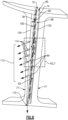
- FIG. 1 schematically illustrates a gas turbine engine 20.
- the gas turbine engine 20 is disclosed herein as a two-spool turbofan that generally incorporates a fan section 22, a compressor section 24, a combustor section 26 and a turbine section 28.
- Alternative engines might include an augmentor section (not shown) among other systems or features.
- the fan section 22 drives air along a bypass flow path B in a bypass duct defined within a nacelle 15, while the compressor section 24 drives air along a core flow path C for compression and communication into the combustor section 26 then expansion through the turbine section 28.
- the exemplary engine 20 generally includes a low speed spool 30 and a high speed spool 32 mounted for rotation about an engine central longitudinal axis A relative to an engine static structure 36 via several bearing systems 38. It should be understood that various bearing systems 38 at various locations may alternatively or additionally be provided and the location of bearing systems 38 may be varied as appropriate to the application.
- the low speed spool 30 generally includes an inner shaft 40 that interconnects a fan 42, a first (or low) pressure compressor 44 and a first (or low) pressure turbine 46.
- the inner shaft 40 is connected to the fan 42 through a speed change mechanism, which in exemplary gas turbine engine 20 is illustrated as a geared architecture 48 to drive the fan 42 at a lower speed than the low speed spool 30.
- the high speed spool 32 includes an outer shaft 50 that interconnects a second (or high) pressure compressor 52 and a second (or high) pressure turbine 54.
- a combustor 56 is arranged in exemplary gas turbine 20 between the high pressure compressor 52 and the high pressure turbine 54.
- a mid-turbine frame 58 of the engine static structure 36 is arranged generally between the high pressure turbine 54 and the low pressure turbine 46.
- the mid-turbine frame 58 further supports bearing systems 38 in the turbine section 28.
- the inner shaft 40 and the outer shaft 50 are concentric and rotate via bearing systems 38 about the engine central longitudinal axis A which is collinear with their longitudinal axes.
- the core airflow is compressed by the low pressure compressor 44 then the high pressure compressor 52, mixed and burned with fuel in the combustor 56, then expanded over the high pressure turbine 54 and low pressure turbine 46.
- the mid-turbine frame 58 includes airfoils 60 which are in the core airflow path C.
- the turbines 46, 54 rotationally drive the respective low speed spool 30 and high speed spool 32 in response to the expansion.
- gear system 48 may be located aft of combustor section 26 or even aft of turbine section 28, and fan section 22 may be positioned forward or aft of the location of gear system 48.
- the engine 20 in one example is a high-bypass geared aircraft engine.
- the engine 20 bypass ratio is greater than about six (6), with an example embodiment being greater than about ten (10)
- the geared architecture 48 is an epicyclic gear train, such as a planetary gear system or other gear system, with a gear reduction ratio of greater than about 2.3
- the low pressure turbine 46 has a pressure ratio that is greater than about five.
- the engine 20 bypass ratio is greater than about ten (10:1)
- the fan diameter is significantly larger than that of the low pressure compressor 44
- the low pressure turbine 46 has a pressure ratio that is greater than about five 5:1.
- Low pressure turbine 46 pressure ratio is pressure measured prior to inlet of low pressure turbine 46 as related to the pressure at the outlet of the low pressure turbine 46 prior to an exhaust nozzle.
- the geared architecture 48 may be an epicycle gear train, such as a planetary gear system or other gear system, with a gear reduction ratio of greater than about 2.3:1. It should be understood, however, that the above parameters are only exemplary of one embodiment of a geared architecture engine and that the present invention is applicable to other gas turbine engines including direct drive turbofans.
- the fan section 22 of the engine 20 is designed for a particular flight condition -- typically cruise at about 0.8 Mach and about 35,000 feet (10.67 km).
- "Low fan pressure ratio” is the pressure ratio across the fan blade alone, without a Fan Exit Guide Vane (“FEGV”) system.
- the low fan pressure ratio as disclosed herein according to one non-limiting embodiment is less than about 1.45.
- Low corrected fan tip speed is the actual fan tip speed in ft/sec divided by an industry standard temperature correction of [(Tram °R)/(518.7 °R)]0.5.
- the "Low corrected fan tip speed” as disclosed herein according to one non-limiting embodiment is less than about 1150 ft / second (350m/second).
- the example gas turbine engine includes the fan 42 that comprises in one non-limiting embodiment less than about twenty-six (26) fan blades. In another non-limiting embodiment, the fan section 22 includes less than about twenty (20) fan blades. Moreover, in one disclosed embodiment the low pressure turbine 46 includes no more than about six (6) turbine rotors schematically indicated at 34. In another non-limiting example embodiment the low pressure turbine 46 includes about three (3) turbine rotors. A ratio between the number of fan blades 42 and the number of low pressure turbine rotors is between about 3.3 and about 8.6. The example low pressure turbine 46 provides the driving power to rotate the fan section 22 and therefore the relationship between the number of turbine rotors 34 in the low pressure turbine 46 and the number of blades 42 in the fan section 22 disclose an example gas turbine engine 20 with increased power transfer efficiency.
- the turbine section 28 operates at elevated temperatures and therefore features for active cooling are provided.
- cooling air from the compressor section 24 is communicated through a conduit 62 to the turbine section 28.
- cooling air is communicated to a stationary stage including vanes 64 that are part of the low pressure turbine 46.
- vanes 64 that are part of the low pressure turbine 46. It should be understood, that although in this disclosed example cooling air is communicated to the fixed vane 64 of the low pressure turbine 46 that it is within the contemplation of this disclosure that cooling air may be supplied to other aircraft components, vane stages, blades and structures that are supplied with cooling airflow.
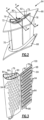
- the illustrated turbine vane 64 includes an outer platform 66, an inner platform 68, and an airfoil that extends between the outer platform 66 and the inner platform 68.
- the airfoil section 70 is hollow and defines a first or leading edge cavity 72 and a second or trailing edge cavity 74. Cooling air is communicated through first and second openings 80 and 82 into corresponding cavities 72 and 74.
- the first cavity 72 includes a baffle 76 and the second cavity 74 includes a flat plate 78.
- Each of the baffle 76 and plate 78 are inserts that direct cooling airflow supplied to each of the corresponding cavities 72, 74. The inserts direct cooling air to impinge on outer walls of each of the corresponding cavities 72, 74.
- the baffle insert 76 defines an interior channel 86 with an open top and includes a plurality of scoops 84 that extend into that interior space.
- the scoops 84 are arranged in a plurality of rows 94 and columns 96 along the length of the baffle 76.
- the rows 94 and columns 96 of scoops 84 are staggered relative to an adjacent row and column. It is also within the contemplation of this disclosure that the scoops 84 could be distributed in other arrangements within either the baffle insert 76 or the flat plate 78.
- the plate 78 includes a first side 98 and a second side 100.
- the plate also includes a plurality of scoops 84 that are arranged in rows 94 and columns 96. Each of the scoops 84 include an opening 90 directed towards the direction of incoming cooling air flow.
- the baffle 76 and the plate 78 are assembled into the corresponding cavity and secured in place to provide and direct cooling air flow that is supplied from the compressor section 24.
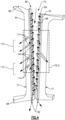
- the leading edge cavity 72 is shown in cross-section including baffle 76.
- the baffle 76 is inserted into the leading edge cavity 72 such that it defines the interior channel 86 and an exterior channel 88 between the baffle 76 and the inner surface 75 of the cavity 72.
- Cooling air indicated by arrow 15 is supplied through the first opening 80 into the interior channel 86.
- Each of the plurality of scoops 84 includes the opening 90 that is directed upward to receive incoming air flow 15.
- the cooling air flow 15 is then directed through each of the plurality of scoops 84 and impinged against the inner surface 75 of the cavity 72. Cooling air flow 15 is then exhausted through film cooling holes 114 or through bottom openings 92 of channel 88 defined between the baffle 76 and inner surface 75 of cavity 72.
- the scoops 84 utilize total pressure, rather than static pressure, to drive the cooling flow 15 against inner surface 75 of cavity 72. This increases the pressure delta across the baffle 76, which increases impingement heat transfer on inner surface 75 of cavity 72.
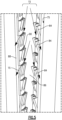
- the trailing edge cavity 74 is smaller and therefore includes the flat plate insert 78.
- the flat plate insert 78 includes a plurality of the scoops 84 that extend from a first side 98. Cooling air 15 directed into the cavity 74 is directed through the scoops 84 from the first side 98 to a second side 100.
- the flat plate insert 78 divides the cavity 74 into a first part 102 and a second part 104.
- the parts 102 and 104 extend the radial length of the cavity 74.
- Each of the scoops 84 includes the opening 90 directed upward to receive incoming cooling airflow 15 and direct that airflow 15 through the flat plate 78 from the first side 98 to the second side 100.
- Cooling air flow directed through the plate 78 is impinged on an inner surface 85 of the cavity 74 within the second part 104, using total pressure as the driving pressure. Air flow that remains within the first part 102 is disturbed to create a turbulent air flow that scrubs against the inner surface 83 of cavity 74 to generate improved heat transfer performance.
- the combination of impingement cooling airflow in the second part 104 and turbulent flow in the first part 102 provide improved heat transfer performance.
- a plurality of film cooling holes 114 extend through the airfoil 70 between each of the cavities 72, 74 to the outer surface 77. Cooling air flows from each cavity 72, 74 to the outer surface 77 of the airfoil 70 to provide film cooling airflow 112.
- the film cooling airflow 112 provides additional cooling along the outer surface of the turbine vane 64. Because the scoops 84 utilize total pressure rather than static pressure to direct cooling airflow, the pressure in channels 88 and 104 is also higher. This results in pressure across the film cooling holes 114 being increased without increasing supply pressure. The increased pressure of film cooling airflow 112 reduces the possibility of back flow through the film cooling holes 114 of hot exhaust gases. Cooling air flow that is not communicated through the film cooling holes 114 is directed through a bottom surface or opening 110 and will either be exhausted or supplied to other features for cooling purposes.
- cooling of the disclosed turbine vane 64 is provided by inserting the baffle 76 and the flat plate 78 into a corresponding one of the cavities 72, 74 within the airfoil 70.
- the baffle 76 and plate 78 include the plurality of scoops 84 configured to direct cooling airflow 15 against the inner surface 75, 85 of the corresponding cavity 72, 74 using total pressure as the driving pressure. Cooling airflow is then directed through the plurality of film cooling holes 114 that define passages between the outer surface 77 of the airfoil 70 and the corresponding cavity 72, 74.
- the example scoops 84 defined within the baffle 76 and the flat plate 78 are stamped features arranged in columns 96 and rows 94 spaced apart such that they provide total desired cooling air flow against the inner surfaces 75, 85 of each cavity 72,74.
- the vanes are fabricated from material that is not favorable of the creation of integrally formed flow directing features. Accordingly, the example inserts 76, 78 both direct cooling airflow for impingement and generate turbulence to improve heat transfer performance.
- baffle inserts 76, 78 were depicted as separate pieces that are typically formed from sheet metal, they may be integral to the component 64 and formed using additive manufacturing or advanced casting techniques.
Landscapes
- Engineering & Computer Science (AREA)
- Mechanical Engineering (AREA)
- General Engineering & Computer Science (AREA)
- Physics & Mathematics (AREA)
- Fluid Mechanics (AREA)
- Turbine Rotor Nozzle Sealing (AREA)
Claims (10)
- Aube directrice de moteur à turbine (64) comprenant :une plate-forme extérieure (66) ;une plate-forme intérieure (68) ;un profil aérodynamique se prolongeant entre la plate-forme extérieure (66) et la plate-forme intérieure (68) et incluant une section de profil aérodynamique creuse (70) définissant une cavité de bord d'attaque (72) en communication avec une source d'air de refroidissement (15) à travers une première ouverture (80) dans la cavité de bord d'attaque (72) et une cavité de bord de fuite (74) en communication avec une source d'air de refroidissement (15) à travers une seconde ouverture (82) dans la cavité de bord de fuite (74), dans laquelle la cavité de bord de fuite (74) est plus petite que la cavité de bord d'attaque (72) ;un insert de déflecteur (76) disposé à l'intérieur de la cavité de bord d'attaque (72) et définissant un canal intérieur (86) avec une partie supérieure ouverte à travers laquelle s'écoule l'air de refroidissement (15), dans laquelle l'insert de déflecteur (76) inclut une pluralité d'écopes d'insert de déflecteur (84) pour diriger l'air de refroidissement (15) à travers l'insert (76) et contre une surface intérieure (75) de la cavité de bord d'attaque (72), caractérisée en ce que la pluralité d'écopes d'insert de déflecteur (84) fait saillie dans le canal intérieur (86) et en ce qu'une ouverture (90) de chacune de la pluralité d'écopes d'insert de déflecteur (84) est dirigée vers un flux entrant d'air de refroidissement (15) pour capturer la pression totale de l'air de refroidissement (15) qui est dirigé pour frapper la surface intérieure (75) de la cavité de bord d'attaque (72) ; etun insert de plaque plate (78) disposé à l'intérieur de la cavité de bord de fuite (74), l'insert de plaque plate (78) incluant un premier côté (98) et un second côté (100) et une pluralité d'écopes d'insert de plaque plate (84) configurés pour diriger le flux d'air de refroidissement (15) à travers l'insert de plaque plate (78) du premier côté (98) vers le second côté (100) contre une surface intérieure (85) de la cavité de bord de fuite (74), dans laquelle la pluralité d'écopes d'insert de plaque plate (84) se prolonge à partir de l'insert de plaque plate (78) sur le premier côté (98) et dans laquelle une ouverture (90) de chacune de la pluralité d'écopes d'insert de plaque plate (84) est dirigée vers un flux entrant d'air de refroidissement (15) pour capturer la pression totale de l'air de refroidissement (15) qui est dirigé pour frapper la surface intérieure (85) de la cavité de bord de fuite (74).
- Aube directrice de moteur à turbine selon la revendication 1, dans laquelle la pluralité d'écopes d'insert de plaque plate (84) est configurée pour générer un flux d'air de refroidissement turbulent (106) sur le premier côté (98) de l'insert de plaque plate (78).
- Aube directrice de moteur à turbine selon une quelconque revendication précédente, dans laquelle l'insert de déflecteur (76) divise la cavité de bord d'attaque (72) en canaux de bord d'attaque séparés (86, 88) comprenant le canal intérieur (86) destiné à recevoir le flux d'air de refroidissement (15) et un canal extérieur (88) défini entre la surface intérieure (75) et l'insert de déflecteur (76) qui reçoit le flux d'air de refroidissement (15) à travers la pluralité d'écopes d'insert de déflecteur (84).
- Aube directrice de moteur à turbine selon une quelconque revendication précédente, dans laquelle la pluralité d'écopes d'insert de déflecteur (84) est disposée en rangées (94) à travers l'insert de déflecteur (76) et chacune des rangées (94) est décalée par rapport aux rangées adjacentes (94).
- Aube directrice de moteur à turbine selon une quelconque revendication précédente, dans laquelle le profil aérodynamique inclut une pluralité de trous de refroidissement par film (114) pour communiquer le flux d'air de refroidissement (15) des cavités de bord d'attaque et de bord de fuite (72 ; 74) à une surface extérieure (77) du profil aérodynamique.
- Moteur à turbine (20), comprenant :une section compresseur (24) ;une section chambre de combustion (26) en communication fluidique avec la section compresseur (24) ;une section turbine (28) en communication fluidique avec la section chambre de combustion (26) ; etune aube directrice de moteur à turbine (64) selon une quelconque revendication précédente.
- Moteur à turbine selon la revendication 6, dans lequel l'aube directrice de moteur à turbine (64) comprend une partie d'un étage stationnaire à l'intérieur de la section turbine (28) .
- Moteur à turbine selon la revendication 6 ou 7, dans lequel la source d'air de refroidissement (15) comprend une partie de la section compresseur (24).
- Procédé de refroidissement d'une aube directrice de moteur à turbine, comprenant :la fourniture d'une aube directrice de moteur à turbine (64) selon l'une quelconque des revendications 1 à 5 ;l'insertion de l'insert de déflecteur (76) dans la cavité de bord d'attaque (72) définie dans la section de profil aérodynamique creux (70) ;l'insertion de l'insert de plaque plate (78) dans la cavité de bord de fuite (74) définie dans la section de profil aérodynamique creux (70) ;la fourniture du flux d'air de refroidissement (15) dans la cavité de bord d'attaque (72) à travers la première ouverture (80) et l'orientation du flux d'air de refroidissement (15) avec la pluralité d'écopes d'insert de déflecteur (84) à travers l'insert de déflecteur (76) et contre la surface intérieure (75) de la cavité de bord d'attaque (72) en utilisant la pression totale capturée pour entraîner le flux à travers la pluralité d'écopes d'insert de déflecteur (84) ; et la fourniture du flux d'air de refroidissement (15) dans la cavité de bord de fuite (74) à travers la seconde ouverture (82) et l'orientation du flux d'air de refroidissement (15) avec la pluralité d'écopes d'insert de plaque plate (84) à travers l'insert de plaque plate (78) et contre la surface intérieure (85) de la cavité de bord de fuite (74) en utilisant la pression totale capturée pour entraîner le flux à travers la pluralité d'écopes d'insert de plaque plate (84).
- Procédé selon la revendication 9 incluant l'écoulement d'air de refroidissement (15) à travers la pluralité de trous de refroidissement par film (114) définissant des passages entre la surface extérieure (77) du profil aérodynamique et les cavités de bord d'attaque et de bord de fuite (72 ; 74) à une pression fournie par le flux d'air de refroidissement (15) dirigé à partir de la pluralité d'écopes d'insert de déflecteur et de plaque plate (84).
Applications Claiming Priority (2)
| Application Number | Priority Date | Filing Date | Title |
|---|---|---|---|
| US201461939302P | 2014-02-13 | 2014-02-13 | |
| PCT/US2015/013161 WO2015123017A1 (fr) | 2014-02-13 | 2015-01-28 | Pièce rapportée de brasseur d'air |
Publications (3)
| Publication Number | Publication Date |
|---|---|
| EP3105437A1 EP3105437A1 (fr) | 2016-12-21 |
| EP3105437A4 EP3105437A4 (fr) | 2017-03-15 |
| EP3105437B1 true EP3105437B1 (fr) | 2025-02-26 |
Family
ID=53800528
Family Applications (1)
| Application Number | Title | Priority Date | Filing Date |
|---|---|---|---|
| EP15748506.1A Active EP3105437B1 (fr) | 2014-02-13 | 2015-01-28 | Refroidissement d'aubes directrices creuses de moteur à turbine |
Country Status (3)
| Country | Link |
|---|---|
| US (1) | US10494939B2 (fr) |
| EP (1) | EP3105437B1 (fr) |
| WO (1) | WO2015123017A1 (fr) |
Families Citing this family (12)
| Publication number | Priority date | Publication date | Assignee | Title |
|---|---|---|---|---|
| US10280841B2 (en) | 2015-12-07 | 2019-05-07 | United Technologies Corporation | Baffle insert for a gas turbine engine component and method of cooling |
| US10337334B2 (en) | 2015-12-07 | 2019-07-02 | United Technologies Corporation | Gas turbine engine component with a baffle insert |
| US10422233B2 (en) | 2015-12-07 | 2019-09-24 | United Technologies Corporation | Baffle insert for a gas turbine engine component and component with baffle insert |
| US10577947B2 (en) | 2015-12-07 | 2020-03-03 | United Technologies Corporation | Baffle insert for a gas turbine engine component |
| KR101797370B1 (ko) * | 2016-07-04 | 2017-12-12 | 두산중공업 주식회사 | 가스터빈 블레이드 |
| US10502093B2 (en) * | 2017-12-13 | 2019-12-10 | Pratt & Whitney Canada Corp. | Turbine shroud cooling |
| US10584596B2 (en) * | 2017-12-22 | 2020-03-10 | United Technologies Corporation | Gas turbine engine components having internal cooling features |
| US10677071B2 (en) * | 2018-04-19 | 2020-06-09 | Raytheon Technologies Corporation | Turbine vane for gas turbine engine |
| CN109340824A (zh) * | 2018-09-19 | 2019-02-15 | 西北工业大学 | 一种具有凹形冷却槽结构的燃烧室火焰筒壁面 |
| US11702941B2 (en) * | 2018-11-09 | 2023-07-18 | Raytheon Technologies Corporation | Airfoil with baffle having flange ring affixed to platform |
| US10774657B2 (en) | 2018-11-23 | 2020-09-15 | Raytheon Technologies Corporation | Baffle assembly for gas turbine engine components |
| US10711620B1 (en) * | 2019-01-14 | 2020-07-14 | General Electric Company | Insert system for an airfoil and method of installing same |
Citations (1)
| Publication number | Priority date | Publication date | Assignee | Title |
|---|---|---|---|---|
| US5816777A (en) * | 1991-11-29 | 1998-10-06 | United Technologies Corporation | Turbine blade cooling |
Family Cites Families (32)
| Publication number | Priority date | Publication date | Assignee | Title |
|---|---|---|---|---|
| US2993337A (en) * | 1959-02-12 | 1961-07-25 | Herbert L Cheeseman | Turbine combustor |
| US3574481A (en) | 1968-05-09 | 1971-04-13 | James A Pyne Jr | Variable area cooled airfoil construction for gas turbines |
| US3767322A (en) | 1971-07-30 | 1973-10-23 | Westinghouse Electric Corp | Internal cooling for turbine vanes |
| US3966357A (en) | 1974-09-25 | 1976-06-29 | General Electric Company | Blade baffle damper |
| US4153386A (en) | 1974-12-11 | 1979-05-08 | United Technologies Corporation | Air cooled turbine vanes |
| US4040767A (en) | 1975-06-02 | 1977-08-09 | United Technologies Corporation | Coolable nozzle guide vane |
| US4025226A (en) | 1975-10-03 | 1977-05-24 | United Technologies Corporation | Air cooled turbine vane |
| US4297077A (en) * | 1979-07-09 | 1981-10-27 | Westinghouse Electric Corp. | Cooled turbine vane |
| GB2163218B (en) * | 1981-07-07 | 1986-07-16 | Rolls Royce | Cooled vane or blade for a gas turbine engine |
| US4542867A (en) | 1983-01-31 | 1985-09-24 | United Technologies Corporation | Internally cooled hollow airfoil |
| US4773593A (en) * | 1987-05-04 | 1988-09-27 | United Technologies Corporation | Coolable thin metal sheet |
| US5667359A (en) | 1988-08-24 | 1997-09-16 | United Technologies Corp. | Clearance control for the turbine of a gas turbine engine |
| US5383766A (en) | 1990-07-09 | 1995-01-24 | United Technologies Corporation | Cooled vane |
| US5405242A (en) | 1990-07-09 | 1995-04-11 | United Technologies Corporation | Cooled vane |
| US5145315A (en) | 1991-09-27 | 1992-09-08 | Westinghouse Electric Corp. | Gas turbine vane cooling air insert |
| US5253976A (en) | 1991-11-19 | 1993-10-19 | General Electric Company | Integrated steam and air cooling for combined cycle gas turbines |
| US5207556A (en) | 1992-04-27 | 1993-05-04 | General Electric Company | Airfoil having multi-passage baffle |
| JPH06129204A (ja) | 1992-10-19 | 1994-05-10 | Mitsubishi Heavy Ind Ltd | ガスタービン静翼の冷却構造 |
| FR2743391B1 (fr) | 1996-01-04 | 1998-02-06 | Snecma | Aube refrigeree de distributeur de turbine |
| US5711650A (en) | 1996-10-04 | 1998-01-27 | Pratt & Whitney Canada, Inc. | Gas turbine airfoil cooling |
| US6193465B1 (en) | 1998-09-28 | 2001-02-27 | General Electric Company | Trapped insert turbine airfoil |
| US6142734A (en) | 1999-04-06 | 2000-11-07 | General Electric Company | Internally grooved turbine wall |
| EP1136651A1 (fr) | 2000-03-22 | 2001-09-26 | Siemens Aktiengesellschaft | Système de refroidissement pour une aube de turbine à gaz |
| US6382908B1 (en) | 2001-01-18 | 2002-05-07 | General Electric Company | Nozzle fillet backside cooling |
| US6554563B2 (en) * | 2001-08-13 | 2003-04-29 | General Electric Company | Tangential flow baffle |
| US6607355B2 (en) | 2001-10-09 | 2003-08-19 | United Technologies Corporation | Turbine airfoil with enhanced heat transfer |
| US7104756B2 (en) | 2004-08-11 | 2006-09-12 | United Technologies Corporation | Temperature tolerant vane assembly |
| US8043057B1 (en) | 2007-12-21 | 2011-10-25 | Florida Turbine Technologies, Inc. | Air cooled turbine airfoil |
| US8393867B2 (en) | 2008-03-31 | 2013-03-12 | United Technologies Corporation | Chambered airfoil cooling |
| US8109724B2 (en) | 2009-03-26 | 2012-02-07 | United Technologies Corporation | Recessed metering standoffs for airfoil baffle |
| US9296039B2 (en) | 2012-04-24 | 2016-03-29 | United Technologies Corporation | Gas turbine engine airfoil impingement cooling |
| EP2907974B1 (fr) * | 2014-02-12 | 2020-10-07 | United Technologies Corporation | Composant et moteur à turbine à gaz associé |
-
2015
- 2015-01-28 EP EP15748506.1A patent/EP3105437B1/fr active Active
- 2015-01-28 WO PCT/US2015/013161 patent/WO2015123017A1/fr not_active Ceased
- 2015-01-28 US US15/114,196 patent/US10494939B2/en active Active
Patent Citations (1)
| Publication number | Priority date | Publication date | Assignee | Title |
|---|---|---|---|---|
| US5816777A (en) * | 1991-11-29 | 1998-10-06 | United Technologies Corporation | Turbine blade cooling |
Also Published As
| Publication number | Publication date |
|---|---|
| US20170234151A1 (en) | 2017-08-17 |
| WO2015123017A1 (fr) | 2015-08-20 |
| US10494939B2 (en) | 2019-12-03 |
| EP3105437A1 (fr) | 2016-12-21 |
| EP3105437A4 (fr) | 2017-03-15 |
Similar Documents
| Publication | Publication Date | Title |
|---|---|---|
| EP3105437B1 (fr) | Refroidissement d'aubes directrices creuses de moteur à turbine | |
| EP2907974B1 (fr) | Composant et moteur à turbine à gaz associé | |
| EP2975217B1 (fr) | Utilisation d'inserts pour équilibrer le transfert de chaleur et les contraintes dans des alliages à haute température | |
| EP2977556B1 (fr) | Pale d'aube, agencement de moteur à turbine à gaz et procédé de refroidissement associé | |
| EP3074606B1 (fr) | Aube de moteur à turbine à gaz présentant un sillon de bord d'attaque et un refroidissement par impact | |
| EP3091184B1 (fr) | Refroidissement du bord d'attaque d'une aube de turbine | |
| EP3063389B1 (fr) | Socles de distribution de films refroidis par un trou | |
| EP3091186B1 (fr) | Composant de moteur à turbine comprenant un passage central de l'enveloppe aligné axialement interrompu par un socle | |
| EP3044418B1 (fr) | Aube de moteur à turbine à gaz avec système de refroidissement à déflecteur à double arceau | |
| EP3034793B1 (fr) | Composant de moteur à turbine à gaz avec capacité de refroidissement accrue | |
| EP3181823B1 (fr) | Procédé et appareil de refroidissement d'une aube de moteur de turbine à gaz | |
| EP3078807B2 (fr) | Passages de refroidissement pour composant de moteur à turbine à gaz | |
| EP3054094B1 (fr) | Chicane d'aube de turbine à gaz et passage de refroidissement en serpentin | |
| EP3266983B1 (fr) | Système de refroidissement d'aube d'une turbine à gaz | |
| US20190301286A1 (en) | Airfoils for gas turbine engines | |
| EP3617454B1 (fr) | Déflecteur avec un collecteur de transfert de chaleur variable | |
| EP3054093B1 (fr) | Agencement de nervures décalées | |
| EP3051066B1 (fr) | Noyau de coulée comprenant des extensions décalées | |
| EP3533971B1 (fr) | Profil aérodynamique à épaisseur de paroi variable | |
| EP3495614B1 (fr) | Composant refroidi de turbine à gaz | |
| US20180038236A1 (en) | Gas turbine engine stator vane baffle arrangement | |
| EP3508693B1 (fr) | Passages d'air de refroidissement séparés pour aube de turbine | |
| EP2977557B1 (fr) | Structure d'aube refroidie et procédé de refroidissement associé | |
| EP3550109B1 (fr) | Composant de moteur à turbine à gaz avec nervure de séparation de flux |
Legal Events
| Date | Code | Title | Description |
|---|---|---|---|
| PUAI | Public reference made under article 153(3) epc to a published international application that has entered the european phase |
Free format text: ORIGINAL CODE: 0009012 |
|
| STAA | Information on the status of an ep patent application or granted ep patent |
Free format text: STATUS: REQUEST FOR EXAMINATION WAS MADE |
|
| 17P | Request for examination filed |
Effective date: 20160913 |
|
| AK | Designated contracting states |
Kind code of ref document: A1 Designated state(s): AL AT BE BG CH CY CZ DE DK EE ES FI FR GB GR HR HU IE IS IT LI LT LU LV MC MK MT NL NO PL PT RO RS SE SI SK SM TR |
|
| AX | Request for extension of the european patent |
Extension state: BA ME |
|
| A4 | Supplementary search report drawn up and despatched |
Effective date: 20170215 |
|
| RIC1 | Information provided on ipc code assigned before grant |
Ipc: F01D 5/18 20060101AFI20170209BHEP Ipc: F01D 9/06 20060101ALI20170209BHEP Ipc: F23R 3/06 20060101ALI20170209BHEP |
|
| DAX | Request for extension of the european patent (deleted) | ||
| STAA | Information on the status of an ep patent application or granted ep patent |
Free format text: STATUS: EXAMINATION IS IN PROGRESS |
|
| 17Q | First examination report despatched |
Effective date: 20190523 |
|
| RAP1 | Party data changed (applicant data changed or rights of an application transferred) |
Owner name: RAYTHEON TECHNOLOGIES CORPORATION |
|
| RAP3 | Party data changed (applicant data changed or rights of an application transferred) |
Owner name: RTX CORPORATION |
|
| GRAP | Despatch of communication of intention to grant a patent |
Free format text: ORIGINAL CODE: EPIDOSNIGR1 |
|
| STAA | Information on the status of an ep patent application or granted ep patent |
Free format text: STATUS: GRANT OF PATENT IS INTENDED |
|
| INTG | Intention to grant announced |
Effective date: 20240927 |
|
| GRAS | Grant fee paid |
Free format text: ORIGINAL CODE: EPIDOSNIGR3 |
|
| GRAA | (expected) grant |
Free format text: ORIGINAL CODE: 0009210 |
|
| STAA | Information on the status of an ep patent application or granted ep patent |
Free format text: STATUS: THE PATENT HAS BEEN GRANTED |
|
| AK | Designated contracting states |
Kind code of ref document: B1 Designated state(s): AL AT BE BG CH CY CZ DE DK EE ES FI FR GB GR HR HU IE IS IT LI LT LU LV MC MK MT NL NO PL PT RO RS SE SI SK SM TR |
|
| REG | Reference to a national code |
Ref country code: GB Ref legal event code: FG4D |
|
| REG | Reference to a national code |
Ref country code: CH Ref legal event code: EP |
|
| REG | Reference to a national code |
Ref country code: DE Ref legal event code: R096 Ref document number: 602015091096 Country of ref document: DE |
|
| REG | Reference to a national code |
Ref country code: IE Ref legal event code: FG4D |
|
| REG | Reference to a national code |
Ref country code: NL Ref legal event code: MP Effective date: 20250226 |
|
| PG25 | Lapsed in a contracting state [announced via postgrant information from national office to epo] |
Ref country code: RS Free format text: LAPSE BECAUSE OF FAILURE TO SUBMIT A TRANSLATION OF THE DESCRIPTION OR TO PAY THE FEE WITHIN THE PRESCRIBED TIME-LIMIT Effective date: 20250526 |
|
| PG25 | Lapsed in a contracting state [announced via postgrant information from national office to epo] |
Ref country code: FI Free format text: LAPSE BECAUSE OF FAILURE TO SUBMIT A TRANSLATION OF THE DESCRIPTION OR TO PAY THE FEE WITHIN THE PRESCRIBED TIME-LIMIT Effective date: 20250226 |
|
| PG25 | Lapsed in a contracting state [announced via postgrant information from national office to epo] |
Ref country code: PL Free format text: LAPSE BECAUSE OF FAILURE TO SUBMIT A TRANSLATION OF THE DESCRIPTION OR TO PAY THE FEE WITHIN THE PRESCRIBED TIME-LIMIT Effective date: 20250226 |
|
| PG25 | Lapsed in a contracting state [announced via postgrant information from national office to epo] |
Ref country code: ES Free format text: LAPSE BECAUSE OF FAILURE TO SUBMIT A TRANSLATION OF THE DESCRIPTION OR TO PAY THE FEE WITHIN THE PRESCRIBED TIME-LIMIT Effective date: 20250226 |
|
| REG | Reference to a national code |
Ref country code: LT Ref legal event code: MG9D |
|
| PG25 | Lapsed in a contracting state [announced via postgrant information from national office to epo] |
Ref country code: IS Free format text: LAPSE BECAUSE OF FAILURE TO SUBMIT A TRANSLATION OF THE DESCRIPTION OR TO PAY THE FEE WITHIN THE PRESCRIBED TIME-LIMIT Effective date: 20250626 Ref country code: NO Free format text: LAPSE BECAUSE OF FAILURE TO SUBMIT A TRANSLATION OF THE DESCRIPTION OR TO PAY THE FEE WITHIN THE PRESCRIBED TIME-LIMIT Effective date: 20250526 |
|
| PG25 | Lapsed in a contracting state [announced via postgrant information from national office to epo] |
Ref country code: NL Free format text: LAPSE BECAUSE OF FAILURE TO SUBMIT A TRANSLATION OF THE DESCRIPTION OR TO PAY THE FEE WITHIN THE PRESCRIBED TIME-LIMIT Effective date: 20250226 |
|
| PG25 | Lapsed in a contracting state [announced via postgrant information from national office to epo] |
Ref country code: HR Free format text: LAPSE BECAUSE OF FAILURE TO SUBMIT A TRANSLATION OF THE DESCRIPTION OR TO PAY THE FEE WITHIN THE PRESCRIBED TIME-LIMIT Effective date: 20250226 |
|
| PG25 | Lapsed in a contracting state [announced via postgrant information from national office to epo] |
Ref country code: LV Free format text: LAPSE BECAUSE OF FAILURE TO SUBMIT A TRANSLATION OF THE DESCRIPTION OR TO PAY THE FEE WITHIN THE PRESCRIBED TIME-LIMIT Effective date: 20250226 Ref country code: PT Free format text: LAPSE BECAUSE OF FAILURE TO SUBMIT A TRANSLATION OF THE DESCRIPTION OR TO PAY THE FEE WITHIN THE PRESCRIBED TIME-LIMIT Effective date: 20250626 |
|
| PG25 | Lapsed in a contracting state [announced via postgrant information from national office to epo] |
Ref country code: GR Free format text: LAPSE BECAUSE OF FAILURE TO SUBMIT A TRANSLATION OF THE DESCRIPTION OR TO PAY THE FEE WITHIN THE PRESCRIBED TIME-LIMIT Effective date: 20250527 Ref country code: BG Free format text: LAPSE BECAUSE OF FAILURE TO SUBMIT A TRANSLATION OF THE DESCRIPTION OR TO PAY THE FEE WITHIN THE PRESCRIBED TIME-LIMIT Effective date: 20250226 |
|
| REG | Reference to a national code |
Ref country code: AT Ref legal event code: MK05 Ref document number: 1770790 Country of ref document: AT Kind code of ref document: T Effective date: 20250226 |
|
| PG25 | Lapsed in a contracting state [announced via postgrant information from national office to epo] |
Ref country code: SE Free format text: LAPSE BECAUSE OF FAILURE TO SUBMIT A TRANSLATION OF THE DESCRIPTION OR TO PAY THE FEE WITHIN THE PRESCRIBED TIME-LIMIT Effective date: 20250226 |
|
| PG25 | Lapsed in a contracting state [announced via postgrant information from national office to epo] |
Ref country code: SM Free format text: LAPSE BECAUSE OF FAILURE TO SUBMIT A TRANSLATION OF THE DESCRIPTION OR TO PAY THE FEE WITHIN THE PRESCRIBED TIME-LIMIT Effective date: 20250226 |
|
| PG25 | Lapsed in a contracting state [announced via postgrant information from national office to epo] |
Ref country code: DK Free format text: LAPSE BECAUSE OF FAILURE TO SUBMIT A TRANSLATION OF THE DESCRIPTION OR TO PAY THE FEE WITHIN THE PRESCRIBED TIME-LIMIT Effective date: 20250226 |
|
| PG25 | Lapsed in a contracting state [announced via postgrant information from national office to epo] |
Ref country code: IT Free format text: LAPSE BECAUSE OF FAILURE TO SUBMIT A TRANSLATION OF THE DESCRIPTION OR TO PAY THE FEE WITHIN THE PRESCRIBED TIME-LIMIT Effective date: 20250226 |
|
| PG25 | Lapsed in a contracting state [announced via postgrant information from national office to epo] |
Ref country code: AT Free format text: LAPSE BECAUSE OF FAILURE TO SUBMIT A TRANSLATION OF THE DESCRIPTION OR TO PAY THE FEE WITHIN THE PRESCRIBED TIME-LIMIT Effective date: 20250226 |
|
| PG25 | Lapsed in a contracting state [announced via postgrant information from national office to epo] |
Ref country code: EE Free format text: LAPSE BECAUSE OF FAILURE TO SUBMIT A TRANSLATION OF THE DESCRIPTION OR TO PAY THE FEE WITHIN THE PRESCRIBED TIME-LIMIT Effective date: 20250226 Ref country code: CZ Free format text: LAPSE BECAUSE OF FAILURE TO SUBMIT A TRANSLATION OF THE DESCRIPTION OR TO PAY THE FEE WITHIN THE PRESCRIBED TIME-LIMIT Effective date: 20250226 |
|
| PG25 | Lapsed in a contracting state [announced via postgrant information from national office to epo] |
Ref country code: RO Free format text: LAPSE BECAUSE OF FAILURE TO SUBMIT A TRANSLATION OF THE DESCRIPTION OR TO PAY THE FEE WITHIN THE PRESCRIBED TIME-LIMIT Effective date: 20250226 |
|
| PG25 | Lapsed in a contracting state [announced via postgrant information from national office to epo] |
Ref country code: SK Free format text: LAPSE BECAUSE OF FAILURE TO SUBMIT A TRANSLATION OF THE DESCRIPTION OR TO PAY THE FEE WITHIN THE PRESCRIBED TIME-LIMIT Effective date: 20250226 |
|
| REG | Reference to a national code |
Ref country code: DE Ref legal event code: R097 Ref document number: 602015091096 Country of ref document: DE |
|
| PLBE | No opposition filed within time limit |
Free format text: ORIGINAL CODE: 0009261 |
|
| STAA | Information on the status of an ep patent application or granted ep patent |
Free format text: STATUS: NO OPPOSITION FILED WITHIN TIME LIMIT |
|
| PGFP | Annual fee paid to national office [announced via postgrant information from national office to epo] |
Ref country code: GB Payment date: 20251220 Year of fee payment: 12 |
|
| PGFP | Annual fee paid to national office [announced via postgrant information from national office to epo] |
Ref country code: FR Payment date: 20251217 Year of fee payment: 12 |
|
| 26N | No opposition filed |
Effective date: 20251127 |