EP3550109B1 - Composant de moteur à turbine à gaz avec nervure de séparation de flux - Google Patents
Composant de moteur à turbine à gaz avec nervure de séparation de flux Download PDFInfo
- Publication number
- EP3550109B1 EP3550109B1 EP19162491.5A EP19162491A EP3550109B1 EP 3550109 B1 EP3550109 B1 EP 3550109B1 EP 19162491 A EP19162491 A EP 19162491A EP 3550109 B1 EP3550109 B1 EP 3550109B1
- Authority
- EP
- European Patent Office
- Prior art keywords
- gas turbine
- turbine engine
- rib
- cooling
- recited
- Prior art date
- Legal status (The legal status is an assumption and is not a legal conclusion. Google has not performed a legal analysis and makes no representation as to the accuracy of the status listed.)
- Active
Links
Images
Classifications
-
- F—MECHANICAL ENGINEERING; LIGHTING; HEATING; WEAPONS; BLASTING
- F01—MACHINES OR ENGINES IN GENERAL; ENGINE PLANTS IN GENERAL; STEAM ENGINES
- F01D—NON-POSITIVE DISPLACEMENT MACHINES OR ENGINES, e.g. STEAM TURBINES
- F01D5/00—Blades; Blade-carrying members; Heating, heat-insulating, cooling or antivibration means on the blades or the members
- F01D5/12—Blades
- F01D5/14—Form or construction
- F01D5/18—Hollow blades, i.e. blades with cooling or heating channels or cavities; Heating, heat-insulating or cooling means on blades
- F01D5/187—Convection cooling
-
- F—MECHANICAL ENGINEERING; LIGHTING; HEATING; WEAPONS; BLASTING
- F01—MACHINES OR ENGINES IN GENERAL; ENGINE PLANTS IN GENERAL; STEAM ENGINES
- F01D—NON-POSITIVE DISPLACEMENT MACHINES OR ENGINES, e.g. STEAM TURBINES
- F01D9/00—Stators
- F01D9/02—Nozzles; Nozzle boxes; Stator blades; Guide conduits, e.g. individual nozzles
-
- F—MECHANICAL ENGINEERING; LIGHTING; HEATING; WEAPONS; BLASTING
- F05—INDEXING SCHEMES RELATING TO ENGINES OR PUMPS IN VARIOUS SUBCLASSES OF CLASSES F01-F04
- F05D—INDEXING SCHEME FOR ASPECTS RELATING TO NON-POSITIVE-DISPLACEMENT MACHINES OR ENGINES, GAS-TURBINES OR JET-PROPULSION PLANTS
- F05D2250/00—Geometry
- F05D2250/10—Two-dimensional
- F05D2250/18—Two-dimensional patterned
- F05D2250/185—Two-dimensional patterned serpentine-like
-
- F—MECHANICAL ENGINEERING; LIGHTING; HEATING; WEAPONS; BLASTING
- F05—INDEXING SCHEMES RELATING TO ENGINES OR PUMPS IN VARIOUS SUBCLASSES OF CLASSES F01-F04
- F05D—INDEXING SCHEME FOR ASPECTS RELATING TO NON-POSITIVE-DISPLACEMENT MACHINES OR ENGINES, GAS-TURBINES OR JET-PROPULSION PLANTS
- F05D2260/00—Function
- F05D2260/20—Heat transfer, e.g. cooling
- F05D2260/201—Heat transfer, e.g. cooling by impingement of a fluid
-
- F—MECHANICAL ENGINEERING; LIGHTING; HEATING; WEAPONS; BLASTING
- F05—INDEXING SCHEMES RELATING TO ENGINES OR PUMPS IN VARIOUS SUBCLASSES OF CLASSES F01-F04
- F05D—INDEXING SCHEME FOR ASPECTS RELATING TO NON-POSITIVE-DISPLACEMENT MACHINES OR ENGINES, GAS-TURBINES OR JET-PROPULSION PLANTS
- F05D2260/00—Function
- F05D2260/20—Heat transfer, e.g. cooling
- F05D2260/202—Heat transfer, e.g. cooling by film cooling
Definitions
- This invention relates to a gas turbine engine, comprising a gas turbine engine component having an internal cooling circuit.
- the internal cooling circuit may include a cooling cavity and a rib that separates the cooling cavity into separate portions.
- Gas turbine engines typically include a compressor section, a combustor section and a turbine section. During operation, air is pressurized in the compressor section and is mixed with fuel and burned in the combustor section to generate hot combustion gases. The hot combustion gases are communicated through the turbine section, which extracts energy from the hot combustion gases to power the compressor section and other gas turbine engine loads.
- gas turbine engine components Because they are commonly exposed to hot combustion gases, many gas turbine engine components employ internal cooling circuits that channel a dedicated cooling fluid for cooling regions of the component. Thermal energy is transferred from the component to the cooling fluid to cool the component.
- US 2012/014808 A1 discloses a prior art near-wall serpentine cooled turbine airfoil.
- US 4 798 515 A discloses prior art variable nozzle area turbine vane cooling.
- WO 2014/175937 A2 discloses a prior art gas turbine engine component having a curved turbulator.
- EP 3514330 discloses a prior art divided baffle for components of gas turbine engines
- the wall circumscribes the cooling cavity.
- the rib is offset from a midspan of the airfoil.
- the rib is defined at a location between 10% and 90% span or between 30% and 70% span of the airfoil.
- a further non-limiting embodiment of any further embodiments includes a plurality of cooling features defined along the wall.
- the plurality of cooling features include pedestals that extend between opposed surfaces of the cooling cavity.
- the plurality of cooling features include trip strips that protrude from surfaces of the cooling cavity.
- the rib is skewed in a radial direction towards one of an inner diameter and an outer diameter of the airfoil.
- the first portion is an outer diameter portion and the second portion is an inner diameter portion of the cooling cavity.
- the outer diameter portion defines a first serpentine passage and the inner diameter portion defines a second serpentine passage.
- the first and second serpentine passages are bounded by the rib.
- the rib is spaced apart from leading and trailing edges of the airfoil.
- the rib extends between leading and trailing edges of the airfoil.
- the first portion is circumferentially offset from the second portion.
- the rib connects between opposing sides of the wall.
- the rib extends in an axial direction inside of the cooling cavity.
- a further non-limiting embodiment of any further embodiments includes a plurality of openings through portions of the wall associated with both the first portion and the second portion, wherein the plurality of openings are film cooling holes.
- a mid-turbine frame includes the airfoil.
- This disclosure relates to a gas turbine engine that comprises a component that includes an internal cooling circuit.
- the cooling circuit employs one or more cooling cavities disposed inside of the component.
- a flow separating rib is positioned to divide the cooling cavity into at least two portions.
- the cooling cavity may be fed with separate cooling fluids at opposite sides of the cavity. These opposite fluid flows are fluidly isolated between the first portion and the second portion by the rib in order to maintain a constant fluid flow within each portion even where pressure differentials may exist between the opposite sides.
- a more evenly cooled part is achieved by maintaining constant fluid flows within each portion of the cooling cavity.
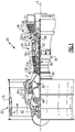
- FIG. 1 schematically illustrates a gas turbine engine 20.
- the gas turbine engine 20 is disclosed herein as a two-spool turbofan that generally incorporates a fan section 22, a compressor section 24, a combustor section 26 and a turbine section 28.
- Alternative engines might include an augmenter section (not shown) among other systems or features.
- the fan section 22 drives air along a bypass flow path B in a bypass duct defined within a nacelle 15, while the compressor section 24 drives air along a core flow path C for compression and communication into the combustor section 26 then expansion through the turbine section 28.
- the exemplary engine 20 generally includes a low speed spool 30 and a high speed spool 32 mounted for rotation about an engine central longitudinal axis A relative to an engine static structure 36 via several bearing systems 38. It should be understood that various bearing systems 38 at various locations may alternatively or additionally be provided, and the location of the bearing systems 38 may be varied as appropriate to the application.
- the low speed spool 30 generally includes an inner shaft 40 that interconnects a fan 42, a first (or low) pressure compressor 44 and a first (or low) pressure turbine 46.
- the inner shaft 40 is connected to the fan 42 through a speed change mechanism, which in exemplary gas turbine engine 20 is illustrated as a geared architecture 48 to drive the fan 42 at a lower speed than the low speed spool 30.
- the high speed spool 32 includes an outer shaft 50 that interconnects a second (or high) pressure compressor 52 and a second (or high) pressure turbine 54.
- a combustor 56 is arranged in exemplary gas turbine 20 between the high pressure compressor 52 and the high pressure turbine 54.
- a mid-turbine frame 57 of the engine static structure 36 is arranged generally between the high pressure turbine 54 and the low pressure turbine 46.
- the mid-turbine frame 57 further supports bearing systems 38 in the turbine section 28.
- the inner shaft 40 and the outer shaft 50 are concentric and rotate via the bearing systems 38 about the engine central longitudinal axis A which is collinear with their longitudinal axes.
- the core airflow is compressed by the low pressure compressor 44 then the high pressure compressor 52, mixed and burned with fuel in the combustor 56, then expanded over the high pressure turbine 54 and low pressure turbine 46.
- the mid-turbine frame 57 includes airfoils 59 which are in the core airflow path C.
- the turbines 46, 54 rotationally drive the respective low speed spool 30 and high speed spool 32 in response to the expansion.
- gear system 48 may be located aft of combustor section 26 or even aft of turbine section 28, and fan section 22 may be positioned forward or aft of the location of gear system 48.
- the engine 20 in one example is a high-bypass geared aircraft engine.
- the engine 20 bypass ratio is greater than about six (6), with an example embodiment being greater than about ten (10)
- the geared architecture 48 is an epicyclic gear train, such as a planetary gear system or other gear system, with a gear reduction ratio of greater than about 2.3
- the low pressure turbine 46 has a pressure ratio that is greater than about five.
- the engine 20 bypass ratio is greater than about ten (10:1)
- the fan diameter is significantly larger than that of the low pressure compressor 44
- the low pressure turbine 46 has a pressure ratio that is greater than about five 5:1.
- Low pressure turbine 46 pressure ratio is pressure measured prior to inlet of low pressure turbine 46 as related to the pressure at the outlet of the low pressure turbine 46 prior to an exhaust nozzle.
- the gear system 48 may be an epicycle gear train, such as a planetary gear system or other gear system, with a gear reduction ratio of greater than about 2.3:1. It should be understood, however, that the above parameters are only exemplary of one embodiment of a geared architecture engine and that the present invention is applicable to other gas turbine engines including direct drive turbofans and turboshafts.
- the fan section 22 of the engine 20 is designed for a particular flight condition -- typically cruise at about 0.8 Mach and about 35,000 feet (10,668 meters).
- the flight condition of 0.8 Mach and 35,000 ft, with the engine at its best fuel consumption - also known as "bucket cruise Thrust Specific Fuel Consumption ('TSFC')" - is the industry standard parameter of lbm of fuel being burned divided by lbf of thrust the engine produces at that minimum point.
- “Low fan pressure ratio” is the pressure ratio across the fan blade alone, without a Fan Exit Guide Vane (“FEGV”) system.
- the low fan pressure ratio as disclosed herein according to one non-limiting embodiment is less than about 1.45.
- Low corrected fan tip speed is the actual fan tip speed in ft/sec divided by an industry standard temperature correction of [(Tram °R) / (518.7 °R)] 0.5 .
- the "Low corrected fan tip speed” as disclosed herein according to one non-limiting embodiment is less than about 1,150 ft/second (350.5 meters/second).
- Each of the compressor section 24 and the turbine section 28 may include alternating rows of rotor assemblies and vane assemblies (shown schematically) that define a plurality of stages 31 of the compressor section 24 and a plurality of stages 33 of the turbine section 28.
- the rotor assemblies can carry a plurality of rotating blades 25, while each vane assembly can carry a plurality of vanes 27 that extend into the core flow path C.
- the blades 25 may either create or extract energy in the form of pressure from the core airflow as it is communicated along the core flow path C.
- the vanes 27 direct the core airflow to the blades 25 to either add or extract energy.
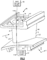
- Figure 2 illustrates a component 60 that is incorporated into a gas turbine engine, such as one or more airfoils including blades 25, vanes 27 or airfoils 59 of the gas turbine engine 20 of Figure 1 .
- the component 60 is represented as a turbine vane, which can be utilized in a stage 33 of the high pressure turbine 54 or low pressure turbine 46, for example.
- the teachings of this disclosure are not limited to turbine vanes and could extend to other components of a gas turbine engine, including but not limited to, other vanes, blades, blade outer air seals (BOAS) (see, for example, the BOAS illustrated in Figure 6 ), or other components such as a blade or vane of the compressor section 24.
- BOAS blade outer air seals
- the component 60 includes an outer platform 62, an inner platform 64, and an airfoil 66 that extends in a chordwise direction X between leading and trailing edges L/E, T/E, in a radial direction R between the outer platform 62 and the inner platform 64, and in a thickness direction T between pressure and suction sides P, S.
- the thickness direction T is generally perpendicular to the chordwise and radial directions X, R.
- the outer platform 62 connects the component 60 to an engine casing (not shown) and the inner platform 64 affixes a radially inboard portion of the component 60 to securely position the component 60 within the core flow path C.
- the component 60 can include one or more internal cooling cavities 72 that are disposed inside of the component 60.
- the cooling cavities 72 extend inside of the airfoil 66 of the component 60.
- one or more cooling cavities may extend inside a body or platform portion of the component, such as in components that do not have an airfoil (e.g., a BOAS, liner, panel, etc.).
- the internal cooling cavities 72 define a cooling circuit 74 for cooling the component 60.
- the illustrated cooling circuit 74 represents but one non-limiting example of many potential cooling circuits.
- the component 60 could be manufactured to include various alternatively shaped and sized cooling passages as part of an internal circuitry within the scope of this disclosure.
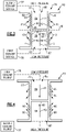
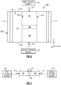
- FIG 3 illustrates a portion of the cooling circuit 74 described in Figure 2 .
- a cross-section through a cooling cavity 72 is depicted.
- the cooling cavity 72 is generally surrounded or circumscribed by a wall 80.
- Opposing sides 90, 92 of the wall 80 define flow boundaries of the cooling cavity 72.
- the wall 80 may embody any of a variety of sizes and shapes within the scope of this disclosure.
- a rib 82 may axially extend inside of the cooling cavity 72 to separate the cooling cavity 72 into a first portion 84 and a second portion 86.
- the first portion 84 is an outer diameter portion of the cooling cavity 72 and the second portion 86 is an inner diameter portion.
- other configurations are also contemplated as being within the scope of this disclosure, including but not limited to circumferentially spaced portions such that the first portion 84 is circumferentially offset from the second portion 86 (see, e.g., Figure 6 ) and axially spaced portions (see, e.g., Figure 7 ).
- Rib 82 can be defined at various span positions of the airfoil 66 relative to the radial direction R. Span position may be relative to the inner platform 64, such as 0% span at the inner platform 64 and 100% span at outer platform 62 (or a tip of blade 25). In an embodiment, rib 82 is defined at about 50% span (i.e., mid-span position). In other embodiments, rib 82 is defined at a location between 10-90% span, or more narrowly between 30-70% span such that rib 82 is radially offset from the mid-span position. The rib 82 can be situated relatively closer to one of the platforms 62, 64 to vary the relative sizes of the first and second portions 84, 86 of the cooling cavity 72.
- the rib 82 extends between the opposing sides 90, 92 of the wall 80 to completely seal and separate the first portion 84 of the cooling cavity 72 from the second portion 86 of the cooling cavity 72. Said another way, the rib 82 is a solid flow separator that fluidly isolates the first portion 84 from the second portion 86 of the cooling cavity 72.
- the rib 82 may be positioned at a mid-span M of the cooling cavity 72.
- the actual location of the rib 82 could vary part-by-part and may depend on pressure differentials that exist between the first portion 84 and the second portion 86 of the cooling cavity 72, among other factors.
- the cooling cavity 72 is a dual-fed cavity that is fed with a cooling fluid at both of its opposite sides (i.e., fed from two distinct locations).
- the first and second portions 84, 86 of the cooling cavity 72 are fed from distinct first and second coolant sources 35, 37 that communicate coolant from different locations.
- the first and second coolant sources 35, 37 are separate and distinct from the component 60.
- the first portion 84 of the cooling cavity 72 is fed with a first cooling fluid F1 from the first coolant source 35, such as a first bleed airflow from a first stage 31A of the compressor section 24 ( Figure 1 ), and the second portion 86 of the cooling cavity 72 may is with a second cooling fluid F2 from the second coolant source 37, such as a second bleed airflow from a second, different stage 31B of the compressor section 24 ( Figure 1 ).
- the cooling fluids F1 and F2 are separate from one another.
- the first and second coolant sources 35, 37 can be defined by various locations or components of the engine 20.
- one of the first and second bleed airflows is supplied by a first stage 31A of the compressor section 24, and another one of the first and second bleed airflows is supplied by a second stage 31B of the compressor section 24.
- the first stage 31A is an upstream stage of high pressure compressor 52 that supplies the cooling fluid F1 at a relatively low pressure, including a forwardmost or intermediate stage
- the second stage 31B is a downstream stage of the high pressure compressor 52 at a relatively higher pressure than the first stage 31A, such as an intermediate or aftmost stage.
- the first coolant source 35 supplies the cooling fluid F1 from the bypass flow path B at a relatively lower pressure and temperature than the second coolant source 37.
- the coolant source 35/37 is a stage 31 of the low pressure compressor 44 or another portion of the engine 20.
- the coolant source 35/37 is a stage 33 of the turbine section 28, such as a first stage 33A and a second stage 33B of the turbine section 28.
- One of first and second stages 33A, 33B can be an upstream stage of the turbine section 28, such as a stage of the high pressure turbine 54, and another one of the first and second stages 33A, 33B can be a downstream stage of the turbine section 28, such as a stage of the low pressure turbine 46.
- an inlet 85 of the first portion 84 of the cooling cavity 72 is positioned in a relatively high pressure area and an inlet 87 of the second portion 86 of the cooling cavity 72 is positioned at a relatively low pressure area.
- an opposite configuration is also possible in which the inlet 85 of the first portion 84 is located at a relatively low pressure area and the inlet 87 of the second portion 86 is within a relatively high pressure area (see Figure 4 ).
- flow of the first and second cooling fluids F1, F2 remains constant within both the first portion 84 and the second portion 86 because these portions are sealed from one another by the rib 82. Maintaining consistent flow in this manner results in relatively consistent Mach numbers, pressure losses, heat transfer and metal temperatures throughout the cooling cavity 72. In other words, the component 60 is more evenly cooled by virtue of the flow separating rib 82.
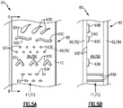
- a plurality of openings 96 may extend through portions of the wall 80 associated with both the first portion 84 and the second portion 86 of the cooling cavity 72.
- the cooling fluids F1, F2 that are circulated in the first and second portions 84, 86, respectively, may be expelled through the openings 96.
- the openings 96 are film cooling holes.
- the openings 96 are slots. Any type of opening may extend through the wall 80 for expelling the cooling fluids F1, F2 from the cooling cavity 72.
- one or more cooling features 93 are defined along the wall 80.
- the cooling features 93 can extend from surfaces of the wall 80, such as one of sides 90, 92, and into the first and/or second portions 84, 86 of the cooling cavity 72.
- the cooling features 93 can be situated to provide additional surface area for convective cooling and/or direct or meter fluid flow within or through localized regions of the first and/or second portions 84, 86.
- Example cooling features 93 can include pedestals 93A extending between opposed surfaces of the cooling cavity 72, for example.
- Other cooling features 93 can include features having a curved or complex geometry such as teardrop shaped features 93B to direct flow through the cooling cavity 72, and sinusoidal shaped features 93C and trip strips 93D protruding from surfaces of the cooling cavity 72 to cause turbulence in the flow of cooling fluid F1/F2.
- Other example cooling features 93 can include recesses such as dimples 93E extending inwardly from surfaces of the wall 80.
- Figure 6 illustrates another component 160 that is incorporated into a gas turbine engine.
- like reference numbers designate like elements where appropriate and reference numerals with the addition of 100 or multiples thereof designate modified elements that are understood to incorporate the same features and benefits of the corresponding original elements.
- the component 160 is represented as a BOAS.
- the BOAS can be situated adjacent to a tip of one the blades 25 and can be utilized to seal or otherwise bound the core flow path C ( Figure 1 ), for example.
- the component 160 includes a body 161 having a radially inner face 163 and a radially outer face 165.
- the radially inner face 163 and the radially outer face 165 extend circumferentially between a first mate face 167 and a second mate face 169 and extend axially between a leading edge 171 and a trailing edge 173.
- a cooling cavity 172 may be disposed inside the body 161.
- the cooling cavity 172 of this embodiment circumferentially extends between the first mate face 167 and the second mate face 169.
- a wall 180 may extend about the cooling cavity 172.
- the cooling cavity 172 is divided into a first portion 184 and a second portion 186 by a rib 182.
- the rib 182 fluidly isolates the first portion 184 from the second portion 186.
- the first portion 184 of the cooling cavity 172 may be fed with a first cooling fluid F1 at a location adjacent to the first mate face 167 and the second portion 186 may be fed with a second cooling fluid F2 at a location adjacent to the second mate face 169.
- the rib 182 is adapted to maintain these split flows at relatively constant flow levels despite potential pressure differentials that may exist between the first mate face 167 and the second mate face 169.
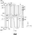
- Figure 8 illustrates another component 260 that can be incorporated into a gas turbine engine.
- the component includes an airfoil 266 that extends in a chordwise direction X between leading and trailing edges L/E, T/E.
- Rib 282 extends in the chordwise direction X between the leading and trailing edges L/E, T/E to fluidly isolate first and second portions 284, 286 such that the cooling fluids F1, F2 do not intermix in cooling cavity 272.
- One or more radially extending ribs 295 extend from walls 280 to establish serpentine passages in first and second portions 284, 286.
- One or more of the ribs 295 can extend or be spaced apart from rib 282 to define sections of the respective serpentine passages, with rib 282 bounding each of the serpentine passages.
- rib 282 has a major component that extends in the chordwise direction X, and ribs 295 each have a major component that extends in a radial direction R.
- An axis E1 of rib 82 can be oriented relative to an axis E2 that extends in the radially direction R through the airfoil 266 to establish a radial angle ⁇ .
- the axis E1 is substantially perpendicular to the axis E2.
- the angle ⁇ is non-perpendicular such that the axis E1 has a component that extends in the radial direction R and the axis E1 is skewed toward an inner diameter 266A or an outer diameter 266B of the airfoil 266.
- the axis E1 can be skewed to adjust a pressure of the cooling fluid F1, F2 that is discharged by opening(s) 296.
- the radial angle ⁇ is between 10-30° or between 70-90°.
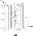
- Figure 9 illustrates yet another component 360 that can be incorporated into a gas turbine engine.
- the component includes an airfoil 366 including a rib 382 that fluidly isolates first and second portions 384, 386 of cooling cavity 372.
- Rib 382 spans between ribs 395 and is spaced apart from leading and trailing edges L/E, T/E.
- Flow of cooling fluids F1, F2 can be directed from inlets 385, 387 and towards the rib 382.
- Wall 380 can include one or more openings 396 to expel the cooling fluids F1, F2 from the first and second portions 384, 386 of the internal cavity 372 to provide film cooling, for example.
Landscapes
- Engineering & Computer Science (AREA)
- Mechanical Engineering (AREA)
- General Engineering & Computer Science (AREA)
- Turbine Rotor Nozzle Sealing (AREA)
Claims (15)
- Moteur à turbine à gaz (20) comprenant un composant (60, 260, 360), le composant comprenant :une paroi (80, 280, 380) qui s'étend autour d'une cavité de refroidissement (72, 272, 372), dans lequel ladite cavité de refroidissement (72, 272, 372) est une cavité à double alimentation qui est alimentée à partir d'au moins deux emplacements différents ; etune nervure (82, 282, 382) qui sépare ladite cavité de refroidissement (72, 272, 372) en une première partie (84, 284, 384) et une seconde partie (86, 286, 386) qui est isolée fluidiquement de ladite première partie (84, 284, 384), dans lequel le composant (60, 260, 360) est un profil aérodynamique (66, 266, 366), caractérisé en ce que :
ladite première partie (84, 284, 384) est alimentée par un premier fluide de refroidissement (F1) provenant d'une première source de fluide de refroidissement (35), et ladite seconde partie (86, 286, 386) est alimentée par un second fluide de refroidissement différent (F2) d'une seconde source de fluide de refroidissement (37), les première et seconde sources de fluide de refroidissement (35, 37) étant séparées et distinctes du composant (60, 260, 360), et lesdites première et seconde sources de fluide de refroidissement (35, 37) sont des étages d'une section de compresseur (24) ou d'une section de turbine (28) du moteur à turbine à gaz (20). - Moteur à turbine à gaz (20) selon la revendication 1, dans lequel ladite paroi (80, 280, 380) circonscrit ladite cavité de refroidissement (72, 272, 372).
- Moteur à turbine à gaz (20) selon la revendication 1 ou 2, dans lequel ladite nervure (82, 282, 382) est décalée par rapport à une mi-portée (M) dudit profil aérodynamique (66, 266, 366).
- Moteur à turbine à gaz (20) selon la revendication 1, 2 ou 3, dans lequel ladite nervure (82, 282, 382) est définie à un emplacement d'une étendue comprise entre 10 % et 90 % ou d'une étendue comprise entre 30 % et 70 % dudit profil aérodynamique (66, 266, 366).
- Moteur à turbine à gaz (20) selon une quelconque revendication précédente, comprenant en outre une pluralité d'éléments de refroidissement (93) définis le long de ladite paroi (80, 280, 380) .
- Moteur à turbine à gaz (20) selon la revendication 5, dans lequel ladite pluralité d'éléments de refroidissement (93) comporte :des socles (93A) qui s'étendent entre des surfaces opposées de ladite cavité de refroidissement (72, 272, 372) ; oudes bandes de déclenchement (93D) qui dépassent des surfaces de ladite cavité de refroidissement (72, 272, 372).
- Moteur à turbine à gaz (20) selon une quelconque revendication précédente, dans lequel ladite nervure (82, 282, 382) est inclinée dans une direction radiale vers l'un d'un diamètre interne (266A) et d'un diamètre externe (266B) dudit profil aérodynamique (66, 266, 366).
- Moteur à turbine à gaz (20) selon une quelconque revendication précédente, dans lequel ladite première partie (84, 284, 384) est une partie de diamètre externe et ladite seconde partie (86, 286, 386) est une partie de diamètre interne de ladite cavité de refroidissement (72, 272, 372).
- Moteur à turbine à gaz (20) selon la revendication 8, dans lequel ladite partie de diamètre externe définit un premier passage en serpentin et ladite partie de diamètre interne définit un second passage en serpentin, les premier et second passages en serpentin étant délimités par ladite nervure (82, 282, 382).
- Moteur à turbine à gaz (20) selon la revendication 8 ou 9, dans lequel ladite nervure (82, 282, 382) est espacée des bords d'attaque et de fuite (L/E, T/E) dudit profil aérodynamique (66, 266, 366),
ou dans lequel ladite nervure (82, 282, 382) s'étend entre des bords d'attaque et de fuite (L/E, T/E) dudit profil aérodynamique (66, 266, 366). - Moteur à turbine à gaz (20) selon une quelconque revendication précédente, dans lequel ladite première partie (84, 284, 384) est circonférentiellement décalée de ladite seconde partie (86, 286, 386).
- Moteur à turbine à gaz (20) selon une quelconque revendication précédente, dans lequel ladite nervure (82, 282, 382) se raccorde entre des côtés opposés (90, 92) de ladite paroi (80, 280, 380).
- Moteur à turbine à gaz (20) selon une quelconque revendication précédente, dans lequel ladite nervure (82, 282, 382) s'étend dans une direction axiale à l'intérieur de ladite cavité de refroidissement (72, 272, 372).
- Moteur à turbine à gaz (20) selon une quelconque revendication précédente, comprenant une pluralité d'ouvertures (96, 296, 396) à travers des parties de ladite paroi (80, 280, 380) associées à la fois à ladite première partie (84, 284, 384) et à ladite seconde partie (86, 286, 386), dans lequel ladite pluralité d'ouvertures (96, 296, 396) sont des trous de refroidissement de film.
- Moteur à turbine à gaz selon une quelconque revendication précédente, comprenant en outre un châssis de turbine intermédiaire (57) qui comporte ledit profil aérodynamique (66, 266, 366) .
Applications Claiming Priority (1)
| Application Number | Priority Date | Filing Date | Title |
|---|---|---|---|
| US15/919,253 US10774655B2 (en) | 2014-04-04 | 2018-03-13 | Gas turbine engine component with flow separating rib |
Publications (2)
| Publication Number | Publication Date |
|---|---|
| EP3550109A1 EP3550109A1 (fr) | 2019-10-09 |
| EP3550109B1 true EP3550109B1 (fr) | 2022-09-28 |
Family
ID=65801978
Family Applications (1)
| Application Number | Title | Priority Date | Filing Date |
|---|---|---|---|
| EP19162491.5A Active EP3550109B1 (fr) | 2018-03-13 | 2019-03-13 | Composant de moteur à turbine à gaz avec nervure de séparation de flux |
Country Status (1)
| Country | Link |
|---|---|
| EP (1) | EP3550109B1 (fr) |
Family Cites Families (4)
| Publication number | Priority date | Publication date | Assignee | Title |
|---|---|---|---|---|
| US4798515A (en) * | 1986-05-19 | 1989-01-17 | The United States Of America As Represented By The Secretary Of The Air Force | Variable nozzle area turbine vane cooling |
| US8535006B2 (en) * | 2010-07-14 | 2013-09-17 | Siemens Energy, Inc. | Near-wall serpentine cooled turbine airfoil |
| JP5931351B2 (ja) * | 2011-05-13 | 2016-06-08 | 三菱重工業株式会社 | タービン静翼 |
| EP2954168B1 (fr) * | 2013-02-05 | 2019-07-03 | United Technologies Corporation | Pièce de turbine à gaz comportant un turbulateur incurvé |
-
2019
- 2019-03-13 EP EP19162491.5A patent/EP3550109B1/fr active Active
Also Published As
| Publication number | Publication date |
|---|---|
| EP3550109A1 (fr) | 2019-10-09 |
Similar Documents
| Publication | Publication Date | Title |
|---|---|---|
| US10774655B2 (en) | Gas turbine engine component with flow separating rib | |
| US10253635B2 (en) | Blade tip cooling arrangement | |
| US10808546B2 (en) | Gas turbine engine airfoil trailing edge suction side cooling | |
| US11035236B2 (en) | Baffle for a component of a gas turbine engine | |
| EP3084136B1 (fr) | Aube rotorique et procédé associé de refroidissement d'une plateforme d'une aube rotorique | |
| EP2944761B1 (fr) | Composant de moteur à turbine à gaz avec circuit de refroidissement de plate-forme | |
| EP2977555B1 (fr) | Plateforme d'aube avec canaux de refroidissement | |
| WO2014047022A1 (fr) | Circuit de refroidissement de composant de moteur à turbine à gaz | |
| EP3181823B1 (fr) | Procédé et appareil de refroidissement d'une aube de moteur de turbine à gaz | |
| EP2937511B1 (fr) | Configuration de passage de refroidissement de profil aérodynamique de turbine à gaz | |
| EP3112596A1 (fr) | Profil aérodynamique de moteur à turbine à gaz avec un passage de refroidissement bi-axial et moteur à turbine à gaz associé | |
| EP3323995B1 (fr) | Profil aérodynamique à déflecteur insérable latéralement | |
| EP3617454A1 (fr) | Déflecteur avec un collecteur de transfert de chaleur variable | |
| EP2927429B1 (fr) | Composant de moteur à turbine à gaz avec nervure de séparation de flux | |
| EP3059391A1 (fr) | Refroidissement de pale de turbine à gaz à l'aide d'une aube de stator amont | |
| EP3550109B1 (fr) | Composant de moteur à turbine à gaz avec nervure de séparation de flux | |
| EP2938831B1 (fr) | Refroidissement de pointe d'une aube de turbine pour un moteur de turbine à gaz | |
| EP3508693B1 (fr) | Passages d'air de refroidissement séparés pour aube de turbine | |
| EP3556997B1 (fr) | Aube avec orifice d'entrée sur la face arrière d'une racine | |
| EP2977557B1 (fr) | Structure d'aube refroidie et procédé de refroidissement associé | |
| EP3575552B1 (fr) | Canal en u optimisé coriolis avec refroidissement de la plateforme | |
| EP3581762B1 (fr) | Virole d'une turbine à gaz avec canaux de refroidissement | |
| EP3575553B1 (fr) | Canal de coriolis optimisé en forme de u avec un passage en forme de drapeau au pied de l'aube |
Legal Events
| Date | Code | Title | Description |
|---|---|---|---|
| PUAI | Public reference made under article 153(3) epc to a published international application that has entered the european phase |
Free format text: ORIGINAL CODE: 0009012 |
|
| STAA | Information on the status of an ep patent application or granted ep patent |
Free format text: STATUS: THE APPLICATION HAS BEEN PUBLISHED |
|
| AK | Designated contracting states |
Kind code of ref document: A1 Designated state(s): AL AT BE BG CH CY CZ DE DK EE ES FI FR GB GR HR HU IE IS IT LI LT LU LV MC MK MT NL NO PL PT RO RS SE SI SK SM TR |
|
| AX | Request for extension of the european patent |
Extension state: BA ME |
|
| STAA | Information on the status of an ep patent application or granted ep patent |
Free format text: STATUS: REQUEST FOR EXAMINATION WAS MADE |
|
| 17P | Request for examination filed |
Effective date: 20200330 |
|
| RBV | Designated contracting states (corrected) |
Designated state(s): AL AT BE BG CH CY CZ DE DK EE ES FI FR GB GR HR HU IE IS IT LI LT LU LV MC MK MT NL NO PL PT RO RS SE SI SK SM TR |
|
| STAA | Information on the status of an ep patent application or granted ep patent |
Free format text: STATUS: EXAMINATION IS IN PROGRESS |
|
| 17Q | First examination report despatched |
Effective date: 20200810 |
|
| RAP1 | Party data changed (applicant data changed or rights of an application transferred) |
Owner name: RAYTHEON TECHNOLOGIES CORPORATION |
|
| GRAP | Despatch of communication of intention to grant a patent |
Free format text: ORIGINAL CODE: EPIDOSNIGR1 |
|
| STAA | Information on the status of an ep patent application or granted ep patent |
Free format text: STATUS: GRANT OF PATENT IS INTENDED |
|
| INTG | Intention to grant announced |
Effective date: 20220408 |
|
| GRAS | Grant fee paid |
Free format text: ORIGINAL CODE: EPIDOSNIGR3 |
|
| GRAA | (expected) grant |
Free format text: ORIGINAL CODE: 0009210 |
|
| STAA | Information on the status of an ep patent application or granted ep patent |
Free format text: STATUS: THE PATENT HAS BEEN GRANTED |
|
| AK | Designated contracting states |
Kind code of ref document: B1 Designated state(s): AL AT BE BG CH CY CZ DE DK EE ES FI FR GB GR HR HU IE IS IT LI LT LU LV MC MK MT NL NO PL PT RO RS SE SI SK SM TR |
|
| REG | Reference to a national code |
Ref country code: GB Ref legal event code: FG4D |
|
| REG | Reference to a national code |
Ref country code: CH Ref legal event code: EP |
|
| REG | Reference to a national code |
Ref country code: DE Ref legal event code: R096 Ref document number: 602019019927 Country of ref document: DE |
|
| REG | Reference to a national code |
Ref country code: AT Ref legal event code: REF Ref document number: 1521354 Country of ref document: AT Kind code of ref document: T Effective date: 20221015 |
|
| REG | Reference to a national code |
Ref country code: IE Ref legal event code: FG4D |
|
| REG | Reference to a national code |
Ref country code: LT Ref legal event code: MG9D |
|
| PG25 | Lapsed in a contracting state [announced via postgrant information from national office to epo] |
Ref country code: SE Free format text: LAPSE BECAUSE OF FAILURE TO SUBMIT A TRANSLATION OF THE DESCRIPTION OR TO PAY THE FEE WITHIN THE PRESCRIBED TIME-LIMIT Effective date: 20220928 Ref country code: RS Free format text: LAPSE BECAUSE OF FAILURE TO SUBMIT A TRANSLATION OF THE DESCRIPTION OR TO PAY THE FEE WITHIN THE PRESCRIBED TIME-LIMIT Effective date: 20220928 Ref country code: NO Free format text: LAPSE BECAUSE OF FAILURE TO SUBMIT A TRANSLATION OF THE DESCRIPTION OR TO PAY THE FEE WITHIN THE PRESCRIBED TIME-LIMIT Effective date: 20221228 Ref country code: LV Free format text: LAPSE BECAUSE OF FAILURE TO SUBMIT A TRANSLATION OF THE DESCRIPTION OR TO PAY THE FEE WITHIN THE PRESCRIBED TIME-LIMIT Effective date: 20220928 Ref country code: LT Free format text: LAPSE BECAUSE OF FAILURE TO SUBMIT A TRANSLATION OF THE DESCRIPTION OR TO PAY THE FEE WITHIN THE PRESCRIBED TIME-LIMIT Effective date: 20220928 Ref country code: FI Free format text: LAPSE BECAUSE OF FAILURE TO SUBMIT A TRANSLATION OF THE DESCRIPTION OR TO PAY THE FEE WITHIN THE PRESCRIBED TIME-LIMIT Effective date: 20220928 |
|
| REG | Reference to a national code |
Ref country code: NL Ref legal event code: MP Effective date: 20220928 |
|
| REG | Reference to a national code |
Ref country code: AT Ref legal event code: MK05 Ref document number: 1521354 Country of ref document: AT Kind code of ref document: T Effective date: 20220928 |
|
| PG25 | Lapsed in a contracting state [announced via postgrant information from national office to epo] |
Ref country code: HR Free format text: LAPSE BECAUSE OF FAILURE TO SUBMIT A TRANSLATION OF THE DESCRIPTION OR TO PAY THE FEE WITHIN THE PRESCRIBED TIME-LIMIT Effective date: 20220928 Ref country code: GR Free format text: LAPSE BECAUSE OF FAILURE TO SUBMIT A TRANSLATION OF THE DESCRIPTION OR TO PAY THE FEE WITHIN THE PRESCRIBED TIME-LIMIT Effective date: 20221229 |
|
| PG25 | Lapsed in a contracting state [announced via postgrant information from national office to epo] |
Ref country code: SM Free format text: LAPSE BECAUSE OF FAILURE TO SUBMIT A TRANSLATION OF THE DESCRIPTION OR TO PAY THE FEE WITHIN THE PRESCRIBED TIME-LIMIT Effective date: 20220928 Ref country code: RO Free format text: LAPSE BECAUSE OF FAILURE TO SUBMIT A TRANSLATION OF THE DESCRIPTION OR TO PAY THE FEE WITHIN THE PRESCRIBED TIME-LIMIT Effective date: 20220928 Ref country code: PT Free format text: LAPSE BECAUSE OF FAILURE TO SUBMIT A TRANSLATION OF THE DESCRIPTION OR TO PAY THE FEE WITHIN THE PRESCRIBED TIME-LIMIT Effective date: 20230130 Ref country code: ES Free format text: LAPSE BECAUSE OF FAILURE TO SUBMIT A TRANSLATION OF THE DESCRIPTION OR TO PAY THE FEE WITHIN THE PRESCRIBED TIME-LIMIT Effective date: 20220928 Ref country code: CZ Free format text: LAPSE BECAUSE OF FAILURE TO SUBMIT A TRANSLATION OF THE DESCRIPTION OR TO PAY THE FEE WITHIN THE PRESCRIBED TIME-LIMIT Effective date: 20220928 Ref country code: AT Free format text: LAPSE BECAUSE OF FAILURE TO SUBMIT A TRANSLATION OF THE DESCRIPTION OR TO PAY THE FEE WITHIN THE PRESCRIBED TIME-LIMIT Effective date: 20220928 |
|
| PG25 | Lapsed in a contracting state [announced via postgrant information from national office to epo] |
Ref country code: SK Free format text: LAPSE BECAUSE OF FAILURE TO SUBMIT A TRANSLATION OF THE DESCRIPTION OR TO PAY THE FEE WITHIN THE PRESCRIBED TIME-LIMIT Effective date: 20220928 Ref country code: PL Free format text: LAPSE BECAUSE OF FAILURE TO SUBMIT A TRANSLATION OF THE DESCRIPTION OR TO PAY THE FEE WITHIN THE PRESCRIBED TIME-LIMIT Effective date: 20220928 Ref country code: IS Free format text: LAPSE BECAUSE OF FAILURE TO SUBMIT A TRANSLATION OF THE DESCRIPTION OR TO PAY THE FEE WITHIN THE PRESCRIBED TIME-LIMIT Effective date: 20230128 Ref country code: EE Free format text: LAPSE BECAUSE OF FAILURE TO SUBMIT A TRANSLATION OF THE DESCRIPTION OR TO PAY THE FEE WITHIN THE PRESCRIBED TIME-LIMIT Effective date: 20220928 |
|
| P01 | Opt-out of the competence of the unified patent court (upc) registered |
Effective date: 20230521 |
|
| REG | Reference to a national code |
Ref country code: DE Ref legal event code: R097 Ref document number: 602019019927 Country of ref document: DE |
|
| PG25 | Lapsed in a contracting state [announced via postgrant information from national office to epo] |
Ref country code: NL Free format text: LAPSE BECAUSE OF FAILURE TO SUBMIT A TRANSLATION OF THE DESCRIPTION OR TO PAY THE FEE WITHIN THE PRESCRIBED TIME-LIMIT Effective date: 20220928 Ref country code: AL Free format text: LAPSE BECAUSE OF FAILURE TO SUBMIT A TRANSLATION OF THE DESCRIPTION OR TO PAY THE FEE WITHIN THE PRESCRIBED TIME-LIMIT Effective date: 20220928 |
|
| PG25 | Lapsed in a contracting state [announced via postgrant information from national office to epo] |
Ref country code: DK Free format text: LAPSE BECAUSE OF FAILURE TO SUBMIT A TRANSLATION OF THE DESCRIPTION OR TO PAY THE FEE WITHIN THE PRESCRIBED TIME-LIMIT Effective date: 20220928 |
|
| PLBE | No opposition filed within time limit |
Free format text: ORIGINAL CODE: 0009261 |
|
| STAA | Information on the status of an ep patent application or granted ep patent |
Free format text: STATUS: NO OPPOSITION FILED WITHIN TIME LIMIT |
|
| 26N | No opposition filed |
Effective date: 20230629 |
|
| PG25 | Lapsed in a contracting state [announced via postgrant information from national office to epo] |
Ref country code: MC Free format text: LAPSE BECAUSE OF FAILURE TO SUBMIT A TRANSLATION OF THE DESCRIPTION OR TO PAY THE FEE WITHIN THE PRESCRIBED TIME-LIMIT Effective date: 20220928 |
|
| REG | Reference to a national code |
Ref country code: CH Ref legal event code: PL |
|
| PG25 | Lapsed in a contracting state [announced via postgrant information from national office to epo] |
Ref country code: SI Free format text: LAPSE BECAUSE OF FAILURE TO SUBMIT A TRANSLATION OF THE DESCRIPTION OR TO PAY THE FEE WITHIN THE PRESCRIBED TIME-LIMIT Effective date: 20220928 |
|
| REG | Reference to a national code |
Ref country code: BE Ref legal event code: MM Effective date: 20230331 |
|
| PG25 | Lapsed in a contracting state [announced via postgrant information from national office to epo] |
Ref country code: LU Free format text: LAPSE BECAUSE OF NON-PAYMENT OF DUE FEES Effective date: 20230313 |
|
| REG | Reference to a national code |
Ref country code: IE Ref legal event code: MM4A |
|
| PG25 | Lapsed in a contracting state [announced via postgrant information from national office to epo] |
Ref country code: LI Free format text: LAPSE BECAUSE OF NON-PAYMENT OF DUE FEES Effective date: 20230331 Ref country code: IE Free format text: LAPSE BECAUSE OF NON-PAYMENT OF DUE FEES Effective date: 20230313 Ref country code: CH Free format text: LAPSE BECAUSE OF NON-PAYMENT OF DUE FEES Effective date: 20230331 |
|
| PG25 | Lapsed in a contracting state [announced via postgrant information from national office to epo] |
Ref country code: BE Free format text: LAPSE BECAUSE OF NON-PAYMENT OF DUE FEES Effective date: 20230331 |
|
| PG25 | Lapsed in a contracting state [announced via postgrant information from national office to epo] |
Ref country code: IT Free format text: LAPSE BECAUSE OF FAILURE TO SUBMIT A TRANSLATION OF THE DESCRIPTION OR TO PAY THE FEE WITHIN THE PRESCRIBED TIME-LIMIT Effective date: 20220928 |
|
| PG25 | Lapsed in a contracting state [announced via postgrant information from national office to epo] |
Ref country code: BG Free format text: LAPSE BECAUSE OF FAILURE TO SUBMIT A TRANSLATION OF THE DESCRIPTION OR TO PAY THE FEE WITHIN THE PRESCRIBED TIME-LIMIT Effective date: 20220928 |
|
| PG25 | Lapsed in a contracting state [announced via postgrant information from national office to epo] |
Ref country code: BG Free format text: LAPSE BECAUSE OF FAILURE TO SUBMIT A TRANSLATION OF THE DESCRIPTION OR TO PAY THE FEE WITHIN THE PRESCRIBED TIME-LIMIT Effective date: 20220928 |
|
| PG25 | Lapsed in a contracting state [announced via postgrant information from national office to epo] |
Ref country code: CY Free format text: LAPSE BECAUSE OF FAILURE TO SUBMIT A TRANSLATION OF THE DESCRIPTION OR TO PAY THE FEE WITHIN THE PRESCRIBED TIME-LIMIT; INVALID AB INITIO Effective date: 20190313 |
|
| PG25 | Lapsed in a contracting state [announced via postgrant information from national office to epo] |
Ref country code: HU Free format text: LAPSE BECAUSE OF FAILURE TO SUBMIT A TRANSLATION OF THE DESCRIPTION OR TO PAY THE FEE WITHIN THE PRESCRIBED TIME-LIMIT; INVALID AB INITIO Effective date: 20190313 |
|
| REG | Reference to a national code |
Ref country code: DE Ref legal event code: R081 Ref document number: 602019019927 Country of ref document: DE Owner name: RTX CORPORATION (N.D.GES.D. STAATES DELAWARE),, US Free format text: FORMER OWNER: RAYTHEON TECHNOLOGIES CORPORATION, FARMINGTON, CT, US |
|
| PG25 | Lapsed in a contracting state [announced via postgrant information from national office to epo] |
Ref country code: TR Free format text: LAPSE BECAUSE OF FAILURE TO SUBMIT A TRANSLATION OF THE DESCRIPTION OR TO PAY THE FEE WITHIN THE PRESCRIBED TIME-LIMIT Effective date: 20220928 |
|
| PGFP | Annual fee paid to national office [announced via postgrant information from national office to epo] |
Ref country code: GB Payment date: 20260220 Year of fee payment: 8 |
|
| PGFP | Annual fee paid to national office [announced via postgrant information from national office to epo] |
Ref country code: DE Payment date: 20260219 Year of fee payment: 8 |
|
| PGFP | Annual fee paid to national office [announced via postgrant information from national office to epo] |
Ref country code: FR Payment date: 20260219 Year of fee payment: 8 |