EP3105434B1 - Kolben mit abreibbarer beschichtung zur erzeugung der geeigneten kontaktgeometrie auf der lauffläche - Google Patents
Kolben mit abreibbarer beschichtung zur erzeugung der geeigneten kontaktgeometrie auf der lauffläche Download PDFInfo
- Publication number
- EP3105434B1 EP3105434B1 EP15704910.7A EP15704910A EP3105434B1 EP 3105434 B1 EP3105434 B1 EP 3105434B1 EP 15704910 A EP15704910 A EP 15704910A EP 3105434 B1 EP3105434 B1 EP 3105434B1
- Authority
- EP
- European Patent Office
- Prior art keywords
- piston
- abradable coating
- pin
- body portion
- shape
- Prior art date
- Legal status (The legal status is an assumption and is not a legal conclusion. Google has not performed a legal analysis and makes no representation as to the accuracy of the status listed.)
- Not-in-force
Links
- 238000000576 coating method Methods 0.000 title claims description 123
- 239000011248 coating agent Substances 0.000 title claims description 122
- 210000000707 wrist Anatomy 0.000 claims description 51
- 238000002485 combustion reaction Methods 0.000 claims description 34
- 238000000034 method Methods 0.000 claims description 30
- CSDREXVUYHZDNP-UHFFFAOYSA-N alumanylidynesilicon Chemical compound [Al].[Si] CSDREXVUYHZDNP-UHFFFAOYSA-N 0.000 claims description 14
- 229910000676 Si alloy Inorganic materials 0.000 claims description 13
- 238000003754 machining Methods 0.000 claims description 13
- 238000004519 manufacturing process Methods 0.000 claims description 9
- 239000007769 metal material Substances 0.000 claims description 7
- 239000000463 material Substances 0.000 claims description 6
- OKTJSMMVPCPJKN-UHFFFAOYSA-N Carbon Chemical compound [C] OKTJSMMVPCPJKN-UHFFFAOYSA-N 0.000 claims description 5
- 229910052782 aluminium Inorganic materials 0.000 claims description 5
- XAGFODPZIPBFFR-UHFFFAOYSA-N aluminium Chemical compound [Al] XAGFODPZIPBFFR-UHFFFAOYSA-N 0.000 claims description 5
- 239000010439 graphite Substances 0.000 claims description 5
- 229910002804 graphite Inorganic materials 0.000 claims description 5
- 229920000642 polymer Polymers 0.000 claims description 5
- 238000005507 spraying Methods 0.000 claims description 5
- 229910052582 BN Inorganic materials 0.000 claims description 4
- PZNSFCLAULLKQX-UHFFFAOYSA-N Boron nitride Chemical compound N#B PZNSFCLAULLKQX-UHFFFAOYSA-N 0.000 claims description 4
- XEEYBQQBJWHFJM-UHFFFAOYSA-N Iron Chemical compound [Fe] XEEYBQQBJWHFJM-UHFFFAOYSA-N 0.000 claims description 4
- 238000005096 rolling process Methods 0.000 claims description 4
- 238000007650 screen-printing Methods 0.000 claims description 4
- 238000007751 thermal spraying Methods 0.000 claims description 3
- 229910052742 iron Inorganic materials 0.000 claims description 2
- 238000001816 cooling Methods 0.000 description 14
- 238000005266 casting Methods 0.000 description 5
- 238000005242 forging Methods 0.000 description 5
- 241000234295 Musa Species 0.000 description 3
- 235000018290 Musa x paradisiaca Nutrition 0.000 description 3
- 229910000831 Steel Inorganic materials 0.000 description 3
- 239000010959 steel Substances 0.000 description 3
- 238000003466 welding Methods 0.000 description 3
- LFQSCWFLJHTTHZ-UHFFFAOYSA-N Ethanol Chemical compound CCO LFQSCWFLJHTTHZ-UHFFFAOYSA-N 0.000 description 2
- 239000012809 cooling fluid Substances 0.000 description 2
- 238000005304 joining Methods 0.000 description 2
- 239000000654 additive Substances 0.000 description 1
- 238000004140 cleaning Methods 0.000 description 1
- 239000000945 filler Substances 0.000 description 1
- 230000006698 induction Effects 0.000 description 1
- 239000000203 mixture Substances 0.000 description 1
- 238000012986 modification Methods 0.000 description 1
- 230000004048 modification Effects 0.000 description 1
- CWQXQMHSOZUFJS-UHFFFAOYSA-N molybdenum disulfide Chemical compound S=[Mo]=S CWQXQMHSOZUFJS-UHFFFAOYSA-N 0.000 description 1
- 229910052982 molybdenum disulfide Inorganic materials 0.000 description 1
- 239000003921 oil Substances 0.000 description 1
- 239000002210 silicon-based material Substances 0.000 description 1
Images


Classifications
-
- F—MECHANICAL ENGINEERING; LIGHTING; HEATING; WEAPONS; BLASTING
- F02—COMBUSTION ENGINES; HOT-GAS OR COMBUSTION-PRODUCT ENGINE PLANTS
- F02F—CYLINDERS, PISTONS OR CASINGS, FOR COMBUSTION ENGINES; ARRANGEMENTS OF SEALINGS IN COMBUSTION ENGINES
- F02F3/00—Pistons
- F02F3/10—Pistons having surface coverings
-
- F—MECHANICAL ENGINEERING; LIGHTING; HEATING; WEAPONS; BLASTING
- F02—COMBUSTION ENGINES; HOT-GAS OR COMBUSTION-PRODUCT ENGINE PLANTS
- F02B—INTERNAL-COMBUSTION PISTON ENGINES; COMBUSTION ENGINES IN GENERAL
- F02B79/00—Running-in of internal-combustion engines
-
- F—MECHANICAL ENGINEERING; LIGHTING; HEATING; WEAPONS; BLASTING
- F16—ENGINEERING ELEMENTS AND UNITS; GENERAL MEASURES FOR PRODUCING AND MAINTAINING EFFECTIVE FUNCTIONING OF MACHINES OR INSTALLATIONS; THERMAL INSULATION IN GENERAL
- F16J—PISTONS; CYLINDERS; SEALINGS
- F16J1/00—Pistons; Trunk pistons; Plungers
- F16J1/10—Connection to driving members
- F16J1/14—Connection to driving members with connecting-rods, i.e. pivotal connections
- F16J1/16—Connection to driving members with connecting-rods, i.e. pivotal connections with gudgeon-pin; Gudgeon-pins
-
- Y—GENERAL TAGGING OF NEW TECHNOLOGICAL DEVELOPMENTS; GENERAL TAGGING OF CROSS-SECTIONAL TECHNOLOGIES SPANNING OVER SEVERAL SECTIONS OF THE IPC; TECHNICAL SUBJECTS COVERED BY FORMER USPC CROSS-REFERENCE ART COLLECTIONS [XRACs] AND DIGESTS
- Y10—TECHNICAL SUBJECTS COVERED BY FORMER USPC
- Y10T—TECHNICAL SUBJECTS COVERED BY FORMER US CLASSIFICATION
- Y10T29/00—Metal working
- Y10T29/49—Method of mechanical manufacture
- Y10T29/49229—Prime mover or fluid pump making
- Y10T29/49249—Piston making
- Y10T29/49256—Piston making with assembly or composite article making
- Y10T29/49263—Piston making with assembly or composite article making by coating or cladding
Definitions
- This invention relates generally to pistons for internal combustion engines, and methods of manufacturing the same.
- Pistons used in internal combustion engines should be designed with appropriate contact geometry for sliding along a cylinder of the internal combustion engine.
- an outside running surface such as the surface of a piston skirt, is machined to an oval shape, in cross-section, to meet such requirements.
- the process of machining the metal material of the piston to the desired oval shape is expensive and requires specialized equipment.
- Wrist pin bores of pistons are also typically formed to an appropriate shape, such as a non-round shape, for accommodating a wrist pin as the piston reciprocates in the cylinder of the engine.
- This profiled wrist pin bore is also expensive to manufacture, due to the process steps and equipment required to machine the metal material.
- a piston with an abradable coating is known from US5469777 or US20110232480 .
- the piston includes a body portion presenting an outer surface, and a portion of the outer surface presents a shape that is not greater than 0.1 mm from a circular shape.
- An abradable coating including an aluminum-silicon alloy is applied to that round portion of the outer surface for rubbing against at least one other component of the internal combustion engine and thus achieving the appropriate contact geometry, for example an oval, asymmetric, or other non-circular shape.
- the invention also provides a piston assembly for use in an internal combustion engine.
- the assembly includes a piston, a connecting rod, and a wrist pin for connecting the piston to the connection rod.
- the piston includes a body portion presenting an outer surface.
- the body portion also includes a crown and pair of pin bosses depending from the crown and spaced from one another about a center axis. Each of the pin bosses defines a pin bore.
- the connecting rod includes a connecting end which is disposed between the pin bosses of the piston.
- the connecting end has a connecting surface defining a pin opening, and the pin opening is axially aligned with the pin bores of the piston.
- the wrist pin extends through the aligned pin bores of the piston and pin opening of the connecting rod for connecting the piston to the connecting rod.
- the wrist pin presents a contact surface facing the pin bosses and the connecting surface of the connecting rod.
- At least one of the pin bosses of the piston, the connecting surface of the connecting rod, and the contact surface of the wrist pin includes a portion presenting a shape which is not greater than 0.1 mm from a circular shape, and an abradable coating including an aluminum-silicon alloy is applied to that portion of the at least one surface.
- Yet another aspect of the invention provides a method of manufacturing a piston for use in an internal combustion engine.
- the method includes providing a body portion of a piston presenting an outer surface, wherein a portion of the outer surface presents a shape which is not greater than 0.1 mm from a circular shape.
- the method further includes applying an abradable coating including an aluminum-silicon alloy to that portion of the outer surface for rubbing against at least one other component of the internal combustion engine.
- Another aspect of the invention provides a method of manufacturing a piston assembly for use in an internal combustion engine, wherein the assembly includes a piston, a connecting rod, and a wrist pin.
- the method includes providing a body portion of the piston, wherein the body portion presents an outer surface, The body portion also includes a crown, and a pair of pin bosses depending from the crown and spaced from one another about a center axis. Each of the pin bosses defines a pin bore.
- the method further includes providing the connecting rod with a connecting end for being disposed between the pin bosses of the piston, wherein the connecting end presents a connecting surface defining a pin opening for being axially aligned with the pin bosses of the piston.
- the method also includes providing the wrist pin for extending through the aligned pin bosses of the piston and pin bore of the connecting rod for connecting the piston to the connecting rod.
- the wrist pin presents a contact surface for facing the pin bosses and the connecting surface of the connecting rod.
- the method further includes applying an abradable coating including an aluminum-silicon alloy to at least one of the pin bosses of the piston, the connecting surface of the connecting rod, and the contact surface of the wrist pin including a portion presenting a shape being not greater than 0.1 mm from a circular shape.
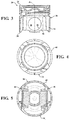
- One aspect of the invention provides a piston 20 with an abradable coating 22 for an internal combustion engine, as shown in the Figures.
- the abradable coating 22 rubs against another component, such as a cylinder liner or wrist pin, and wears down to a suitable shape.
- the abradable coating 22 can be applied to a round running surface of the piston 20 and then wears down to generate an appropriate contact geometry, for example an oval, asymmetric, or other non-circular shape, during the "running-in phase" of operation.
- an appropriate contact geometry for example an oval, asymmetric, or other non-circular shape
- the abradable coating 22 also has the potential to reduce oil consumption, blow-by, emission output, noise, cylinder liner cavitation, and the number of rings from three to two.
- the abradable coating 22 can be applied to many types of pistons, for example diesel, gasoline, ethanol, 2-stroke, and 4-stroke pistons, including pistons with or without a cooling gallery.
- Figures 1-5 illustrate an exemplary diesel piston 20 formed of steel and including a cooling gallery 24
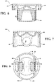
- Figures 6-8 illustrate an exemplary diesel piston 20 formed of steel without a cooling gallery
- Figures 9 and 10 illustrate an exemplary gasoline piston 20 formed of aluminum without a cooling gallery.
- another example of the type of piston to which the abradable coating 22 can be applied is a diesel piston formed of aluminum, with or without a cooling gallery.
- the piston 20 includes a body portion 26 formed of a metal material.
- the metal material is typically an iron-based material or an aluminum-based material, but other materials could be used.
- the body portion 26 extends around a center axis A and longitudinally along the center axis A from an upper end 28 to a lower end 30 .
- the piston 20 also includes a crown 32 extending circumferentially about the center axis A from the upper end 28 toward the lower end 30. In the embodiment of Figures 1-5 , the crown 32 is joined to the remainder of the body portion 26, in this case by welding,
- the crown 32 of the piston 20 defines at least one ring groove 36 extending circumferentially about the center axis A for receiving at least one ring (not shown).
- the piston 20 includes two or three ring grooves 36 .
- Ring lands 38 are disposed adjacent each ring groove 36 and space the ring grooves 36 from one another.
- the outer surface 40 of the ring lands 38 can be machined or otherwise formed to a generally "round" shape, which is a shape that is not greater than 0,1 millimeter (mm) from a circular shape.
- the round shape is less costly to machine than an oval shape or another non-round shape, the oval or other non-round shape is typically desired to achieve appropriate contact geometry between the ring lands 38 and cylinder liner of the internal combustion engine.
- the piston 20 can be formed with or without a cooling gallery 24.
- the piston 20 includes the cooling gallery 24 extending circumferentially around the center axis A between the crown 32 and the remainder of the body portion 26.
- the crown 32 includes a pair of upper ribs 42 spaced from the center axis A and from one another
- the adjacent section of the body portion 26 includes a pair of lower ribs 44 spaced from the center axis A and from one another
- the upper ribs 42 are welded to the lower ribs 44 to form the cooling gallery 24.
- the ribs 42, 44 are friction welded together, but the ribs 42, 44 may be joined using other methods.
- the cooling gallery 24 can contain a cooling fluid to dissipate heat away from the hot crown 32 during use of the piston 20 in the internal combustion engine.
- cooling fluid can be sprayed into the cooling gallery 24 or along an interior surface of the crown 32 to reduce the temperature of the crown 24 during use in the internal combustion engine.
- the pistons 20 of Figures 6-10 are formed without a cooling gallery 24.
- the body portion 26 of the piston 20 further includes a pair of pin bosses 46 spaced from one another about the center axis A and depending from the crown 32 to the lower end 30.
- the outer surface 40 along each of the pin bosses 46 faces inwardly and defines a pin bore 48 for receiving a wrist pin 50 which can be used to connect the piston 20 to a connecting rod 52 , as shown in Figure 11 .
- the outer surface 40 of the pin bosses 46 along the pin bore 48 may be machined or otherwise formed to a generally "round" shape, which is a shape that is not greater than 0.1 mm from a circular shape.
- the body portion 26 also includes a pair of skirt sections 54 spacing the pin bosses 46 from one another about the center axis A and depending from the crown 32 to the lower end 30.
- the outer surface 40 of the skirt sections 54 may also be machined or otherwise formed to a generally "round" shape, which is a shape that is not greater than 0.1 mm from a circular shape.
- the skirt sections 54 present the round shape when the piston 20 completes the casting or forging process, without any machining and before any post-casting or post-forging steps.
- the round shape is less costly to create than the oval shape, the oval shape is typically desired to achieve appropriate contact geometry between the skirt sections 54 and cylinder liner of the internal combustion engine.
- the abradable coating 22 is applied along portions of the outer surface 40 of the piston 20 which initially have the round shape in order to obtain a suitable contact geometry, such as the desired oval, asymmetric, or other non-round shape, without the costly machining process.
- the abradable coating 22 can be formed of various different compositions which wear down when rubbed against another component, such as the cylinder liner or wrist pin.
- the abradable coating includes an aluminum-silicon material.
- the abradable coating 22 is formed of a polymer-based material.
- the abradable coating can also include fillers or additives, such as graphite, hexagonal boron nitride, and/or molybdenum disulfide.
- the abradable coating 22 can consist of a polymer and an aluminum-silicon alloy; an aluminum-silicon alloy and graphite; or an aluminum-silicon alloy and hexagonal boron nitride.
- the abradable coating 22 can be applied to any thickness t, but is typically applied to a thickness t ranging from 20 ⁇ m to 400 ⁇ m.
- the abradable coating 22 is applied to the outer surface 40 of the ring lands 38 which presents the round shape, i.e. the shape being not greater than 0.1 mm from a circular shape
- the abradable coating 22 is typically applied to a thickness t of 50 to 300 ⁇ m along the ring lands 38, and the thickness t is typically approximately uniform along the ring lands 38 when initially applied.
- the abradable coating 22 rubs against the cylinder liner as the piston 20 reciprocates along the cylinder liner.
- an exposed surface 56 of the abradable coating 22 wears down to a more suitable shape, for example an oval shape which is greater than 0.1 mm from a circular shape.
- the thickness t of the abradable coating 22 varies along the ring lands 38 after rubbing against the cylinder liner.
- the abradable coating 22 is applied to the outer surface 40 along the pin bores 48 of the pin bosses 46 which face inwardly and present the round shape, i.e. the shape being not greater than 0.1 mm from a circular shape
- the abradable coating 22 is typically applied to a thickness t of 20 to 30 ⁇ m along the pin bores 48 , and the thickness t is typically approximately uniform along the pin bores 48 when initially applied.
- the wrist pin 50 is disposed in the pin bores 48 to connect the piston 20 to the connecting rod 52 , and the abradable coating 22 rubs against the wrist pin 50 as the piston 20 reciprocates along the cylinder liner.
- the exposed surface 56 of the abradable coating 22 wears down to a more suitable shape, such as an oval or asymmetric shape.
- the worn exposed surface 56 along the pin bores 48 could have a shape which is greater than 0,1 mm from a circular shape, or less than 0.1 mm from a circular shape.
- the abradable coating 22 could achieve a trumpet or banana shape after rubbing against the wrist pin 50.
- the thickness t of the abradable coating 22 typically varies along the pin bores 48 after rubbing against the wrist pin 50.
- the abradable coating 22 is also applied to the outer surface 40 of the skirt sections 54 which presents the round shape, i.e. the shape being not greater than 0.1 mm from a circular shape.
- the abradable coating 22 is typically applied to a thickness t of 100 to 400 ⁇ m along the skirt sections 54 , and the thickness t is typically approximately uniform along the skirt sections 54 when initially applied.
- the abradable coating 22 on the skirt sections 54 rubs against the cylinder liner as the piston 20 reciprocates.
- an exposed surface 56 of the abradable coating 22 wears down to a more suitable shape, for example the oval shape which is greater than 0.1 mm from a circular shape.
- the thickness t of the abradable coating 22 varies along the skirt sections 54 after rubbing against the cylinder liner.
- the piston assembly for use in an internal combustion engine.
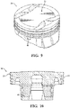
- the piston assembly also includes the wrist pin 50 and connecting rod 52 , as shown in Figure 11 .
- the connecting rod 52 includes a connecting end 58 with a connecting surface 60 defining a pin opening.
- the pin opening is axially aligned with the pin bores 48 of the piston 20
- the wrist pin 50 extends through the aligned pin opening and pin bores 48 to connect the piston 20 to the connecting rod 52.
- the wrist pin 50 presents a contact surface 62 facing the outer surface 40 of the pin bosses 46 and the connecting surface 60 of the connecting rod 52.
- the abradable coating 22 only needs to be applied to the pin bosses 46 or the wrist pin 50 , not both.
- the abradable coating 22 can also, or alternatively, be applied to the connecting surface 60 of the connecting rod 52 and/or the contact surface 62 of the wrist pin 50.
- Figures 11 and 11a illustrate an exemplary embodiment wherein the abradable coating 22 is applied to the contact surface 62 of the wrist pin 50.
- the abradable coating 22 could alternatively be applied to the connecting surface 60 of the connecting rod 52.
- the abradable coating 22 only needs to be applied to the wrist pin 50 or the connecting rod 52 , not both,
- the contact surface 62 of the wrist pin 50 presents a shape being not greater than 0.1 mm from a circular shape, and the abradable coating 22 is applied to this round contact surface 62.
- the abradable coating 22 is typically applied to a thickness t of 20 to 30 ⁇ m along the contact surface 62 , and the thickness t is typically approximately uniform along the contact surface 62 of the wrist pin 50 when initially applied.
- the abradable coating 22 on the wrist pin 50 rubs against the connecting surface 60 of the connecting rod 52 and the outer surface 40 of the pin bosses 46 as the piston 20 reciprocates along the cylinder liner.
- the exposed surface 56 of the abradable coating 22 wears down to a more suitable shape, such as the oval, asymmetric, or other non-round shape, which could be greater than 0.1 mm from a circular shape.
- the thickness t of the abradable coating 22 typically varies along the wrist pin 50 after rubbing against the connecting rod 52 and piston 20, For example, the abradable coating 22 can achieve a trumpet or banana shape after rubbing against the connecting rod 52 and piston 20 .
- the connecting surface 60 of the connecting rod 52 presents a shape being not greater than 0.1 mm from a circular shape, and the abradable coating 22 is applied to this round contact surface 62 of the connecting rod 52.
- the abradable coating 22 is typically applied to a thickness t of 20 to 30 ⁇ m along the connecting surface 60, and the thickness t is typically approximately uniform along the connecting surface 60 of the connecting rod 52 when initially applied.
- the abradable coating 22 on the connecting rod 52 rubs against the contact surface 62 of the wrist pin 50 as the piston 20 reciprocates along the cylinder liner.
- the exposed surface 56 of the abradable coating 22 wears down to a more suitable shape, such as an oval, asymmetric, or other non-round shape which could be greater than 0.1 mm from a circular shape.
- the thickness t of the abradable coating 22 typically varies along the connecting surface 60 after rubbing against the wrist pin 50.
- the abradable coating 22 along the connecting surface 60 can achieve a trumpet or banana shape after rubbing against the wrist pin 50 .
- Yet another aspect of the invention provides a method of manufacturing the piston 20 with the abradable coating 22 with reduced costs by avoiding deliberate machining of the outer surface 40 to a non-round shape.
- the method generally includes providing the body portion 26 of the piston 20, wherein a portion of the outer surface 40 presents the round shape, i.e. the shape which is not greater than 0.1 mm from a circular shape, and applying the abradable coating 22 to that portion of the outer surface 40 for rubbing against at least one other component of the internal combustion engine.
- the step of providing the body portion 26 of the piston 20 typically includes casting or forging a metal material. Various different designs can be achieved during the casting or forging process. In one embodiment, the portions of the outer surface 40 of the piston 20 to which the abradable coating 22 is applied are formed to a shape which is close to the round shape during the casting or forging process.
- the method further includes machining or otherwise forming the portions of the cast or forged structure to which the abradable coating 22 is applied to achieve the round shape, i.e. the shape which is not greater than 0. 1 mm from a circular shape.
- the body portion 26 of the piston 20 is machined to present a cylindrical shape (constant diameter) or barrel or tapered shape (varying diameter) extending from the upper end 28 to the lower end 30, with the round outer surface 40 along the ring lands 38 and the skirt sections 54.
- the pin bores 48 can also be formed by machining to present a cylindrical or barrel shape with the round outer surface 40. It is noted that machining to the round shape is less costly than machining to oval or asymmetric shapes.
- Other portions of the piston 20 without the abradable coating 22 can also be machined to achieve the desired design.
- the method includes joining those pieces together to form the body portion 26.
- the joining step includes friction welding or induction welding the crown 32 to remaining sections of the body portion 26 .
- the method can optionally include another machining step, for example to machine portions of the piston 20 which will include the abradable coating 22, or portions which will be left uncoated.
- the outer surface 40 of the piston 20 is also cleaned or pre-treated, if required, before applying the abradable coating 22 to the outer surface 40.
- the step of applying the abradable coating 22 to the outer surface 40 of the piston 20 typically includes screen printing, rolling, or spraying, for example thermal spraying.
- the method typically is screen printing, rolling, or spraying.
- the abradable coating 22 includes an aluminum-silicon alloy
- the method typically is thermal spraying,
- the abradable coating 22 can be applied to a thickness t varying from 20 to 400 mm, depending on which portion of the piston 20 is coaled, and the thickness t of the abradable coating 22 is typically approximately uniform when first applied.
- the more suitable contact geometry along the outer surface 40 of the piston 20 is then achieved by using the coated piston 20 in the internal combustion engine.
- the abradable coating 22 rubs against at least one other component of the internal combustion engine such that an exposed surface 56 of the abradable coating 22 presents the more suitable shape which could be greater than 0,1 mm from a circular shape.
- the abradable coating 22 is applied to the ring lands 38 or skirt sections 54, the abradable coating 22 rubs against the cylinder liner and can wear down to an oval shape.
- the abradable coating 22 is applied along the pin bores 48 of the pin bosses 46 , then the abradable coating 22 rubs against the wrist pin 50 and can wear down to an oval or asymmetric shape, The thickness t of the abradable coating 22 is no longer uniform after rubbing against another component in the internal combustion engine,
- the method generally includes providing the piston 20, the connecting rod 52 , and the wrist pin 50 , as described above, and applying the abradable coating 22 to at least one of those components.
- the wrist pin 50 and connecting rod 52 can be prepared for the coating process by cleaning, pretreating, or other known methods.
- the wrist pin 50 and connecting rod 52 can also be machined to achieve the round shape, before applying the abradable coating 22.
- the abradable coating 22 is typically applied to an approximately uniform thickness t ranging from 20 to 30 ⁇ m along the connecting rod 52 or wrist pin 50 by spraying. However, other techniques could be used to apply the abradable coating 22.
- method includes applying the abradable coating 22 to the round outer surface 40 of the piston 20 along the ring lands 38, skirt sections 54, and/or pin bosses 46, as described above, and rubbing the abradable coating 22 against another component to achieve the more suitable shape, which could be greater than 0,1 mm from a circular shape.
- the method includes applying the abradable coating 22 to the contact surface 62 of the wrist pin 50, and rubbing the abradable coating 22 against the outer surface 40 of the pin bosses 46 and connecting surface 60 of the connecting rod 52 so that the abradable coating 22 achieves a suitable shape.
- the method includes applying the abradable coating 22 to at least one of the outer surface 40 of the pin bosses 46 and the connecting surface 60 of the connecting rod 52 , and rubbing the abradable coating 22 against the contact surface 62 of the wrist pin 50 so that the abradable coating 22 presents the a suitable shape, which could be greater than 0.1 mm from a circular shape.
Landscapes
- Engineering & Computer Science (AREA)
- General Engineering & Computer Science (AREA)
- Chemical & Material Sciences (AREA)
- Combustion & Propulsion (AREA)
- Mechanical Engineering (AREA)
- Pistons, Piston Rings, And Cylinders (AREA)
Claims (15)
- Kolben (20) zur Verwendung in einem Verbrennungsmotor, umfassend:einen Körperabschnitt (26), der eine Außenfläche (40) aufweist, wobei ein Abschnitt der Außenfläche (40) eine Form aufweist, die um nicht mehr als 0,1 mm von einer runden Form abweicht; undeine Einlaufbeschichtung (22), die auf den Abschnitt der Außenfläche (40) zum Anstreifen an mindestens eine weitere Komponente des Verbrennungsmotors aufgebracht ist,wobei der Körperabschnitt (26) des Kolbens (20) eine Krone (32) einschließt, die mindestens eine sich um eine Mittelachse erstreckende Ringnut (36) und Ringstege (38), von denen jeder angrenzend an eine der Ringnuten (36) angeordnet ist, aufweist, und die Einlaufbeschichtung (22) entlang der Ringstege (38) auf die Außenfläche (40) aufgebracht ist, und/oderwobei der Körperabschnitt (26) eine Krone (32) einschließt, der Körperabschnitt (26) ein Paar von Randleistenteilstücken (54) einschließt, die ein Paar von Bolzenaugen (46) um eine Mittelachse voneinander beabstanden und von der Krone (32) herabhängen, und die Einlaufbeschichtung (22) entlang der Randleistenteilstücke (54) auf die Außenfläche (40) aufgebracht ist, dadurch gekennzeichnet, dass die Einlaufbeschichtung (22) eine Aluminium-Silizium-Legierung einschließt.
- Kolben (20) nach Anspruch 1, wobei der Körperabschnitt (26) eine Krone (32) einschließt, der Körperabschnitt (26) ein Paar von Bolzenaugen (46) einschließt, die von der Krone (32) herabhängen und um eine Mittelachse voneinander beabstandet sind, jedes der Bolzenaugen (46) eine Bolzennabe zum Aufnehmen eines Kolbenbolzens (50) definiert, und die Einlaufbeschichtung (22) entlang der Bolzennabe der Bolzenaugen (46) auf die Außenfläche (40) aufgebracht ist.
- Kolben (20) nach Anspruch 1, wobei die Einlaufbeschichtung (22) mindestens eines von: einem Polymer, Graphit und hexagonalem Bornitrid einschließt.
- Kolben (20) nach Anspruch 1, wobei die Einlaufbeschichtung (22) eine Dicke von 20 bis 400 µm aufweist.
- Kolben (20) nach Anspruch 1, wobei eine freiliegende Fläche der Einlaufbeschichtung (22) eine Form aufweist, die um mehr als 0,1 mm von einer runden Form abweicht, nachdem die Einlaufbeschichtung (22) die mindestens eine weitere Komponente des Verbrennungsmotors angestriffen hat.
- Kolben (20) nach Anspruch 1, wobei der Körperabschnitt (26) aus einem Metallmaterial gebildet ist, wobei das Metallmaterial aus einem eisenbasierten Material und einem aluminiumbasierten Material ausgewählt ist;wobei sich der Körperabschnitt (26) um eine Mittelachse und längs entlang der Mittelachse von einem oberen Ende (28) zu einem unteren Ende (30) erstreckt;wobei der Körperabschnitt (26) eine Krone (32) einschließt, die sich umlaufend um die Mittelachse von dem oberen Ende (28) zu dem unteren Ende (30) erstreckt;wobei die Krone (32) mindestens eine Ringnut (36) definiert, die sich umlaufend um die Mittelachse zum Aufnehmen mindestens eines Rings erstreckt;wobei eine Vielzahl von Ringstegen (38), von denen jeder angrenzend an eine der Ringnuten (36) angeordnet ist;wobei die Außenfläche (40) der Ringstege (38) die Form aufweist, die um nicht mehr als 0,1 mm von einer runden Form abweicht;wobei die Einlaufbeschichtung (22) auf die Außenfläche (40) der Ringstege (38) aufgebracht ist;wobei die Einlaufbeschichtung (22) eine Dicke von 50 bis 300 µm entlang der Ringstege (38) aufweist;
wobei die Einlaufbeschichtung (22) mindestens eines von: einem Polymer, einer Aluminium-Silizium-Legierung, Graphit und hexagonalem Bornitrid einschließt;
wobei der Körperabschnitt (26) ein Paar von Bolzenaugen (46) einschließt, die um
die Mittelachse voneinander beabstandet sind und von der Krone (32) zu dem unteren Ende (30) herabhängen;
wobei jedes der Bolzenaugen (46) eine Bolzennabe zum Aufnehmen eines Kolbenbolzens (50) definiert;
wobei die Außenfläche (40) entlang jedes der Bolzenaugen (46) die Bolzennabe definiert und die Bolzennabe die Form aufweist, die um nicht mehr als 0,1 mm von einer runden Form abweicht;
wobei die Einlaufbeschichtung (22) entlang der Bolzennaben der Bolzenaugen (46) auf die Außenfläche (40) aufgebracht ist;
wobei die Einlaufbeschichtung (22) entlang der Bolzennaben eine Dicke von 20 bis 30 µm aufweist;
wobei der Körperabschnitt (26) ein Paar von Randleistenteilstücken (54) aufweist, die die Bolzenaugen (46) um die Mittelachse voneinander beabstanden und von der unteren Krone (32) zu dem unteren Ende (30) herabhängen;- wobei die Außenfläche (40) der Randleistenteilstücke (54) die Form aufweist, die um nicht mehr als 0,1 mm von einer runden Form abweicht;- eine Einlaufbeschichtung (22) auf die Außenfläche (40) der Randleistenteilstücke (54) aufgebracht ist; und- wobei die Einlaufbeschichtung (22) entlang der Randleistenteilstücke (54) eine Dicke von 100 bis 400 µm aufweist. - Kolbenanordnung zur Verwendung in einem Verbrennungsmotor, umfassend:einen Kolben (20), der einen Körperabschnitt (26) einschließt, der eine Außenfläche (40) aufweist,
wobei der Körperabschnitt (26) eine Krone (32) und ein Paar von Bolzenaugen (46), die von der Krone herabhängen (32) und um eine Mittelachse voneinander beabstandet sind, einschließt, wobei jedes der Bolzenaugen (46) eine Bolzennabe definiert;eine Pleuelstange (52), die einen Pleuelkopf (58) einschließt, der zwischen den Bolzenaugen (46) des Kolbens (20) angeordnet ist;wobei der Pleuelkopf (58) eine Pleuelfläche (60) aufweist, die eine Bolzenöffnung definiert, wobei die Bolzenöffnung zu den Bolzennaben des Kolbens (20) axial fluchtend ausgerichtet ist;einen Kolbenbolzen (50), der sich zum Verbinden des Kolbens (20) mit der Pleuelstange (52) durch die fluchtend ausgerichteten Bolzennaben des Kolbens (20) und Bolzenöffnung der Pleuelstange (52) erstreckt, wobei der Kolbenbolzen (50) eine Kontaktfläche aufweist, die zu der Außenfläche (40) der Bolzenaugen (46) und der Pleuelfläche (60) der Pleuelstange (52) gewandt ist ist;wobei mindestens eines der Außenfläche (40) des Kolbens (20), der Pleuelfläche (60) der Pleuelstange (52) und der Kontaktfläche des Kolbenbolzens (50) einen Abschnitt einschließt, der eine Form aufweist, die um nicht mehr als 0,1 mm von einer runden Form abweicht; und
eine Einlaufbeschichtung (22), die auf den Abschnitt der mindestens einen Fläche aufgebracht ist,dadurch gekennzeichnet, dassdie Einlaufbeschichtung (22) eine Aluminium-Silizium-Legierung einschließt. - Kolbenanordnung nach Anspruch 7, wobei die Einlaufbeschichtung (22) auf die Kontaktfläche des Kolbenbolzens (50) aufgebracht ist.
- Kolbenanordnung nach Anspruch 7, wobei die Einlaufbeschichtung (22) auf mindestens eines von der Außenfläche (40) der Bolzenaugen (46) und der Pleuelfläche (60) der Pleuelstange (52) aufgebracht ist.
- Verfahren zum Herstellen eines Kolbens (20) zur Verwendung in einem Verbrennungsmotor, das die folgenden Schritte umfasst:Bereitstellen eines Körperabschnitts (26) eines Kolbens (20), der eine Außenfläche (40) aufweist, wobei ein Abschnitt der Außenfläche (40) eine Form aufweist, die um nicht mehr als 0,1 mm von einer runden Form abweicht; undAufbringen einer Einlaufbeschichtung (22) auf den Abschnitt der Außenfläche (40) zum Anstreifen an mindestens eine weitere Komponente des Verbrennungsmotors,dadurch gekennzeichnet, dassdie Einlaufbeschichtung (22) eine Aluminium-Silizium-Legierung einschließt.
- Verfahren nach Anspruch 10, wobei der Schritt des Aufbringens der Einlaufbeschichtung (22) mindestens eines von: Siebdrucken, Walzen und Spritzen der Einlaufbeschichtung (22) auf den Abschnitt der Außenfläche (40) einschließt.
- Verfahren nach Anspruch 11, wobei der Schritt des Aufbringens der Einlaufbeschichtung (22) thermisches Spritzen der Einlaufbeschichtung (22) auf den Abschnitt der Außenfläche (40) einschließt.
- Verfahren nach Anspruch 10, wobei der Schritt des Bereitstellens des Körperabschnitts (26) des Kolbens (20) spanendes Bearbeiten des Abschnitts der Außenfläche (40) zu der Form, die um nicht mehr als 0,1 mm von einer runden Form abweicht, einschließt.
- Verfahren zum Herstellen einer Kolbenanordnung zur Verwendung in einem Verbrennungsmotor, das die folgenden Schritte umfasst:Bereitstellen eines Körperabschnitts (26) eines Kolbens (20), wobei der Körperabschnitt (26) eine Außenfläche (40) aufweist, wobei der Körperabschnitt (26) eine Krone (32) und ein Paar von Bolzenaugen (46), die von der Krone (32) herabhängen und um eine Mittelachse voneinander beabstandet sind, einschließt, und wobei jedes der Bolzenaugen (46) eine Bolzennabe definiert;Bereitstellen einer Pleuelstange (52), um zwischen den Bolzenaugen (46) des Kolbens (20) angeordnet zu werden, wobei die Pleuelstange (52) einen Pleuelkopf (58) mit einer Pleuelfläche (60) einschließt, die eine Bolzenöffnung definiert, die dazu eingerichtet ist, zu den Bolzenaugen (46) des Kolbens (20) axial fluchtend ausgerichtet zu werden;Bereitstellen eines Kolbenbolzens (50), der dazu eingerichtet ist, sich zum Verbinden des Kolbens (20) mit der Pleuelstange (52) durch die fluchtend ausgerichteten Bolzenaugen (46) des Kolbens (20) und Bolzennabe der Pleuelstange (52) zu erstrecken, wobei der Kolbenbolzen (50) eine Kontaktfläche aufweist, die dazu eingerichtet ist, zu der Außenfläche (40) der Bolzenaugen (46) und der Pleuelfläche (60) der Pleuelstange (52) gewandt zu sein; undAufbringen einer Einlaufbeschichtung (22) auf mindestens eines der Außenfläche (40) des Kolbens (20), der Pleuelfläche (60) der Pleuelstange (52) und der Kontaktfläche des Kolbenbolzens (50) einschließlich eines Abschnitts, der eine Form aufweist, die um nicht mehr als 0,1 mm von einer runden Form abweicht,dadurch gekennzeichnet, dassdie Einlaufbeschichtung (22) eine Aluminium-Silizium-Legierung einschließt.
- Verfahren nach Anspruch 14, wobei der Schritt des Aufbringens der Einlaufbeschichtung (22) mindestens eines von Siebdrucken, Walzen und Spritzen der Einlaufbeschichtung (22) auf den Abschnitt der Außenfläche (40) einschließt.
Applications Claiming Priority (2)
| Application Number | Priority Date | Filing Date | Title |
|---|---|---|---|
| US201461935518P | 2014-02-04 | 2014-02-04 | |
| PCT/US2015/014409 WO2015120016A1 (en) | 2014-02-04 | 2015-02-04 | Piston with abradable coating to generate appropriate contact geometry on running surface |
Publications (2)
| Publication Number | Publication Date |
|---|---|
| EP3105434A1 EP3105434A1 (de) | 2016-12-21 |
| EP3105434B1 true EP3105434B1 (de) | 2020-04-29 |
Family
ID=53754449
Family Applications (1)
| Application Number | Title | Priority Date | Filing Date |
|---|---|---|---|
| EP15704910.7A Not-in-force EP3105434B1 (de) | 2014-02-04 | 2015-02-04 | Kolben mit abreibbarer beschichtung zur erzeugung der geeigneten kontaktgeometrie auf der lauffläche |
Country Status (3)
| Country | Link |
|---|---|
| US (1) | US9909528B2 (de) |
| EP (1) | EP3105434B1 (de) |
| WO (1) | WO2015120016A1 (de) |
Families Citing this family (5)
| Publication number | Priority date | Publication date | Assignee | Title |
|---|---|---|---|---|
| US9903310B2 (en) * | 2016-05-05 | 2018-02-27 | Mahle International Gmbh | Piston with anti-carbon coating and method for applying an anti-carbon coating on a piston |
| CN106435673A (zh) * | 2016-12-22 | 2017-02-22 | 日照金港活塞有限公司 | 一种内燃机锻钢活塞顶部隔热涂层的制备工艺 |
| US10926330B2 (en) | 2017-02-17 | 2021-02-23 | Tenneco Inc. | Steel piston with metallurgically bonded bushing and method of manufacturing |
| WO2020234856A1 (en) * | 2019-05-22 | 2020-11-26 | Viveknath Richards | Piston design with specialized geometry for internal combustion engine |
| JP7435865B1 (ja) | 2023-03-09 | 2024-02-21 | いすゞ自動車株式会社 | エンジン構造 |
Citations (2)
| Publication number | Priority date | Publication date | Assignee | Title |
|---|---|---|---|---|
| JPH1046361A (ja) * | 1996-08-02 | 1998-02-17 | Toyota Motor Corp | アルミニウム合金摺動部材、その製造方法およびピストン |
| CN201280980Y (zh) * | 2008-10-31 | 2009-07-29 | 山东振挺精工活塞有限公司 | 具有表面隔热层的铝硅合金活塞 |
Family Cites Families (23)
| Publication number | Priority date | Publication date | Assignee | Title |
|---|---|---|---|---|
| FR2076799A5 (de) | 1970-01-28 | 1971-10-15 | Negre Guy | |
| JPS59190455A (ja) * | 1983-04-11 | 1984-10-29 | Mazda Motor Corp | 内燃機関用ピストンのモデルの製造法 |
| DE3418454A1 (de) * | 1984-05-18 | 1985-12-19 | Kolbenschmidt AG, 7107 Neckarsulm | Leichtmetallkolben |
| DE3527032A1 (de) * | 1985-07-27 | 1987-01-29 | Mahle Gmbh | Tauchkolben, insbesondere fuer verbrennungsmotoren |
| US5172626A (en) | 1991-08-22 | 1992-12-22 | General Motors Corporation | Stabilized piston skirt having varying peaks and concave surfaces |
| DE4133546C2 (de) | 1991-10-10 | 2000-12-07 | Mahle Gmbh | Kolben-Zylinderanordnung eines Verbrennungsmotors |
| US5435873A (en) | 1991-11-01 | 1995-07-25 | Decc Technology Partnership, A Limited Partnership Of Which The Decc Company, Inc. Is A General Partner | Method and apparatus for sizing a piston |
| US5266142A (en) | 1991-11-01 | 1993-11-30 | Decc Technology Partnership A Limited Partnership | Coated piston and method and apparatus of coating the same |
| US5435872A (en) | 1991-11-01 | 1995-07-25 | Decc Technology Partnership | Sized coated pistons |
| US5261321A (en) * | 1992-03-06 | 1993-11-16 | Zollner Corporation | Piston having oval shaped crown |
| DE4240050A1 (de) | 1992-11-28 | 1994-06-01 | Mahle Gmbh | Kolben-Zylinder-Vorrichtung eines Verbrennungsmotors |
| US5239955A (en) * | 1993-01-07 | 1993-08-31 | Ford Motor Company | Low friction reciprocating piston assembly |
| US5469777A (en) | 1994-07-05 | 1995-11-28 | Ford Motor Company | Piston assembly having abradable coating |
| US5477820A (en) | 1994-09-29 | 1995-12-26 | Ford Motor Company | Thermal management system for heat engine components |
| DE29801168U1 (de) | 1998-01-24 | 1999-08-12 | Medico Dev Investment Co | Injektionsgerät |
| US5884600A (en) | 1998-02-20 | 1999-03-23 | General Motors Corporation | Aluminum bore engine having wear and scuff-resistant aluminum piston |
| JP4379852B2 (ja) | 2001-06-27 | 2009-12-09 | 本田技研工業株式会社 | アルミ合金製内燃機関用ピストン |
| DE102005061063A1 (de) | 2005-12-21 | 2007-06-28 | Mahle International Gmbh | Kolben für einen Verbrennungsmotor und Verfahren zu seiner Herstellung |
| PL2078060T3 (pl) | 2006-10-30 | 2017-09-29 | Andrew W. Suman | Środek smarny ze ścieralnym suchym filmem i sposób jego nakładania oraz wyrób z niego wykonany |
| US7536945B2 (en) * | 2006-12-29 | 2009-05-26 | Mahle Technology, Inc. | Piston pin for a combustion engine and method for its manufacture |
| US20080163751A1 (en) | 2007-01-09 | 2008-07-10 | Vijay Subramanian | Coated piston and coating method |
| US8408116B2 (en) * | 2009-04-01 | 2013-04-02 | Delaware Capital Formation, Inc. | Method of fitting a piston for use in an internal combustion engine |
| JP5885531B2 (ja) | 2012-02-16 | 2016-03-15 | 日立オートモティブシステムズ株式会社 | 内燃機関のピストン |
-
2015
- 2015-02-04 EP EP15704910.7A patent/EP3105434B1/de not_active Not-in-force
- 2015-02-04 WO PCT/US2015/014409 patent/WO2015120016A1/en not_active Ceased
- 2015-02-04 US US14/613,603 patent/US9909528B2/en not_active Expired - Fee Related
Patent Citations (2)
| Publication number | Priority date | Publication date | Assignee | Title |
|---|---|---|---|---|
| JPH1046361A (ja) * | 1996-08-02 | 1998-02-17 | Toyota Motor Corp | アルミニウム合金摺動部材、その製造方法およびピストン |
| CN201280980Y (zh) * | 2008-10-31 | 2009-07-29 | 山东振挺精工活塞有限公司 | 具有表面隔热层的铝硅合金活塞 |
Also Published As
| Publication number | Publication date |
|---|---|
| US20150219042A1 (en) | 2015-08-06 |
| EP3105434A1 (de) | 2016-12-21 |
| WO2015120016A1 (en) | 2015-08-13 |
| US9909528B2 (en) | 2018-03-06 |
Similar Documents
| Publication | Publication Date | Title |
|---|---|---|
| JP6231781B2 (ja) | シリンダライナ用の厚さの異なるコーティング | |
| US20130025561A1 (en) | Bowl rim and root protection for aluminum pistons | |
| EP3105434B1 (de) | Kolben mit abreibbarer beschichtung zur erzeugung der geeigneten kontaktgeometrie auf der lauffläche | |
| US10359000B2 (en) | Functionally optimized design of a cylinder liner | |
| US20180236555A1 (en) | Steel piston with metallurgically bonded bushing and method of manufacturing | |
| US8857401B2 (en) | Low drag piston | |
| EP3146188B1 (de) | Kolben mit zweiter trapezringnut für hochtemperaturbrennkraftmaschinen | |
| US10655561B2 (en) | Cast light metal piston | |
| JP6455870B2 (ja) | ピストンを受け入れるための切抜き部を有するワークピース | |
| US10428945B2 (en) | Inlaid ring with plated lateral side | |
| EP2964939B1 (de) | Kolben mit kohlenstoffablagerungsschutzbeschichtung und verfahren zur herstellung davon | |
| US20220065188A1 (en) | Internal combustion engine including an element at the cylinder inner wall for scraping off oil carbon | |
| US9599148B2 (en) | Thermal spray coating for connecting rod small end | |
| US10731598B2 (en) | Piston having an undercrown surface with coating and method of manufacture thereof | |
| KR102364805B1 (ko) | 부가적인 기계가공을 통한 피스톤 링-벨트 구조 보강 | |
| CN110431334B (zh) | 用于热力发动机的动力传动装置 | |
| EP4314600B1 (de) | Beschichteter kolbenring für eine brennkraftmaschine | |
| WO2014120657A1 (en) | Steel piston with fourth land guidance and improved friction characteristics | |
| US20160252042A1 (en) | Cylinder Liner | |
| JPS595863A (ja) | ピストン | |
| MAHLE GmbH | Piston design guidelines |
Legal Events
| Date | Code | Title | Description |
|---|---|---|---|
| STAA | Information on the status of an ep patent application or granted ep patent |
Free format text: STATUS: THE INTERNATIONAL PUBLICATION HAS BEEN MADE |
|
| PUAI | Public reference made under article 153(3) epc to a published international application that has entered the european phase |
Free format text: ORIGINAL CODE: 0009012 |
|
| STAA | Information on the status of an ep patent application or granted ep patent |
Free format text: STATUS: REQUEST FOR EXAMINATION WAS MADE |
|
| 17P | Request for examination filed |
Effective date: 20160819 |
|
| AK | Designated contracting states |
Kind code of ref document: A1 Designated state(s): AL AT BE BG CH CY CZ DE DK EE ES FI FR GB GR HR HU IE IS IT LI LT LU LV MC MK MT NL NO PL PT RO RS SE SI SK SM TR |
|
| AX | Request for extension of the european patent |
Extension state: BA ME |
|
| DAX | Request for extension of the european patent (deleted) | ||
| RAP1 | Party data changed (applicant data changed or rights of an application transferred) |
Owner name: FEDERAL-MOGUL LLC |
|
| GRAP | Despatch of communication of intention to grant a patent |
Free format text: ORIGINAL CODE: EPIDOSNIGR1 |
|
| STAA | Information on the status of an ep patent application or granted ep patent |
Free format text: STATUS: GRANT OF PATENT IS INTENDED |
|
| INTG | Intention to grant announced |
Effective date: 20191128 |
|
| GRAS | Grant fee paid |
Free format text: ORIGINAL CODE: EPIDOSNIGR3 |
|
| GRAA | (expected) grant |
Free format text: ORIGINAL CODE: 0009210 |
|
| STAA | Information on the status of an ep patent application or granted ep patent |
Free format text: STATUS: THE PATENT HAS BEEN GRANTED |
|
| RAP1 | Party data changed (applicant data changed or rights of an application transferred) |
Owner name: TENNECO INC. |
|
| AK | Designated contracting states |
Kind code of ref document: B1 Designated state(s): AL AT BE BG CH CY CZ DE DK EE ES FI FR GB GR HR HU IE IS IT LI LT LU LV MC MK MT NL NO PL PT RO RS SE SI SK SM TR |
|
| REG | Reference to a national code |
Ref country code: GB Ref legal event code: FG4D |
|
| REG | Reference to a national code |
Ref country code: CH Ref legal event code: EP |
|
| REG | Reference to a national code |
Ref country code: AT Ref legal event code: REF Ref document number: 1263665 Country of ref document: AT Kind code of ref document: T Effective date: 20200515 |
|
| REG | Reference to a national code |
Ref country code: DE Ref legal event code: R096 Ref document number: 602015051562 Country of ref document: DE |
|
| REG | Reference to a national code |
Ref country code: IE Ref legal event code: FG4D |
|
| REG | Reference to a national code |
Ref country code: NL Ref legal event code: MP Effective date: 20200429 |
|
| REG | Reference to a national code |
Ref country code: LT Ref legal event code: MG4D |
|
| PG25 | Lapsed in a contracting state [announced via postgrant information from national office to epo] |
Ref country code: LT Free format text: LAPSE BECAUSE OF FAILURE TO SUBMIT A TRANSLATION OF THE DESCRIPTION OR TO PAY THE FEE WITHIN THE PRESCRIBED TIME-LIMIT Effective date: 20200429 Ref country code: NO Free format text: LAPSE BECAUSE OF FAILURE TO SUBMIT A TRANSLATION OF THE DESCRIPTION OR TO PAY THE FEE WITHIN THE PRESCRIBED TIME-LIMIT Effective date: 20200729 Ref country code: FI Free format text: LAPSE BECAUSE OF FAILURE TO SUBMIT A TRANSLATION OF THE DESCRIPTION OR TO PAY THE FEE WITHIN THE PRESCRIBED TIME-LIMIT Effective date: 20200429 Ref country code: IS Free format text: LAPSE BECAUSE OF FAILURE TO SUBMIT A TRANSLATION OF THE DESCRIPTION OR TO PAY THE FEE WITHIN THE PRESCRIBED TIME-LIMIT Effective date: 20200829 Ref country code: SE Free format text: LAPSE BECAUSE OF FAILURE TO SUBMIT A TRANSLATION OF THE DESCRIPTION OR TO PAY THE FEE WITHIN THE PRESCRIBED TIME-LIMIT Effective date: 20200429 Ref country code: PT Free format text: LAPSE BECAUSE OF FAILURE TO SUBMIT A TRANSLATION OF THE DESCRIPTION OR TO PAY THE FEE WITHIN THE PRESCRIBED TIME-LIMIT Effective date: 20200831 Ref country code: GR Free format text: LAPSE BECAUSE OF FAILURE TO SUBMIT A TRANSLATION OF THE DESCRIPTION OR TO PAY THE FEE WITHIN THE PRESCRIBED TIME-LIMIT Effective date: 20200730 |
|
| REG | Reference to a national code |
Ref country code: AT Ref legal event code: MK05 Ref document number: 1263665 Country of ref document: AT Kind code of ref document: T Effective date: 20200429 |
|
| PG25 | Lapsed in a contracting state [announced via postgrant information from national office to epo] |
Ref country code: BG Free format text: LAPSE BECAUSE OF FAILURE TO SUBMIT A TRANSLATION OF THE DESCRIPTION OR TO PAY THE FEE WITHIN THE PRESCRIBED TIME-LIMIT Effective date: 20200729 Ref country code: HR Free format text: LAPSE BECAUSE OF FAILURE TO SUBMIT A TRANSLATION OF THE DESCRIPTION OR TO PAY THE FEE WITHIN THE PRESCRIBED TIME-LIMIT Effective date: 20200429 Ref country code: LV Free format text: LAPSE BECAUSE OF FAILURE TO SUBMIT A TRANSLATION OF THE DESCRIPTION OR TO PAY THE FEE WITHIN THE PRESCRIBED TIME-LIMIT Effective date: 20200429 Ref country code: RS Free format text: LAPSE BECAUSE OF FAILURE TO SUBMIT A TRANSLATION OF THE DESCRIPTION OR TO PAY THE FEE WITHIN THE PRESCRIBED TIME-LIMIT Effective date: 20200429 |
|
| PG25 | Lapsed in a contracting state [announced via postgrant information from national office to epo] |
Ref country code: AL Free format text: LAPSE BECAUSE OF FAILURE TO SUBMIT A TRANSLATION OF THE DESCRIPTION OR TO PAY THE FEE WITHIN THE PRESCRIBED TIME-LIMIT Effective date: 20200429 Ref country code: NL Free format text: LAPSE BECAUSE OF FAILURE TO SUBMIT A TRANSLATION OF THE DESCRIPTION OR TO PAY THE FEE WITHIN THE PRESCRIBED TIME-LIMIT Effective date: 20200429 |
|
| PG25 | Lapsed in a contracting state [announced via postgrant information from national office to epo] |
Ref country code: CZ Free format text: LAPSE BECAUSE OF FAILURE TO SUBMIT A TRANSLATION OF THE DESCRIPTION OR TO PAY THE FEE WITHIN THE PRESCRIBED TIME-LIMIT Effective date: 20200429 Ref country code: RO Free format text: LAPSE BECAUSE OF FAILURE TO SUBMIT A TRANSLATION OF THE DESCRIPTION OR TO PAY THE FEE WITHIN THE PRESCRIBED TIME-LIMIT Effective date: 20200429 Ref country code: AT Free format text: LAPSE BECAUSE OF FAILURE TO SUBMIT A TRANSLATION OF THE DESCRIPTION OR TO PAY THE FEE WITHIN THE PRESCRIBED TIME-LIMIT Effective date: 20200429 Ref country code: ES Free format text: LAPSE BECAUSE OF FAILURE TO SUBMIT A TRANSLATION OF THE DESCRIPTION OR TO PAY THE FEE WITHIN THE PRESCRIBED TIME-LIMIT Effective date: 20200429 Ref country code: DK Free format text: LAPSE BECAUSE OF FAILURE TO SUBMIT A TRANSLATION OF THE DESCRIPTION OR TO PAY THE FEE WITHIN THE PRESCRIBED TIME-LIMIT Effective date: 20200429 Ref country code: EE Free format text: LAPSE BECAUSE OF FAILURE TO SUBMIT A TRANSLATION OF THE DESCRIPTION OR TO PAY THE FEE WITHIN THE PRESCRIBED TIME-LIMIT Effective date: 20200429 Ref country code: IT Free format text: LAPSE BECAUSE OF FAILURE TO SUBMIT A TRANSLATION OF THE DESCRIPTION OR TO PAY THE FEE WITHIN THE PRESCRIBED TIME-LIMIT Effective date: 20200429 Ref country code: SM Free format text: LAPSE BECAUSE OF FAILURE TO SUBMIT A TRANSLATION OF THE DESCRIPTION OR TO PAY THE FEE WITHIN THE PRESCRIBED TIME-LIMIT Effective date: 20200429 |
|
| REG | Reference to a national code |
Ref country code: DE Ref legal event code: R097 Ref document number: 602015051562 Country of ref document: DE |
|
| PG25 | Lapsed in a contracting state [announced via postgrant information from national office to epo] |
Ref country code: PL Free format text: LAPSE BECAUSE OF FAILURE TO SUBMIT A TRANSLATION OF THE DESCRIPTION OR TO PAY THE FEE WITHIN THE PRESCRIBED TIME-LIMIT Effective date: 20200429 Ref country code: SK Free format text: LAPSE BECAUSE OF FAILURE TO SUBMIT A TRANSLATION OF THE DESCRIPTION OR TO PAY THE FEE WITHIN THE PRESCRIBED TIME-LIMIT Effective date: 20200429 |
|
| PLBE | No opposition filed within time limit |
Free format text: ORIGINAL CODE: 0009261 |
|
| STAA | Information on the status of an ep patent application or granted ep patent |
Free format text: STATUS: NO OPPOSITION FILED WITHIN TIME LIMIT |
|
| 26N | No opposition filed |
Effective date: 20210201 |
|
| PG25 | Lapsed in a contracting state [announced via postgrant information from national office to epo] |
Ref country code: SI Free format text: LAPSE BECAUSE OF FAILURE TO SUBMIT A TRANSLATION OF THE DESCRIPTION OR TO PAY THE FEE WITHIN THE PRESCRIBED TIME-LIMIT Effective date: 20200429 |
|
| REG | Reference to a national code |
Ref country code: DE Ref legal event code: R119 Ref document number: 602015051562 Country of ref document: DE |
|
| PG25 | Lapsed in a contracting state [announced via postgrant information from national office to epo] |
Ref country code: MC Free format text: LAPSE BECAUSE OF FAILURE TO SUBMIT A TRANSLATION OF THE DESCRIPTION OR TO PAY THE FEE WITHIN THE PRESCRIBED TIME-LIMIT Effective date: 20200429 |
|
| GBPC | Gb: european patent ceased through non-payment of renewal fee |
Effective date: 20210204 |
|
| REG | Reference to a national code |
Ref country code: BE Ref legal event code: MM Effective date: 20210228 |
|
| PG25 | Lapsed in a contracting state [announced via postgrant information from national office to epo] |
Ref country code: CH Free format text: LAPSE BECAUSE OF NON-PAYMENT OF DUE FEES Effective date: 20210228 Ref country code: LI Free format text: LAPSE BECAUSE OF NON-PAYMENT OF DUE FEES Effective date: 20210228 Ref country code: LU Free format text: LAPSE BECAUSE OF NON-PAYMENT OF DUE FEES Effective date: 20210204 |
|
| PG25 | Lapsed in a contracting state [announced via postgrant information from national office to epo] |
Ref country code: DE Free format text: LAPSE BECAUSE OF NON-PAYMENT OF DUE FEES Effective date: 20210901 Ref country code: IE Free format text: LAPSE BECAUSE OF NON-PAYMENT OF DUE FEES Effective date: 20210204 Ref country code: GB Free format text: LAPSE BECAUSE OF NON-PAYMENT OF DUE FEES Effective date: 20210204 Ref country code: FR Free format text: LAPSE BECAUSE OF NON-PAYMENT OF DUE FEES Effective date: 20210228 |
|
| PG25 | Lapsed in a contracting state [announced via postgrant information from national office to epo] |
Ref country code: BE Free format text: LAPSE BECAUSE OF NON-PAYMENT OF DUE FEES Effective date: 20210228 |
|
| PG25 | Lapsed in a contracting state [announced via postgrant information from national office to epo] |
Ref country code: HU Free format text: LAPSE BECAUSE OF FAILURE TO SUBMIT A TRANSLATION OF THE DESCRIPTION OR TO PAY THE FEE WITHIN THE PRESCRIBED TIME-LIMIT; INVALID AB INITIO Effective date: 20150204 |
|
| PG25 | Lapsed in a contracting state [announced via postgrant information from national office to epo] |
Ref country code: CY Free format text: LAPSE BECAUSE OF FAILURE TO SUBMIT A TRANSLATION OF THE DESCRIPTION OR TO PAY THE FEE WITHIN THE PRESCRIBED TIME-LIMIT Effective date: 20200429 |
|
| PG25 | Lapsed in a contracting state [announced via postgrant information from national office to epo] |
Ref country code: MK Free format text: LAPSE BECAUSE OF FAILURE TO SUBMIT A TRANSLATION OF THE DESCRIPTION OR TO PAY THE FEE WITHIN THE PRESCRIBED TIME-LIMIT Effective date: 20200429 |
|
| PG25 | Lapsed in a contracting state [announced via postgrant information from national office to epo] |
Ref country code: TR Free format text: LAPSE BECAUSE OF FAILURE TO SUBMIT A TRANSLATION OF THE DESCRIPTION OR TO PAY THE FEE WITHIN THE PRESCRIBED TIME-LIMIT Effective date: 20200429 |
|
| PG25 | Lapsed in a contracting state [announced via postgrant information from national office to epo] |
Ref country code: MT Free format text: LAPSE BECAUSE OF FAILURE TO SUBMIT A TRANSLATION OF THE DESCRIPTION OR TO PAY THE FEE WITHIN THE PRESCRIBED TIME-LIMIT Effective date: 20200429 |