EP3105434B1 - Piston with abradable coating to generate appropriate contact geometry on running surface - Google Patents
Piston with abradable coating to generate appropriate contact geometry on running surface Download PDFInfo
- Publication number
- EP3105434B1 EP3105434B1 EP15704910.7A EP15704910A EP3105434B1 EP 3105434 B1 EP3105434 B1 EP 3105434B1 EP 15704910 A EP15704910 A EP 15704910A EP 3105434 B1 EP3105434 B1 EP 3105434B1
- Authority
- EP
- European Patent Office
- Prior art keywords
- piston
- abradable coating
- pin
- body portion
- shape
- Prior art date
- Legal status (The legal status is an assumption and is not a legal conclusion. Google has not performed a legal analysis and makes no representation as to the accuracy of the status listed.)
- Active
Links
Images


Classifications
-
- F—MECHANICAL ENGINEERING; LIGHTING; HEATING; WEAPONS; BLASTING
- F02—COMBUSTION ENGINES; HOT-GAS OR COMBUSTION-PRODUCT ENGINE PLANTS
- F02F—CYLINDERS, PISTONS OR CASINGS, FOR COMBUSTION ENGINES; ARRANGEMENTS OF SEALINGS IN COMBUSTION ENGINES
- F02F3/00—Pistons
- F02F3/10—Pistons having surface coverings
-
- F—MECHANICAL ENGINEERING; LIGHTING; HEATING; WEAPONS; BLASTING
- F02—COMBUSTION ENGINES; HOT-GAS OR COMBUSTION-PRODUCT ENGINE PLANTS
- F02B—INTERNAL-COMBUSTION PISTON ENGINES; COMBUSTION ENGINES IN GENERAL
- F02B79/00—Running-in of internal-combustion engines
-
- F—MECHANICAL ENGINEERING; LIGHTING; HEATING; WEAPONS; BLASTING
- F16—ENGINEERING ELEMENTS AND UNITS; GENERAL MEASURES FOR PRODUCING AND MAINTAINING EFFECTIVE FUNCTIONING OF MACHINES OR INSTALLATIONS; THERMAL INSULATION IN GENERAL
- F16J—PISTONS; CYLINDERS; SEALINGS
- F16J1/00—Pistons; Trunk pistons; Plungers
- F16J1/10—Connection to driving members
- F16J1/14—Connection to driving members with connecting-rods, i.e. pivotal connections
- F16J1/16—Connection to driving members with connecting-rods, i.e. pivotal connections with gudgeon-pin; Gudgeon-pins
-
- Y—GENERAL TAGGING OF NEW TECHNOLOGICAL DEVELOPMENTS; GENERAL TAGGING OF CROSS-SECTIONAL TECHNOLOGIES SPANNING OVER SEVERAL SECTIONS OF THE IPC; TECHNICAL SUBJECTS COVERED BY FORMER USPC CROSS-REFERENCE ART COLLECTIONS [XRACs] AND DIGESTS
- Y10—TECHNICAL SUBJECTS COVERED BY FORMER USPC
- Y10T—TECHNICAL SUBJECTS COVERED BY FORMER US CLASSIFICATION
- Y10T29/00—Metal working
- Y10T29/49—Method of mechanical manufacture
- Y10T29/49229—Prime mover or fluid pump making
- Y10T29/49249—Piston making
- Y10T29/49256—Piston making with assembly or composite article making
- Y10T29/49263—Piston making with assembly or composite article making by coating or cladding
Definitions
- This invention relates generally to pistons for internal combustion engines, and methods of manufacturing the same.
- Pistons used in internal combustion engines should be designed with appropriate contact geometry for sliding along a cylinder of the internal combustion engine.
- an outside running surface such as the surface of a piston skirt, is machined to an oval shape, in cross-section, to meet such requirements.
- the process of machining the metal material of the piston to the desired oval shape is expensive and requires specialized equipment.
- Wrist pin bores of pistons are also typically formed to an appropriate shape, such as a non-round shape, for accommodating a wrist pin as the piston reciprocates in the cylinder of the engine.
- This profiled wrist pin bore is also expensive to manufacture, due to the process steps and equipment required to machine the metal material.
- a piston with an abradable coating is known from US5469777 or US20110232480 .
- the piston includes a body portion presenting an outer surface, and a portion of the outer surface presents a shape that is not greater than 0.1 mm from a circular shape.
- An abradable coating including an aluminum-silicon alloy is applied to that round portion of the outer surface for rubbing against at least one other component of the internal combustion engine and thus achieving the appropriate contact geometry, for example an oval, asymmetric, or other non-circular shape.
- the invention also provides a piston assembly for use in an internal combustion engine.
- the assembly includes a piston, a connecting rod, and a wrist pin for connecting the piston to the connection rod.
- the piston includes a body portion presenting an outer surface.
- the body portion also includes a crown and pair of pin bosses depending from the crown and spaced from one another about a center axis. Each of the pin bosses defines a pin bore.
- the connecting rod includes a connecting end which is disposed between the pin bosses of the piston.
- the connecting end has a connecting surface defining a pin opening, and the pin opening is axially aligned with the pin bores of the piston.
- the wrist pin extends through the aligned pin bores of the piston and pin opening of the connecting rod for connecting the piston to the connecting rod.
- the wrist pin presents a contact surface facing the pin bosses and the connecting surface of the connecting rod.
- At least one of the pin bosses of the piston, the connecting surface of the connecting rod, and the contact surface of the wrist pin includes a portion presenting a shape which is not greater than 0.1 mm from a circular shape, and an abradable coating including an aluminum-silicon alloy is applied to that portion of the at least one surface.
- Yet another aspect of the invention provides a method of manufacturing a piston for use in an internal combustion engine.
- the method includes providing a body portion of a piston presenting an outer surface, wherein a portion of the outer surface presents a shape which is not greater than 0.1 mm from a circular shape.
- the method further includes applying an abradable coating including an aluminum-silicon alloy to that portion of the outer surface for rubbing against at least one other component of the internal combustion engine.
- Another aspect of the invention provides a method of manufacturing a piston assembly for use in an internal combustion engine, wherein the assembly includes a piston, a connecting rod, and a wrist pin.
- the method includes providing a body portion of the piston, wherein the body portion presents an outer surface, The body portion also includes a crown, and a pair of pin bosses depending from the crown and spaced from one another about a center axis. Each of the pin bosses defines a pin bore.
- the method further includes providing the connecting rod with a connecting end for being disposed between the pin bosses of the piston, wherein the connecting end presents a connecting surface defining a pin opening for being axially aligned with the pin bosses of the piston.
- the method also includes providing the wrist pin for extending through the aligned pin bosses of the piston and pin bore of the connecting rod for connecting the piston to the connecting rod.
- the wrist pin presents a contact surface for facing the pin bosses and the connecting surface of the connecting rod.
- the method further includes applying an abradable coating including an aluminum-silicon alloy to at least one of the pin bosses of the piston, the connecting surface of the connecting rod, and the contact surface of the wrist pin including a portion presenting a shape being not greater than 0.1 mm from a circular shape.
- One aspect of the invention provides a piston 20 with an abradable coating 22 for an internal combustion engine, as shown in the Figures.
- the abradable coating 22 rubs against another component, such as a cylinder liner or wrist pin, and wears down to a suitable shape.
- the abradable coating 22 can be applied to a round running surface of the piston 20 and then wears down to generate an appropriate contact geometry, for example an oval, asymmetric, or other non-circular shape, during the "running-in phase" of operation.
- an appropriate contact geometry for example an oval, asymmetric, or other non-circular shape
- the abradable coating 22 also has the potential to reduce oil consumption, blow-by, emission output, noise, cylinder liner cavitation, and the number of rings from three to two.
- the abradable coating 22 can be applied to many types of pistons, for example diesel, gasoline, ethanol, 2-stroke, and 4-stroke pistons, including pistons with or without a cooling gallery.
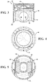
- Figures 1-5 illustrate an exemplary diesel piston 20 formed of steel and including a cooling gallery 24
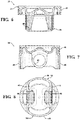
- Figures 6-8 illustrate an exemplary diesel piston 20 formed of steel without a cooling gallery
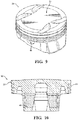
- Figures 9 and 10 illustrate an exemplary gasoline piston 20 formed of aluminum without a cooling gallery.
- another example of the type of piston to which the abradable coating 22 can be applied is a diesel piston formed of aluminum, with or without a cooling gallery.
- the piston 20 includes a body portion 26 formed of a metal material.
- the metal material is typically an iron-based material or an aluminum-based material, but other materials could be used.
- the body portion 26 extends around a center axis A and longitudinally along the center axis A from an upper end 28 to a lower end 30 .
- the piston 20 also includes a crown 32 extending circumferentially about the center axis A from the upper end 28 toward the lower end 30. In the embodiment of Figures 1-5 , the crown 32 is joined to the remainder of the body portion 26, in this case by welding,
- the crown 32 of the piston 20 defines at least one ring groove 36 extending circumferentially about the center axis A for receiving at least one ring (not shown).
- the piston 20 includes two or three ring grooves 36 .
- Ring lands 38 are disposed adjacent each ring groove 36 and space the ring grooves 36 from one another.
- the outer surface 40 of the ring lands 38 can be machined or otherwise formed to a generally "round" shape, which is a shape that is not greater than 0,1 millimeter (mm) from a circular shape.
- the round shape is less costly to machine than an oval shape or another non-round shape, the oval or other non-round shape is typically desired to achieve appropriate contact geometry between the ring lands 38 and cylinder liner of the internal combustion engine.
- the piston 20 can be formed with or without a cooling gallery 24.
- the piston 20 includes the cooling gallery 24 extending circumferentially around the center axis A between the crown 32 and the remainder of the body portion 26.
- the crown 32 includes a pair of upper ribs 42 spaced from the center axis A and from one another
- the adjacent section of the body portion 26 includes a pair of lower ribs 44 spaced from the center axis A and from one another
- the upper ribs 42 are welded to the lower ribs 44 to form the cooling gallery 24.
- the ribs 42, 44 are friction welded together, but the ribs 42, 44 may be joined using other methods.
- the cooling gallery 24 can contain a cooling fluid to dissipate heat away from the hot crown 32 during use of the piston 20 in the internal combustion engine.
- cooling fluid can be sprayed into the cooling gallery 24 or along an interior surface of the crown 32 to reduce the temperature of the crown 24 during use in the internal combustion engine.
- the pistons 20 of Figures 6-10 are formed without a cooling gallery 24.
- the body portion 26 of the piston 20 further includes a pair of pin bosses 46 spaced from one another about the center axis A and depending from the crown 32 to the lower end 30.
- the outer surface 40 along each of the pin bosses 46 faces inwardly and defines a pin bore 48 for receiving a wrist pin 50 which can be used to connect the piston 20 to a connecting rod 52 , as shown in Figure 11 .
- the outer surface 40 of the pin bosses 46 along the pin bore 48 may be machined or otherwise formed to a generally "round" shape, which is a shape that is not greater than 0.1 mm from a circular shape.
- the body portion 26 also includes a pair of skirt sections 54 spacing the pin bosses 46 from one another about the center axis A and depending from the crown 32 to the lower end 30.
- the outer surface 40 of the skirt sections 54 may also be machined or otherwise formed to a generally "round" shape, which is a shape that is not greater than 0.1 mm from a circular shape.
- the skirt sections 54 present the round shape when the piston 20 completes the casting or forging process, without any machining and before any post-casting or post-forging steps.
- the round shape is less costly to create than the oval shape, the oval shape is typically desired to achieve appropriate contact geometry between the skirt sections 54 and cylinder liner of the internal combustion engine.
- the abradable coating 22 is applied along portions of the outer surface 40 of the piston 20 which initially have the round shape in order to obtain a suitable contact geometry, such as the desired oval, asymmetric, or other non-round shape, without the costly machining process.
- the abradable coating 22 can be formed of various different compositions which wear down when rubbed against another component, such as the cylinder liner or wrist pin.
- the abradable coating includes an aluminum-silicon material.
- the abradable coating 22 is formed of a polymer-based material.
- the abradable coating can also include fillers or additives, such as graphite, hexagonal boron nitride, and/or molybdenum disulfide.
- the abradable coating 22 can consist of a polymer and an aluminum-silicon alloy; an aluminum-silicon alloy and graphite; or an aluminum-silicon alloy and hexagonal boron nitride.
- the abradable coating 22 can be applied to any thickness t, but is typically applied to a thickness t ranging from 20 ⁇ m to 400 ⁇ m.
- the abradable coating 22 is applied to the outer surface 40 of the ring lands 38 which presents the round shape, i.e. the shape being not greater than 0.1 mm from a circular shape
- the abradable coating 22 is typically applied to a thickness t of 50 to 300 ⁇ m along the ring lands 38, and the thickness t is typically approximately uniform along the ring lands 38 when initially applied.
- the abradable coating 22 rubs against the cylinder liner as the piston 20 reciprocates along the cylinder liner.
- an exposed surface 56 of the abradable coating 22 wears down to a more suitable shape, for example an oval shape which is greater than 0.1 mm from a circular shape.
- the thickness t of the abradable coating 22 varies along the ring lands 38 after rubbing against the cylinder liner.
- the abradable coating 22 is applied to the outer surface 40 along the pin bores 48 of the pin bosses 46 which face inwardly and present the round shape, i.e. the shape being not greater than 0.1 mm from a circular shape
- the abradable coating 22 is typically applied to a thickness t of 20 to 30 ⁇ m along the pin bores 48 , and the thickness t is typically approximately uniform along the pin bores 48 when initially applied.
- the wrist pin 50 is disposed in the pin bores 48 to connect the piston 20 to the connecting rod 52 , and the abradable coating 22 rubs against the wrist pin 50 as the piston 20 reciprocates along the cylinder liner.
- the exposed surface 56 of the abradable coating 22 wears down to a more suitable shape, such as an oval or asymmetric shape.
- the worn exposed surface 56 along the pin bores 48 could have a shape which is greater than 0,1 mm from a circular shape, or less than 0.1 mm from a circular shape.
- the abradable coating 22 could achieve a trumpet or banana shape after rubbing against the wrist pin 50.
- the thickness t of the abradable coating 22 typically varies along the pin bores 48 after rubbing against the wrist pin 50.
- the abradable coating 22 is also applied to the outer surface 40 of the skirt sections 54 which presents the round shape, i.e. the shape being not greater than 0.1 mm from a circular shape.
- the abradable coating 22 is typically applied to a thickness t of 100 to 400 ⁇ m along the skirt sections 54 , and the thickness t is typically approximately uniform along the skirt sections 54 when initially applied.
- the abradable coating 22 on the skirt sections 54 rubs against the cylinder liner as the piston 20 reciprocates.
- an exposed surface 56 of the abradable coating 22 wears down to a more suitable shape, for example the oval shape which is greater than 0.1 mm from a circular shape.
- the thickness t of the abradable coating 22 varies along the skirt sections 54 after rubbing against the cylinder liner.
- the piston assembly for use in an internal combustion engine.
- the piston assembly also includes the wrist pin 50 and connecting rod 52 , as shown in Figure 11 .
- the connecting rod 52 includes a connecting end 58 with a connecting surface 60 defining a pin opening.
- the pin opening is axially aligned with the pin bores 48 of the piston 20
- the wrist pin 50 extends through the aligned pin opening and pin bores 48 to connect the piston 20 to the connecting rod 52.
- the wrist pin 50 presents a contact surface 62 facing the outer surface 40 of the pin bosses 46 and the connecting surface 60 of the connecting rod 52.
- the abradable coating 22 only needs to be applied to the pin bosses 46 or the wrist pin 50 , not both.
- the abradable coating 22 can also, or alternatively, be applied to the connecting surface 60 of the connecting rod 52 and/or the contact surface 62 of the wrist pin 50.
- Figures 11 and 11a illustrate an exemplary embodiment wherein the abradable coating 22 is applied to the contact surface 62 of the wrist pin 50.
- the abradable coating 22 could alternatively be applied to the connecting surface 60 of the connecting rod 52.
- the abradable coating 22 only needs to be applied to the wrist pin 50 or the connecting rod 52 , not both,
- the contact surface 62 of the wrist pin 50 presents a shape being not greater than 0.1 mm from a circular shape, and the abradable coating 22 is applied to this round contact surface 62.
- the abradable coating 22 is typically applied to a thickness t of 20 to 30 ⁇ m along the contact surface 62 , and the thickness t is typically approximately uniform along the contact surface 62 of the wrist pin 50 when initially applied.
- the abradable coating 22 on the wrist pin 50 rubs against the connecting surface 60 of the connecting rod 52 and the outer surface 40 of the pin bosses 46 as the piston 20 reciprocates along the cylinder liner.
- the exposed surface 56 of the abradable coating 22 wears down to a more suitable shape, such as the oval, asymmetric, or other non-round shape, which could be greater than 0.1 mm from a circular shape.
- the thickness t of the abradable coating 22 typically varies along the wrist pin 50 after rubbing against the connecting rod 52 and piston 20, For example, the abradable coating 22 can achieve a trumpet or banana shape after rubbing against the connecting rod 52 and piston 20 .
- the connecting surface 60 of the connecting rod 52 presents a shape being not greater than 0.1 mm from a circular shape, and the abradable coating 22 is applied to this round contact surface 62 of the connecting rod 52.
- the abradable coating 22 is typically applied to a thickness t of 20 to 30 ⁇ m along the connecting surface 60, and the thickness t is typically approximately uniform along the connecting surface 60 of the connecting rod 52 when initially applied.
- the abradable coating 22 on the connecting rod 52 rubs against the contact surface 62 of the wrist pin 50 as the piston 20 reciprocates along the cylinder liner.
- the exposed surface 56 of the abradable coating 22 wears down to a more suitable shape, such as an oval, asymmetric, or other non-round shape which could be greater than 0.1 mm from a circular shape.
- the thickness t of the abradable coating 22 typically varies along the connecting surface 60 after rubbing against the wrist pin 50.
- the abradable coating 22 along the connecting surface 60 can achieve a trumpet or banana shape after rubbing against the wrist pin 50 .
- Yet another aspect of the invention provides a method of manufacturing the piston 20 with the abradable coating 22 with reduced costs by avoiding deliberate machining of the outer surface 40 to a non-round shape.
- the method generally includes providing the body portion 26 of the piston 20, wherein a portion of the outer surface 40 presents the round shape, i.e. the shape which is not greater than 0.1 mm from a circular shape, and applying the abradable coating 22 to that portion of the outer surface 40 for rubbing against at least one other component of the internal combustion engine.
- the step of providing the body portion 26 of the piston 20 typically includes casting or forging a metal material. Various different designs can be achieved during the casting or forging process. In one embodiment, the portions of the outer surface 40 of the piston 20 to which the abradable coating 22 is applied are formed to a shape which is close to the round shape during the casting or forging process.
- the method further includes machining or otherwise forming the portions of the cast or forged structure to which the abradable coating 22 is applied to achieve the round shape, i.e. the shape which is not greater than 0. 1 mm from a circular shape.
- the body portion 26 of the piston 20 is machined to present a cylindrical shape (constant diameter) or barrel or tapered shape (varying diameter) extending from the upper end 28 to the lower end 30, with the round outer surface 40 along the ring lands 38 and the skirt sections 54.
- the pin bores 48 can also be formed by machining to present a cylindrical or barrel shape with the round outer surface 40. It is noted that machining to the round shape is less costly than machining to oval or asymmetric shapes.
- Other portions of the piston 20 without the abradable coating 22 can also be machined to achieve the desired design.
- the method includes joining those pieces together to form the body portion 26.
- the joining step includes friction welding or induction welding the crown 32 to remaining sections of the body portion 26 .
- the method can optionally include another machining step, for example to machine portions of the piston 20 which will include the abradable coating 22, or portions which will be left uncoated.
- the outer surface 40 of the piston 20 is also cleaned or pre-treated, if required, before applying the abradable coating 22 to the outer surface 40.
- the step of applying the abradable coating 22 to the outer surface 40 of the piston 20 typically includes screen printing, rolling, or spraying, for example thermal spraying.
- the method typically is screen printing, rolling, or spraying.
- the abradable coating 22 includes an aluminum-silicon alloy
- the method typically is thermal spraying,
- the abradable coating 22 can be applied to a thickness t varying from 20 to 400 mm, depending on which portion of the piston 20 is coaled, and the thickness t of the abradable coating 22 is typically approximately uniform when first applied.
- the more suitable contact geometry along the outer surface 40 of the piston 20 is then achieved by using the coated piston 20 in the internal combustion engine.
- the abradable coating 22 rubs against at least one other component of the internal combustion engine such that an exposed surface 56 of the abradable coating 22 presents the more suitable shape which could be greater than 0,1 mm from a circular shape.
- the abradable coating 22 is applied to the ring lands 38 or skirt sections 54, the abradable coating 22 rubs against the cylinder liner and can wear down to an oval shape.
- the abradable coating 22 is applied along the pin bores 48 of the pin bosses 46 , then the abradable coating 22 rubs against the wrist pin 50 and can wear down to an oval or asymmetric shape, The thickness t of the abradable coating 22 is no longer uniform after rubbing against another component in the internal combustion engine,
- the method generally includes providing the piston 20, the connecting rod 52 , and the wrist pin 50 , as described above, and applying the abradable coating 22 to at least one of those components.
- the wrist pin 50 and connecting rod 52 can be prepared for the coating process by cleaning, pretreating, or other known methods.
- the wrist pin 50 and connecting rod 52 can also be machined to achieve the round shape, before applying the abradable coating 22.
- the abradable coating 22 is typically applied to an approximately uniform thickness t ranging from 20 to 30 ⁇ m along the connecting rod 52 or wrist pin 50 by spraying. However, other techniques could be used to apply the abradable coating 22.
- method includes applying the abradable coating 22 to the round outer surface 40 of the piston 20 along the ring lands 38, skirt sections 54, and/or pin bosses 46, as described above, and rubbing the abradable coating 22 against another component to achieve the more suitable shape, which could be greater than 0,1 mm from a circular shape.
- the method includes applying the abradable coating 22 to the contact surface 62 of the wrist pin 50, and rubbing the abradable coating 22 against the outer surface 40 of the pin bosses 46 and connecting surface 60 of the connecting rod 52 so that the abradable coating 22 achieves a suitable shape.
- the method includes applying the abradable coating 22 to at least one of the outer surface 40 of the pin bosses 46 and the connecting surface 60 of the connecting rod 52 , and rubbing the abradable coating 22 against the contact surface 62 of the wrist pin 50 so that the abradable coating 22 presents the a suitable shape, which could be greater than 0.1 mm from a circular shape.
Description
- This invention relates generally to pistons for internal combustion engines, and methods of manufacturing the same.
- Pistons used in internal combustion engines should be designed with appropriate contact geometry for sliding along a cylinder of the internal combustion engine. Oftentimes, an outside running surface, such as the surface of a piston skirt, is machined to an oval shape, in cross-section, to meet such requirements. However, the process of machining the metal material of the piston to the desired oval shape is expensive and requires specialized equipment.
- Wrist pin bores of pistons are also typically formed to an appropriate shape, such as a non-round shape, for accommodating a wrist pin as the piston reciprocates in the cylinder of the engine. This profiled wrist pin bore is also expensive to manufacture, due to the process steps and equipment required to machine the metal material.
- A piston with an abradable coating is known from
US5469777 orUS20110232480 . - One aspect of the invention provides a piston for use in an internal combustion engine capable of achieving appropriate contact geometry without a costly machining step. The piston includes a body portion presenting an outer surface, and a portion of the outer surface presents a shape that is not greater than 0.1 mm from a circular shape. An abradable coating including an aluminum-silicon alloy is applied to that round portion of the outer surface for rubbing against at least one other component of the internal combustion engine and thus achieving the appropriate contact geometry, for example an oval, asymmetric, or other non-circular shape.
- The invention also provides a piston assembly for use in an internal combustion engine. The assembly includes a piston, a connecting rod, and a wrist pin for connecting the piston to the connection rod. The piston includes a body portion presenting an outer surface. The body portion also includes a crown and pair of pin bosses depending from the crown and spaced from one another about a center axis. Each of the pin bosses defines a pin bore. The connecting rod includes a connecting end which is disposed between the pin bosses of the piston. The connecting end has a connecting surface defining a pin opening, and the pin opening is axially aligned with the pin bores of the piston. The wrist pin extends through the aligned pin bores of the piston and pin opening of the connecting rod for connecting the piston to the connecting rod. The wrist pin presents a contact surface facing the pin bosses and the connecting surface of the connecting rod. At least one of the pin bosses of the piston, the connecting surface of the connecting rod, and the contact surface of the wrist pin includes a portion presenting a shape which is not greater than 0.1 mm from a circular shape, and an abradable coating including an aluminum-silicon alloy is applied to that portion of the at least one surface.
- Yet another aspect of the invention provides a method of manufacturing a piston for use in an internal combustion engine. The method includes providing a body portion of a piston presenting an outer surface, wherein a portion of the outer surface presents a shape which is not greater than 0.1 mm from a circular shape. The method further includes applying an abradable coating including an aluminum-silicon alloy to that portion of the outer surface for rubbing against at least one other component of the internal combustion engine.
- Another aspect of the invention provides a method of manufacturing a piston assembly for use in an internal combustion engine, wherein the assembly includes a piston, a connecting rod, and a wrist pin. The method includes providing a body portion of the piston, wherein the body portion presents an outer surface, The body portion also includes a crown, and a pair of pin bosses depending from the crown and spaced from one another about a center axis. Each of the pin bosses defines a pin bore. The method further includes providing the connecting rod with a connecting end for being disposed between the pin bosses of the piston, wherein the connecting end presents a connecting surface defining a pin opening for being axially aligned with the pin bosses of the piston. The method also includes providing the wrist pin for extending through the aligned pin bosses of the piston and pin bore of the connecting rod for connecting the piston to the connecting rod. The wrist pin presents a contact surface for facing the pin bosses and the connecting surface of the connecting rod. The method further includes applying an abradable coating including an aluminum-silicon alloy to at least one of the pin bosses of the piston, the connecting surface of the connecting rod, and the contact surface of the wrist pin including a portion presenting a shape being not greater than 0.1 mm from a circular shape.
- Other advantages of the present invention will be readily appreciated, as the same becomes better understood by reference to the following detailed description when considered in connection with the accompanying drawings wherein:
-
Figure 1 is a side view of a diesel piston formed of steel and including a cooling gallery and an abradable coating, according to an exemplary embodiment; -
Figure 1a is an enlarged view of a portion of the piston ofFigure 1 showing the abradable coating applied to ring lands; -
Figure 1b is an enlarged view of a portion of the piston ofFigure 1 showing the abradable coating applied along a wrist pin bore; -
Figure 1c is an enlarged view of a portion of the piston ofFigure 1 showing the abradable coating applied to a skirt section; -
Figure 2 is a cross-sectional view of the piston ofFigure 1 ; -
Figure 3 is another cross-sectional view of the piston ofFigure 1 ; -
Figure 4 is a top view of the piston ofFigure 1 ; -
Figure 5 is a bottom view of the piston ofFigure 1 ; -
Figure 6 is a cross-sectional view of a diesel piston without a cooling gallery and including the abradable coating, according to an exemplary embodiment; -
Figure 7 is another cross-sectional view of the piston ofFigure 6 ; -
Figure 8 is a bottom view of the piston ofFigure 6 ; -
Figure 9 is a perspective view of a gasoline piston formed of aluminum without a cooling gallery and including the abradable coating, according to an exemplary embodiment; -
Figure 10 is a cross-sectional view of the piston ofFigure 9 ; and -
Figure 11 is a connecting rod and wrist pin that can be coupled to the piston to form a piston assembly, according to an exemplary embodiment; and -
Figure 11a is a cross-sectional view of a portion ofFigure 11 showing the abradable coating applied to the wrist pin. - One aspect of the invention provides a
piston 20 with anabradable coating 22 for an internal combustion engine, as shown in the Figures. During use of thepiston 20 in the internal combustion engine, theabradable coating 22 rubs against another component, such as a cylinder liner or wrist pin, and wears down to a suitable shape. Theabradable coating 22 can be applied to a round running surface of thepiston 20 and then wears down to generate an appropriate contact geometry, for example an oval, asymmetric, or other non-circular shape, during the "running-in phase" of operation. Thus, extensive and costly machining of the piston to achieve the appropriate contact geometry is no longer required. In addition to reducing manufacturing costs by reducing the amount of machining, theabradable coating 22 also has the potential to reduce oil consumption, blow-by, emission output, noise, cylinder liner cavitation, and the number of rings from three to two. - The abradable coating 22can be applied to many types of pistons, for example diesel, gasoline, ethanol, 2-stroke, and 4-stroke pistons, including pistons with or without a cooling gallery.
Figures 1-5 illustrate anexemplary diesel piston 20 formed of steel and including a cooling gallery 24,Figures 6-8 illustrate anexemplary diesel piston 20 formed of steel without a cooling gallery, andFigures 9 and 10 illustrate anexemplary gasoline piston 20 formed of aluminum without a cooling gallery. Although not shown, another example of the type of piston to which theabradable coating 22 can be applied is a diesel piston formed of aluminum, with or without a cooling gallery. - In the exemplary embodiments, the
piston 20 includes abody portion 26 formed of a metal material. The metal material is typically an iron-based material or an aluminum-based material, but other materials could be used. Thebody portion 26 extends around a center axis A and longitudinally along the center axis A from anupper end 28 to alower end 30. Thepiston 20 also includes acrown 32 extending circumferentially about the center axis A from theupper end 28 toward thelower end 30. In the embodiment ofFigures 1-5 , thecrown 32 is joined to the remainder of thebody portion 26, in this case by welding, - The
crown 32 of thepiston 20 defines at least onering groove 36 extending circumferentially about the center axis A for receiving at least one ring (not shown). Typically thepiston 20 includes two or threering grooves 36. Ring lands 38 are disposed adjacent eachring groove 36 and space thering grooves 36 from one another. Theouter surface 40 of the ring lands 38 can be machined or otherwise formed to a generally "round" shape, which is a shape that is not greater than 0,1 millimeter (mm) from a circular shape. Although the round shape is less costly to machine than an oval shape or another non-round shape, the oval or other non-round shape is typically desired to achieve appropriate contact geometry between the ring lands 38 and cylinder liner of the internal combustion engine. - As stated above, the
piston 20 can be formed with or without a cooling gallery 24. In the embodiment ofFigures 1-5 , thepiston 20 includes the cooling gallery 24 extending circumferentially around the center axis A between thecrown 32 and the remainder of thebody portion 26. In this embodiment, thecrown 32 includes a pair ofupper ribs 42 spaced from the center axis A and from one another, the adjacent section of thebody portion 26 includes a pair of lower ribs 44 spaced from the center axis A and from one another, and theupper ribs 42 are welded to the lower ribs 44 to form the cooling gallery 24. In this case, theribs 42, 44 are friction welded together, but theribs 42, 44 may be joined using other methods. The cooling gallery 24 can contain a cooling fluid to dissipate heat away from thehot crown 32 during use of thepiston 20 in the internal combustion engine. In addition, cooling fluid can be sprayed into the cooling gallery 24 or along an interior surface of thecrown 32 to reduce the temperature of the crown 24 during use in the internal combustion engine. Thepistons 20 ofFigures 6-10 are formed without a cooling gallery 24. - The
body portion 26 of thepiston 20 further includes a pair ofpin bosses 46 spaced from one another about the center axis A and depending from thecrown 32 to thelower end 30. Theouter surface 40 along each of thepin bosses 46 faces inwardly and defines a pin bore 48 for receiving a wrist pin 50 which can be used to connect thepiston 20 to a connecting rod 52, as shown inFigure 11 , Theouter surface 40 of thepin bosses 46 along the pin bore 48 may be machined or otherwise formed to a generally "round" shape, which is a shape that is not greater than 0.1 mm from a circular shape. - The
body portion 26 also includes a pair ofskirt sections 54 spacing thepin bosses 46 from one another about the center axis A and depending from thecrown 32 to thelower end 30. Theouter surface 40 of theskirt sections 54 may also be machined or otherwise formed to a generally "round" shape, which is a shape that is not greater than 0.1 mm from a circular shape. In this case, theskirt sections 54 present the round shape when thepiston 20 completes the casting or forging process, without any machining and before any post-casting or post-forging steps. Although the round shape is less costly to create than the oval shape, the oval shape is typically desired to achieve appropriate contact geometry between theskirt sections 54 and cylinder liner of the internal combustion engine. - As alluded to above, the
abradable coating 22 is applied along portions of theouter surface 40 of thepiston 20 which initially have the round shape in order to obtain a suitable contact geometry, such as the desired oval, asymmetric, or other non-round shape, without the costly machining process. Theabradable coating 22 can be formed of various different compositions which wear down when rubbed against another component, such as the cylinder liner or wrist pin. According to the invention the abradable coating includes an aluminum-silicon material. In the exemplary embodiments, theabradable coating 22 is formed of a polymer-based material. The abradable coating can also include fillers or additives, such as graphite, hexagonal boron nitride, and/or molybdenum disulfide. For example, theabradable coating 22 can consist of a polymer and an aluminum-silicon alloy; an aluminum-silicon alloy and graphite; or an aluminum-silicon alloy and hexagonal boron nitride. Theabradable coating 22 can be applied to any thickness t, but is typically applied to a thickness t ranging from 20 µm to 400 µm. - In the exemplary embodiment shown in
Figures 1 and 1a , theabradable coating 22 is applied to theouter surface 40 of the ring lands 38 which presents the round shape, i.e. the shape being not greater than 0.1 mm from a circular shape, Theabradable coating 22 is typically applied to a thickness t of 50 to 300 µm along the ring lands 38, and the thickness t is typically approximately uniform along the ring lands 38 when initially applied. During use of thepiston 20 in the internal combustion engine, theabradable coating 22 rubs against the cylinder liner as thepiston 20 reciprocates along the cylinder liner. Thus, an exposedsurface 56 of theabradable coating 22 wears down to a more suitable shape, for example an oval shape which is greater than 0.1 mm from a circular shape. The thickness t of theabradable coating 22 varies along the ring lands 38 after rubbing against the cylinder liner. - In the exemplary embodiment shown in
Figures 1 and 1b , theabradable coating 22 is applied to theouter surface 40 along the pin bores 48 of thepin bosses 46 which face inwardly and present the round shape, i.e. the shape being not greater than 0.1 mm from a circular shape, Theabradable coating 22 is typically applied to a thickness t of 20 to 30 µm along the pin bores 48, and the thickness t is typically approximately uniform along the pin bores 48 when initially applied. During use of thepiston 20 in the internal combustion engine, the wrist pin 50 is disposed in the pin bores 48 to connect thepiston 20 to the connecting rod 52, and theabradable coating 22 rubs against the wrist pin 50 as thepiston 20 reciprocates along the cylinder liner. Thus, the exposedsurface 56 of theabradable coating 22 wears down to a more suitable shape, such as an oval or asymmetric shape. The worn exposedsurface 56 along the pin bores 48 could have a shape which is greater than 0,1 mm from a circular shape, or less than 0.1 mm from a circular shape. For example, theabradable coating 22 could achieve a trumpet or banana shape after rubbing against the wrist pin 50. The thickness t of theabradable coating 22 typically varies along the pin bores 48 after rubbing against the wrist pin 50. - In the exemplary embodiment shown in
Figures 1 and 1c , theabradable coating 22 is also applied to theouter surface 40 of theskirt sections 54 which presents the round shape, i.e. the shape being not greater than 0.1 mm from a circular shape. Theabradable coating 22 is typically applied to a thickness t of 100 to 400 µm along theskirt sections 54, and the thickness t is typically approximately uniform along theskirt sections 54 when initially applied. During use of thepiston 20 in the internal combustion engine, theabradable coating 22 on theskirt sections 54 rubs against the cylinder liner as thepiston 20 reciprocates. Thus, an exposedsurface 56 of theabradable coating 22 wears down to a more suitable shape, for example the oval shape which is greater than 0.1 mm from a circular shape. The thickness t of theabradable coating 22 varies along theskirt sections 54 after rubbing against the cylinder liner. - Another aspect of the invention provides a piston assembly for use in an internal combustion engine. In addition to the
body portion 26, as described above, the piston assembly also includes the wrist pin 50 and connecting rod 52, as shown inFigure 11 . The connecting rod 52 includes a connecting end 58 with a connecting surface 60 defining a pin opening. During use of the piston assembly in the internal combustion engine, the pin opening is axially aligned with the pin bores 48 of thepiston 20, and the wrist pin 50 extends through the aligned pin opening and pin bores 48 to connect thepiston 20 to the connecting rod 52. The wrist pin 50 presents a contact surface 62 facing theouter surface 40 of thepin bosses 46 and the connecting surface 60 of the connecting rod 52. Theabradable coating 22 only needs to be applied to thepin bosses 46 or the wrist pin 50, not both. - In addition to applying the
abradable coating 22 to portions of thepiston 20, as described above, theabradable coating 22 can also, or alternatively, be applied to the connecting surface 60 of the connecting rod 52 and/or the contact surface 62 of the wrist pin 50.Figures 11 and 11a illustrate an exemplary embodiment wherein theabradable coating 22 is applied to the contact surface 62 of the wrist pin 50. However, theabradable coating 22 could alternatively be applied to the connecting surface 60 of the connecting rod 52. Theabradable coating 22 only needs to be applied to the wrist pin 50 or the connecting rod 52, not both, - In the embodiment of
Figures 11 and 11a , the contact surface 62 of the wrist pin 50 presents a shape being not greater than 0.1 mm from a circular shape, and theabradable coating 22 is applied to this round contact surface 62. Theabradable coating 22 is typically applied to a thickness t of 20 to 30 µm along the contact surface 62, and the thickness t is typically approximately uniform along the contact surface 62 of the wrist pin 50 when initially applied. During use of thepiston 20 in the internal combustion engine, theabradable coating 22 on the wrist pin 50 rubs against the connecting surface 60 of the connecting rod 52 and theouter surface 40 of thepin bosses 46 as thepiston 20 reciprocates along the cylinder liner. Thus, the exposedsurface 56 of theabradable coating 22 wears down to a more suitable shape, such as the oval, asymmetric, or other non-round shape, which could be greater than 0.1 mm from a circular shape. The thickness t of theabradable coating 22 typically varies along the wrist pin 50 after rubbing against the connecting rod 52 andpiston 20, For example, theabradable coating 22 can achieve a trumpet or banana shape after rubbing against the connecting rod 52 andpiston 20. - In another embodiment, the connecting surface 60 of the connecting rod 52 presents a shape being not greater than 0.1 mm from a circular shape, and the
abradable coating 22 is applied to this round contact surface 62 of the connecting rod 52. Theabradable coating 22 is typically applied to a thickness t of 20 to 30 µm along the connecting surface 60, and the thickness t is typically approximately uniform along the connecting surface 60 of the connecting rod 52 when initially applied. During use of thepiston 20 in the internal combustion engine, theabradable coating 22 on the connecting rod 52 rubs against the contact surface 62 of the wrist pin 50 as thepiston 20 reciprocates along the cylinder liner. Thus, the exposedsurface 56 of theabradable coating 22 wears down to a more suitable shape, such as an oval, asymmetric, or other non-round shape which could be greater than 0.1 mm from a circular shape. The thickness t of theabradable coating 22 typically varies along the connecting surface 60 after rubbing against the wrist pin 50. For example, theabradable coating 22 along the connecting surface 60 can achieve a trumpet or banana shape after rubbing against the wrist pin 50. - Yet another aspect of the invention provides a method of manufacturing the
piston 20 with theabradable coating 22 with reduced costs by avoiding deliberate machining of theouter surface 40 to a non-round shape. The method generally includes providing thebody portion 26 of thepiston 20, wherein a portion of theouter surface 40 presents the round shape, i.e. the shape which is not greater than 0.1 mm from a circular shape, and applying theabradable coating 22 to that portion of theouter surface 40 for rubbing against at least one other component of the internal combustion engine. - The step of providing the
body portion 26 of thepiston 20 typically includes casting or forging a metal material. Various different designs can be achieved during the casting or forging process. In one embodiment, the portions of theouter surface 40 of thepiston 20 to which theabradable coating 22 is applied are formed to a shape which is close to the round shape during the casting or forging process. - The method further includes machining or otherwise forming the portions of the cast or forged structure to which the
abradable coating 22 is applied to achieve the round shape, i.e. the shape which is not greater than 0. 1 mm from a circular shape. In one embodiment, thebody portion 26 of thepiston 20 is machined to present a cylindrical shape (constant diameter) or barrel or tapered shape (varying diameter) extending from theupper end 28 to thelower end 30, with the roundouter surface 40 along the ring lands 38 and theskirt sections 54. The pin bores 48 can also be formed by machining to present a cylindrical or barrel shape with the roundouter surface 40. It is noted that machining to the round shape is less costly than machining to oval or asymmetric shapes. Other portions of thepiston 20 without theabradable coating 22 can also be machined to achieve the desired design. - In cases where the
piston 20 includes multiple pieces, for example thepiston 20 with theseparate crown 32 shown inFigure 1 , the method includes joining those pieces together to form thebody portion 26. In one embodiment, the joining step includes friction welding or induction welding thecrown 32 to remaining sections of thebody portion 26. - Once the
body portion 26 is formed, the method can optionally include another machining step, for example to machine portions of thepiston 20 which will include theabradable coating 22, or portions which will be left uncoated. Theouter surface 40 of thepiston 20 is also cleaned or pre-treated, if required, before applying theabradable coating 22 to theouter surface 40. - The step of applying the
abradable coating 22 to theouter surface 40 of thepiston 20 typically includes screen printing, rolling, or spraying, for example thermal spraying. However, other processes can be used to apply theabradable coating 22. When theabradable coating 22 includes a polymer and graphite, the method typically is screen printing, rolling, or spraying. When theabradable coating 22 includes an aluminum-silicon alloy, the method typically is thermal spraying, Theabradable coating 22 can be applied to a thickness t varying from 20 to 400 mm, depending on which portion of thepiston 20 is coaled, and the thickness t of theabradable coating 22 is typically approximately uniform when first applied. - The more suitable contact geometry along the
outer surface 40 of thepiston 20 is then achieved by using the coatedpiston 20 in the internal combustion engine. As described above, as thepiston 20 reciprocates along the cylinder liner, theabradable coating 22 rubs against at least one other component of the internal combustion engine such that an exposedsurface 56 of theabradable coating 22 presents the more suitable shape which could be greater than 0,1 mm from a circular shape. For example, if theabradable coating 22 is applied to the ring lands 38 orskirt sections 54, theabradable coating 22 rubs against the cylinder liner and can wear down to an oval shape. If theabradable coating 22 is applied along the pin bores 48 of thepin bosses 46, then theabradable coating 22 rubs against the wrist pin 50 and can wear down to an oval or asymmetric shape, The thickness t of theabradable coating 22 is no longer uniform after rubbing against another component in the internal combustion engine, - Another aspect of the invention provides a method of manufacturing the piston assembly for use in the internal combustion engine. The method generally includes providing the
piston 20, the connecting rod 52, and the wrist pin 50, as described above, and applying theabradable coating 22 to at least one of those components. The wrist pin 50 and connecting rod 52 can be prepared for the coating process by cleaning, pretreating, or other known methods. The wrist pin 50 and connecting rod 52 can also be machined to achieve the round shape, before applying theabradable coating 22. Theabradable coating 22 is typically applied to an approximately uniform thickness t ranging from 20 to 30 µm along the connecting rod 52 or wrist pin 50 by spraying. However, other techniques could be used to apply theabradable coating 22. - In one embodiment, method includes applying the
abradable coating 22 to the roundouter surface 40 of thepiston 20 along the ring lands 38,skirt sections 54, and/orpin bosses 46, as described above, and rubbing theabradable coating 22 against another component to achieve the more suitable shape, which could be greater than 0,1 mm from a circular shape. In another embodiment, the method includes applying theabradable coating 22 to the contact surface 62 of the wrist pin 50, and rubbing theabradable coating 22 against theouter surface 40 of thepin bosses 46 and connecting surface 60 of the connecting rod 52 so that theabradable coating 22 achieves a suitable shape. In yet another embodiment, the method includes applying theabradable coating 22 to at least one of theouter surface 40 of thepin bosses 46 and the connecting surface 60 of the connecting rod 52, and rubbing theabradable coating 22 against the contact surface 62 of the wrist pin 50 so that theabradable coating 22 presents the a suitable shape, which could be greater than 0.1 mm from a circular shape. - Obviously, many modifications and variations of the present invention are possible in light of the above teachings and may be practiced otherwise than as specifically described while within the scope of the appended claims.
Claims (15)
- A piston (20) for use in an internal combustion engine, comprising:a body portion (26) presenting an outer surface (40), a portion of said outer surface (40) presenting a shape being not greater than 0.1 mm from a circular shape; andan abradable coating (22) applied to said portion of said outer surface (40) for rubbing against at least one other component of the internal combustion engine,and wherein said body portion (26) of said piston (20) includes a crown (32) having at least one ring groove (36) extending about a center axis and ring lands (38) each disposed adjacent one of said ring grooves (36), and said abradable coating (22) is applied to said outer surface (40) along said ring lands (38), and/orwherein said body portion (26) includes a crown (32), said body portion (26) includes a pair of skirt sections (54) spacing a pair of pin bosses (46) from one another about a center axis and depending from said crown (32), and said abradable coating (22) is applied to said outer surface (40) along said skirt sections (54), characterized in that said abradable coating (22) includes an aluminum-silicon alloy.
- The piston (20) of claim 1, wherein said body portion (26) includes a crown (32), said body portion (26) includes a pair of pin bosses (46) depending from said crown (32) and spaced from one another about a center axis, each of said pin bosses (46) defines a pin bore for receiving a wrist pin (50), and said abradable coating (22) is applied to said outer surface (40) along said pin bore of said pin bosses (46).
- The piston (20) of claim 1, wherein said abradable coating (22) includes at least one of: a polymer, graphite, and hexagonal boron nitride.
- The piston (20) of claim 1, wherein said abradable coating (22) has a thickness of 20 to 400 µm.
- The piston (20) of claim 1, wherein an exposed surface of said abradable coating (22) presents a shape being greater than 0.1 mm from a circular shape after said abradable coating (22) rubs against the at least one other component of the internal combustion engine.
- The piston (20) of claim 1, wherein said body portion (26) is formed of a metal material, said metal material being selected from an iron-based material and an aluminum-based material;said body portion (26) extends around a center axis and longitudinally along said center axis from an upper end (28) to a lower end (30);said body portion (26) includes a crown (32) extending circumferentially about said center axis from said upper end (28) toward said lower end (30);said crown (32) defines at least one ring groove (36) extending circumferentially about said center axis for receiving at least one ring;a plurality of ring lands (38) each disposed adjacent one of said ring grooves (36);said outer surface (40) of said ring lands (38) presenting said shape being not greater than 0.1 mm from a circular shape;said abradable coating (22) applied to said outer surface (40) of said ring lands (38);said abradable coating (22) having a thickness of 50 to 300 µm along said ring lands (38);
said abradable coating (22) including at least one of: a polymer, an aluminum-silicon alloy, graphite, and hexagonal boron nitride;
said body portion (26) including a pair of pin bosses (46) spaced from one another about said center axis and depending from said crown (32) to said lower end (30);
each of said pin bosses (46) defining a pin bore for receiving a wrist pin (50);
said outer surface (40) along each of said pin bosses (46) defining said pin bore, and said pin bore presenting said shape being not greater than 0.1 mm from a circular shape;
said abradable coating (22) being applied to said outer surface (40) along said pin bores of said pin bosses (46);
said abradable coating (22) having a thickness of 20 to 30 µm along said pin bores;
said body portion (26) including a pair of skirt sections (54) spacing said pin bosses (46) from one another about said center axis and depending from said lower crown (32) to said lower end (30);
said outer surface (40) of said skirt sections (54) presenting said shape being not greater than 0.1 mm from a circular shape;
an abradable coating (22) applied to said outer surface (40) of said skirt sections (54); and
said abradable coating (22) having a thickness of 100 to 400 µm along said skirt sections (54). - A piston assembly for use in an internal combustion engine, comprising:a piston (20) including a body portion (26) presenting an outer surface (40),
said body portion (26) including a crown (32) and a pair of pin bosses (46) depending from said crown (32) and spaced from one another about a center axis, each of said pin bosses (46) defines a pin bore;a connecting rod (52) including a connecting end (58) disposed between said pin bosses (46) of said piston (20);said connecting end (58) presenting a connecting surface (60) defining a pin opening, said pin opening being axially aligned with said pin bores of said piston (20);a wrist pin (50) extending through said aligned pin bores of said piston (20) and pin opening of said connecting rod (52) for connecting said piston (20) to said connecting rod (52), said wrist pin (50) presenting a contact surface facing said outer surface (40) of said pin bosses (46) and said connecting surface (60) of said connecting rod (52);at least one of said outer surface (40) of said piston (20), said connecting surface (60) of said connecting rod (52), and said contact surface of said wrist pin (50) including a portion presenting a shape being not greater than 0.1 mm from a circular shape; and
an abradable coating (22) applied to said portion of said at least one surface,
characterized in that said abradable coating (22) includes an aluminum-silicon alloy. - The piston assembly of claim 7, wherein said abradable coating (22) is applied to said contact surface of said wrist pin (50).
- The piston assembly of claim 7, wherein said abradable coating (22) is applied to at least one of said outer surface (40) of said pin bosses (46) and said connecting surface (60) of said connecting rod (52).
- A method of manufacturing a piston (20) for use in an internal combustion engine, comprising the steps of:
providing a body portion (26) of a piston (20) presenting an outer surface (40), a portion of the outer surface (40) presenting a shape being not greater than 0.1 mm from a circular shape; and
applying an abradable coating (22) to the portion of the outer surface (40) for rubbing against at least one other component of the internal combustion engine, chraracterized in that said abradable coating (22) includes an aluminum-silicon alloy. - The method of claim 10, wherein the step of applying the abradable coating (22) includes at least one of: screen printing, rolling, and spraying the abradable coating (22) onto the portion of the outer surface (40).
- The method of claim 11, wherein the step of applying the abradable coating (22) includes thermal spraying the abradable coating (22) onto the portion of the outer surface (40).
- The method of claim 10, wherein the step of providing the body portion (26) of the piston (20) includes machining the portion of the outer surface (40) to the shape being not greater than 0.1 mm from a circular shape.
- A method of manufacturing a piston assembly for use in an internal combustion engine, comprising the steps of:providing a body portion (26) of a piston (20), the body portion (26) presenting an outer surface (40), the body portion (26) including a crown (32) and a pair of pin bosses (46) depending from the crown (32) and spaced from one another about a center axis, and each of the pin bosses (46) defining a pin bore;providing a connecting rod (52) for being disposed between the pin bosses (46) of the piston (20), the connecting rod (52) including a connecting end (58) with a connecting surface (60) defining a pin opening for being axially aligned with the pin bosses (46) of the piston (20);providing a wrist pin (50) for extending through the aligned pin bosses (46) of the piston (20) and pin bore of the connecting rod (52) for connecting the piston (20) to the connecting rod (52), the wrist pin (50) presenting a contact surface for facing the outer surface (40) of the pin bosses (46) and the connecting surface (60) of the connecting rod (52); andapplying an abradable coating (22) to at least one of the outer surface (40) of the piston (20), the connecting surface (60) of the connecting rod (52), and the contact surface of the wrist pin (50) including a portion presenting a shape being not greater than 0.1 mm from a circular shape,characterized in that said abradable coating (22) includes an aluminum-silicon alloy.
- The method of claim 14, wherein the step of applying the abradable coating (22) includes at least one of screen printing, rolling, and spraying the abradable coating (22) onto the portion of the outer surface (40).
Applications Claiming Priority (2)
| Application Number | Priority Date | Filing Date | Title |
|---|---|---|---|
| US201461935518P | 2014-02-04 | 2014-02-04 | |
| PCT/US2015/014409 WO2015120016A1 (en) | 2014-02-04 | 2015-02-04 | Piston with abradable coating to generate appropriate contact geometry on running surface |
Publications (2)
| Publication Number | Publication Date |
|---|---|
| EP3105434A1 EP3105434A1 (en) | 2016-12-21 |
| EP3105434B1 true EP3105434B1 (en) | 2020-04-29 |
Family
ID=53754449
Family Applications (1)
| Application Number | Title | Priority Date | Filing Date |
|---|---|---|---|
| EP15704910.7A Active EP3105434B1 (en) | 2014-02-04 | 2015-02-04 | Piston with abradable coating to generate appropriate contact geometry on running surface |
Country Status (3)
| Country | Link |
|---|---|
| US (1) | US9909528B2 (en) |
| EP (1) | EP3105434B1 (en) |
| WO (1) | WO2015120016A1 (en) |
Families Citing this family (5)
| Publication number | Priority date | Publication date | Assignee | Title |
|---|---|---|---|---|
| US9903310B2 (en) * | 2016-05-05 | 2018-02-27 | Mahle International Gmbh | Piston with anti-carbon coating and method for applying an anti-carbon coating on a piston |
| CN106435673A (en) * | 2016-12-22 | 2017-02-22 | 日照金港活塞有限公司 | Preparation technology of thermal insulation coating on internal combustion engine forging steel piston top |
| US10926330B2 (en) | 2017-02-17 | 2021-02-23 | Tenneco Inc. | Steel piston with metallurgically bonded bushing and method of manufacturing |
| WO2020234856A1 (en) * | 2019-05-22 | 2020-11-26 | Viveknath Richards | Piston design with specialized geometry for internal combustion engine |
| JP7435865B1 (en) | 2023-03-09 | 2024-02-21 | いすゞ自動車株式会社 | engine structure |
Citations (2)
| Publication number | Priority date | Publication date | Assignee | Title |
|---|---|---|---|---|
| JPH1046361A (en) * | 1996-08-02 | 1998-02-17 | Toyota Motor Corp | Aluminum alloy sliding member, its production and piston |
| CN201280980Y (en) * | 2008-10-31 | 2009-07-29 | 山东振挺精工活塞有限公司 | Aluminium-silicon alloy piston with thermal insulating layer on surface |
Family Cites Families (23)
| Publication number | Priority date | Publication date | Assignee | Title |
|---|---|---|---|---|
| FR2076799A5 (en) | 1970-01-28 | 1971-10-15 | Negre Guy | |
| JPS59190455A (en) * | 1983-04-11 | 1984-10-29 | Mazda Motor Corp | Method of settling shape of piston for internal- combustion engine |
| DE3418454A1 (en) * | 1984-05-18 | 1985-12-19 | Kolbenschmidt AG, 7107 Neckarsulm | LIGHT METAL PISTON |
| DE3527032A1 (en) * | 1985-07-27 | 1987-01-29 | Mahle Gmbh | SUBMERSIBLE PISTON, IN PARTICULAR FOR COMBUSTION ENGINES |
| US5172626A (en) | 1991-08-22 | 1992-12-22 | General Motors Corporation | Stabilized piston skirt having varying peaks and concave surfaces |
| DE4133546C2 (en) | 1991-10-10 | 2000-12-07 | Mahle Gmbh | Piston-cylinder arrangement of an internal combustion engine |
| US5435873A (en) | 1991-11-01 | 1995-07-25 | Decc Technology Partnership, A Limited Partnership Of Which The Decc Company, Inc. Is A General Partner | Method and apparatus for sizing a piston |
| US5266142A (en) | 1991-11-01 | 1993-11-30 | Decc Technology Partnership A Limited Partnership | Coated piston and method and apparatus of coating the same |
| US5435872A (en) | 1991-11-01 | 1995-07-25 | Decc Technology Partnership | Sized coated pistons |
| US5261321A (en) * | 1992-03-06 | 1993-11-16 | Zollner Corporation | Piston having oval shaped crown |
| DE4240050A1 (en) | 1992-11-28 | 1994-06-01 | Mahle Gmbh | Piston-cylinder device of an internal combustion engine |
| US5239955A (en) * | 1993-01-07 | 1993-08-31 | Ford Motor Company | Low friction reciprocating piston assembly |
| US5469777A (en) | 1994-07-05 | 1995-11-28 | Ford Motor Company | Piston assembly having abradable coating |
| US5477820A (en) | 1994-09-29 | 1995-12-26 | Ford Motor Company | Thermal management system for heat engine components |
| DE29801168U1 (en) | 1998-01-24 | 1999-08-12 | Medico Dev Investment Co | Injection device |
| US5884600A (en) | 1998-02-20 | 1999-03-23 | General Motors Corporation | Aluminum bore engine having wear and scuff-resistant aluminum piston |
| JP4379852B2 (en) | 2001-06-27 | 2009-12-09 | 本田技研工業株式会社 | Piston for internal combustion engine made of aluminum alloy |
| DE102005061063A1 (en) | 2005-12-21 | 2007-06-28 | Mahle International Gmbh | Piston for internal combustion engine has hub borings in form of borings of circular internal outline with resin coating containing solid lubricant particles |
| WO2008088600A1 (en) | 2006-10-30 | 2008-07-24 | Suman Andrew W | Abradable dry film lubricant and the method for applying same and article made therefrom |
| US7536945B2 (en) * | 2006-12-29 | 2009-05-26 | Mahle Technology, Inc. | Piston pin for a combustion engine and method for its manufacture |
| US20080163751A1 (en) | 2007-01-09 | 2008-07-10 | Vijay Subramanian | Coated piston and coating method |
| US8408116B2 (en) * | 2009-04-01 | 2013-04-02 | Delaware Capital Formation, Inc. | Method of fitting a piston for use in an internal combustion engine |
| JP5885531B2 (en) | 2012-02-16 | 2016-03-15 | 日立オートモティブシステムズ株式会社 | Piston of internal combustion engine |
-
2015
- 2015-02-04 WO PCT/US2015/014409 patent/WO2015120016A1/en active Application Filing
- 2015-02-04 EP EP15704910.7A patent/EP3105434B1/en active Active
- 2015-02-04 US US14/613,603 patent/US9909528B2/en not_active Expired - Fee Related
Patent Citations (2)
| Publication number | Priority date | Publication date | Assignee | Title |
|---|---|---|---|---|
| JPH1046361A (en) * | 1996-08-02 | 1998-02-17 | Toyota Motor Corp | Aluminum alloy sliding member, its production and piston |
| CN201280980Y (en) * | 2008-10-31 | 2009-07-29 | 山东振挺精工活塞有限公司 | Aluminium-silicon alloy piston with thermal insulating layer on surface |
Also Published As
| Publication number | Publication date |
|---|---|
| US20150219042A1 (en) | 2015-08-06 |
| WO2015120016A1 (en) | 2015-08-13 |
| EP3105434A1 (en) | 2016-12-21 |
| US9909528B2 (en) | 2018-03-06 |
Similar Documents
| Publication | Publication Date | Title |
|---|---|---|
| EP3105434B1 (en) | Piston with abradable coating to generate appropriate contact geometry on running surface | |
| JP6231781B2 (en) | Different thickness coatings for cylinder liners | |
| US20130025561A1 (en) | Bowl rim and root protection for aluminum pistons | |
| US10359000B2 (en) | Functionally optimized design of a cylinder liner | |
| US10926330B2 (en) | Steel piston with metallurgically bonded bushing and method of manufacturing | |
| EP3146188B1 (en) | Piston with keystone second ring groove for high temperature internal combustion engines | |
| US10655561B2 (en) | Cast light metal piston | |
| US8857401B2 (en) | Low drag piston | |
| JP6455870B2 (en) | Workpiece with cutout for receiving piston | |
| US10428945B2 (en) | Inlaid ring with plated lateral side | |
| US9291192B2 (en) | Connecting rod with bearing-less large end | |
| EP2964939B1 (en) | Piston with anti-carbon deposit coating and method of construction thereof | |
| US9551291B2 (en) | Steel piston with fourth land guidance and improved friction characteristics | |
| US9599148B2 (en) | Thermal spray coating for connecting rod small end | |
| US10731598B2 (en) | Piston having an undercrown surface with coating and method of manufacture thereof | |
| KR102364805B1 (en) | Reinforcement of the piston ring-belt structure through additional machining | |
| US20220065188A1 (en) | Internal combustion engine including an element at the cylinder inner wall for scraping off oil carbon | |
| US20160252042A1 (en) | Cylinder Liner | |
| EP4314600A1 (en) | Coated piston ring for an internal combustion engine | |
| WO2021050471A1 (en) | Coated piston ring for an internal combustion engine | |
| MAHLE GmbH | Piston design guidelines | |
| JPS595863A (en) | Piston |
Legal Events
| Date | Code | Title | Description |
|---|---|---|---|
| STAA | Information on the status of an ep patent application or granted ep patent |
Free format text: STATUS: THE INTERNATIONAL PUBLICATION HAS BEEN MADE |
|
| PUAI | Public reference made under article 153(3) epc to a published international application that has entered the european phase |
Free format text: ORIGINAL CODE: 0009012 |
|
| STAA | Information on the status of an ep patent application or granted ep patent |
Free format text: STATUS: REQUEST FOR EXAMINATION WAS MADE |
|
| 17P | Request for examination filed |
Effective date: 20160819 |
|
| AK | Designated contracting states |
Kind code of ref document: A1 Designated state(s): AL AT BE BG CH CY CZ DE DK EE ES FI FR GB GR HR HU IE IS IT LI LT LU LV MC MK MT NL NO PL PT RO RS SE SI SK SM TR |
|
| AX | Request for extension of the european patent |
Extension state: BA ME |
|
| DAX | Request for extension of the european patent (deleted) | ||
| RAP1 | Party data changed (applicant data changed or rights of an application transferred) |
Owner name: FEDERAL-MOGUL LLC |
|
| GRAP | Despatch of communication of intention to grant a patent |
Free format text: ORIGINAL CODE: EPIDOSNIGR1 |
|
| STAA | Information on the status of an ep patent application or granted ep patent |
Free format text: STATUS: GRANT OF PATENT IS INTENDED |
|
| INTG | Intention to grant announced |
Effective date: 20191128 |
|
| GRAS | Grant fee paid |
Free format text: ORIGINAL CODE: EPIDOSNIGR3 |
|
| GRAA | (expected) grant |
Free format text: ORIGINAL CODE: 0009210 |
|
| STAA | Information on the status of an ep patent application or granted ep patent |
Free format text: STATUS: THE PATENT HAS BEEN GRANTED |
|
| RAP1 | Party data changed (applicant data changed or rights of an application transferred) |
Owner name: TENNECO INC. |
|
| AK | Designated contracting states |
Kind code of ref document: B1 Designated state(s): AL AT BE BG CH CY CZ DE DK EE ES FI FR GB GR HR HU IE IS IT LI LT LU LV MC MK MT NL NO PL PT RO RS SE SI SK SM TR |
|
| REG | Reference to a national code |
Ref country code: GB Ref legal event code: FG4D |
|
| REG | Reference to a national code |
Ref country code: CH Ref legal event code: EP |
|
| REG | Reference to a national code |
Ref country code: AT Ref legal event code: REF Ref document number: 1263665 Country of ref document: AT Kind code of ref document: T Effective date: 20200515 |
|
| REG | Reference to a national code |
Ref country code: DE Ref legal event code: R096 Ref document number: 602015051562 Country of ref document: DE |
|
| REG | Reference to a national code |
Ref country code: IE Ref legal event code: FG4D |
|
| REG | Reference to a national code |
Ref country code: NL Ref legal event code: MP Effective date: 20200429 |
|
| REG | Reference to a national code |
Ref country code: LT Ref legal event code: MG4D |
|
| PG25 | Lapsed in a contracting state [announced via postgrant information from national office to epo] |
Ref country code: LT Free format text: LAPSE BECAUSE OF FAILURE TO SUBMIT A TRANSLATION OF THE DESCRIPTION OR TO PAY THE FEE WITHIN THE PRESCRIBED TIME-LIMIT Effective date: 20200429 Ref country code: NO Free format text: LAPSE BECAUSE OF FAILURE TO SUBMIT A TRANSLATION OF THE DESCRIPTION OR TO PAY THE FEE WITHIN THE PRESCRIBED TIME-LIMIT Effective date: 20200729 Ref country code: FI Free format text: LAPSE BECAUSE OF FAILURE TO SUBMIT A TRANSLATION OF THE DESCRIPTION OR TO PAY THE FEE WITHIN THE PRESCRIBED TIME-LIMIT Effective date: 20200429 Ref country code: IS Free format text: LAPSE BECAUSE OF FAILURE TO SUBMIT A TRANSLATION OF THE DESCRIPTION OR TO PAY THE FEE WITHIN THE PRESCRIBED TIME-LIMIT Effective date: 20200829 Ref country code: SE Free format text: LAPSE BECAUSE OF FAILURE TO SUBMIT A TRANSLATION OF THE DESCRIPTION OR TO PAY THE FEE WITHIN THE PRESCRIBED TIME-LIMIT Effective date: 20200429 Ref country code: PT Free format text: LAPSE BECAUSE OF FAILURE TO SUBMIT A TRANSLATION OF THE DESCRIPTION OR TO PAY THE FEE WITHIN THE PRESCRIBED TIME-LIMIT Effective date: 20200831 Ref country code: GR Free format text: LAPSE BECAUSE OF FAILURE TO SUBMIT A TRANSLATION OF THE DESCRIPTION OR TO PAY THE FEE WITHIN THE PRESCRIBED TIME-LIMIT Effective date: 20200730 |
|
| REG | Reference to a national code |
Ref country code: AT Ref legal event code: MK05 Ref document number: 1263665 Country of ref document: AT Kind code of ref document: T Effective date: 20200429 |
|
| PG25 | Lapsed in a contracting state [announced via postgrant information from national office to epo] |
Ref country code: BG Free format text: LAPSE BECAUSE OF FAILURE TO SUBMIT A TRANSLATION OF THE DESCRIPTION OR TO PAY THE FEE WITHIN THE PRESCRIBED TIME-LIMIT Effective date: 20200729 Ref country code: HR Free format text: LAPSE BECAUSE OF FAILURE TO SUBMIT A TRANSLATION OF THE DESCRIPTION OR TO PAY THE FEE WITHIN THE PRESCRIBED TIME-LIMIT Effective date: 20200429 Ref country code: LV Free format text: LAPSE BECAUSE OF FAILURE TO SUBMIT A TRANSLATION OF THE DESCRIPTION OR TO PAY THE FEE WITHIN THE PRESCRIBED TIME-LIMIT Effective date: 20200429 Ref country code: RS Free format text: LAPSE BECAUSE OF FAILURE TO SUBMIT A TRANSLATION OF THE DESCRIPTION OR TO PAY THE FEE WITHIN THE PRESCRIBED TIME-LIMIT Effective date: 20200429 |
|
| PG25 | Lapsed in a contracting state [announced via postgrant information from national office to epo] |
Ref country code: AL Free format text: LAPSE BECAUSE OF FAILURE TO SUBMIT A TRANSLATION OF THE DESCRIPTION OR TO PAY THE FEE WITHIN THE PRESCRIBED TIME-LIMIT Effective date: 20200429 Ref country code: NL Free format text: LAPSE BECAUSE OF FAILURE TO SUBMIT A TRANSLATION OF THE DESCRIPTION OR TO PAY THE FEE WITHIN THE PRESCRIBED TIME-LIMIT Effective date: 20200429 |
|
| PG25 | Lapsed in a contracting state [announced via postgrant information from national office to epo] |
Ref country code: CZ Free format text: LAPSE BECAUSE OF FAILURE TO SUBMIT A TRANSLATION OF THE DESCRIPTION OR TO PAY THE FEE WITHIN THE PRESCRIBED TIME-LIMIT Effective date: 20200429 Ref country code: RO Free format text: LAPSE BECAUSE OF FAILURE TO SUBMIT A TRANSLATION OF THE DESCRIPTION OR TO PAY THE FEE WITHIN THE PRESCRIBED TIME-LIMIT Effective date: 20200429 Ref country code: AT Free format text: LAPSE BECAUSE OF FAILURE TO SUBMIT A TRANSLATION OF THE DESCRIPTION OR TO PAY THE FEE WITHIN THE PRESCRIBED TIME-LIMIT Effective date: 20200429 Ref country code: ES Free format text: LAPSE BECAUSE OF FAILURE TO SUBMIT A TRANSLATION OF THE DESCRIPTION OR TO PAY THE FEE WITHIN THE PRESCRIBED TIME-LIMIT Effective date: 20200429 Ref country code: DK Free format text: LAPSE BECAUSE OF FAILURE TO SUBMIT A TRANSLATION OF THE DESCRIPTION OR TO PAY THE FEE WITHIN THE PRESCRIBED TIME-LIMIT Effective date: 20200429 Ref country code: EE Free format text: LAPSE BECAUSE OF FAILURE TO SUBMIT A TRANSLATION OF THE DESCRIPTION OR TO PAY THE FEE WITHIN THE PRESCRIBED TIME-LIMIT Effective date: 20200429 Ref country code: IT Free format text: LAPSE BECAUSE OF FAILURE TO SUBMIT A TRANSLATION OF THE DESCRIPTION OR TO PAY THE FEE WITHIN THE PRESCRIBED TIME-LIMIT Effective date: 20200429 Ref country code: SM Free format text: LAPSE BECAUSE OF FAILURE TO SUBMIT A TRANSLATION OF THE DESCRIPTION OR TO PAY THE FEE WITHIN THE PRESCRIBED TIME-LIMIT Effective date: 20200429 |
|
| REG | Reference to a national code |
Ref country code: DE Ref legal event code: R097 Ref document number: 602015051562 Country of ref document: DE |
|
| PG25 | Lapsed in a contracting state [announced via postgrant information from national office to epo] |
Ref country code: PL Free format text: LAPSE BECAUSE OF FAILURE TO SUBMIT A TRANSLATION OF THE DESCRIPTION OR TO PAY THE FEE WITHIN THE PRESCRIBED TIME-LIMIT Effective date: 20200429 Ref country code: SK Free format text: LAPSE BECAUSE OF FAILURE TO SUBMIT A TRANSLATION OF THE DESCRIPTION OR TO PAY THE FEE WITHIN THE PRESCRIBED TIME-LIMIT Effective date: 20200429 |
|
| PLBE | No opposition filed within time limit |
Free format text: ORIGINAL CODE: 0009261 |
|
| STAA | Information on the status of an ep patent application or granted ep patent |
Free format text: STATUS: NO OPPOSITION FILED WITHIN TIME LIMIT |
|
| 26N | No opposition filed |
Effective date: 20210201 |
|
| PG25 | Lapsed in a contracting state [announced via postgrant information from national office to epo] |
Ref country code: SI Free format text: LAPSE BECAUSE OF FAILURE TO SUBMIT A TRANSLATION OF THE DESCRIPTION OR TO PAY THE FEE WITHIN THE PRESCRIBED TIME-LIMIT Effective date: 20200429 |
|
| REG | Reference to a national code |
Ref country code: DE Ref legal event code: R119 Ref document number: 602015051562 Country of ref document: DE |
|
| PG25 | Lapsed in a contracting state [announced via postgrant information from national office to epo] |
Ref country code: MC Free format text: LAPSE BECAUSE OF FAILURE TO SUBMIT A TRANSLATION OF THE DESCRIPTION OR TO PAY THE FEE WITHIN THE PRESCRIBED TIME-LIMIT Effective date: 20200429 |
|
| GBPC | Gb: european patent ceased through non-payment of renewal fee |
Effective date: 20210204 |
|
| REG | Reference to a national code |
Ref country code: BE Ref legal event code: MM Effective date: 20210228 |
|
| PG25 | Lapsed in a contracting state [announced via postgrant information from national office to epo] |
Ref country code: CH Free format text: LAPSE BECAUSE OF NON-PAYMENT OF DUE FEES Effective date: 20210228 Ref country code: LI Free format text: LAPSE BECAUSE OF NON-PAYMENT OF DUE FEES Effective date: 20210228 Ref country code: LU Free format text: LAPSE BECAUSE OF NON-PAYMENT OF DUE FEES Effective date: 20210204 |
|
| PG25 | Lapsed in a contracting state [announced via postgrant information from national office to epo] |
Ref country code: DE Free format text: LAPSE BECAUSE OF NON-PAYMENT OF DUE FEES Effective date: 20210901 Ref country code: IE Free format text: LAPSE BECAUSE OF NON-PAYMENT OF DUE FEES Effective date: 20210204 Ref country code: GB Free format text: LAPSE BECAUSE OF NON-PAYMENT OF DUE FEES Effective date: 20210204 Ref country code: FR Free format text: LAPSE BECAUSE OF NON-PAYMENT OF DUE FEES Effective date: 20210228 |
|
| PG25 | Lapsed in a contracting state [announced via postgrant information from national office to epo] |
Ref country code: BE Free format text: LAPSE BECAUSE OF NON-PAYMENT OF DUE FEES Effective date: 20210228 |
|
| PG25 | Lapsed in a contracting state [announced via postgrant information from national office to epo] |
Ref country code: HU Free format text: LAPSE BECAUSE OF FAILURE TO SUBMIT A TRANSLATION OF THE DESCRIPTION OR TO PAY THE FEE WITHIN THE PRESCRIBED TIME-LIMIT; INVALID AB INITIO Effective date: 20150204 |
|
| PG25 | Lapsed in a contracting state [announced via postgrant information from national office to epo] |
Ref country code: CY Free format text: LAPSE BECAUSE OF FAILURE TO SUBMIT A TRANSLATION OF THE DESCRIPTION OR TO PAY THE FEE WITHIN THE PRESCRIBED TIME-LIMIT Effective date: 20200429 |