EP3105164B2 - Kransockel für einen ladekran - Google Patents
Kransockel für einen ladekran Download PDFInfo
- Publication number
- EP3105164B2 EP3105164B2 EP15715123.4A EP15715123A EP3105164B2 EP 3105164 B2 EP3105164 B2 EP 3105164B2 EP 15715123 A EP15715123 A EP 15715123A EP 3105164 B2 EP3105164 B2 EP 3105164B2
- Authority
- EP
- European Patent Office
- Prior art keywords
- crane
- base
- loading
- carrier
- base part
- Prior art date
- Legal status (The legal status is an assumption and is not a legal conclusion. Google has not performed a legal analysis and makes no representation as to the accuracy of the status listed.)
- Active
Links
Images

Classifications
-
- B—PERFORMING OPERATIONS; TRANSPORTING
- B66—HOISTING; LIFTING; HAULING
- B66C—CRANES; LOAD-ENGAGING ELEMENTS OR DEVICES FOR CRANES, CAPSTANS, WINCHES, OR TACKLES
- B66C23/00—Cranes comprising essentially a beam, boom, or triangular structure acting as a cantilever and mounted for translatory of swinging movements in vertical or horizontal planes or a combination of such movements, e.g. jib-cranes, derricks, tower cranes
- B66C23/18—Cranes comprising essentially a beam, boom, or triangular structure acting as a cantilever and mounted for translatory of swinging movements in vertical or horizontal planes or a combination of such movements, e.g. jib-cranes, derricks, tower cranes specially adapted for use in particular purposes
- B66C23/36—Cranes comprising essentially a beam, boom, or triangular structure acting as a cantilever and mounted for translatory of swinging movements in vertical or horizontal planes or a combination of such movements, e.g. jib-cranes, derricks, tower cranes specially adapted for use in particular purposes mounted on road or rail vehicles; Manually-movable jib-cranes for use in workshops; Floating cranes
- B66C23/44—Jib-cranes adapted for attachment to standard vehicles, e.g. agricultural tractors
-
- F—MECHANICAL ENGINEERING; LIGHTING; HEATING; WEAPONS; BLASTING
- F42—AMMUNITION; BLASTING
- F42B—EXPLOSIVE CHARGES, e.g. FOR BLASTING, FIREWORKS, AMMUNITION
- F42B3/00—Blasting cartridges, i.e. case and explosive
- F42B3/10—Initiators therefor
- F42B3/103—Mounting initiator heads in initiators; Sealing-plugs
-
- F—MECHANICAL ENGINEERING; LIGHTING; HEATING; WEAPONS; BLASTING
- F42—AMMUNITION; BLASTING
- F42B—EXPLOSIVE CHARGES, e.g. FOR BLASTING, FIREWORKS, AMMUNITION
- F42B3/00—Blasting cartridges, i.e. case and explosive
- F42B3/10—Initiators therefor
- F42B3/195—Manufacture
-
- F—MECHANICAL ENGINEERING; LIGHTING; HEATING; WEAPONS; BLASTING
- F42—AMMUNITION; BLASTING
- F42B—EXPLOSIVE CHARGES, e.g. FOR BLASTING, FIREWORKS, AMMUNITION
- F42B3/00—Blasting cartridges, i.e. case and explosive
- F42B3/10—Initiators therefor
- F42B3/195—Manufacture
- F42B3/198—Manufacture of electric initiator heads e.g., testing, machines
Definitions
- the present invention relates to a crane base for a loading crane with the features of the preamble of claim 1 and a loading crane with the features of claim 3 and a motor vehicle with such a loading crane.
- Crane bases are located in the central area of the non-rotatable part of a loading crane.
- a storage area for the rotating part of the loading crane is arranged in a base part (usually designed in the form of a transverse beam) of the crane base.
- the bearing of the rotating part of the loading crane is usually carried out with two height-staggered radial bearings and an upper or lower axial bearing (usually plain bearing).
- the slewing drive e.g. rack and pinion slewing drive
- the slewing drive for the rotatable part of the loading crane is usually also located in or on the base part.
- the crane base is also the connecting element to the substructure (usually a motor vehicle, e.g. truck) and is attached to the substructure via at least one support part (usually a so-called "auxiliary frame") via a fastening area (usually using external sheet metal with screws).
- the substructure e.g. The truck frame, for example, must not be unduly deformed or stressed by the crane base or loading crane placed over the base part and the at least one support part.
- a pivot joint is arranged between the base part and the at least one support part (see Fig figure 1 ).
- the at least one support part which is mounted via a round bearing journal (“rocker journal”), is often referred to as a “rocker” and has a horizontal axis.
- the support to the bearing journal has a closed (torsionally rigid) cross-sectional shape.
- Both the base part and the rocker are substructured with the subframe rigidly connected, but can rotate relative to each other around the horizontal axis (rocker axis). The system is thus statically determinate.
- Another known form of construction is a rigid, one-piece design of the crane base without the swivel joint described above ( figure 2 ).
- the profile shape of the carrier between the base part and the at least one support part for the substructure is usually designed with a closed (torsionally stiff) box cross-section.
- the substructure can be subjected to impermissible stress.
- the object of the invention is to provide a crane base, a loading crane and a motor vehicle with a loading crane which, although statically determined, are simpler and cheaper to produce than the solution discussed above using a rotary joint.
- no additional pivot joint is provided between the base part and at least one support part.
- the torsion-flexible beam which can be integrated into the steel construction of the crane base, enables the joint function to be implemented even without the prior-art axle pivot joint.
- I - profile construction an open support structure in the area in which the axle pivot joint would normally be located.
- An open I - profile cross-section with a corresponding length is characterized by low torsional or torsional rigidity, but high flexural rigidity.
- the occurring Minor twists can therefore be passed over the beam without it being statically overloaded (by torsion).
- the transmission of all other forces or torques in crane operation is possible without restrictions.
- the function of such a construction is practically identical to that with a "rocker pin", but it is easier to manufacture.
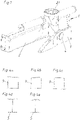
- figure 1 shows a generic crane base 1 according to the prior art with an axle pivot 4 between the base part 2 and the at least one support part 3.
- figure 2 branches off a non-generic crane base 1 according to the prior art, in which the carrier 9 between the base part 2 and the at least one support part 3 is designed to be torsionally rigid.
- Known profile cross-sections of known torsion-resistant carrier 9 are in the Figures 4a to 4c shown.
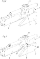
- FIG figure 3 shows an embodiment of a crane base 1 according to the invention.
- the base part 2 has a storage area 21 for storing the rotating part 7 of a loading crane 6 (see FIG figure 5 ) on.
- the base part 2 and the at least one support part 3 are connected via a joint in the form of a torsionally flexible support 5 (see Fig Figure 4f ) connected, one end 51 of the carrier 5 being connected to the base part 2 and the other end 52 of the carrier 5 is connected to the at least one support part 3 .
- the necessary twistability of the base part 2 and at least one support part 3 results solely from the torsionally flexible carrier 5.
Landscapes
- Engineering & Computer Science (AREA)
- General Engineering & Computer Science (AREA)
- Manufacturing & Machinery (AREA)
- Life Sciences & Earth Sciences (AREA)
- Agronomy & Crop Science (AREA)
- Mechanical Engineering (AREA)
- Jib Cranes (AREA)
- Handcart (AREA)
- Motor Power Transmission Devices (AREA)
Description
- Die vorliegende Erfindung betrifft einen Kransockel für einen Ladekran mit den Merkmalen des Oberbegriffs des Anspruchs 1 sowie einen Ladekran mit den Merkmalen des Anspruchs 3 und ein Kraftfahrzeug mit einem solchen Ladekran. Kransockel sind im zentralen Bereich des nicht drehbaren Teils eines Ladekranes angeordnet. In einem Basisteil (meist in Form eines Querholmes ausgebildet) des Kransockels ist ein Lagerbereich für den drehenden Teil des Ladekranes angeordnet. Die Lagerung des drehenden Teils des Ladekranes wird meist mit zwei höhenversetzten Radiallagern und ein oben oder unten liegendes Axiallager (meist Gleitlager) ausgeführt. Im oder am Basisteil befindet sich meist auch der Schwenkantrieb (z. B.: Zahnstangenschwenkantrieb) für den drehbaren Teil des Ladekranes.
- Der Kransockel ist auch das Verbindungselement zur Unterkonstruktion (meist eines Kraftfahrzeuges, z. B. LKW) und wird über wenigstens einen Abstützteil (meist ein sogenannter "Hilfsrahmen") über einen Befestigungsbereich an der Unterkonstruktion befestigt (meist über außen liegende Bleche durch Schrauben).
- Allgemein im Stand der Technik bekannte Kransockel gehen beispielsweise aus der
JP S60 19590 U FR 2 289 429 A1 - Die Unterkonstruktion, also z. B. der LKW-Rahmen, darf durch den über den Basisteil und den wenigstens einen Abstützteil aufgesetzten Kransockel bzw. Ladekran nicht unzulässig verformt bzw. beansprucht werden.
- Um eine statisch bestimmte Krafteinleitung zu erzielen, wird zwischen Basisteil und dem wenigstens einen Abstützteil ein Achszapfgelenk angeordnet (siehe
Figur 1 ). Das über einen runden Lagerzapfen ("Wippenzapfen") gelagerte wenigstens eine Abstützteil wird häufig als "Wippe" bezeichnet und verfügt über eine horizontale Achse. Der Träger zum Lagerzapfen hat eine geschlossene (torsionssteife) Querschnittsform. Sowohl das Basisteil, als auch die Wippe sind mit der Hilfsrahmen Unterkonstruktion starr verbunden, können sich jedoch zueinander um die horizontale Achse (Wippenachse) verdrehen. Das System ist dadurch statisch bestimmt. - Eine andere bekannte Konstruktionsform ist eine starre, einteilige Ausführung des Kransockels ohne das oben beschriebene Drehgelenk (
Figur 2 ). Die Profilform des Trägers zwischen Basisteil und dem wenigstens einen Abstützteil zur Unterkonstruktion ist üblicherweise mit einem geschlossenen (torsionssteifen) Kastenquerschnitt ausgeführt. - Da die Krafteinleitung in den wenigstens einen Abstützteil und über diesen in die Unterkonstruktion hierbei statisch unbestimmt erfolgt, kann die Unterkonstruktion unzulässig beansprucht werden.
- Durch den Entfall des Drehgelenkes ist diese Lösung zwar einfacher und kostengünstiger, aber insbesondere von den Herstellern von Kraftfahrzeugen oft nicht erwünscht.
- Aufgabe der Erfindung ist die Bereitstellung eines Kransockels, eines Ladekrans und eines Kraftfahrzeuges mit einem Ladekran, die zwar statisch bestimmt, jedoch einfacher und kostengünstiger herstellbar sind als die oben diskutierte Lösung mit Hilfe eines Drehgelenks.
- Diese Aufgabe wird durch einen Kransockel mit den Merkmalen des Anspruchs 1, einen Ladekran mit den Merkmalen des Anspruchs 2 und ein Kraftfahrzeug mit den Merkmalen des Anspruchs 3 gelöst.
- Bei der Erfindung ist kein zusätzliches Achszapfgelenk zwischen Basisteil und wenigstens einem Abstützteil vorgesehen. Über den torsionsweichen Träger, der in die Stahlkonstruktion des Kransockels integriert sein kann, dass wird die Gelenkfunktion auch ohne das Achszapfgelenk des Standes der Technik realisiert.
- Dies erfolgt über eine offene Trägerkonstruktion (in "I - Profil Bauweise") in dem Bereich, in welchem sich üblicherweise das Achszapfgelenk befinden würde. Ein offener I - Profilquerschnitt mit entsprechender Länge zeichnet sich durch eine geringe Torsions- bzw. Verdrehsteifigkeit, jedoch hohe Biegesteifigkeit, aus. Die auftretenden, geringfügigen Verdrehungen können daher über den Träger geleitet werden, ohne dass dieser dadurch statisch (durch Torsion) überlastet wird. Die Übertragung aller übrigen Kräfte bzw. Momente im Kranbetrieb ist uneingeschränkt möglich. Die Funktion einer derartigen Konstruktion ist mit jener mit "Wippenzapfen" praktisch identisch, jedoch mit geringerem Aufwand herzustellen.
- Weitere Details des Standes der Technik und der Erfindung sind in den Figuren erkennbar. Es zeigen:
- Figur 1
- eine erste Lösung nach dem Stand der Technik mit einem Drehgelenk,
- Figur 2
- eine zweite Lösung nach dem Stand der Technik, die statisch unbestimmt ist,
- Figur 3
- ein Ausführungsbeispiel der Erfindung,
- Figur 4a-4c
- Profilquerschnitte nach dem Stand der Technik,
- Figur 4d, 4e
- Profilquerschnitte nach der Erfindung,
- Figur 4f
- eine perspektivische Ansicht des zum Profilquerschnitt nach
Figur 4e gehörenden Trägers, - Figur 5
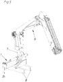
- eine perspektivische Ansicht eines erfindungsgemäßen Ladekrans samt Unterkonstruktion.
-
Figur 1 zeigt einen gattungsgemäßen Kransockel 1 nach dem Stand der Technik mit einem Achszapfgelenk 4 zwischen dem Basisteil 2 und dem wenigstens einen Abstützteil 3. -
Figur 2 zweigt einen nicht gattungsgemäßen Kransockel 1 nach dem Stand der Technik, bei dem der Träger 9 zwischen dem Basisteil 2 und dem wenigstens einen Abstützteil 3 torsionssteif ausgebildet ist. Bekannte Profilquerschnitte bekannter torsionssteifer Träger 9 sind in denFiguren 4a bis 4c dargestellt. -
Figur 3 zeigt ein Ausführungsbeispiel eines Kransockels 1 nach der Erfindung. Der Basisteil 2 weist einen Lagerbereich 21 zur Lagerung des drehenden Teils 7 eines Ladekrans 6 (sieheFigur 5 ) auf. Das Basisteil 2 und der wenigstens eine Abstützteil 3 sind über ein Gelenk in Form eines torsionsweichen Trägers 5 (sieheFigur 4f ) verbunden, wobei das eine Ende 51 des Trägers 5 mit dem Basisteil 2 verbunden ist und das andere Ende 52 des Trägers 5 mit dem wenigstens einen Abstützteil 3 verbunden ist. Es ist kein Drehgelenk zwischen Basisteil 2 und wenigstens einem Abstützteil 3 vorgesehen. Die notwendige Verdrehbarkeit von Basisteil 2 und wenigstens einem Abstützteil 3 ergibt sich allein durch den torsionsweichen Träger 5. - Der zu diesem Träger 5 gehörende Profilquerschnitt ist in
Figur 4d dargestellt.Figur 4e zeigt eine Alternative. Die offene Ausbildung des Trägers 5 ist wichtig, da sich hierdurch die Torsionsweichheit ergibt.
Claims (3)
- Kransockel (1) für einen Ladekran (6), mit- einem Basisteil (2), welches über einen Lagerbereich (21) zur Lagerung des drehenden Teils (7) eines Ladekrans (6) verfügt,- wenigstens einem Abstützteil (3), welches der zusätzlichen Abstützung des Kransockels (1) an einer Unterkonstruktion (8) dient,- einem Gelenk (4), welches den Basisteil (2) und den wenigstens einen Abstützteil (3) miteinander verbindet,dadurch gekennzeichnet, dass das Gelenk (4) in Form eines torsionsweichen Trägers (5) ausgebildet ist, wobei das eine Ende (51) des Trägers (5) mit dem Basisteil (2) verbunden ist und das andere Ende (52) des Trägers (5) mit dem wenigstens einen Abstützteil (3) verbunden ist, wobei der Basisteil (2) und der wenigstens eine Abstützteil (3) nur über das Gelenk (4) in Form eines torsionsweichen Trägers (5) verbunden sind, wobei der Träger (5) als I-Profil mit einem offenen Profilquerschnitt ausgebildet ist.
- Ladekran (6) mit einem Kransockel (1) nach Anspruch 1.
- Kraftfahrzeug mit einer Unterkonstruktion (8), an welcher ein Kransockel (1) nach Anspruch 1 oder ein Ladekran (6) nach Anspruch 2 befestigt ist.
Priority Applications (1)
| Application Number | Priority Date | Filing Date | Title |
|---|---|---|---|
| PL15715123T PL3105164T3 (pl) | 2014-02-14 | 2015-02-09 | Cokół żurawia dla żurawia ładunkowego |
Applications Claiming Priority (2)
| Application Number | Priority Date | Filing Date | Title |
|---|---|---|---|
| AT662014 | 2014-02-14 | ||
| PCT/AT2015/000019 WO2015120494A1 (de) | 2014-02-14 | 2015-02-09 | Kransockel für einen ladekran |
Publications (3)
| Publication Number | Publication Date |
|---|---|
| EP3105164A1 EP3105164A1 (de) | 2016-12-21 |
| EP3105164B1 EP3105164B1 (de) | 2017-10-04 |
| EP3105164B2 true EP3105164B2 (de) | 2022-03-30 |
Family
ID=53799434
Family Applications (1)
| Application Number | Title | Priority Date | Filing Date |
|---|---|---|---|
| EP15715123.4A Active EP3105164B2 (de) | 2014-02-14 | 2015-02-09 | Kransockel für einen ladekran |
Country Status (9)
| Country | Link |
|---|---|
| US (1) | US10322914B2 (de) |
| EP (1) | EP3105164B2 (de) |
| CN (1) | CN105980288B (de) |
| CA (1) | CA2939141C (de) |
| DK (1) | DK3105164T3 (de) |
| ES (1) | ES2655139T3 (de) |
| PL (1) | PL3105164T3 (de) |
| RU (1) | RU2638058C1 (de) |
| WO (1) | WO2015120494A1 (de) |
Families Citing this family (2)
| Publication number | Priority date | Publication date | Assignee | Title |
|---|---|---|---|---|
| EP3105164B2 (de) | 2014-02-14 | 2022-03-30 | Palfinger AG | Kransockel für einen ladekran |
| BE1030526B1 (nl) * | 2022-05-16 | 2023-12-11 | Werkhuizen Jacobs | Rolkraan voor een transportvoertuig met een standaard autolaadkraan met een derde punt en werkwijze voor de bouw van zulke rolkraan |
Family Cites Families (13)
| Publication number | Priority date | Publication date | Assignee | Title |
|---|---|---|---|---|
| US2369816A (en) * | 1943-07-17 | 1945-02-20 | Beatty M Crawford | Power mast and boom hoist |
| US2957678A (en) * | 1958-08-14 | 1960-10-25 | Eldon D Jones | Hydraulic hoist attachment for tractors |
| DE1229263B (de) | 1963-11-18 | 1966-11-24 | Meiller Fahrzeuge | Lastkraftfahrzeug mit Ladekran |
| SE354461B (de) | 1971-05-21 | 1973-03-12 | Bil City I Pitea Ab | |
| SE385826B (sv) * | 1974-10-22 | 1976-07-26 | Hiab Foco Ab | Ledbrygga till lastkran |
| JPS6019590U (ja) * | 1983-07-15 | 1985-02-09 | 株式会社 多田野鉄工所 | 搭載型クレ−ンの取付構造 |
| JPS6019590A (ja) | 1983-07-15 | 1985-01-31 | Ricoh Co Ltd | 感熱転写シ−ト |
| US7328810B1 (en) | 2003-12-22 | 2008-02-12 | Lester Kent Rhodes | Crane supporting apparatus |
| DE102005041255A1 (de) * | 2005-08-31 | 2007-03-01 | Terex-Demag Gmbh & Co. Kg | Transportoptimierter Kranunterwagen |
| RU67082U1 (ru) * | 2007-01-30 | 2007-10-10 | ОАО "Головной специализированный конструкторско-технологический институт" (ОАО "ГСКТИ") | Механизм поворота крана |
| CN101607574A (zh) * | 2009-07-20 | 2009-12-23 | 长沙中联重工科技发展股份有限公司 | 履带式底盘及具有该底盘的工程机械 |
| EP3105164B2 (de) | 2014-02-14 | 2022-03-30 | Palfinger AG | Kransockel für einen ladekran |
| AU2015201624A1 (en) * | 2014-03-28 | 2015-10-15 | Liftow Ride Pty Ltd | A tow bar attachment |
-
2015
- 2015-02-09 EP EP15715123.4A patent/EP3105164B2/de active Active
- 2015-02-09 DK DK15715123.4T patent/DK3105164T3/en active
- 2015-02-09 WO PCT/AT2015/000019 patent/WO2015120494A1/de not_active Ceased
- 2015-02-09 CA CA2939141A patent/CA2939141C/en not_active Expired - Fee Related
- 2015-02-09 RU RU2016136677A patent/RU2638058C1/ru active
- 2015-02-09 ES ES15715123.4T patent/ES2655139T3/es active Active
- 2015-02-09 PL PL15715123T patent/PL3105164T3/pl unknown
- 2015-02-09 CN CN201580008308.3A patent/CN105980288B/zh not_active Expired - Fee Related
-
2016
- 2016-08-12 US US15/235,459 patent/US10322914B2/en not_active Expired - Fee Related
Non-Patent Citations (1)
| Title |
|---|
| ANONYMOUS: "Reservdelskatalog Spare Parts Catalogue HIAB 93", HIAB HYDRAULISKA INDUSTRI AB, 1 June 1969 (1969-06-01), pages 32pp † |
Also Published As
| Publication number | Publication date |
|---|---|
| EP3105164A1 (de) | 2016-12-21 |
| CN105980288A (zh) | 2016-09-28 |
| EP3105164B1 (de) | 2017-10-04 |
| US10322914B2 (en) | 2019-06-18 |
| CA2939141C (en) | 2018-07-24 |
| ES2655139T3 (es) | 2018-02-19 |
| RU2638058C1 (ru) | 2017-12-11 |
| WO2015120494A1 (de) | 2015-08-20 |
| CN105980288B (zh) | 2019-03-19 |
| DK3105164T3 (en) | 2018-01-02 |
| PL3105164T3 (pl) | 2018-03-30 |
| US20160347589A1 (en) | 2016-12-01 |
| CA2939141A1 (en) | 2015-08-20 |
Similar Documents
| Publication | Publication Date | Title |
|---|---|---|
| DE102007049864B4 (de) | Sitzgestell eines Kraftfahrzeugsitzes mit einem Sitzträger, der zwei Seitenteile hat | |
| DE102015015520B4 (de) | Drehstabfederungsstruktur | |
| EP3551519B1 (de) | Drehgestell eines schienenfahrzeugs mit mindestens zwei in achslagern gelagerten radsätzen und wenigstens einem querträger | |
| DE102012214352A1 (de) | Einzelradaufhängung | |
| EP2604453A1 (de) | Blattfeder mit einem starr verbundenen elastischen Verbindungskörper für ein Kraftfahrzeug | |
| EP2697083A1 (de) | Schwenklager | |
| DE102014201876A1 (de) | Vorrichtung zum Einstellen der Spur und/oder des Sturzes für ein Fahrwerk eines Kraftfahrzeugs | |
| DE102015211529A1 (de) | Einzelradaufhängung | |
| DE102013106385B4 (de) | Scharniervorrichtung | |
| WO2017102197A1 (de) | Motorlager-pendelstützen-vorrichtung | |
| EP3105164B2 (de) | Kransockel für einen ladekran | |
| DE102012203178A1 (de) | Kraftübertragungseinrichtung eines Drehflügelflugzeugs | |
| DE3540590A1 (de) | Anordnung zur aufnahme radialer belastungen bei einem drehofen | |
| DE102004002550A1 (de) | Doppelter Schwenkmotor und Verfahren zur Ansteuerung | |
| DE1030697B (de) | Aufhaengung fuer die Hinterraeder eines Fahrzeuges | |
| EP2955040A2 (de) | Lenkerverschraubung eines lenkers eines fahrwerks eines kraftfahrzeugs | |
| DE2721399A1 (de) | Feder | |
| EP3456887A1 (de) | Baggerausleger und bagger | |
| EP3412484B1 (de) | Aggregatlagerung für ein kraftfahrzeug | |
| EP3342688A1 (de) | Kabinenhubgestell für ein materialumschlaggerät | |
| EP4344920B1 (de) | Haltestruktur | |
| EP2525928B2 (de) | Strangführungselement zum führen und stützen eines metallischen strangs in einer stranggiessmaschine | |
| EP2274590B1 (de) | Rollenprüfstand für kraftfahrzeuge | |
| DE102007049113A1 (de) | Einschaliger Querlenker | |
| EP2544929B1 (de) | Vorrichtung zur lagerung einer seitenwaschbürste und fahrzeugwaschanlage mit einer derartigen vorrichtung |
Legal Events
| Date | Code | Title | Description |
|---|---|---|---|
| PUAI | Public reference made under article 153(3) epc to a published international application that has entered the european phase |
Free format text: ORIGINAL CODE: 0009012 |
|
| STAA | Information on the status of an ep patent application or granted ep patent |
Free format text: STATUS: REQUEST FOR EXAMINATION WAS MADE |
|
| 17P | Request for examination filed |
Effective date: 20160809 |
|
| AK | Designated contracting states |
Kind code of ref document: A1 Designated state(s): AL AT BE BG CH CY CZ DE DK EE ES FI FR GB GR HR HU IE IS IT LI LT LU LV MC MK MT NL NO PL PT RO RS SE SI SK SM TR |
|
| AX | Request for extension of the european patent |
Extension state: BA ME |
|
| GRAP | Despatch of communication of intention to grant a patent |
Free format text: ORIGINAL CODE: EPIDOSNIGR1 |
|
| STAA | Information on the status of an ep patent application or granted ep patent |
Free format text: STATUS: GRANT OF PATENT IS INTENDED |
|
| DAX | Request for extension of the european patent (deleted) | ||
| INTG | Intention to grant announced |
Effective date: 20170511 |
|
| GRAS | Grant fee paid |
Free format text: ORIGINAL CODE: EPIDOSNIGR3 |
|
| GRAA | (expected) grant |
Free format text: ORIGINAL CODE: 0009210 |
|
| STAA | Information on the status of an ep patent application or granted ep patent |
Free format text: STATUS: THE PATENT HAS BEEN GRANTED |
|
| TPAC | Observations filed by third parties |
Free format text: ORIGINAL CODE: EPIDOSNTIPA |
|
| RIN1 | Information on inventor provided before grant (corrected) |
Inventor name: WIMMER, ECKHARD |
|
| AK | Designated contracting states |
Kind code of ref document: B1 Designated state(s): AL AT BE BG CH CY CZ DE DK EE ES FI FR GB GR HR HU IE IS IT LI LT LU LV MC MK MT NL NO PL PT RO RS SE SI SK SM TR |
|
| RAP1 | Party data changed (applicant data changed or rights of an application transferred) |
Owner name: PALFINGER AG |
|
| REG | Reference to a national code |
Ref country code: GB Ref legal event code: FG4D Free format text: NOT ENGLISH |
|
| REG | Reference to a national code |
Ref country code: CH Ref legal event code: EP |
|
| REG | Reference to a national code |
Ref country code: AT Ref legal event code: REF Ref document number: 933811 Country of ref document: AT Kind code of ref document: T Effective date: 20171015 |
|
| REG | Reference to a national code |
Ref country code: IE Ref legal event code: FG4D Free format text: LANGUAGE OF EP DOCUMENT: GERMAN |
|
| REG | Reference to a national code |
Ref country code: DE Ref legal event code: R096 Ref document number: 502015002020 Country of ref document: DE |
|
| REG | Reference to a national code |
Ref country code: SE Ref legal event code: TRGR Ref country code: DK Ref legal event code: T3 Effective date: 20171221 |
|
| REG | Reference to a national code |
Ref country code: NL Ref legal event code: MP Effective date: 20171004 |
|
| REG | Reference to a national code |
Ref country code: ES Ref legal event code: FG2A Ref document number: 2655139 Country of ref document: ES Kind code of ref document: T3 Effective date: 20180219 |
|
| REG | Reference to a national code |
Ref country code: LT Ref legal event code: MG4D Ref country code: FR Ref legal event code: PLFP Year of fee payment: 4 |
|
| PG25 | Lapsed in a contracting state [announced via postgrant information from national office to epo] |
Ref country code: NL Free format text: LAPSE BECAUSE OF FAILURE TO SUBMIT A TRANSLATION OF THE DESCRIPTION OR TO PAY THE FEE WITHIN THE PRESCRIBED TIME-LIMIT Effective date: 20171004 |
|
| PG25 | Lapsed in a contracting state [announced via postgrant information from national office to epo] |
Ref country code: NO Free format text: LAPSE BECAUSE OF FAILURE TO SUBMIT A TRANSLATION OF THE DESCRIPTION OR TO PAY THE FEE WITHIN THE PRESCRIBED TIME-LIMIT Effective date: 20180104 Ref country code: LT Free format text: LAPSE BECAUSE OF FAILURE TO SUBMIT A TRANSLATION OF THE DESCRIPTION OR TO PAY THE FEE WITHIN THE PRESCRIBED TIME-LIMIT Effective date: 20171004 |
|
| PG25 | Lapsed in a contracting state [announced via postgrant information from national office to epo] |
Ref country code: IS Free format text: LAPSE BECAUSE OF FAILURE TO SUBMIT A TRANSLATION OF THE DESCRIPTION OR TO PAY THE FEE WITHIN THE PRESCRIBED TIME-LIMIT Effective date: 20180204 Ref country code: GR Free format text: LAPSE BECAUSE OF FAILURE TO SUBMIT A TRANSLATION OF THE DESCRIPTION OR TO PAY THE FEE WITHIN THE PRESCRIBED TIME-LIMIT Effective date: 20180105 Ref country code: HR Free format text: LAPSE BECAUSE OF FAILURE TO SUBMIT A TRANSLATION OF THE DESCRIPTION OR TO PAY THE FEE WITHIN THE PRESCRIBED TIME-LIMIT Effective date: 20171004 Ref country code: RS Free format text: LAPSE BECAUSE OF FAILURE TO SUBMIT A TRANSLATION OF THE DESCRIPTION OR TO PAY THE FEE WITHIN THE PRESCRIBED TIME-LIMIT Effective date: 20171004 Ref country code: LV Free format text: LAPSE BECAUSE OF FAILURE TO SUBMIT A TRANSLATION OF THE DESCRIPTION OR TO PAY THE FEE WITHIN THE PRESCRIBED TIME-LIMIT Effective date: 20171004 Ref country code: BG Free format text: LAPSE BECAUSE OF FAILURE TO SUBMIT A TRANSLATION OF THE DESCRIPTION OR TO PAY THE FEE WITHIN THE PRESCRIBED TIME-LIMIT Effective date: 20180104 |
|
| REG | Reference to a national code |
Ref country code: DE Ref legal event code: R026 Ref document number: 502015002020 Country of ref document: DE |
|
| PLBI | Opposition filed |
Free format text: ORIGINAL CODE: 0009260 |
|
| PLAX | Notice of opposition and request to file observation + time limit sent |
Free format text: ORIGINAL CODE: EPIDOSNOBS2 |
|
| 26 | Opposition filed |
Opponent name: CARGOTEC PATENTER AB Effective date: 20180619 |
|
| PG25 | Lapsed in a contracting state [announced via postgrant information from national office to epo] |
Ref country code: EE Free format text: LAPSE BECAUSE OF FAILURE TO SUBMIT A TRANSLATION OF THE DESCRIPTION OR TO PAY THE FEE WITHIN THE PRESCRIBED TIME-LIMIT Effective date: 20171004 Ref country code: CZ Free format text: LAPSE BECAUSE OF FAILURE TO SUBMIT A TRANSLATION OF THE DESCRIPTION OR TO PAY THE FEE WITHIN THE PRESCRIBED TIME-LIMIT Effective date: 20171004 Ref country code: SK Free format text: LAPSE BECAUSE OF FAILURE TO SUBMIT A TRANSLATION OF THE DESCRIPTION OR TO PAY THE FEE WITHIN THE PRESCRIBED TIME-LIMIT Effective date: 20171004 |
|
| PG25 | Lapsed in a contracting state [announced via postgrant information from national office to epo] |
Ref country code: SM Free format text: LAPSE BECAUSE OF FAILURE TO SUBMIT A TRANSLATION OF THE DESCRIPTION OR TO PAY THE FEE WITHIN THE PRESCRIBED TIME-LIMIT Effective date: 20171004 Ref country code: RO Free format text: LAPSE BECAUSE OF FAILURE TO SUBMIT A TRANSLATION OF THE DESCRIPTION OR TO PAY THE FEE WITHIN THE PRESCRIBED TIME-LIMIT Effective date: 20171004 |
|
| REG | Reference to a national code |
Ref country code: CH Ref legal event code: PL |
|
| PG25 | Lapsed in a contracting state [announced via postgrant information from national office to epo] |
Ref country code: MC Free format text: LAPSE BECAUSE OF FAILURE TO SUBMIT A TRANSLATION OF THE DESCRIPTION OR TO PAY THE FEE WITHIN THE PRESCRIBED TIME-LIMIT Effective date: 20171004 Ref country code: MT Free format text: LAPSE BECAUSE OF FAILURE TO SUBMIT A TRANSLATION OF THE DESCRIPTION OR TO PAY THE FEE WITHIN THE PRESCRIBED TIME-LIMIT Effective date: 20171004 |
|
| PLBB | Reply of patent proprietor to notice(s) of opposition received |
Free format text: ORIGINAL CODE: EPIDOSNOBS3 |
|
| REG | Reference to a national code |
Ref country code: IE Ref legal event code: MM4A |
|
| REG | Reference to a national code |
Ref country code: BE Ref legal event code: MM Effective date: 20180228 |
|
| PG25 | Lapsed in a contracting state [announced via postgrant information from national office to epo] |
Ref country code: CH Free format text: LAPSE BECAUSE OF NON-PAYMENT OF DUE FEES Effective date: 20180228 Ref country code: LI Free format text: LAPSE BECAUSE OF NON-PAYMENT OF DUE FEES Effective date: 20180228 Ref country code: LU Free format text: LAPSE BECAUSE OF NON-PAYMENT OF DUE FEES Effective date: 20180209 Ref country code: SI Free format text: LAPSE BECAUSE OF FAILURE TO SUBMIT A TRANSLATION OF THE DESCRIPTION OR TO PAY THE FEE WITHIN THE PRESCRIBED TIME-LIMIT Effective date: 20171004 |
|
| PG25 | Lapsed in a contracting state [announced via postgrant information from national office to epo] |
Ref country code: IE Free format text: LAPSE BECAUSE OF NON-PAYMENT OF DUE FEES Effective date: 20180209 |
|
| PG25 | Lapsed in a contracting state [announced via postgrant information from national office to epo] |
Ref country code: BE Free format text: LAPSE BECAUSE OF NON-PAYMENT OF DUE FEES Effective date: 20180228 |
|
| GBPC | Gb: european patent ceased through non-payment of renewal fee |
Effective date: 20190209 |
|
| PG25 | Lapsed in a contracting state [announced via postgrant information from national office to epo] |
Ref country code: GB Free format text: LAPSE BECAUSE OF NON-PAYMENT OF DUE FEES Effective date: 20190209 |
|
| PG25 | Lapsed in a contracting state [announced via postgrant information from national office to epo] |
Ref country code: PT Free format text: LAPSE BECAUSE OF FAILURE TO SUBMIT A TRANSLATION OF THE DESCRIPTION OR TO PAY THE FEE WITHIN THE PRESCRIBED TIME-LIMIT Effective date: 20171004 |
|
| PG25 | Lapsed in a contracting state [announced via postgrant information from national office to epo] |
Ref country code: MK Free format text: LAPSE BECAUSE OF NON-PAYMENT OF DUE FEES Effective date: 20171004 Ref country code: HU Free format text: LAPSE BECAUSE OF FAILURE TO SUBMIT A TRANSLATION OF THE DESCRIPTION OR TO PAY THE FEE WITHIN THE PRESCRIBED TIME-LIMIT; INVALID AB INITIO Effective date: 20150209 Ref country code: CY Free format text: LAPSE BECAUSE OF FAILURE TO SUBMIT A TRANSLATION OF THE DESCRIPTION OR TO PAY THE FEE WITHIN THE PRESCRIBED TIME-LIMIT Effective date: 20171004 |
|
| PG25 | Lapsed in a contracting state [announced via postgrant information from national office to epo] |
Ref country code: AL Free format text: LAPSE BECAUSE OF FAILURE TO SUBMIT A TRANSLATION OF THE DESCRIPTION OR TO PAY THE FEE WITHIN THE PRESCRIBED TIME-LIMIT Effective date: 20171004 |
|
| PLAY | Examination report in opposition despatched + time limit |
Free format text: ORIGINAL CODE: EPIDOSNORE2 |
|
| PLBC | Reply to examination report in opposition received |
Free format text: ORIGINAL CODE: EPIDOSNORE3 |
|
| PGFP | Annual fee paid to national office [announced via postgrant information from national office to epo] |
Ref country code: FR Payment date: 20210223 Year of fee payment: 7 Ref country code: IT Payment date: 20210223 Year of fee payment: 7 Ref country code: FI Payment date: 20210218 Year of fee payment: 7 |
|
| PGFP | Annual fee paid to national office [announced via postgrant information from national office to epo] |
Ref country code: PL Payment date: 20210201 Year of fee payment: 7 Ref country code: TR Payment date: 20210201 Year of fee payment: 7 Ref country code: SE Payment date: 20210219 Year of fee payment: 7 Ref country code: ES Payment date: 20210316 Year of fee payment: 7 Ref country code: DK Payment date: 20210219 Year of fee payment: 7 Ref country code: AT Payment date: 20210225 Year of fee payment: 7 |
|
| PGFP | Annual fee paid to national office [announced via postgrant information from national office to epo] |
Ref country code: DE Payment date: 20210427 Year of fee payment: 7 |
|
| RIC2 | Information provided on ipc code assigned after grant |
Ipc: B66C 23/44 20060101AFI20210706BHEP Ipc: F42B 3/103 20060101ALI20210706BHEP Ipc: F42B 3/195 20060101ALI20210706BHEP Ipc: F42B 3/198 20060101ALI20210706BHEP |
|
| PUAH | Patent maintained in amended form |
Free format text: ORIGINAL CODE: 0009272 |
|
| STAA | Information on the status of an ep patent application or granted ep patent |
Free format text: STATUS: PATENT MAINTAINED AS AMENDED |
|
| 27A | Patent maintained in amended form |
Effective date: 20220330 |
|
| AK | Designated contracting states |
Kind code of ref document: B2 Designated state(s): AL AT BE BG CH CY CZ DE DK EE ES FI FR GB GR HR HU IE IS IT LI LT LU LV MC MK MT NL NO PL PT RO RS SE SI SK SM TR |
|
| REG | Reference to a national code |
Ref country code: DE Ref legal event code: R102 Ref document number: 502015002020 Country of ref document: DE |
|
| REG | Reference to a national code |
Ref country code: SE Ref legal event code: NAV |
|
| PG25 | Lapsed in a contracting state [announced via postgrant information from national office to epo] |
Ref country code: FI Free format text: LAPSE BECAUSE OF FAILURE TO SUBMIT A TRANSLATION OF THE DESCRIPTION OR TO PAY THE FEE WITHIN THE PRESCRIBED TIME-LIMIT Effective date: 20220330 |
|
| REG | Reference to a national code |
Ref country code: DE Ref legal event code: R119 Ref document number: 502015002020 Country of ref document: DE |
|
| REG | Reference to a national code |
Ref country code: AT Ref legal event code: MM01 Ref document number: 933811 Country of ref document: AT Kind code of ref document: T Effective date: 20220209 |
|
| PG25 | Lapsed in a contracting state [announced via postgrant information from national office to epo] |
Ref country code: ES Free format text: LAPSE BECAUSE OF FAILURE TO SUBMIT A TRANSLATION OF THE DESCRIPTION OR TO PAY THE FEE WITHIN THE PRESCRIBED TIME-LIMIT Effective date: 20220330 Ref country code: AT Free format text: LAPSE BECAUSE OF NON-PAYMENT OF DUE FEES Effective date: 20220209 |
|
| PG25 | Lapsed in a contracting state [announced via postgrant information from national office to epo] |
Ref country code: FR Free format text: LAPSE BECAUSE OF NON-PAYMENT OF DUE FEES Effective date: 20220228 |
|
| PG25 | Lapsed in a contracting state [announced via postgrant information from national office to epo] |
Ref country code: DK Free format text: LAPSE BECAUSE OF FAILURE TO SUBMIT A TRANSLATION OF THE DESCRIPTION OR TO PAY THE FEE WITHIN THE PRESCRIBED TIME-LIMIT Effective date: 20220330 Ref country code: DE Free format text: LAPSE BECAUSE OF NON-PAYMENT OF DUE FEES Effective date: 20220901 |
|
| PG25 | Lapsed in a contracting state [announced via postgrant information from national office to epo] |
Ref country code: IT Free format text: LAPSE BECAUSE OF NON-PAYMENT OF DUE FEES Effective date: 20220209 |
|
| PG25 | Lapsed in a contracting state [announced via postgrant information from national office to epo] |
Ref country code: PL Free format text: LAPSE BECAUSE OF NON-PAYMENT OF DUE FEES Effective date: 20220209 |
|
| PG25 | Lapsed in a contracting state [announced via postgrant information from national office to epo] |
Ref country code: PL Free format text: LAPSE BECAUSE OF NON-PAYMENT OF DUE FEES Effective date: 20220209 |
|
| PG25 | Lapsed in a contracting state [announced via postgrant information from national office to epo] |
Ref country code: SE Free format text: LAPSE BECAUSE OF NON-PAYMENT OF DUE FEES Effective date: 20220210 |