EP3105104B1 - Tugger and rider cart assembly - Google Patents
Tugger and rider cart assembly Download PDFInfo
- Publication number
- EP3105104B1 EP3105104B1 EP14882216.6A EP14882216A EP3105104B1 EP 3105104 B1 EP3105104 B1 EP 3105104B1 EP 14882216 A EP14882216 A EP 14882216A EP 3105104 B1 EP3105104 B1 EP 3105104B1
- Authority
- EP
- European Patent Office
- Prior art keywords
- tugger
- cart
- rider
- attached
- pedal
- Prior art date
- Legal status (The legal status is an assumption and is not a legal conclusion. Google has not performed a legal analysis and makes no representation as to the accuracy of the status listed.)
- Not-in-force
Links
- 238000005096 rolling process Methods 0.000 claims description 3
- 230000000903 blocking effect Effects 0.000 claims description 2
- 239000000463 material Substances 0.000 description 3
- 239000002184 metal Substances 0.000 description 2
- 238000012423 maintenance Methods 0.000 description 1
- 238000000034 method Methods 0.000 description 1
- 238000012986 modification Methods 0.000 description 1
- 230000004048 modification Effects 0.000 description 1
Images


Classifications
-
- B—PERFORMING OPERATIONS; TRANSPORTING
- B62—LAND VEHICLES FOR TRAVELLING OTHERWISE THAN ON RAILS
- B62B—HAND-PROPELLED VEHICLES, e.g. HAND CARTS OR PERAMBULATORS; SLEDGES
- B62B3/00—Hand carts having more than one axis carrying transport wheels; Steering devices therefor; Equipment therefor
- B62B3/04—Hand carts having more than one axis carrying transport wheels; Steering devices therefor; Equipment therefor involving means for grappling or securing in place objects to be carried; Loading or unloading equipment
- B62B3/06—Hand carts having more than one axis carrying transport wheels; Steering devices therefor; Equipment therefor involving means for grappling or securing in place objects to be carried; Loading or unloading equipment for simply clearing the load from the ground
-
- B—PERFORMING OPERATIONS; TRANSPORTING
- B62—LAND VEHICLES FOR TRAVELLING OTHERWISE THAN ON RAILS
- B62D—MOTOR VEHICLES; TRAILERS
- B62D53/00—Tractor-trailer combinations; Road trains
- B62D53/005—Combinations with at least three axles and comprising two or more articulated parts
-
- B—PERFORMING OPERATIONS; TRANSPORTING
- B62—LAND VEHICLES FOR TRAVELLING OTHERWISE THAN ON RAILS
- B62B—HAND-PROPELLED VEHICLES, e.g. HAND CARTS OR PERAMBULATORS; SLEDGES
- B62B3/00—Hand carts having more than one axis carrying transport wheels; Steering devices therefor; Equipment therefor
- B62B3/08—Hand carts having more than one axis carrying transport wheels; Steering devices therefor; Equipment therefor involving tiltably-mounted containers
-
- B—PERFORMING OPERATIONS; TRANSPORTING
- B62—LAND VEHICLES FOR TRAVELLING OTHERWISE THAN ON RAILS
- B62D—MOTOR VEHICLES; TRAILERS
- B62D63/00—Motor vehicles or trailers not otherwise provided for
- B62D63/06—Trailers
-
- B—PERFORMING OPERATIONS; TRANSPORTING
- B62—LAND VEHICLES FOR TRAVELLING OTHERWISE THAN ON RAILS
- B62B—HAND-PROPELLED VEHICLES, e.g. HAND CARTS OR PERAMBULATORS; SLEDGES
- B62B2202/00—Indexing codes relating to type or characteristics of transported articles
- B62B2202/90—Vehicles
-
- B—PERFORMING OPERATIONS; TRANSPORTING
- B62—LAND VEHICLES FOR TRAVELLING OTHERWISE THAN ON RAILS
- B62B—HAND-PROPELLED VEHICLES, e.g. HAND CARTS OR PERAMBULATORS; SLEDGES
- B62B2207/00—Joining hand-propelled vehicles or sledges together
- B62B2207/02—Joining hand-propelled vehicles or sledges together rigidly
Definitions
- the present invention relates to a tugger cart and a tugger cart apparatus.
- the tugger truck pulls a train of tugger carts, with push carts on board, from location to location in a factory or warehouse.
- the push carts are loaded with material at a picking station or supermarket. They are then loaded on to the tugger carts. After that, they are tugged to the unload area, unloaded off of the tugger carts, and pushed into their final position on the assembly line.
- the empty tugger carts may be reloaded with empty push carts and returned to the picking station.
- a tugger cart comprising a tugger frame, a plurality of guide wheels attached within an inside portion of the tugger frame and a plurality of casters attached to the bottom of the tugger frame.
- the tugger frame comprises a locking portion which is configured to releasably secure a rider cart to the tugger frame when the rider cart is rolled onto the plurality of guide wheels.
- Document DE 10 2011 100145 A1 discloses a trailer having a supporting frame for receiving a load, and a front chassis and a rear chassis, where the roller tracks are provided in the supporting frame and are transversely arranged with respect to the longitudinal axis of the trailer.
- a releasable locking unit is arranged in the supporting frame for locking the load.
- roller balls are arranged in outer edge of roller tracks.
- a tugger cart comprises: a tugger frame comprising a bottom, a top, a first side, a second side, a locking portion, a front end and a rear end, wherein the first side, the second side, and the locking portion are joined together, wherein the first side, and the second side form an inside portion in between, and an outside portion; a plurality of guide wheels attached within the inside portion of the frame, wherein the plurality of guide wheels together form a slanted line slanting upward from the front end to the rear end; and a plurality of casters attached to the bottom of the tugger frame; wherein the locking portion is configured to releasably secure a rider cart to the tugger frame when the rider cart is rolled onto the plurality of guide wheels.
- the locking portion comprises a latch system comprising at least one rocking arm pivotally attached at a pivot point, wherein the at least one rocking arm comprises a lock pedal near the rear end, an unlock pedal near the front end, and at least one locking peg protruding upwards from the at least one rocking arm, wherein the lock pedal is biased in an upward position and the unlock pedal is biased in a downward position, and wherein when the lock pedal is forced downward the unlock pedal and the at least one locking peg are forced upward.
- an embodiment of the present invention provides a tugger cart that has a first side, a second side and a locking portion.
- the first side and second side may include guide wheels aligned in an upward slant.
- the locking portion may include a rocking arm that is pivotally attached to the tugger cart.
- the rocking arm may include a lock pedal and an unlock pedal.
- a rider cart may include a first side and a second side.
- the first and second side may include wings that are slanted upward, similar to the guide wheels.
- the rider cart may be pushed onto the tugger cart and the wings may roll along the guide wheels.
- the rider cart may apply pressure to the lock pedal and the unlock pedal may pivot upward, locking the rider cart onto the tugger cart.
- the unlock pedal may be pushed downward, and the rider cart may be removed.
- the present invention may include a loading system that allows a push cart to be loaded on a tugger cart. As the push cart is loaded on the tugger cart the present invention may elevate the push cart using a lift system. For unloading, the operator releases the push cart which slowly rolls off of the tugger cart.
- the lift functionality allows the push carts to have two swivel casters and two fixed casters which make the carts more controllable than a push cart with four swivel casters.
- the present invention may also eliminate the need to pull the push cart off of the tugger cart which is a very difficult motion.
- the lift functionality may be achieved by pushing the push cart up a slight incline.
- the present invention may improve operator control when pushing the push carts and ergonomics of unloading.
- there may be multiple guide wheels with equal spacing in a row on the both sides of the inside of the tugger carts.
- the first guide wheel may be lower than the last guide wheel making an incline at a slight angle.
- the push cart may have a metal wing located on both sides positioned at a slight angle. When an operator pushes the push cart on to the tugger cart the metal wings on the push cart roll on top of the rows of guide wheels on the tugger cart and lifts the push cart off of the ground.
- the push cart is unlocked from the tugger cart, the wings on the push cart roll on top of the rows of guide wheels on the tugger cart, lowering the cart to ground level as it comes out.
- the present invention may include a tugger cart 10.
- the tugger cart 10 may have a tugger frame 14.
- the tugger frame 14 may include a bottom, a top, a first side 11, a second side 13, a locking portion 15, a front end 17, and a rear end 19.
- the locking portion 15 may be a middle section in between the first side 11 and the second side 13.
- the first side 11, the locking portion 15, and the second side 13 may be joined together at the rear end 19 and may form channels in between.
- the first side 11 and the second side 13 may form an inside portion 21 and an outside portion 23.
- a plurality of casters 30, 32 may be attached to the bottom of the tugger frame 14.
- a swivel caster 30 may be attached to the bottom of the first side 11 and second side 13, and a pair of fixed casters 32 may be attached to the middle section.
- a plurality of vertical guide wheels 34 may be attached to the inside portion 21 of the first side 11 and the second side 13, or alternatively to the middle section.
- the vertical guide wheels 34 may rotate vertically relative to the tugger cart 10.
- the plurality of vertical guide wheels 34 may align together to form a slanted line.
- the slanted line may slant upward from the front end 17 to the rear end 19 of the tugger cart 10.
- anti tip wings 40 may be attached to the inside portion 21 of the first side 11 and the second side 13.
- the anti tip wings 40 may be oriented above the plurality of vertical guide wheels 34 and may be substantially parallel to the slanted line of the plurality of vertical guide wheels 34.
- the present invention may further include at least one first horizontal guide wheel 36 near the front end 17 of the first side 11 and the second side 13.
- the present invention may further include at least one second horizontal guide wheels 38 attached to the inside portion above the anti tip wings 40.
- the first and second horizontal guide wheels 36, 38 may rotate horizontally relative to the tugger cart 10.
- the locking portion includes a latch system.
- the latch system may include at least one rocking arm 25 pivotally attached to the tugger frame 14 at a pivot point.
- the at least one rocking arm 25 may include a lock pedal 54 near the rear end 19 of the tugger frame 14 and an unlock pedal 50 near the front end 17 of the tugger frame 14.
- At least one locking peg 52 may be attached to the at least one rocking arm 25 and may protrude upwards.
- the lock pedal 54 may be biased in an upward position and the unlock pedal 50 may be biased in a downward position. When the lock pedal 54 is forced downward, the unlock pedal 50 and the at least one locking peg 52 are forced upward.
- the at least one locking peg 52 may include two locking pegs 52.
- the at least one rocking arm 25 may include a rear arm 42 pivotally attached to the middle section at a first pivot point 44, and a front arm 46 pivotally attached to the middle section at a second pivot point 48.
- the lock pedal 54 may be attached to the rear arm 42 and the unlock pedal 50 may be attached to the front arm 46.
- the at least one locking peg 52 may also be attached to the front arm 46 near the unlock pedal 50.
- the rear arm 42 and the front arm 46 may interlock at a lock notch 58 and an unlock notch 56,
- the lock pedal 54 of the rear arm 42 may be spring biased upwards by a rear spring 64 and the unlock pedal 50 of the front arm 46 may be spring biased upwards by a front spring 66.
- a post pivot pin 60 may connect the lock pedal pegs 52 to the front arm 46 and may shift within a front arm pivot slot 62 when the lock pedal pegs 52 are pivoted from the unlocked position to the locked position.
- the present invention may include a plurality of tugger carts 10, such as a first tugger cart 10 and a second tugger cart 10.
- the first tugger cart 10 and the second tugger cart 10 may be releasably attachable.
- the tugger cart 10 may include a rim 27 protruding from the first side 11 and the second side 13.
- the rim 27 may include a top surface.
- At least one hitch frame attachment post 28 and a ball 16 may be attached to the top surface of the rim 27.
- the present invention may further include a frame 20 having a first side and a second side.
- the second side may be a hitch receiver 18 and the first side may releasably attach to the hitch frame attachment post 28.
- the second side may include flanges with peg holes 26 that may fit within a channel of the hitch frame attachment post 28 and align with peg holes 26 formed in the hitch frame attachment post 28.
- a hitch receiver peg 22 may be placed within the aligned peg holes 26 and may be secured by a locking pin 24.
- the first tugger cart 10 may include an attached frame 20 and the hitch receiver of the attached frame 20 may be coupled with the ball 16 of the second tugger cart 10.
- the present invention may further include a rider cart 12 formed to be transported on the tugger carts 10.
- the rider cart 12 may include a rider frame 68 having a front end, a rear end, a first side, a second side, a top and a bottom.
- a plurality of casters 76, 78 may be attached to the bottom.
- a pair of swivel casters 78 may be attached to the bottom near the rear end and a pair of fixed casters 76 may be attached to the bottom near the front end.
- the rider cart 12 may further include a first rider wing 80 attached to the first side and a second rider wing 80 attached to the second side.
- the first and second rider wings 80 may be slanted upward from the rear end to the front end.
- the rider cart 12 may include different components for different uses.
- the rider cart 12 may include sidewalls 70 with shelves 72 in between to transport goods.
- the rider cart 12 may further include handles 74 to easily push or pull the rider cart 12 with ease.
- the rider cart 12 of the present invention may include a flatbed rider cart 82 without sidewalls 70 and a large flatbed handle 84 near the rear.
- the rider cart 12 may include a picker cart 88, in which the sidewalls 70 may have swinging doors 90 attached.
- a top spreader 92 may be attached to opposing sidewalls 70.
- the rider carts 12 may be pushed and locked onto the tugger carts 10.
- the rider cart 12 may be mounted onto the tugger cart 10 in a locked position and dismounted from the tugger cart 12 in an unlocked position.
- the rider wings 80 of the rider cart 12 may be pushed along the vertical guide wheels 34 until the rider cart 12 hits the lock pedal 54.
- the rider cart frame 68 may apply force against the lock pedal 54.
- the lock pedal 54 may pivot along pivot point 44.
- the rear arm 42 may lift out of the unlock notch 56 and the front arm 46 may pivot along pivot point 48.
- the front arm 46 pivots so that the unlock pedal 50 and the peg 52 shift upward and the peg 52 may block the rider cart 12 from rolling off of the tugger cart 10 in the locked position.
- the rear arm 42 may rest within the lock notch 58.
- a user may push down on the unlock pedal 50 downwards so that the peg 52 is no longer blocking the rider cart 12.
- the rider cart 12 may be removed and the rear arm 42 is set back in the unlock notch 56.
Landscapes
- Engineering & Computer Science (AREA)
- Chemical & Material Sciences (AREA)
- Combustion & Propulsion (AREA)
- Transportation (AREA)
- Mechanical Engineering (AREA)
- Handcart (AREA)
- Lock And Its Accessories (AREA)
Description
- The present invention relates to a tugger cart and a tugger cart apparatus.
- In the world of intra-plant material handling, a common approach to conveying material from one location to another is called a tugger/push cart system. The system consists of three components; a tugger truck, tugger cart, and push cart. The tugger truck pulls a train of tugger carts, with push carts on board, from location to location in a factory or warehouse. For example, the push carts are loaded with material at a picking station or supermarket. They are then loaded on to the tugger carts. After that, they are tugged to the unload area, unloaded off of the tugger carts, and pushed into their final position on the assembly line. At this point, the empty tugger carts may be reloaded with empty push carts and returned to the picking station.
- One issue companies have with this type of system is being able to efficiently and ergonomically load and unload the push carts on to the tugger carts. Currently, hydraulic and manual devices are used. The
hydraulic lift solution 20 increases cost, presents plant safety issues (oil on the floor), and requires more equipment maintenance. Also, if a plant already has a fleet of tugger trucks they will probably have to change their entire fleet to special tugger trucks that have hydraulic systems driving even more cost. Both methods require an operator to pull a cart out of the tugger cart which is a very difficult motion and can cause an 25 operator to over exert himself. The manual solution requires four swivel casters which makes the carts difficult to control while being pushed. - As can be seen, there is a need for an improved tugger and push cart system.
-
Document DE 20 2013 100729 U1 discloses a tugger cart comprisinga tugger frame, a plurality of guide wheels attached within an inside portion of the tugger frame and a plurality of casters attached to the bottom of the tugger frame. The tugger frame comprises a locking portion which is configured to releasably secure a rider cart to the tugger frame when the rider cart is rolled onto the plurality of guide wheels. - Joe Knepp: "CarryMore Tugger by J-Tec Industries, Inc.", 9 August 2013 (2013-08-09), XP054976130, Retrieved from the Internet: URL:https://www.youtube.com/watch?v=fqk5X_43vfw [retrieved on 2015-10-08] and Ty Overcash: CarryMore (TM) Tugger System and Appleton Cart Mover Load & Unload (4,000lbs)", YouTube, 13 August 2014 (2014-08-13), XP054978105, Retrieved from the internet: URL:https://www.youtube.com/watch?v=DQTpN4nhYag [retrieved on 2018-02-13] disclose a tugger cart comprising a tugger frame, a plurality of guide wheels attached within an inside portion of the tugger frame and a plurality of casters attached to the bottom of the tugger frame. The tugger frame comprises a locking portion which is configured to releasably secure a rider cart to the tugger frame when the rider cart is rolled onto the plurality of guide wheels.Document
DE 10 2011 100145 A1 discloses a trailer having a supporting frame for receiving a load, and a front chassis and a rear chassis, where the roller tracks are provided in the supporting frame and are transversely arranged with respect to the longitudinal axis of the trailer. A releasable locking unit is arranged in the supporting frame for locking the load. Several roller balls are arranged in outer edge of roller tracks. - In one aspect of the present invention, a tugger cart comprises: a tugger frame comprising a bottom, a top, a first side, a second side, a locking portion, a front end and a rear end, wherein the first side, the second side, and the locking portion are joined together, wherein the first side, and the second side form an inside portion in between, and an outside portion; a plurality of guide wheels attached within the inside portion of the frame, wherein the plurality of guide wheels together form a slanted line slanting upward from the front end to the rear end; and a plurality of casters attached to the bottom of the tugger frame; wherein the locking portion is configured to releasably secure a rider cart to the tugger frame when the rider cart is rolled onto the plurality of guide wheels. The locking portion comprises a latch system comprising at least one rocking arm pivotally attached at a pivot point, wherein the at least one rocking arm comprises a lock pedal near the rear end, an unlock pedal near the front end, and at least one locking peg protruding upwards from the at least one rocking arm, wherein the lock pedal is biased in an upward position and the unlock pedal is biased in a downward position, and wherein when the lock pedal is forced downward the unlock pedal and the at least one locking peg are forced upward.
- These and other features, aspects and advantages of the present invention will become better understood with reference to the following drawings, description and claims.
-
-
FIG. 1 is a perspective view of the present invention, shown in use; -
FIG. 2 is a perspective view of the present invention; -
FIG. 3 is a detail exploded view of the present invention; -
FIG. 4 is a section view of the present invention, taken along line 4-4 inFIG. 2 ; -
FIG. 5 is a section view of the present invention, taken along line 5-5 inFIG. 2 , -
FIG. 6 is a section view of the present invention, illustrating the movement of the rear arm from the unlock notch to the lock notch; -
FIG. 7 is a section view of the invention, illustrating the tugger cart ofFIG. 1 being in the locked position; -
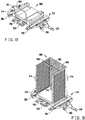
FIG. 8 is a perspective view of an alternate embodiment of the present invention; and -
FIG. 9 is a perspective view of an alternate embodiment of the present invention. - The following detailed description is of the best currently contemplated modes of carrying out exemplary embodiments of the invention. The description is not to be taken in a limiting sense, but is made merely for the purpose of illustrating the general principles of the invention, since the scope of the invention is best defined by the appended claims.
- Broadly, an embodiment of the present invention provides a tugger cart that has a first side, a second side and a locking portion. The first side and second side may include guide wheels aligned in an upward slant. The locking portion may include a rocking arm that is pivotally attached to the tugger cart. The rocking arm may include a lock pedal and an unlock pedal. A rider cart may include a first side and a second side. The first and second side may include wings that are slanted upward, similar to the guide wheels. The rider cart may be pushed onto the tugger cart and the wings may roll along the guide wheels. The rider cart may apply pressure to the lock pedal and the unlock pedal may pivot upward, locking the rider cart onto the tugger cart. To unlock the rider cart, the unlock pedal may be pushed downward, and the rider cart may be removed.
- The present invention may include a loading system that allows a push cart to be loaded on a tugger cart. As the push cart is loaded on the tugger cart the present invention may elevate the push cart using a lift system. For unloading, the operator releases the push cart which slowly rolls off of the tugger cart. The lift functionality allows the push carts to have two swivel casters and two fixed casters which make the carts more controllable than a push cart with four swivel casters.
- The present invention may also eliminate the need to pull the push cart off of the tugger cart which is a very difficult motion.
- In certain embodiments of the present invention, the lift functionality may be achieved by pushing the push cart up a slight incline. The present invention may improve operator control when pushing the push carts and ergonomics of unloading. In certain embodiments, there may be multiple guide wheels with equal spacing in a row on the both sides of the inside of the tugger carts. The first guide wheel may be lower than the last guide wheel making an incline at a slight angle. The push cart may have a metal wing located on both sides positioned at a slight angle. When an operator pushes the push cart on to the tugger cart the metal wings on the push cart roll on top of the rows of guide wheels on the tugger cart and lifts the push cart off of the ground. When the push cart is unlocked from the tugger cart, the wings on the push cart roll on top of the rows of guide wheels on the tugger cart, lowering the cart to ground level as it comes out.
- Referring to
Figures 1 through 9 , the present invention may include atugger cart 10. Thetugger cart 10 may have atugger frame 14. Thetugger frame 14 may include a bottom, a top, afirst side 11, asecond side 13, alocking portion 15, afront end 17, and arear end 19. Thelocking portion 15 may be a middle section in between thefirst side 11 and thesecond side 13. Thefirst side 11, thelocking portion 15, and thesecond side 13 may be joined together at therear end 19 and may form channels in between. Thefirst side 11 and thesecond side 13 may form aninside portion 21 and anoutside portion 23. A plurality ofcasters tugger frame 14. For example, aswivel caster 30 may be attached to the bottom of thefirst side 11 andsecond side 13, and a pair of fixedcasters 32 may be attached to the middle section. A plurality ofvertical guide wheels 34 may be attached to theinside portion 21 of thefirst side 11 and thesecond side 13, or alternatively to the middle section. Thevertical guide wheels 34 may rotate vertically relative to thetugger cart 10. The plurality ofvertical guide wheels 34 may align together to form a slanted line. The slanted line may slant upward from thefront end 17 to therear end 19 of thetugger cart 10. In certain embodiments,anti tip wings 40 may be attached to theinside portion 21 of thefirst side 11 and thesecond side 13. Theanti tip wings 40 may be oriented above the plurality ofvertical guide wheels 34 and may be substantially parallel to the slanted line of the plurality ofvertical guide wheels 34. The present invention may further include at least one firsthorizontal guide wheel 36 near thefront end 17 of thefirst side 11 and thesecond side 13. The present invention may further include at least one secondhorizontal guide wheels 38 attached to the inside portion above theanti tip wings 40. The first and secondhorizontal guide wheels tugger cart 10. - In certain embodiments, the locking portion includes a latch system. The latch system may include at least one rocking
arm 25 pivotally attached to thetugger frame 14 at a pivot point. The at least one rockingarm 25 may include alock pedal 54 near therear end 19 of thetugger frame 14 and anunlock pedal 50 near thefront end 17 of thetugger frame 14. At least one lockingpeg 52 may be attached to the at least one rockingarm 25 and may protrude upwards. Thelock pedal 54 may be biased in an upward position and theunlock pedal 50 may be biased in a downward position. When thelock pedal 54 is forced downward, theunlock pedal 50 and the at least one lockingpeg 52 are forced upward. The at least one lockingpeg 52 may include two locking pegs 52. - In certain embodiments, the at least one rocking
arm 25 may include arear arm 42 pivotally attached to the middle section at afirst pivot point 44, and afront arm 46 pivotally attached to the middle section at asecond pivot point 48. In such embodiments, thelock pedal 54 may be attached to therear arm 42 and theunlock pedal 50 may be attached to thefront arm 46. The at least one lockingpeg 52 may also be attached to thefront arm 46 near theunlock pedal 50. Therear arm 42 and thefront arm 46 may interlock at alock notch 58 and anunlock notch 56, In certain embodiments, thelock pedal 54 of therear arm 42 may be spring biased upwards by arear spring 64 and theunlock pedal 50 of thefront arm 46 may be spring biased upwards by afront spring 66. In such embodiments, when therear arm 42 and thefront arm 46 are interlocked in theunlock notch 56, theunlock pedal 50 and the at least one lockingpeg 54 are forced downward in an unlocked position. Therefore, theunlock pedal 50 is temporarily biased in the downward position due to the force applied by therear arm 42. When pressure is applied to thelock pedal 54, therear arm 42 and thefront arm 46 are shifted and interlocked in thelock notch 58 and theunlock pedal 50 and the at least one lockingpeg 52 are released upward. In certain embodiments, apost pivot pin 60 may connect the lock pedal pegs 52 to thefront arm 46 and may shift within a frontarm pivot slot 62 when the lock pedal pegs 52 are pivoted from the unlocked position to the locked position. - In certain embodiments, the present invention may include a plurality of
tugger carts 10, such as afirst tugger cart 10 and asecond tugger cart 10. Thefirst tugger cart 10 and thesecond tugger cart 10 may be releasably attachable. For example, thetugger cart 10 may include arim 27 protruding from thefirst side 11 and thesecond side 13. Therim 27 may include a top surface. At least one hitchframe attachment post 28 and aball 16 may be attached to the top surface of therim 27. The present invention may further include aframe 20 having a first side and a second side. The second side may be ahitch receiver 18 and the first side may releasably attach to the hitchframe attachment post 28. For example, the second side may include flanges withpeg holes 26 that may fit within a channel of the hitchframe attachment post 28 and align with peg holes 26 formed in the hitchframe attachment post 28. Ahitch receiver peg 22 may be placed within the aligned peg holes 26 and may be secured by a lockingpin 24. To attach the first andsecond tugger carts 10, thefirst tugger cart 10 may include an attachedframe 20 and the hitch receiver of the attachedframe 20 may be coupled with theball 16 of thesecond tugger cart 10. - The present invention may further include a
rider cart 12 formed to be transported on thetugger carts 10. Therider cart 12 may include arider frame 68 having a front end, a rear end, a first side, a second side, a top and a bottom. A plurality ofcasters swivel casters 78 may be attached to the bottom near the rear end and a pair of fixedcasters 76 may be attached to the bottom near the front end. Therider cart 12 may further include afirst rider wing 80 attached to the first side and asecond rider wing 80 attached to the second side. The first andsecond rider wings 80 may be slanted upward from the rear end to the front end. - The
rider cart 12 may include different components for different uses. For example, therider cart 12 may includesidewalls 70 withshelves 72 in between to transport goods. Therider cart 12 may further includehandles 74 to easily push or pull therider cart 12 with ease. In certain embodiments, therider cart 12 of the present invention may include aflatbed rider cart 82 without sidewalls 70 and alarge flatbed handle 84 near the rear. In certain embodiments, therider cart 12 may include apicker cart 88, in which thesidewalls 70 may have swingingdoors 90 attached. In such embodiments, atop spreader 92 may be attached to opposingsidewalls 70. - As illustrated in
Figures 5 through 7 , therider carts 12 may be pushed and locked onto thetugger carts 10. Therider cart 12 may be mounted onto thetugger cart 10 in a locked position and dismounted from thetugger cart 12 in an unlocked position. Therider wings 80 of therider cart 12 may be pushed along thevertical guide wheels 34 until therider cart 12 hits thelock pedal 54. Therider cart frame 68 may apply force against thelock pedal 54. Thelock pedal 54 may pivot alongpivot point 44. Therear arm 42 may lift out of theunlock notch 56 and thefront arm 46 may pivot alongpivot point 48. Thefront arm 46 pivots so that theunlock pedal 50 and thepeg 52 shift upward and thepeg 52 may block therider cart 12 from rolling off of thetugger cart 10 in the locked position. Therear arm 42 may rest within thelock notch 58. To remove therider cart 12 from thetugger cart 10, a user may push down on theunlock pedal 50 downwards so that thepeg 52 is no longer blocking therider cart 12. Therider cart 12 may be removed and therear arm 42 is set back in theunlock notch 56. - It should be understood, of course, that the foregoing relates to exemplary embodiments of the invention and that modifications may be made without departing from the scope of the invention as set forth in the following claims.
Claims (15)
- A tugger cart (10) comprising:a tugger frame (14) comprising a bottom, a top, a first side (11), a second side (13), a locking portion (15), a front end (17) and a rear end (19), wherein the first side (11), the second side (13), and the locking portion (15) are joined together, wherein the first side (11), and the second side (13) form an inside portion (21) in between, and an outside portion (23);a plurality of guide wheels (34) attached within the inside portion (21) of the tugger frame (14), wherein the plurality of guide wheels (34) together form a slanted line slanting upward from the front end (17) to the rear end (19);a plurality of casters (76, 78) attached to the bottom of the tugger frame (14); wherein the locking portion (15) is configured to releasably secure a rider cart (12) to the tugger frame (14) when the rider cart (12) is rolled onto the plurality of guide wheels (34), andwherein the locking portion (15) comprises a latch system comprising at least one rocking arm (25) pivotally attached at a pivot point, wherein the at least one rocking arm (25) comprises a lock pedal (54) near the rear end (19), an unlock pedal (50) near the front end (17), and at least one locking peg (52) protruding upwards from the at least one rocking arm (25), wherein the lock pedal (54) is biased in an upward position and the unlock pedal (50) is biased in a downward position, and wherein when the lock pedal (54) is forced downward the unlock pedal (50) and the at least one locking peg (52) are forced upward.
- The tugger cart (10) of claim 1, wherein the at least one rocking arm (25) comprises a rear arm (42) pivotally attached to the locking portion (15) at a first pivot point (44) and a front arm (46) pivotally attached to the locking portion (15) at a second pivot point (48), wherein the rear arm (42) comprises the lock pedal (54) and the front arm (46) comprises the unlock pedal (50) and the at least one locking peg (52), wherein the rear arm (42) and the front arm (46) interlock at a lock notch (58) and an unlock notch (56).
- The tugger cart (10) of claim 2, wherein the lock pedal (54) of the rear arm (42) is spring biased upwards and the unlock pedal (50) of the front arm (46) is spring biased upwards, wherein when the rear arm (42) and the front arm (46) are interlocked in the unlock notch (56), the unlock pedal (50) and the at least one locking peg (52) are forced downward, wherein when pressure is applied to the lock pedal (54), the rear arm (42) and the front arm (46) are interlocked in the lock notch (58) and the unlock pedal (50) and the at least one locking peg (52) are released upward.
- The tugger cart (10) of claim 3, further comprising a rider cart (12) comprising: a rider frame (68) having a front end, a rear end, a first side, a second side, a top, and a bottom; a plurality of casters (76, 78) attached to the bottom; a first rider wing (80) and a second rider wing (80) attached to the first side and the second side, wherein the first rider wing (80) and the second rider wing (80) are slanted upward from the rear end to the front end.
- The tugger cart (10) of claim 4, wherein the rider cart (12) comprises at least one of shelves (72), sidewalls (70), handles (74), swinging doors (90), and top spreaders (92).
- The tugger cart (10) of claim 4, wherein the plurality of casters (76, 78) comprises a pair of fixed casters (76) attached to the bottom near the front end and a pair of swivel casters (78) attached to the bottom near the rear end.
- The tugger cart (10) of claim 4, wherein the rider cart (12) is mounted onto the tugger cart (10) in a locked position and dismounted from the tugger cart (10) in an unlocked position, wherein the locked position comprises the rider wings (80) rolling onto the vertical guide wheels (34) and the rider frame (68) applying force against the lock pedal (54) and the at least one locking peg (52) protruding upward blocking the rider cart (12) from rolling off of the tugger cart (10), wherein the unlocked position comprises force applied to the unlock pedal (50) forcing the at least one locking peg (52) downwards and thereby allowing rider cart (12) to dismount the tugger cart (10).
- The tugger cart (10) of claim 1, further comprising at least one anti tip wing (40) attached to the inside portion (21) of at least one of the first (11) and second (13) sides, wherein the at least one anti tip wing (40) is oriented above the plurality of guide wheels (34).
- The tugger cart (10) of claim 1, further comprising at least one first horizontal guide wheel (36) near the front end (17) of at least one of the first (11) and second sides (13).
- The tugger cart (10) of claim 9 and 8, further comprising at least one second horizontal guide wheel (38) attached to the inside portion (21) of at least one of the first (11) and second (13) sides above the anti tip wing (40).
- The tugger cart (10) of claim 1, wherein the locking portion (15) includes a middle section between the first side (11) and the second side (13).
- The tugger cart (10) of claim 11, wherein a swivel caster (78) is attached to the first side (11) and the second side (13), and two fixed casters (76) are attached to the locking portion (15).
- A tugger cart apparatus (10), comprising:a plurality of tugger carts (10), comprising at least a first tugger cart (10) and at least a second tugger cart (10), andwherein the first tugger cart (10) and the second tugger cart (10) are releasably attachable, andwherein each of the plurality of tugger carts (10) comprises:a tugger frame (10) comprising a bottom, a top, a first side (11), a second side (13), a locking portion (15), a front end (17) and a rear end (19),wherein the first side (11), the second side (13), and the locking portion (15) are joined together, wherein the first side (11), and the second side (13) form an inside portion (21) in between, and an outside portion (23);a plurality of guide wheels (34) attached within the inside portion (21) of the tugger frame (10), wherein the plurality of guide wheels (34) together form a slanted line slanting upward from the front end (17) to the rear end (19); anda plurality of casters (76, 78) attached to the bottom of the tugger frame (10);wherein the locking portion (15) is configured to releasably secure a rider cart (12) to the tugger frame when the rider cart (12) is rolled onto the plurality of guide wheels (34), andwherein the locking portion (15) comprises a latch system comprising at least one rocking arm (25) pivotally attached at a pivot point, wherein the at least one rocking arm (25) comprises a lock pedal (54) near the rear end (19), an unlock pedal (50) near the front end (17), and at least one locking peg (52) protruding upwards from the at least one rocking arm (25), wherein the lock pedal (54) is biased in an upward position and the unlock pedal (50) is biased in a downward position, and wherein when the lock pedal (54) is forced downward the unlock pedal (50) and the at least one locking peg (52) are forced upward.
- The apparatus (10) of claim 13, wherein the outside portion of the first (11) and second (13) sides of the second tugger cart (10) further comprises a protruding rim (27) with a top surface, wherein the top surface comprises at least one hitch frame attachment post (28) and a ball hitch (16).
- The apparatus (10) of claim 14, wherein the first tugger cart (10) further comprises an attached frame (20) comprising a first side and a second side, wherein the second side comprises a hitch receiver (18) and the first side is releasably attachable to the hitch frame attachment post (28).
Applications Claiming Priority (2)
| Application Number | Priority Date | Filing Date | Title |
|---|---|---|---|
| US14/179,157 US9211900B2 (en) | 2014-02-12 | 2014-02-12 | Tugger and rider cart assembly |
| PCT/US2014/055108 WO2015122933A1 (en) | 2014-02-12 | 2014-09-11 | Tugger and rider cart assembly |
Publications (3)
| Publication Number | Publication Date |
|---|---|
| EP3105104A1 EP3105104A1 (en) | 2016-12-21 |
| EP3105104A4 EP3105104A4 (en) | 2018-03-21 |
| EP3105104B1 true EP3105104B1 (en) | 2019-06-19 |
Family
ID=53774256
Family Applications (1)
| Application Number | Title | Priority Date | Filing Date |
|---|---|---|---|
| EP14882216.6A Not-in-force EP3105104B1 (en) | 2014-02-12 | 2014-09-11 | Tugger and rider cart assembly |
Country Status (5)
| Country | Link |
|---|---|
| US (1) | US9211900B2 (en) |
| EP (1) | EP3105104B1 (en) |
| CN (1) | CN106103237B (en) |
| MX (1) | MX2016010553A (en) |
| WO (1) | WO2015122933A1 (en) |
Families Citing this family (29)
| Publication number | Priority date | Publication date | Assignee | Title |
|---|---|---|---|---|
| CA2893157C (en) | 2014-05-28 | 2023-06-20 | Sailrail Automated Systems Inc. | Industrial cart comprising a mother or primary cart and a secondary or daughter cart |
| US9751547B2 (en) * | 2015-05-12 | 2017-09-05 | Daniel P. Davison, Jr. | Method and apparatus for containment, shipping, and storage of articles |
| US10717598B2 (en) | 2015-05-12 | 2020-07-21 | Daniel P. Davison, Jr. | Method and apparatus for containment, shipping, and storage of articles |
| US10059574B2 (en) * | 2016-05-19 | 2018-08-28 | Gondola Train | Systems and methods for lifting and transporting a shelving system |
| DE102016122683A1 (en) * | 2016-11-24 | 2018-05-24 | Jungheinrich Aktiengesellschaft | Transport trailer with a landing gear and at least one ground platform |
| US10077158B2 (en) * | 2017-01-11 | 2018-09-18 | Toyota Motor Engineering & Manufacturing North America, Inc. | Cargo transport system including motorized pallet |
| US10093334B1 (en) * | 2017-07-24 | 2018-10-09 | Edmund W. Brown | Mother/daughter industrial cart coupling arrangement |
| US10766516B2 (en) * | 2017-09-01 | 2020-09-08 | Cannon Equipment Llc | Modular carts |
| CN108147098A (en) * | 2017-12-28 | 2018-06-12 | 上海君屹工业自动化股份有限公司 | Push suitching type piece uploading platform |
| US11014593B2 (en) * | 2018-04-08 | 2021-05-25 | J-Tec Industries, Inc. | Tugger and rider cart assembly |
| US11285984B2 (en) * | 2018-06-29 | 2022-03-29 | Sailrail Automated Systems, Inc. | Industrial cart comprising a mother or primary cart and a secondary or daughter cart |
| US11130511B2 (en) * | 2018-08-02 | 2021-09-28 | Walmart Apollo, Llc | Light weight pick cart |
| CN109720849A (en) * | 2018-11-08 | 2019-05-07 | 安吉圆磨机械科技有限公司 | Multistation saws automatic lifting material system |
| NL2022608B1 (en) * | 2019-02-21 | 2020-08-31 | Rothar B V | IMPROVED TRANSPORT CAR |
| CN109911059A (en) * | 2019-03-20 | 2019-06-21 | 福建工程学院 | Power induction type follows trolley |
| WO2021046463A1 (en) * | 2019-09-05 | 2021-03-11 | King John Bradford | Vehicle systems and methods |
| DE202019105174U1 (en) * | 2019-09-18 | 2019-10-30 | H + E Produktentwicklung GmbH | Tugger train and tugger train |
| US11820412B2 (en) | 2020-02-07 | 2023-11-21 | Cannon Equipment Llc | Carts with hinges |
| DE102020105370A1 (en) * | 2020-02-28 | 2021-09-02 | Lr Intralogistik Gmbh | Tugger train trailers |
| US11214439B2 (en) | 2020-03-06 | 2022-01-04 | J-Tec Industries, Inc. | Automated tugger cart assembly |
| US11273857B2 (en) * | 2020-03-06 | 2022-03-15 | J-Tec Industries, Inc. | Tugger cart assembly |
| US11655100B2 (en) | 2020-04-06 | 2023-05-23 | Sailrail Automated Systems, Inc. | Cart loader/unloader and a switcher system |
| US12077380B2 (en) | 2020-04-06 | 2024-09-03 | Sailrail Automated Systems, Inc. | Cart loader/unloader and a switcher system and improvements therein |
| JP2022001471A (en) * | 2020-06-22 | 2022-01-06 | Sbs東芝ロジスティクス株式会社 | Traction cart |
| US11554801B2 (en) * | 2020-09-03 | 2023-01-17 | Toyota Motor Engineering & Manufacturing North America, Inc. | Cart apparatuses including cart interlock mechanisms |
| US12017693B2 (en) * | 2021-04-01 | 2024-06-25 | Ralph D. Somheil | Cart device |
| US11904919B2 (en) | 2021-04-06 | 2024-02-20 | Edmund W. Brown | Apparatus and method for assisting in decoupling a wheels-on-ground daughter cart from a mother cart |
| US11787456B2 (en) * | 2021-05-26 | 2023-10-17 | Toyota Motor Engineering & Manufacturing North America, Inc. | Dolly assemblies including locking assemblies for locking child dolly carousels |
| CN115009792B (en) * | 2022-07-25 | 2023-08-25 | 广州城市理工学院 | Drag mechanism |
Family Cites Families (14)
| Publication number | Priority date | Publication date | Assignee | Title |
|---|---|---|---|---|
| US3122244A (en) * | 1962-05-24 | 1964-02-25 | Samuel S Corso | Battery remover and replacer apparatus |
| US4127202A (en) * | 1977-10-31 | 1978-11-28 | Jennings Frederick R | True tracking trailer |
| US5072960A (en) * | 1990-02-15 | 1991-12-17 | Sterilizer Technologies Corporation | Sterilizer cart |
| US6866463B2 (en) * | 2001-11-28 | 2005-03-15 | Ford Motor Company | E-frame and dolly system for stocking production lines |
| DE202008013575U1 (en) * | 2007-09-21 | 2009-01-08 | Hergeth, Willibald | Transport system, in particular with moving pallets |
| DE202009001933U1 (en) | 2009-03-03 | 2009-04-30 | M.W.B. Gmbh | Trailerzuganhänger |
| DE202009008725U1 (en) * | 2009-06-25 | 2009-11-19 | Lts Landtechnik, Transporttechnik Und Stahlbau Gmbh | Transport trolley for lateral acceptance of trolleys |
| PT105301B (en) * | 2010-09-21 | 2013-03-15 | Imeguisa Portugal Ind Metalicas Reunidas S A | TRANSPORT SYSTEM FOR MOBILE PLATFORMS |
| EP2632787B1 (en) * | 2010-10-29 | 2016-05-18 | LKE Gesellschaft für Logistik- und Kommunikations- Equipment mbH | Road train trailer with a carrying device for transporting working vehicle |
| DE102011100145A1 (en) * | 2011-04-29 | 2012-10-31 | Protaurus Produktion + Logistik Gmbh | Trailer for goods wagon used in automotive component production line, has releasable locking unit that is arranged in supporting frame for locking load received in supporting frame |
| FR2979609B1 (en) * | 2011-09-06 | 2014-03-07 | Casino Guichard Perrachon | TRAILER FOR TRANSPORTING A PLURALITY OF TROLLEYS EQUIPPED WITH CASTERS, AND TRANSPORT DEVICE COMPRISING SAID TRAILER |
| DE202012002489U1 (en) * | 2012-03-09 | 2012-05-16 | Stiehle Solutions GmbH | Tugger trailer for ground handling |
| DE202012101625U1 (en) * | 2012-05-03 | 2012-05-21 | Lr Intralogistik Gmbh | Transport unit for internal tugger trains |
| DE202013100729U1 (en) * | 2013-02-19 | 2013-03-11 | Paul Müller Transport- und Verpackungsmittel GmbH | Tugger trailer and system comprising such a tugger trailer and a rollable carrier |
-
2014
- 2014-02-12 US US14/179,157 patent/US9211900B2/en active Active - Reinstated
- 2014-09-11 CN CN201480077363.3A patent/CN106103237B/en not_active Expired - Fee Related
- 2014-09-11 WO PCT/US2014/055108 patent/WO2015122933A1/en active Application Filing
- 2014-09-11 EP EP14882216.6A patent/EP3105104B1/en not_active Not-in-force
- 2014-09-11 MX MX2016010553A patent/MX2016010553A/en active IP Right Grant
Non-Patent Citations (1)
| Title |
|---|
| None * |
Also Published As
| Publication number | Publication date |
|---|---|
| US9211900B2 (en) | 2015-12-15 |
| EP3105104A1 (en) | 2016-12-21 |
| US20150225007A1 (en) | 2015-08-13 |
| MX2016010553A (en) | 2017-05-04 |
| WO2015122933A1 (en) | 2015-08-20 |
| CN106103237B (en) | 2018-11-02 |
| EP3105104A4 (en) | 2018-03-21 |
| CN106103237A (en) | 2016-11-09 |
Similar Documents
| Publication | Publication Date | Title |
|---|---|---|
| EP3105104B1 (en) | Tugger and rider cart assembly | |
| RU2441797C2 (en) | Trolley for transportation and storage of staff | |
| US6386560B2 (en) | Dolly for large appliances | |
| EP2778015B1 (en) | Dolly with slidably retractable tow bar | |
| US8302975B2 (en) | Transport system, in particular having movable pallets | |
| US20180057328A1 (en) | Battery transfer apparatus | |
| US8651500B2 (en) | Dolly transport systems | |
| US6634658B2 (en) | Cart moving system | |
| US20210276603A1 (en) | Tugger cart assembly | |
| US10137838B2 (en) | Cart apparatuses with operable steps | |
| US6102645A (en) | Wheeled cargo transportation cart with dual self-aligning spring action loading ramps | |
| KR101598407B1 (en) | Pallet carrier | |
| US20170355294A1 (en) | Bundle Transport Trailer | |
| EP3585631B1 (en) | Wheeled logistical module provided with a towing device | |
| US6098761A (en) | Locking assembly for wheeled cargo transportation cart | |
| US7506879B1 (en) | Transport cart system incorporating a portable floor surface for unloading palleted containers from a vehicle and method of use | |
| EP0009921A2 (en) | Wheel means for container handling | |
| EP3505419A1 (en) | Mobile platform for transport systems | |
| US9527425B2 (en) | Gravity biased load constraining devices and vehicles incorporating the same | |
| JP3228245U (en) | Connection structure of basket trolley in automatic guided vehicle | |
| WO2005021354A1 (en) | Handling device for transporting loads | |
| GB2563491A (en) | Load handling apparatus | |
| DE102006020646A1 (en) | rollpallet | |
| KR20160079193A (en) | The agricultural carrier which goes to the guide absence and is equipped |
Legal Events
| Date | Code | Title | Description |
|---|---|---|---|
| STAA | Information on the status of an ep patent application or granted ep patent |
Free format text: STATUS: THE INTERNATIONAL PUBLICATION HAS BEEN MADE |
|
| PUAI | Public reference made under article 153(3) epc to a published international application that has entered the european phase |
Free format text: ORIGINAL CODE: 0009012 |
|
| STAA | Information on the status of an ep patent application or granted ep patent |
Free format text: STATUS: REQUEST FOR EXAMINATION WAS MADE |
|
| 17P | Request for examination filed |
Effective date: 20160831 |
|
| AK | Designated contracting states |
Kind code of ref document: A1 Designated state(s): AL AT BE BG CH CY CZ DE DK EE ES FI FR GB GR HR HU IE IS IT LI LT LU LV MC MK MT NL NO PL PT RO RS SE SI SK SM TR |
|
| AX | Request for extension of the european patent |
Extension state: BA ME |
|
| DAX | Request for extension of the european patent (deleted) | ||
| A4 | Supplementary search report drawn up and despatched |
Effective date: 20180221 |
|
| RIC1 | Information provided on ipc code assigned before grant |
Ipc: B62B 3/00 20060101AFI20180215BHEP Ipc: B62D 63/06 20060101ALI20180215BHEP Ipc: B62D 53/00 20060101ALI20180215BHEP Ipc: B62B 5/00 20060101ALI20180215BHEP |
|
| GRAP | Despatch of communication of intention to grant a patent |
Free format text: ORIGINAL CODE: EPIDOSNIGR1 |
|
| STAA | Information on the status of an ep patent application or granted ep patent |
Free format text: STATUS: GRANT OF PATENT IS INTENDED |
|
| RIC1 | Information provided on ipc code assigned before grant |
Ipc: B62D 63/06 20060101ALI20190111BHEP Ipc: B62B 3/00 20060101AFI20190111BHEP Ipc: B62B 5/00 20060101ALI20190111BHEP Ipc: B62D 53/00 20060101ALI20190111BHEP |
|
| INTG | Intention to grant announced |
Effective date: 20190218 |
|
| GRAS | Grant fee paid |
Free format text: ORIGINAL CODE: EPIDOSNIGR3 |
|
| GRAA | (expected) grant |
Free format text: ORIGINAL CODE: 0009210 |
|
| STAA | Information on the status of an ep patent application or granted ep patent |
Free format text: STATUS: THE PATENT HAS BEEN GRANTED |
|
| AK | Designated contracting states |
Kind code of ref document: B1 Designated state(s): AL AT BE BG CH CY CZ DE DK EE ES FI FR GB GR HR HU IE IS IT LI LT LU LV MC MK MT NL NO PL PT RO RS SE SI SK SM TR |
|
| REG | Reference to a national code |
Ref country code: GB Ref legal event code: FG4D |
|
| REG | Reference to a national code |
Ref country code: CH Ref legal event code: EP |
|
| REG | Reference to a national code |
Ref country code: IE Ref legal event code: FG4D |
|
| REG | Reference to a national code |
Ref country code: DE Ref legal event code: R096 Ref document number: 602014048873 Country of ref document: DE |
|
| REG | Reference to a national code |
Ref country code: AT Ref legal event code: REF Ref document number: 1145129 Country of ref document: AT Kind code of ref document: T Effective date: 20190715 |
|
| REG | Reference to a national code |
Ref country code: NL Ref legal event code: MP Effective date: 20190619 |
|
| PG25 | Lapsed in a contracting state [announced via postgrant information from national office to epo] |
Ref country code: FI Free format text: LAPSE BECAUSE OF FAILURE TO SUBMIT A TRANSLATION OF THE DESCRIPTION OR TO PAY THE FEE WITHIN THE PRESCRIBED TIME-LIMIT Effective date: 20190619 Ref country code: LT Free format text: LAPSE BECAUSE OF FAILURE TO SUBMIT A TRANSLATION OF THE DESCRIPTION OR TO PAY THE FEE WITHIN THE PRESCRIBED TIME-LIMIT Effective date: 20190619 Ref country code: SE Free format text: LAPSE BECAUSE OF FAILURE TO SUBMIT A TRANSLATION OF THE DESCRIPTION OR TO PAY THE FEE WITHIN THE PRESCRIBED TIME-LIMIT Effective date: 20190619 Ref country code: NO Free format text: LAPSE BECAUSE OF FAILURE TO SUBMIT A TRANSLATION OF THE DESCRIPTION OR TO PAY THE FEE WITHIN THE PRESCRIBED TIME-LIMIT Effective date: 20190919 Ref country code: HR Free format text: LAPSE BECAUSE OF FAILURE TO SUBMIT A TRANSLATION OF THE DESCRIPTION OR TO PAY THE FEE WITHIN THE PRESCRIBED TIME-LIMIT Effective date: 20190619 Ref country code: AL Free format text: LAPSE BECAUSE OF FAILURE TO SUBMIT A TRANSLATION OF THE DESCRIPTION OR TO PAY THE FEE WITHIN THE PRESCRIBED TIME-LIMIT Effective date: 20190619 |
|
| REG | Reference to a national code |
Ref country code: LT Ref legal event code: MG4D |
|
| PG25 | Lapsed in a contracting state [announced via postgrant information from national office to epo] |
Ref country code: GR Free format text: LAPSE BECAUSE OF FAILURE TO SUBMIT A TRANSLATION OF THE DESCRIPTION OR TO PAY THE FEE WITHIN THE PRESCRIBED TIME-LIMIT Effective date: 20190920 Ref country code: RS Free format text: LAPSE BECAUSE OF FAILURE TO SUBMIT A TRANSLATION OF THE DESCRIPTION OR TO PAY THE FEE WITHIN THE PRESCRIBED TIME-LIMIT Effective date: 20190619 Ref country code: BG Free format text: LAPSE BECAUSE OF FAILURE TO SUBMIT A TRANSLATION OF THE DESCRIPTION OR TO PAY THE FEE WITHIN THE PRESCRIBED TIME-LIMIT Effective date: 20190919 Ref country code: LV Free format text: LAPSE BECAUSE OF FAILURE TO SUBMIT A TRANSLATION OF THE DESCRIPTION OR TO PAY THE FEE WITHIN THE PRESCRIBED TIME-LIMIT Effective date: 20190619 |
|
| REG | Reference to a national code |
Ref country code: AT Ref legal event code: MK05 Ref document number: 1145129 Country of ref document: AT Kind code of ref document: T Effective date: 20190619 |
|
| PG25 | Lapsed in a contracting state [announced via postgrant information from national office to epo] |
Ref country code: PT Free format text: LAPSE BECAUSE OF FAILURE TO SUBMIT A TRANSLATION OF THE DESCRIPTION OR TO PAY THE FEE WITHIN THE PRESCRIBED TIME-LIMIT Effective date: 20191021 Ref country code: EE Free format text: LAPSE BECAUSE OF FAILURE TO SUBMIT A TRANSLATION OF THE DESCRIPTION OR TO PAY THE FEE WITHIN THE PRESCRIBED TIME-LIMIT Effective date: 20190619 Ref country code: SK Free format text: LAPSE BECAUSE OF FAILURE TO SUBMIT A TRANSLATION OF THE DESCRIPTION OR TO PAY THE FEE WITHIN THE PRESCRIBED TIME-LIMIT Effective date: 20190619 Ref country code: AT Free format text: LAPSE BECAUSE OF FAILURE TO SUBMIT A TRANSLATION OF THE DESCRIPTION OR TO PAY THE FEE WITHIN THE PRESCRIBED TIME-LIMIT Effective date: 20190619 Ref country code: NL Free format text: LAPSE BECAUSE OF FAILURE TO SUBMIT A TRANSLATION OF THE DESCRIPTION OR TO PAY THE FEE WITHIN THE PRESCRIBED TIME-LIMIT Effective date: 20190619 Ref country code: RO Free format text: LAPSE BECAUSE OF FAILURE TO SUBMIT A TRANSLATION OF THE DESCRIPTION OR TO PAY THE FEE WITHIN THE PRESCRIBED TIME-LIMIT Effective date: 20190619 Ref country code: CZ Free format text: LAPSE BECAUSE OF FAILURE TO SUBMIT A TRANSLATION OF THE DESCRIPTION OR TO PAY THE FEE WITHIN THE PRESCRIBED TIME-LIMIT Effective date: 20190619 |
|
| PG25 | Lapsed in a contracting state [announced via postgrant information from national office to epo] |
Ref country code: SM Free format text: LAPSE BECAUSE OF FAILURE TO SUBMIT A TRANSLATION OF THE DESCRIPTION OR TO PAY THE FEE WITHIN THE PRESCRIBED TIME-LIMIT Effective date: 20190619 Ref country code: ES Free format text: LAPSE BECAUSE OF FAILURE TO SUBMIT A TRANSLATION OF THE DESCRIPTION OR TO PAY THE FEE WITHIN THE PRESCRIBED TIME-LIMIT Effective date: 20190619 Ref country code: IS Free format text: LAPSE BECAUSE OF FAILURE TO SUBMIT A TRANSLATION OF THE DESCRIPTION OR TO PAY THE FEE WITHIN THE PRESCRIBED TIME-LIMIT Effective date: 20191019 Ref country code: IT Free format text: LAPSE BECAUSE OF FAILURE TO SUBMIT A TRANSLATION OF THE DESCRIPTION OR TO PAY THE FEE WITHIN THE PRESCRIBED TIME-LIMIT Effective date: 20190619 |
|
| PG25 | Lapsed in a contracting state [announced via postgrant information from national office to epo] |
Ref country code: TR Free format text: LAPSE BECAUSE OF FAILURE TO SUBMIT A TRANSLATION OF THE DESCRIPTION OR TO PAY THE FEE WITHIN THE PRESCRIBED TIME-LIMIT Effective date: 20190619 |
|
| PG25 | Lapsed in a contracting state [announced via postgrant information from national office to epo] |
Ref country code: PL Free format text: LAPSE BECAUSE OF FAILURE TO SUBMIT A TRANSLATION OF THE DESCRIPTION OR TO PAY THE FEE WITHIN THE PRESCRIBED TIME-LIMIT Effective date: 20190619 Ref country code: DK Free format text: LAPSE BECAUSE OF FAILURE TO SUBMIT A TRANSLATION OF THE DESCRIPTION OR TO PAY THE FEE WITHIN THE PRESCRIBED TIME-LIMIT Effective date: 20190619 |
|
| PG25 | Lapsed in a contracting state [announced via postgrant information from national office to epo] |
Ref country code: IS Free format text: LAPSE BECAUSE OF FAILURE TO SUBMIT A TRANSLATION OF THE DESCRIPTION OR TO PAY THE FEE WITHIN THE PRESCRIBED TIME-LIMIT Effective date: 20200224 Ref country code: MC Free format text: LAPSE BECAUSE OF FAILURE TO SUBMIT A TRANSLATION OF THE DESCRIPTION OR TO PAY THE FEE WITHIN THE PRESCRIBED TIME-LIMIT Effective date: 20190619 |
|
| REG | Reference to a national code |
Ref country code: CH Ref legal event code: PL |
|
| REG | Reference to a national code |
Ref country code: DE Ref legal event code: R097 Ref document number: 602014048873 Country of ref document: DE |
|
| PLBE | No opposition filed within time limit |
Free format text: ORIGINAL CODE: 0009261 |
|
| STAA | Information on the status of an ep patent application or granted ep patent |
Free format text: STATUS: NO OPPOSITION FILED WITHIN TIME LIMIT |
|
| PG2D | Information on lapse in contracting state deleted |
Ref country code: IS |
|
| PG25 | Lapsed in a contracting state [announced via postgrant information from national office to epo] |
Ref country code: LI Free format text: LAPSE BECAUSE OF NON-PAYMENT OF DUE FEES Effective date: 20190930 Ref country code: IE Free format text: LAPSE BECAUSE OF NON-PAYMENT OF DUE FEES Effective date: 20190911 Ref country code: CH Free format text: LAPSE BECAUSE OF NON-PAYMENT OF DUE FEES Effective date: 20190930 Ref country code: LU Free format text: LAPSE BECAUSE OF NON-PAYMENT OF DUE FEES Effective date: 20190911 |
|
| REG | Reference to a national code |
Ref country code: BE Ref legal event code: MM Effective date: 20190930 |
|
| 26N | No opposition filed |
Effective date: 20200603 |
|
| PG25 | Lapsed in a contracting state [announced via postgrant information from national office to epo] |
Ref country code: SI Free format text: LAPSE BECAUSE OF FAILURE TO SUBMIT A TRANSLATION OF THE DESCRIPTION OR TO PAY THE FEE WITHIN THE PRESCRIBED TIME-LIMIT Effective date: 20190619 Ref country code: BE Free format text: LAPSE BECAUSE OF NON-PAYMENT OF DUE FEES Effective date: 20190930 |
|
| GBPC | Gb: european patent ceased through non-payment of renewal fee |
Effective date: 20190919 |
|
| PG25 | Lapsed in a contracting state [announced via postgrant information from national office to epo] |
Ref country code: FR Free format text: LAPSE BECAUSE OF NON-PAYMENT OF DUE FEES Effective date: 20190930 Ref country code: GB Free format text: LAPSE BECAUSE OF NON-PAYMENT OF DUE FEES Effective date: 20190919 |
|
| PG25 | Lapsed in a contracting state [announced via postgrant information from national office to epo] |
Ref country code: CY Free format text: LAPSE BECAUSE OF FAILURE TO SUBMIT A TRANSLATION OF THE DESCRIPTION OR TO PAY THE FEE WITHIN THE PRESCRIBED TIME-LIMIT Effective date: 20190619 |
|
| PG25 | Lapsed in a contracting state [announced via postgrant information from national office to epo] |
Ref country code: HU Free format text: LAPSE BECAUSE OF FAILURE TO SUBMIT A TRANSLATION OF THE DESCRIPTION OR TO PAY THE FEE WITHIN THE PRESCRIBED TIME-LIMIT; INVALID AB INITIO Effective date: 20140911 Ref country code: MT Free format text: LAPSE BECAUSE OF FAILURE TO SUBMIT A TRANSLATION OF THE DESCRIPTION OR TO PAY THE FEE WITHIN THE PRESCRIBED TIME-LIMIT Effective date: 20190619 |
|
| PGFP | Annual fee paid to national office [announced via postgrant information from national office to epo] |
Ref country code: DE Payment date: 20210406 Year of fee payment: 8 |
|
| PG25 | Lapsed in a contracting state [announced via postgrant information from national office to epo] |
Ref country code: MK Free format text: LAPSE BECAUSE OF FAILURE TO SUBMIT A TRANSLATION OF THE DESCRIPTION OR TO PAY THE FEE WITHIN THE PRESCRIBED TIME-LIMIT Effective date: 20190619 |
|
| REG | Reference to a national code |
Ref country code: DE Ref legal event code: R119 Ref document number: 602014048873 Country of ref document: DE |
|
| PG25 | Lapsed in a contracting state [announced via postgrant information from national office to epo] |
Ref country code: DE Free format text: LAPSE BECAUSE OF NON-PAYMENT OF DUE FEES Effective date: 20230401 |