EP3104470A1 - Socket assembly with multiple flush-mounting boxes - Google Patents
Socket assembly with multiple flush-mounting boxes Download PDFInfo
- Publication number
- EP3104470A1 EP3104470A1 EP16173851.3A EP16173851A EP3104470A1 EP 3104470 A1 EP3104470 A1 EP 3104470A1 EP 16173851 A EP16173851 A EP 16173851A EP 3104470 A1 EP3104470 A1 EP 3104470A1
- Authority
- EP
- European Patent Office
- Prior art keywords
- base
- bridge part
- sidewall
- flush
- socket
- Prior art date
- Legal status (The legal status is an assumption and is not a legal conclusion. Google has not performed a legal analysis and makes no representation as to the accuracy of the status listed.)
- Granted
Links
Images


Classifications
-
- H—ELECTRICITY
- H01—ELECTRIC ELEMENTS
- H01R—ELECTRICALLY-CONDUCTIVE CONNECTIONS; STRUCTURAL ASSOCIATIONS OF A PLURALITY OF MUTUALLY-INSULATED ELECTRICAL CONNECTING ELEMENTS; COUPLING DEVICES; CURRENT COLLECTORS
- H01R24/00—Two-part coupling devices, or either of their cooperating parts, characterised by their overall structure
- H01R24/76—Two-part coupling devices, or either of their cooperating parts, characterised by their overall structure with sockets, clips or analogous contacts and secured to apparatus or structure, e.g. to a wall
- H01R24/78—Two-part coupling devices, or either of their cooperating parts, characterised by their overall structure with sockets, clips or analogous contacts and secured to apparatus or structure, e.g. to a wall with additional earth or shield contacts
-
- H—ELECTRICITY
- H01—ELECTRIC ELEMENTS
- H01R—ELECTRICALLY-CONDUCTIVE CONNECTIONS; STRUCTURAL ASSOCIATIONS OF A PLURALITY OF MUTUALLY-INSULATED ELECTRICAL CONNECTING ELEMENTS; COUPLING DEVICES; CURRENT COLLECTORS
- H01R25/00—Coupling parts adapted for simultaneous co-operation with two or more identical counterparts, e.g. for distributing energy to two or more circuits
- H01R25/006—Coupling parts adapted for simultaneous co-operation with two or more identical counterparts, e.g. for distributing energy to two or more circuits the coupling part being secured to apparatus or structure, e.g. duplex wall receptacle
-
- H—ELECTRICITY
- H01—ELECTRIC ELEMENTS
- H01R—ELECTRICALLY-CONDUCTIVE CONNECTIONS; STRUCTURAL ASSOCIATIONS OF A PLURALITY OF MUTUALLY-INSULATED ELECTRICAL CONNECTING ELEMENTS; COUPLING DEVICES; CURRENT COLLECTORS
- H01R9/00—Structural associations of a plurality of mutually-insulated electrical connecting elements, e.g. terminal strips or terminal blocks; Terminals or binding posts mounted upon a base or in a case; Bases therefor
- H01R9/22—Bases, e.g. strip, block, panel
- H01R9/24—Terminal blocks
- H01R9/2458—Electrical interconnections between terminal blocks
-
- H—ELECTRICITY
- H02—GENERATION; CONVERSION OR DISTRIBUTION OF ELECTRIC POWER
- H02G—INSTALLATION OF ELECTRIC CABLES OR LINES, OR OF COMBINED OPTICAL AND ELECTRIC CABLES OR LINES
- H02G3/00—Installations of electric cables or lines or protective tubing therefor in or on buildings, equivalent structures or vehicles
- H02G3/02—Details
- H02G3/08—Distribution boxes; Connection or junction boxes
- H02G3/086—Assembled boxes
-
- H—ELECTRICITY
- H01—ELECTRIC ELEMENTS
- H01R—ELECTRICALLY-CONDUCTIVE CONNECTIONS; STRUCTURAL ASSOCIATIONS OF A PLURALITY OF MUTUALLY-INSULATED ELECTRICAL CONNECTING ELEMENTS; COUPLING DEVICES; CURRENT COLLECTORS
- H01R13/00—Details of coupling devices of the kinds covered by groups H01R12/70 or H01R24/00 - H01R33/00
- H01R13/73—Means for mounting coupling parts to apparatus or structures, e.g. to a wall
-
- H—ELECTRICITY
- H01—ELECTRIC ELEMENTS
- H01R—ELECTRICALLY-CONDUCTIVE CONNECTIONS; STRUCTURAL ASSOCIATIONS OF A PLURALITY OF MUTUALLY-INSULATED ELECTRICAL CONNECTING ELEMENTS; COUPLING DEVICES; CURRENT COLLECTORS
- H01R2103/00—Two poles
-
- H—ELECTRICITY
- H01—ELECTRIC ELEMENTS
- H01R—ELECTRICALLY-CONDUCTIVE CONNECTIONS; STRUCTURAL ASSOCIATIONS OF A PLURALITY OF MUTUALLY-INSULATED ELECTRICAL CONNECTING ELEMENTS; COUPLING DEVICES; CURRENT COLLECTORS
- H01R31/00—Coupling parts supported only by co-operation with counterpart
- H01R31/02—Intermediate parts for distributing energy to two or more circuits in parallel, e.g. splitter
-
- H—ELECTRICITY
- H02—GENERATION; CONVERSION OR DISTRIBUTION OF ELECTRIC POWER
- H02G—INSTALLATION OF ELECTRIC CABLES OR LINES, OR OF COMBINED OPTICAL AND ELECTRIC CABLES OR LINES
- H02G3/00—Installations of electric cables or lines or protective tubing therefor in or on buildings, equivalent structures or vehicles
- H02G3/02—Details
- H02G3/08—Distribution boxes; Connection or junction boxes
- H02G3/16—Distribution boxes; Connection or junction boxes structurally associated with support for line-connecting terminals within the box
Landscapes
- Engineering & Computer Science (AREA)
- Architecture (AREA)
- Civil Engineering (AREA)
- Structural Engineering (AREA)
- Connector Housings Or Holding Contact Members (AREA)
Abstract
Description
- The present invention relates to a socket assembly with multiple flush-mounting boxes for flush-mounted installation in a wall, the socket assembly being configured for the provision of power to multiple electrical loads.
- As known by a person skilled in the art, a socket assembly usually comprises a base and a cover. The base is provided with the electrical socket function, i.e. a socket outlet. The cover typically comprises a central member, which is often also referred to as central plate or finishing set, and a cover frame, which may also be referred to as flush surround plate and which extends around the central member. The base is mounted in a flush-mounting box and connected to electrical wires in the wall.
- When multiple sockets need to be provided, it is common to arrange a plurality of flush-mounting boxes next to each other in a wall. Optionally, the flush-mounting boxes may be attached to each other before arranging the attached boxes into the wall. The base with socket function is typically mounted in a mounting box using a screw or claw connection. In some countries, the claw connection is preferred as it has more degrees of freedom when having to level the base in the mounting box. The claw grips onto an inner sidewall of the flush-mounting box. In other words, when a first and second mounting box are arranged next to each other, a first claw grips onto a first sidewall of the first mounting box and a second claw grips onto a second sidewall of the second mounting box, said second sidewall being adjacent the first sidewall. These first and second sidewalls create a wall barrier between the interior of the first and second mounting box. Any electrical wires to be connected to the first and second base need to pass through holes in the sidewalls of the flush-mounting boxes.
- It is an object of embodiments of the present invention to provide a socket assembly with multiple flush-mounting boxes for flush-mounted installation in a wall, which allows for an improved mounting and wiring of the socket bases in the respective socket mounting boxes.
- In a first aspect, the present invention provides a socket assembly for flush-mounted installation in a wall. The socket assembly comprises a first flush-mounting box having a first sidewall and a second flush-mounting box having a second sidewall, the first and second sidewall being intended for being arranged adjacent to each other in the wall. The socket assembly further comprises a first base and a second base, each comprising a socket function and a first fixation means and a second fixation means for respectively fixing the first and second base in respectively the first and second flush-mounting box. According to the present invention, the socket assembly furthermore comprises a bridge part configured for extending across the first and second sidewall inside the interior of the first and second flush-mounting box and behind the first and second base, the bridge part comprising electrically conductive paths electrically connecting the socket function of the first base to the socket function of the second base.
- By using a bridge part that connects the socket function of the first base and the socket function of the second base, the mounting of the first and second bases in the respective first and second flush-mounting boxes is significantly simplified with respect to prior art socket assemblies. With a socket assembly according to embodiments of the invention, it is avoided that wires for connecting the first and second socket function have to pass through the side walls of the flush-mounting boxes. Further, a socket assembly with a bridge part according to embodiments of the invention will not hinder the use of the fixation means for fixing the first and second base in respectively the first and second flush-mounting box. By having a bridge part which extends behind the first and second base, the connection between the electrically conductive parts and the socket functions can be easily realized.
- According to embodiments of the invention, the electrically conductive paths may have first connection parts and second connection parts connectable to the socket function of respectively the first and second base. The first and second connection parts may, according to embodiments of the invention, be elongate flexible or bendable parts such that they can be manipulated and inserted in a hole in respectively the first and second base. The first and second connection parts may be provided at respectively a first and second upper edge of the bridge part. Positioning the first and second connection parts at an upper edge will allow for conveniently connecting the electrically conductive paths to the socket functions, because the socket functions typically comprise holes in an upper part thereof.
- The bridge part may, according to embodiments of the invention, comprise at least a first and a second fold line extending parallel to an upper edge of the first and second sidewall, such that a first panel of the bridge part can be folded against the inner side of the first sidewall and a second panel of the bridge part can be folded against the inner side of the second sidewall. Such fold lines will allow for an easy arrangement of the bridge part in the flush-mounting boxes. According to further embodiments, the bridge part may comprise a third and a fourth fold line extending parallel to the upper edge of the first and second sidewall, the third fold line extending between the first fold line and a first outer edge of the bridge part, and the fourth fold line extending between the second fold line and a second outer edge of the bridge part. In that way, the outer edges of the bridge part can easily be arranged behind the first and second socket function.
- According to embodiments of the invention, the bridge part may comprise a flexible member, such that the flexible member can extend from an inner side of the first sidewall to an inner side of the second sidewall. According to further embodiments of the invention, further flexible members may be provided for allowing parts of the bridge part to extend behind the first and second socket function.
- The bridge part may be configured to allow a portion of the first and second fixation means to extend through or adjacent the bridge part to grip onto respectively the first and second sidewall. According to embodiments of the invention, the first and second fixation means may each comprise at least two claws, and the bridge part may then be adapted, e.g. by having suitable recesses to allow a claw to extend through the bridge part. According to other embodiments of the invention, the fixation means may be screws which fix a frame of the base to the flush-mounting box. According to such embodiments, the bridge part does not need to be provided with recesses. The bridge part may, according to embodiments of the invention, comprise a printed circuit board (PCB), for example a multilayer PCB. The PCB may be a flexible PCB or a PCB provided with a number of fold lines. In that way, the conductive paths can easily be arranged.
- According to embodiments of the invention, the first and second base may respectively comprise a first and a second frame, the first and second frame being configured to extend in front of the first and second socket function, respectively, wherein the first and second frame are configured to be attached to the bridge part.
- According to embodiments of the invention, the second flush-mounting box may have a third sidewall opposite the second sidewall and the socket assembly may further comprise a third flush-mounting box. The third flush-mounting box may comprise a fourth sidewall intended for being arranged adjacent to the third sidewall in the wall; a third base comprising a socket function and a third fixation means for fixing the third base in the third flush-mounting box. According to these embodiments, the bridge part may further be configured for extending across said third and fourth sidewall inside the interior of the third flush-mounting box behind the third base, whereby the electrically conductive paths of the bridge part are also connectable to the socket function of the third base.
- The socket assembly may further comprise a first and second central member each comprising at least two through-holes in which at least two pins of a plug are insertable for being electrically connected to the socket function of respectively the first and second base, the first and second central member being intended for being attached to respectively the first and second base. According to specific embodiments, the first and second central member may be made of a plastic material and/or the first and second base may each comprise a metal frame configured for fixing the base in the opening in the wall.
- According to embodiments of the invention, the socket assembly may further comprise a first and a second cover frame configured for respectively surrounding the first and second central member. According to a second aspect of the invention, a bridge part is provided for use in a socket assembly according embodiments of the invention. The bridge part is configured for extending across a first and second sidewall of a first and second flush-mounting box, inside the interior of the first and second flush-mounting box and behind a first and second base. The bridge part comprises electrically conductive paths connectable to the socket function of the first and second base, respectively.
- The bridge part may have properties as described in the embodiments above.
- According to a further aspect, the invention provides a method for installing a plurality of socket functions in a wall. The method comprises:
- arranging a plurality of flush-mounting boxes adjacent to each other in the wall;
- selecting a bridge part configured for extending across adjacent wall parts of the plurality of flush-mounting boxes and behind a corresponding plurality of bases intended for being arranged in the plurality of flush-mounting boxes; the plurality of bases comprising the plurality of socket functions; the bridge part being provided with electrically conductive paths for electrically connecting the plurality of socket functions;
- connecting the plurality of socket functions to the electrically conductive paths;
- arranging the bridge part with the plurality of bases in the plurality of flush-mounting boxes; and fixing the plurality of bases in the plurality of flush-mounting boxes.
- Selecting of a bridge part may comprise cutting a strip with electrically conductive paths to size in function of the plurality of socket functions to be connected.
- It has to be noted that same reference signs in the different figures refer to same, similar or analogous elements.
-
Figure 1 illustrates an exploded perspective view looking from the front to the back of a socket assembly according to embodiments of the invention; -
Figure 2 illustrates a perspective view looking from the front to the back of the socket assembly of the invention ofFig. 1 , in an assembled state; -
Figure 3 is a schematic view of a bridge part according to a first embodiment of the invention; -
Figure 4 is a schematic view of a bridge part according to a second embodiment of the invention; -
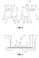
Figure 5 is a schematic top view of a socket assembly according to further embodiments of the invention; -
Figure 6 is an exploded perspective view looking from the front to the back of a a socket assembly according to embodiments of the invention. - In the description different embodiments will be used to describe the invention. Therefore reference will be made to different drawings. It has to be understood that these drawings are intended to be non-limiting, the invention is only limited by the claims. The drawings are thus for illustrative purposes, the size of some of the elements in the drawings may be exaggerated for clarity purposes.
- The term "comprising" is not to be interpreted as limiting the invention in any way. The term "comprising", used in the claims, is not intended to be restricted to what means is described thereafter; it does not exclude other elements, parts or steps.
- The term "connected" as used in the claims and in the description has not to be interpreted as being restricted to direct connections, unless otherwise specified. Thus, part A being connected to part B is not limited to part A being in direct contact to part B, but also includes indirect contact between part A and part B, in other words also includes the case where intermediate parts are present in between part A and part B.
- In the context of the present invention, the term "socket assembly" refers to an assembly suitable for placement in a fixed location in the building and configured for facilitating the provision of power to a load in the wall. Typically, the assembly is intended and configured for being mounted at least partially in an opening in the wall where the socket function of the first base is connected to electrical wires present in the wall. Typically, the electrical wires in the wall comprise wires connected to the mains. However, in other embodiments, the electrical wires in the wall may comprise wires connected to a DC power source. More generally, the wires in the wall may be connected to any AC or DC power source.
- Not all embodiments of the invention comprise all features of the invention. In the following description and claims, any of the claimed embodiments can be used in any combination.
- The present invention provides a socket assembly for flush-mounted installation in a wall. The socket assembly comprises a first flush-mounting box having a first sidewall and a second flush-mounting box having a second sidewall, the first and second sidewall being intended for being arranged adjacent to each other in the wall. The socket assembly further comprises a first base and a second base, each comprising a socket function; and a first fixation means and a second fixation means for respectively fixing the first and second base in respectively the first and second flush-mounting box. According to the invention, the socket assembly furthermore comprises a bridge part configured for extending across the first and second sidewall inside the interior of the first and second flush-mounting box and behind the first and second base, the bridge part comprising electrically conductive paths electrically connecting the socket function of the first base to the socket function of the second base.
- By using a bridge part that connects the socket function of the first base and the socket function of the second base, the mounting of the first and second bases in the respective first and second flush-mounting boxes is significantly simplified with respect to prior art socket assemblies. With a socket assembly according to embodiments of the invention, it is avoided that wires for connecting the first and second socket function have to pass through the side walls of the flush-mounting boxes. Further, a socket assembly with a bridge part according to embodiments of the invention will not hinder the use of the fixation means for fixing the first and second base in respectively the first and second flush-mounting box. By having a bridge part which extends behind the first and second base, the connection between the electrically conductive parts and the socket functions can be easily realized.
- The present invention will hereinafter be described by means of different embodiments. It has to be understood that these embodiments are only for the ease of understanding the invention and are not intended to limit the invention in any way.
-
Figures 1 and 2 illustrate asocket assembly 100 for flush-mounted installation in a wall according to a first embodiment of the invention. Thesocket assembly 100 comprises a first and a second flush-mountingbox second sidewall boxes second sidewall socket assembly 100 further comprises a first andsecond base socket function socket assembly 100 furthermore comprises a first fixation means 121 and a second fixation means 221 for respectively fixing the first andsecond base box Figure 1 , the first andsecond base box claws 121 and a second set ofclaws 221. Theclaws base base box - The
socket assembly 100 further comprises abridge part 300 configured for extending from inside the interior of the first flush-mountingbox 110 to interior of the second flush-mountingbox 210 across the first and second sidewall 111,211 and behind the first andsecond base bridge part 300 comprises electrically conductive paths (not shown infigure 1 , but may be integrated in thebridge part 300 as shown infigure 4 , seereference numerals socket function 124 of thefirst base 120 to thesocket function 224 of thesecond base 220. The electricallyconductive paths first connection parts second connection parts socket function second base second base second connection parts base second connection parts upper edge bridge part 300, respectively, such that they can be easily inserted in theholes - Typically the
connection parts suitable holes standard holes second connection parts bridge part 300 to the socket functions 124, 224. According to a preferred embodiment, for eachsocket assembly 100 threeconductive paths connection parts socket function - According to embodiments of the invention, the first and
second connection parts connection parts hole second base - As can be seen from
figures 1 and3 , thebridge part 300 may comprise a first and asecond fold line upper edge second sidewall first panel 361 of thebridge part 300 can be folded against the inner side of thefirst sidewall 111 and asecond panel 362 of thebridge part 300 can be folded against the inner side of thesecond sidewall 211. Acentral panel 360 is located between the first andsecond fold line front edges 113, 213 of the first andsecond sidewall boxes bridge part 300 further comprises a third and afourth fold line upper edge second sidewall third fold line 353 is located between thefirst fold line 351 and a firstouter edge 301 of thebridge part 300, and thefourth fold line 354 is located between thesecond fold line 352 and a secondouter edge 302 of thebridge part 300. Through the third andfourth fold lines outer panels bridge part 300 can be folded respectively behind the first andsecond base - According to other embodiments of the invention, the
bridge part 300 may consist of or may comprise a flexible member, e.g. a flexible PCB, such that the flexible member can extend from an inner side of thefirst sidewall 111 to an inner side of thesecond sidewall 112. Such an embodiment is schematically illustrated infigure 4 . According to such embodiments, and similar to thebridge part 300 illustrated infigures 1 to 3 , thebridge part 300 may be configured to extend behind the first andsecond base - Preferably the
bridge part 300 may be configured to allow a portion of the first and second fixation means 121, 221, e.g. claws, to extend through or adjacent thebridge part 300 to grip onto respectively the first andsecond sidewall bridge part 300 according to the embodiment offigure 3 , to that end, tworecesses bridge part 300 according to the embodiment offigure 4 , the shape of thebridge part 300 is such that the first and second fixation means 121, 221, e.g. claws, extend adjacent to thebridge part 300. - According to embodiments of the invention, the
bridge part 300 may comprise a PCB, e.g. a multilayer PCB. Preferably thebridge part 300 comprises the electrical paths between a substrate and a coating or top layer. Preferably thebridge part 300 may have a thickness which is lower than 4 mm, preferably lower than 2,5 mm. - According to embodiments of the invention, the first and
second base second frame second frame second frame second socket function bridge part 300, seereference numerals figure 5 . In that way, thebridge part 300 may be attached to the frame, whereupon the first andsecond base bridge part 300 may be inserted as a unit in the first and second flush-mountingboxes - The
socket assembly 100 may furthermore comprise a first and secondcentral member holes socket function second base central member second base central member - The
socket assembly 100 may further comprise one or more cover frames (not shown) configured for surrounding the first and secondcentral member - The
socket assembly 100 controls the provision of power to electrical appliances via plugs inserted in the socket outlet. Thesocket assembly 100 is intended to be built-in in an opening in the wall, where thesocket function 124 of thefirst base 120 is connected toelectrical wires cable 400 present in the wall, seefigure 5 . Typically, theelectrical wires - It has to be noted that the concept of the invention also can be extended to an assembly with more than two flush-mounting boxes, wherein the
bridge part 300 extends throughout adjacent flush-mounting boxes, from the backside of afirst socket function 124 in a first flush-mountingbox 110, overadjacent sidewalls box second socket function 224 in a second flush-mountingbox 210, over adjacent sidewalls 213, 211' of the second and a third flush-mountingbox 210, 210', to the backside of the third socket function 224' in a third flush-mounting box 210'.Figure 6 illustrates a further embodiment of asocket assembly 100 for flush-mounted installation in a wall according to the invention. Thesocket assembly 100 may comprise a first, a second, and a third flush-mountingbox socket assembly 100 may further comprise a first, a second, and athird base socket function third base boxes - The
bridge part 300 according to the present embodiments may be similar to the bridge part offigure 1 with this difference that it comprises two "bridges" for extending across the first and second wall barrier. - A person skilled in the art may understand that the
bridge part 300 may be used to connect even more than three flush-mountingboxes bridge part 300 may be provided as a long strip with electrically conductive paths and a plurality of sets of connection parts, wherein the strip may be cut to size by an electrician in function of the number of flush-mountingboxes - Whilst the principles of the invention have been set out above in connection with specific embodiments, it is to be understood that this description is merely made by way of example and not as a limitation of the scope of protection which is determined by the appended claims.
Claims (15)
- A socket assembly (100) for flush-mounted installation in a wall; the socket assembly (100) comprising:- a first flush-mounting box (110) having a first sidewall (111) and a second flush-mounting box (210) having a second sidewall (211), the first and second sidewall (111, 211) being intended for being arranged adjacent to each other in the wall;- a first base (120) and a second base (220), each comprising a socket function (124, 224);- a first fixation means (121) and a second fixation means (221) for respectively fixing the first and second base (120, 220) in respectively the first and second flush-mounting box (110, 210);- a bridge part (300) configured for extending across the first and second sidewall (111,211) inside the interior of the first and second flush-mounting box (110, 210) and behind the first and second base (120, 220), the bridge part (300) comprising electrically conductive paths (311, 312, 313) electrically connecting the socket function (124) of the first base (120) to the socket function (224) of the second base (220).
- A socket assembly (100) according to claim 1, wherein the electrically conductive paths (311, 312, 313) have first connection parts (321, 322, 323) and second connection parts (331, 332, 333) connectable to the socket function (124, 224) of respectively the first and second base (120, 220).
- A socket assembly (100) according to claim 2, wherein the first and second connection parts (321, 322, 323, 331, 332, 333) are elongate flexible or bendable parts such that they can be manipulated and inserted in a hole (122, 222) in respectively the first and second base (120, 220).
- A socket assembly (100) according to claim 2 or 3, wherein the first and second connection parts (321, 322, 323, 331, 332, 333) are provided at respectively a first and second upper edge (371, 372) of the bridge part (300).
- A socket assembly (100) according to any of the previous claims, wherein the bridge part (300) comprises at least a first and a second fold line (351, 352) extending parallel to an upper edge (112, 212) of the first and second sidewall (111, 211), such that a first panel (361) of the bridge part (300) can be folded against the inner side of the first sidewall (111) and a second panel (362) of the bridge part (300) can be folded against the inner side of the second sidewall (211).
- A socket assembly (100) according to claim 5, wherein the bridge part (300) comprises a third and a fourth fold line (353, 354) extending parallel to an upper edge (112, 212) of the first and second sidewall (111, 211), the third fold line (353) extending between the first fold line (351) and a first outer edge (301) of the bridge part (300), and the fourth fold line (354) extending between the second fold line (352) and a second outer edge (302) of the bridge part (300).
- A socket assembly (100) according to any of the claims 1 to 4, wherein the bridge part (300) comprises a flexible member, such that the flexible member can extend from an inner side of the first sidewall (111) to an inner side of the second sidewall (121).
- A socket assembly (100) according to any of the previous claims, wherein the bridge part (300) is configured to allow a portion of the first and second fixation means (121, 221) to extend through or adjacent the bridge part (300) to grip onto respectively the first and second sidewall (111, 112).
- A socket assembly (100) according to any of the previous claims, wherein the bridge part (300) comprises a PCB.
- A socket assembly (100) according to any of the previous claims, wherein the first and second connections parts (321, 322, 323, 331, 332, 333) each comprise at least two claws.
- A socket assembly (100) according to any of the previous claims, wherein the first and second base (120, 220) respectively comprise a first and a second frame (125, 225), the first and second frame (125, 225) being configured to extend in front of the first and second socket function (124, 224), respectively, wherein the first and second frame (125, 225) are configured to be attached to the bridge part (300).
- A socket assembly (100) according to any of the previous claims, wherein the second flush-mounting box (210) has a third sidewall (213) opposite the second sidewall (211) and wherein the socket assembly (100) further comprises a third flush-mounting box (210') comprising:- a fourth sidewall (211') intended for being arranged adjacent to the third sidewall (213) in the wall;- a third base (220') comprising a socket function (224'); and- a third fixation means (221') for fixing the third base (220') in the third flush-mounting box (210');
and wherein the bridge part (300) is further configured for extending across said third and fourth sidewall (213, 211') inside the interior of the third flush-mounting box (210') and behind the third base (221'), wherein the electrically conductive paths (311, 312, 313) of the bridge part (300) are also connectable to the socket function (224') of the third base (220'). - A socket assembly (100) according to any of the previous claims, further comprising a first and second central member (130, 230) each comprising at least two through-holes (126, 226) in which at least two pins of a plug are insertable for being electrically connected to the socket function (124, 224) of respectively the first and second base (120, 220); the first and second central member (130, 230) being intended for being attached to respectively the first and second base (120, 220).
- A socket assembly (100) according to claim 13, wherein the first and second central member (130, 230) are made of a plastic material and/or wherein the first and second base (120, 220) each comprise a metal frame configured for fixing the base (120, 220) in the opening in the wall.
- A socket assembly (100) according to claim 13 or 14, further comprising a first and a second cover frame configured for respectively surrounding the first and second central member (130, 230).
Priority Applications (1)
| Application Number | Priority Date | Filing Date | Title |
|---|---|---|---|
| PL16173851T PL3104470T3 (en) | 2015-06-12 | 2016-06-10 | Socket assembly with multiple flush-mounting boxes |
Applications Claiming Priority (1)
| Application Number | Priority Date | Filing Date | Title |
|---|---|---|---|
| BE20150166A BE1023178A1 (en) | 2015-06-12 | 2015-06-12 | SOCKET COMPOSITION WITH MULTIPLE RECESSED BOXES |
Publications (2)
| Publication Number | Publication Date |
|---|---|
| EP3104470A1 true EP3104470A1 (en) | 2016-12-14 |
| EP3104470B1 EP3104470B1 (en) | 2018-08-15 |
Family
ID=54199497
Family Applications (1)
| Application Number | Title | Priority Date | Filing Date |
|---|---|---|---|
| EP16173851.3A Active EP3104470B1 (en) | 2015-06-12 | 2016-06-10 | Socket assembly with multiple flush-mounting boxes |
Country Status (4)
| Country | Link |
|---|---|
| EP (1) | EP3104470B1 (en) |
| BE (1) | BE1023178A1 (en) |
| DK (1) | DK3104470T3 (en) |
| PL (1) | PL3104470T3 (en) |
Cited By (4)
| Publication number | Priority date | Publication date | Assignee | Title |
|---|---|---|---|---|
| EP3767766A1 (en) * | 2019-07-16 | 2021-01-20 | Niko NV | Electric or electronic device |
| BE1027439B1 (en) * | 2019-07-16 | 2021-02-16 | Niko Nv | ELECTRICAL OR ELECTRONIC DEVICE |
| IT201900025705A1 (en) * | 2019-12-30 | 2021-06-30 | Bticino Spa | Connection module and modular group for electrical and / or home automation systems |
| IT201900025693A1 (en) * | 2019-12-30 | 2021-06-30 | Bticino Spa | Cover plate for electrical and / or home automation systems |
Citations (4)
| Publication number | Priority date | Publication date | Assignee | Title |
|---|---|---|---|---|
| US4375307A (en) * | 1981-03-30 | 1983-03-01 | General Electric Company | Grounding receptacle with low resistance ground |
| US5484309A (en) * | 1994-10-31 | 1996-01-16 | Hubbell Incorporated | Electrical receptacle assembly with interference fitting and latching parts |
| DE10121231A1 (en) * | 2001-04-25 | 2001-11-08 | Fritz Klapproth | Socket outlet expandable to form socket outlet connector for wall-mounted electrical items e.g. light switch or dimmer, includes adapter as upper part for receiving plug and base as releasably connected bottom part for receiving conductor |
| DE102012107623A1 (en) * | 2011-08-24 | 2013-02-28 | Legrand France | Connector block for electrically connecting e.g. device mechanisms of multi-apparatus block, has electrical conductors insulated from each other and protruding from protective sheath over major sides, which are fixed perpendicular to ends |
-
2015
- 2015-06-12 BE BE20150166A patent/BE1023178A1/en not_active IP Right Cessation
-
2016
- 2016-06-10 DK DK16173851.3T patent/DK3104470T3/en active
- 2016-06-10 EP EP16173851.3A patent/EP3104470B1/en active Active
- 2016-06-10 PL PL16173851T patent/PL3104470T3/en unknown
Patent Citations (4)
| Publication number | Priority date | Publication date | Assignee | Title |
|---|---|---|---|---|
| US4375307A (en) * | 1981-03-30 | 1983-03-01 | General Electric Company | Grounding receptacle with low resistance ground |
| US5484309A (en) * | 1994-10-31 | 1996-01-16 | Hubbell Incorporated | Electrical receptacle assembly with interference fitting and latching parts |
| DE10121231A1 (en) * | 2001-04-25 | 2001-11-08 | Fritz Klapproth | Socket outlet expandable to form socket outlet connector for wall-mounted electrical items e.g. light switch or dimmer, includes adapter as upper part for receiving plug and base as releasably connected bottom part for receiving conductor |
| DE102012107623A1 (en) * | 2011-08-24 | 2013-02-28 | Legrand France | Connector block for electrically connecting e.g. device mechanisms of multi-apparatus block, has electrical conductors insulated from each other and protruding from protective sheath over major sides, which are fixed perpendicular to ends |
Cited By (7)
| Publication number | Priority date | Publication date | Assignee | Title |
|---|---|---|---|---|
| EP3767766A1 (en) * | 2019-07-16 | 2021-01-20 | Niko NV | Electric or electronic device |
| EP3767765A1 (en) * | 2019-07-16 | 2021-01-20 | Niko NV | Electric or electronic device |
| BE1027439B1 (en) * | 2019-07-16 | 2021-02-16 | Niko Nv | ELECTRICAL OR ELECTRONIC DEVICE |
| BE1027435B1 (en) * | 2019-07-16 | 2021-02-16 | Niko Nv | ELECTRICAL OR ELECTRONIC DEVICE |
| IT201900025705A1 (en) * | 2019-12-30 | 2021-06-30 | Bticino Spa | Connection module and modular group for electrical and / or home automation systems |
| IT201900025693A1 (en) * | 2019-12-30 | 2021-06-30 | Bticino Spa | Cover plate for electrical and / or home automation systems |
| WO2021137130A1 (en) * | 2019-12-30 | 2021-07-08 | Bticino S.P.A. | Connection module and modular group for electrical and/or home automation systems |
Also Published As
| Publication number | Publication date |
|---|---|
| BE1023178A1 (en) | 2016-12-12 |
| DK3104470T3 (en) | 2018-10-08 |
| PL3104470T3 (en) | 2018-12-31 |
| EP3104470B1 (en) | 2018-08-15 |
Similar Documents
| Publication | Publication Date | Title |
|---|---|---|
| US10862286B2 (en) | Modular electrical wiring device system | |
| ES2286823T3 (en) | MULTIPROPOSITE FLAT CABLE FOR SURFACE MOUNT. | |
| EP3104470A1 (en) | Socket assembly with multiple flush-mounting boxes | |
| US6777611B2 (en) | Switch/power drop unit for modular wiring system | |
| US7851704B2 (en) | Modular wiring system | |
| US7651353B2 (en) | Modular wall panel electrical assembly | |
| US9263863B2 (en) | Method and apparatus for positioning in-wall power | |
| US8383937B2 (en) | Auxiliary support case for at least one piece of electrical equipment | |
| JP6415605B2 (en) | controller | |
| TW200937766A (en) | Pre-terminated outlet assembly for raceway systems | |
| ES2277398T3 (en) | MULTIPROPOSITE FLAT CABLE FOR SURFACE MOUNT. | |
| US20190097404A1 (en) | Junction box | |
| US20130294035A1 (en) | Device for Accommodating Mounting Rail Module Cases | |
| BE1023178B1 (en) | SOCKET COMPOSITION WITH MULTIPLE RECESSED BOXES | |
| JP2018505539A (en) | Retractable power outlet and data port assembly | |
| US20080006428A1 (en) | Side-by-side outlet | |
| US9648767B2 (en) | Emergency lighting enclosure with integrated electrical box | |
| GB2489276A (en) | Faceplate plugging into back box | |
| JPH1195807A (en) | Base board for programmable controller | |
| JP2023550208A (en) | Electrical box with internal conductive elements | |
| PL236681B1 (en) | Under-floor cassette for installing electric devices | |
| WO2021024089A1 (en) | Multiple socket | |
| JP2009303383A (en) | Power distribution panel for residence | |
| JP2007159232A (en) | Attachment for home distribution board | |
| EP2187493A1 (en) | Junction box for electrical systems and the like |
Legal Events
| Date | Code | Title | Description |
|---|---|---|---|
| PUAI | Public reference made under article 153(3) epc to a published international application that has entered the european phase |
Free format text: ORIGINAL CODE: 0009012 |
|
| STAA | Information on the status of an ep patent application or granted ep patent |
Free format text: STATUS: THE APPLICATION HAS BEEN PUBLISHED |
|
| AK | Designated contracting states |
Kind code of ref document: A1 Designated state(s): AL AT BE BG CH CY CZ DE DK EE ES FI FR GB GR HR HU IE IS IT LI LT LU LV MC MK MT NL NO PL PT RO RS SE SI SK SM TR |
|
| AX | Request for extension of the european patent |
Extension state: BA ME |
|
| STAA | Information on the status of an ep patent application or granted ep patent |
Free format text: STATUS: REQUEST FOR EXAMINATION WAS MADE |
|
| 17P | Request for examination filed |
Effective date: 20170530 |
|
| RBV | Designated contracting states (corrected) |
Designated state(s): AL AT BE BG CH CY CZ DE DK EE ES FI FR GB GR HR HU IE IS IT LI LT LU LV MC MK MT NL NO PL PT RO RS SE SI SK SM TR |
|
| RIC1 | Information provided on ipc code assigned before grant |
Ipc: H01R 103/00 20060101ALN20171123BHEP Ipc: H01R 24/78 20110101AFI20171123BHEP Ipc: H01R 25/00 20060101ALI20171123BHEP |
|
| GRAP | Despatch of communication of intention to grant a patent |
Free format text: ORIGINAL CODE: EPIDOSNIGR1 |
|
| STAA | Information on the status of an ep patent application or granted ep patent |
Free format text: STATUS: GRANT OF PATENT IS INTENDED |
|
| RIC1 | Information provided on ipc code assigned before grant |
Ipc: H01R 25/00 20060101ALI20171129BHEP Ipc: H01R 24/78 20110101AFI20171129BHEP Ipc: H01R 103/00 20060101ALN20171129BHEP |
|
| INTG | Intention to grant announced |
Effective date: 20180102 |
|
| GRAS | Grant fee paid |
Free format text: ORIGINAL CODE: EPIDOSNIGR3 |
|
| GRAA | (expected) grant |
Free format text: ORIGINAL CODE: 0009210 |
|
| STAA | Information on the status of an ep patent application or granted ep patent |
Free format text: STATUS: THE PATENT HAS BEEN GRANTED |
|
| AK | Designated contracting states |
Kind code of ref document: B1 Designated state(s): AL AT BE BG CH CY CZ DE DK EE ES FI FR GB GR HR HU IE IS IT LI LT LU LV MC MK MT NL NO PL PT RO RS SE SI SK SM TR |
|
| REG | Reference to a national code |
Ref country code: CH Ref legal event code: EP Ref country code: GB Ref legal event code: FG4D Ref country code: AT Ref legal event code: REF Ref document number: 1030862 Country of ref document: AT Kind code of ref document: T Effective date: 20180815 |
|
| REG | Reference to a national code |
Ref country code: IE Ref legal event code: FG4D |
|
| REG | Reference to a national code |
Ref country code: DE Ref legal event code: R096 Ref document number: 602016004713 Country of ref document: DE |
|
| REG | Reference to a national code |
Ref country code: CH Ref legal event code: NV Representative=s name: TR-IP CONSULTING LLC, CH |
|
| REG | Reference to a national code |
Ref country code: DK Ref legal event code: T3 Effective date: 20181001 |
|
| REG | Reference to a national code |
Ref country code: NL Ref legal event code: FP |
|
| REG | Reference to a national code |
Ref country code: NO Ref legal event code: T2 Effective date: 20180815 |
|
| REG | Reference to a national code |
Ref country code: SE Ref legal event code: TRGR |
|
| REG | Reference to a national code |
Ref country code: LT Ref legal event code: MG4D |
|
| REG | Reference to a national code |
Ref country code: SK Ref legal event code: T3 Ref document number: E 28473 Country of ref document: SK |
|
| REG | Reference to a national code |
Ref country code: AT Ref legal event code: MK05 Ref document number: 1030862 Country of ref document: AT Kind code of ref document: T Effective date: 20180815 |
|
| PG25 | Lapsed in a contracting state [announced via postgrant information from national office to epo] |
Ref country code: BG Free format text: LAPSE BECAUSE OF FAILURE TO SUBMIT A TRANSLATION OF THE DESCRIPTION OR TO PAY THE FEE WITHIN THE PRESCRIBED TIME-LIMIT Effective date: 20181115 Ref country code: LT Free format text: LAPSE BECAUSE OF FAILURE TO SUBMIT A TRANSLATION OF THE DESCRIPTION OR TO PAY THE FEE WITHIN THE PRESCRIBED TIME-LIMIT Effective date: 20180815 Ref country code: GR Free format text: LAPSE BECAUSE OF FAILURE TO SUBMIT A TRANSLATION OF THE DESCRIPTION OR TO PAY THE FEE WITHIN THE PRESCRIBED TIME-LIMIT Effective date: 20181116 Ref country code: AT Free format text: LAPSE BECAUSE OF FAILURE TO SUBMIT A TRANSLATION OF THE DESCRIPTION OR TO PAY THE FEE WITHIN THE PRESCRIBED TIME-LIMIT Effective date: 20180815 Ref country code: FI Free format text: LAPSE BECAUSE OF FAILURE TO SUBMIT A TRANSLATION OF THE DESCRIPTION OR TO PAY THE FEE WITHIN THE PRESCRIBED TIME-LIMIT Effective date: 20180815 Ref country code: IS Free format text: LAPSE BECAUSE OF FAILURE TO SUBMIT A TRANSLATION OF THE DESCRIPTION OR TO PAY THE FEE WITHIN THE PRESCRIBED TIME-LIMIT Effective date: 20181215 Ref country code: RS Free format text: LAPSE BECAUSE OF FAILURE TO SUBMIT A TRANSLATION OF THE DESCRIPTION OR TO PAY THE FEE WITHIN THE PRESCRIBED TIME-LIMIT Effective date: 20180815 |
|
| PG25 | Lapsed in a contracting state [announced via postgrant information from national office to epo] |
Ref country code: HR Free format text: LAPSE BECAUSE OF FAILURE TO SUBMIT A TRANSLATION OF THE DESCRIPTION OR TO PAY THE FEE WITHIN THE PRESCRIBED TIME-LIMIT Effective date: 20180815 Ref country code: LV Free format text: LAPSE BECAUSE OF FAILURE TO SUBMIT A TRANSLATION OF THE DESCRIPTION OR TO PAY THE FEE WITHIN THE PRESCRIBED TIME-LIMIT Effective date: 20180815 Ref country code: AL Free format text: LAPSE BECAUSE OF FAILURE TO SUBMIT A TRANSLATION OF THE DESCRIPTION OR TO PAY THE FEE WITHIN THE PRESCRIBED TIME-LIMIT Effective date: 20180815 |
|
| PG25 | Lapsed in a contracting state [announced via postgrant information from national office to epo] |
Ref country code: IT Free format text: LAPSE BECAUSE OF FAILURE TO SUBMIT A TRANSLATION OF THE DESCRIPTION OR TO PAY THE FEE WITHIN THE PRESCRIBED TIME-LIMIT Effective date: 20180815 Ref country code: EE Free format text: LAPSE BECAUSE OF FAILURE TO SUBMIT A TRANSLATION OF THE DESCRIPTION OR TO PAY THE FEE WITHIN THE PRESCRIBED TIME-LIMIT Effective date: 20180815 Ref country code: RO Free format text: LAPSE BECAUSE OF FAILURE TO SUBMIT A TRANSLATION OF THE DESCRIPTION OR TO PAY THE FEE WITHIN THE PRESCRIBED TIME-LIMIT Effective date: 20180815 Ref country code: ES Free format text: LAPSE BECAUSE OF FAILURE TO SUBMIT A TRANSLATION OF THE DESCRIPTION OR TO PAY THE FEE WITHIN THE PRESCRIBED TIME-LIMIT Effective date: 20180815 |
|
| REG | Reference to a national code |
Ref country code: DE Ref legal event code: R097 Ref document number: 602016004713 Country of ref document: DE |
|
| PG25 | Lapsed in a contracting state [announced via postgrant information from national office to epo] |
Ref country code: SM Free format text: LAPSE BECAUSE OF FAILURE TO SUBMIT A TRANSLATION OF THE DESCRIPTION OR TO PAY THE FEE WITHIN THE PRESCRIBED TIME-LIMIT Effective date: 20180815 |
|
| PLBE | No opposition filed within time limit |
Free format text: ORIGINAL CODE: 0009261 |
|
| STAA | Information on the status of an ep patent application or granted ep patent |
Free format text: STATUS: NO OPPOSITION FILED WITHIN TIME LIMIT |
|
| 26N | No opposition filed |
Effective date: 20190516 |
|
| PG25 | Lapsed in a contracting state [announced via postgrant information from national office to epo] |
Ref country code: SI Free format text: LAPSE BECAUSE OF FAILURE TO SUBMIT A TRANSLATION OF THE DESCRIPTION OR TO PAY THE FEE WITHIN THE PRESCRIBED TIME-LIMIT Effective date: 20180815 |
|
| PG25 | Lapsed in a contracting state [announced via postgrant information from national office to epo] |
Ref country code: MC Free format text: LAPSE BECAUSE OF FAILURE TO SUBMIT A TRANSLATION OF THE DESCRIPTION OR TO PAY THE FEE WITHIN THE PRESCRIBED TIME-LIMIT Effective date: 20180815 |
|
| REG | Reference to a national code |
Ref country code: CH Ref legal event code: PCAR Free format text: NEW ADDRESS: ROUTE DU COUTSET 18, 1485 NUVILLY (CH) |
|
| PG25 | Lapsed in a contracting state [announced via postgrant information from national office to epo] |
Ref country code: TR Free format text: LAPSE BECAUSE OF FAILURE TO SUBMIT A TRANSLATION OF THE DESCRIPTION OR TO PAY THE FEE WITHIN THE PRESCRIBED TIME-LIMIT Effective date: 20180815 |
|
| PG25 | Lapsed in a contracting state [announced via postgrant information from national office to epo] |
Ref country code: IE Free format text: LAPSE BECAUSE OF NON-PAYMENT OF DUE FEES Effective date: 20190610 |
|
| PG25 | Lapsed in a contracting state [announced via postgrant information from national office to epo] |
Ref country code: LU Free format text: LAPSE BECAUSE OF NON-PAYMENT OF DUE FEES Effective date: 20190610 |
|
| PG25 | Lapsed in a contracting state [announced via postgrant information from national office to epo] |
Ref country code: PT Free format text: LAPSE BECAUSE OF FAILURE TO SUBMIT A TRANSLATION OF THE DESCRIPTION OR TO PAY THE FEE WITHIN THE PRESCRIBED TIME-LIMIT Effective date: 20181215 |
|
| PGFP | Annual fee paid to national office [announced via postgrant information from national office to epo] |
Ref country code: CZ Payment date: 20200609 Year of fee payment: 5 |
|
| PGFP | Annual fee paid to national office [announced via postgrant information from national office to epo] |
Ref country code: HU Payment date: 20200722 Year of fee payment: 5 |
|
| PG25 | Lapsed in a contracting state [announced via postgrant information from national office to epo] |
Ref country code: CY Free format text: LAPSE BECAUSE OF FAILURE TO SUBMIT A TRANSLATION OF THE DESCRIPTION OR TO PAY THE FEE WITHIN THE PRESCRIBED TIME-LIMIT Effective date: 20180815 |
|
| PG25 | Lapsed in a contracting state [announced via postgrant information from national office to epo] |
Ref country code: MT Free format text: LAPSE BECAUSE OF FAILURE TO SUBMIT A TRANSLATION OF THE DESCRIPTION OR TO PAY THE FEE WITHIN THE PRESCRIBED TIME-LIMIT Effective date: 20180815 |
|
| PG25 | Lapsed in a contracting state [announced via postgrant information from national office to epo] |
Ref country code: CZ Free format text: LAPSE BECAUSE OF NON-PAYMENT OF DUE FEES Effective date: 20210610 |
|
| PG25 | Lapsed in a contracting state [announced via postgrant information from national office to epo] |
Ref country code: HU Free format text: LAPSE BECAUSE OF NON-PAYMENT OF DUE FEES Effective date: 20210611 |
|
| PG25 | Lapsed in a contracting state [announced via postgrant information from national office to epo] |
Ref country code: MK Free format text: LAPSE BECAUSE OF FAILURE TO SUBMIT A TRANSLATION OF THE DESCRIPTION OR TO PAY THE FEE WITHIN THE PRESCRIBED TIME-LIMIT Effective date: 20180815 |
|
| P01 | Opt-out of the competence of the unified patent court (upc) registered |
Effective date: 20230526 |
|
| PGFP | Annual fee paid to national office [announced via postgrant information from national office to epo] |
Ref country code: NO Payment date: 20230622 Year of fee payment: 8 Ref country code: NL Payment date: 20230620 Year of fee payment: 8 Ref country code: FR Payment date: 20230628 Year of fee payment: 8 Ref country code: DK Payment date: 20230622 Year of fee payment: 8 Ref country code: DE Payment date: 20230620 Year of fee payment: 8 |
|
| PGFP | Annual fee paid to national office [announced via postgrant information from national office to epo] |
Ref country code: SK Payment date: 20230606 Year of fee payment: 8 Ref country code: SE Payment date: 20230620 Year of fee payment: 8 Ref country code: PL Payment date: 20230602 Year of fee payment: 8 |
|
| PGFP | Annual fee paid to national office [announced via postgrant information from national office to epo] |
Ref country code: BE Payment date: 20230620 Year of fee payment: 8 |
|
| PGFP | Annual fee paid to national office [announced via postgrant information from national office to epo] |
Ref country code: GB Payment date: 20230622 Year of fee payment: 8 Ref country code: CH Payment date: 20230702 Year of fee payment: 8 |