EP3104107A1 - Steam dump device for a nuclear power plant - Google Patents
Steam dump device for a nuclear power plant Download PDFInfo
- Publication number
- EP3104107A1 EP3104107A1 EP15290158.3A EP15290158A EP3104107A1 EP 3104107 A1 EP3104107 A1 EP 3104107A1 EP 15290158 A EP15290158 A EP 15290158A EP 3104107 A1 EP3104107 A1 EP 3104107A1
- Authority
- EP
- European Patent Office
- Prior art keywords
- steam
- dump device
- steam dump
- condenser
- vessel
- Prior art date
- Legal status (The legal status is an assumption and is not a legal conclusion. Google has not performed a legal analysis and makes no representation as to the accuracy of the status listed.)
- Granted
Links
Images



Classifications
-
- F—MECHANICAL ENGINEERING; LIGHTING; HEATING; WEAPONS; BLASTING
- F22—STEAM GENERATION
- F22B—METHODS OF STEAM GENERATION; STEAM BOILERS
- F22B35/00—Control systems for steam boilers
- F22B35/02—Control systems for steam boilers for steam boilers with natural convection circulation
- F22B35/04—Control systems for steam boilers for steam boilers with natural convection circulation during starting-up periods, i.e. during the periods between the lighting of the furnaces and the attainment of the normal operating temperature of the steam boilers
-
- F—MECHANICAL ENGINEERING; LIGHTING; HEATING; WEAPONS; BLASTING
- F01—MACHINES OR ENGINES IN GENERAL; ENGINE PLANTS IN GENERAL; STEAM ENGINES
- F01K—STEAM ENGINE PLANTS; STEAM ACCUMULATORS; ENGINE PLANTS NOT OTHERWISE PROVIDED FOR; ENGINES USING SPECIAL WORKING FLUIDS OR CYCLES
- F01K9/00—Plants characterised by condensers arranged or modified to co-operate with the engines
- F01K9/04—Plants characterised by condensers arranged or modified to co-operate with the engines with dump valves to by-pass stages
-
- F—MECHANICAL ENGINEERING; LIGHTING; HEATING; WEAPONS; BLASTING
- F01—MACHINES OR ENGINES IN GENERAL; ENGINE PLANTS IN GENERAL; STEAM ENGINES
- F01K—STEAM ENGINE PLANTS; STEAM ACCUMULATORS; ENGINE PLANTS NOT OTHERWISE PROVIDED FOR; ENGINES USING SPECIAL WORKING FLUIDS OR CYCLES
- F01K3/00—Plants characterised by the use of steam or heat accumulators, or intermediate steam heaters, therein
- F01K3/002—Steam conversion
-
- F—MECHANICAL ENGINEERING; LIGHTING; HEATING; WEAPONS; BLASTING
- F01—MACHINES OR ENGINES IN GENERAL; ENGINE PLANTS IN GENERAL; STEAM ENGINES
- F01K—STEAM ENGINE PLANTS; STEAM ACCUMULATORS; ENGINE PLANTS NOT OTHERWISE PROVIDED FOR; ENGINES USING SPECIAL WORKING FLUIDS OR CYCLES
- F01K9/00—Plants characterised by condensers arranged or modified to co-operate with the engines
-
- F—MECHANICAL ENGINEERING; LIGHTING; HEATING; WEAPONS; BLASTING
- F01—MACHINES OR ENGINES IN GENERAL; ENGINE PLANTS IN GENERAL; STEAM ENGINES
- F01K—STEAM ENGINE PLANTS; STEAM ACCUMULATORS; ENGINE PLANTS NOT OTHERWISE PROVIDED FOR; ENGINES USING SPECIAL WORKING FLUIDS OR CYCLES
- F01K9/00—Plants characterised by condensers arranged or modified to co-operate with the engines
- F01K9/003—Plants characterised by condensers arranged or modified to co-operate with the engines condenser cooling circuits
-
- F—MECHANICAL ENGINEERING; LIGHTING; HEATING; WEAPONS; BLASTING
- F22—STEAM GENERATION
- F22G—SUPERHEATING OF STEAM
- F22G5/00—Controlling superheat temperature
- F22G5/12—Controlling superheat temperature by attemperating the superheated steam, e.g. by injected water sprays
-
- F—MECHANICAL ENGINEERING; LIGHTING; HEATING; WEAPONS; BLASTING
- F22—STEAM GENERATION
- F22G—SUPERHEATING OF STEAM
- F22G5/00—Controlling superheat temperature
- F22G5/12—Controlling superheat temperature by attemperating the superheated steam, e.g. by injected water sprays
- F22G5/123—Water injection apparatus
-
- F—MECHANICAL ENGINEERING; LIGHTING; HEATING; WEAPONS; BLASTING
- F28—HEAT EXCHANGE IN GENERAL
- F28B—STEAM OR VAPOUR CONDENSERS
- F28B5/00—Condensers employing a combination of the methods covered by main groups F28B1/00 and F28B3/00; Other condensers
-
- F—MECHANICAL ENGINEERING; LIGHTING; HEATING; WEAPONS; BLASTING
- F28—HEAT EXCHANGE IN GENERAL
- F28B—STEAM OR VAPOUR CONDENSERS
- F28B9/00—Auxiliary systems, arrangements, or devices
- F28B9/02—Auxiliary systems, arrangements, or devices for feeding steam or vapour to condensers
-
- G—PHYSICS
- G21—NUCLEAR PHYSICS; NUCLEAR ENGINEERING
- G21D—NUCLEAR POWER PLANT
- G21D1/00—Details of nuclear power plant
-
- G—PHYSICS
- G21—NUCLEAR PHYSICS; NUCLEAR ENGINEERING
- G21D—NUCLEAR POWER PLANT
- G21D3/00—Control of nuclear power plant
- G21D3/04—Safety arrangements
-
- F—MECHANICAL ENGINEERING; LIGHTING; HEATING; WEAPONS; BLASTING
- F22—STEAM GENERATION
- F22B—METHODS OF STEAM GENERATION; STEAM BOILERS
- F22B37/00—Component parts or details of steam boilers
- F22B37/002—Component parts or details of steam boilers specially adapted for nuclear steam generators, e.g. maintenance, repairing or inspecting equipment not otherwise provided for
-
- Y—GENERAL TAGGING OF NEW TECHNOLOGICAL DEVELOPMENTS; GENERAL TAGGING OF CROSS-SECTIONAL TECHNOLOGIES SPANNING OVER SEVERAL SECTIONS OF THE IPC; TECHNICAL SUBJECTS COVERED BY FORMER USPC CROSS-REFERENCE ART COLLECTIONS [XRACs] AND DIGESTS
- Y02—TECHNOLOGIES OR APPLICATIONS FOR MITIGATION OR ADAPTATION AGAINST CLIMATE CHANGE
- Y02E—REDUCTION OF GREENHOUSE GAS [GHG] EMISSIONS, RELATED TO ENERGY GENERATION, TRANSMISSION OR DISTRIBUTION
- Y02E30/00—Energy generation of nuclear origin
Definitions
- the present invention generally relates to a nuclear power plant, and more particular to a steam dump device and a condenser for a nuclear power plant.
- a steam dump device is typically located downstream a bypass line arranged between the boiler and the condenser.
- Such bypass line is required, for example, during start-up or run-down operations of the plant where the steam has a high- content of water which could damage the turbine blading.
- the turbine bypass system hence permits start-up and rapid turbine load reductions, which includes turbine tripping, without causing a reactor trip or relief valve operation.
- the function of the dump steam diffusers is to breakdown the pressure of the dump steam in stages and to desuperheat it before it enters in the condenser.
- the steam dump device permits the introduction of the steam into the condenser by operating a reduction of its temperature and the pressure values.
- the steam dump device includes a vessel comprising means to reduce pressure and temperature of the steam and to efficiently guide the steam into the condenser.
- Patent publication US6189871 discloses a partial external installation of a steam dump device 1 arranged on a bypass line connecting the boiler to the condenser 9.
- the steam dump device 1 includes a first perforated diaphragm 3, a cooling chamber 4 and a second perforated diaphragm 8.
- the second perforated diaphragm 8 of the cooling chamber 4 projects into the condenser neck 7 of the condenser 9.
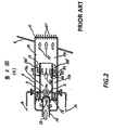
- Patent publication JP61285386 with reference to figure 2 , teaches a partially external installation steam dump device constituted in a double structure form including spray nozzles provided on the wall surface of the device.
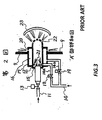
- patent publication JP57049004 discloses a steam dump device, depicted in figure 3 , having a configuration aiming to prevent a internal protection of a barrel body of a condenser caused by in-flow of bypassing steam, wherein a cooling means is arranged in a turbine bypass inlet pipe as a double pipe structure near an open end of the condenser of a turbine bypass pipe.
- a further object of the present invention is to provide a condenser as defined in dependent claim 9.
- a steam dump device for a nuclear power plant configured to be installed within a bypass line leading from a boiler to a condenser and comprising an elongated header vessel comprising a means for receiving steam, wherein the elongated vessel extends horizontally and comprises a top perforated diaphragm and a bottom perforated diaphragm opposed thereto, the top and bottom perforated diaphragms being arranged on respective portions on a wall of the vessel; an external baffle plates assembly partially enclosing the header vessel and comprising a top plate and a bottom plate, the baffle plates assembly defining lateral steam openings.
- the top perforated diaphragm has a greater area than the bottom perforated diaphragm.
- the ratio between the areas of the top diaphragm versus the bottom one is comprised within a range from 1 (areas equal to each other) to 1,4 (top area being 40% greater than the bottom area).
- the ratio is substantially equal to 1,2.
- the header vessel comprises a couple of consecutive and separated top perforated diaphragms arranged along the top portion of the lateral wall of the vessel, and a couple of consecutive and separated bottom perforated diaphragms arranged along the bottom portion of the wall.
- the header vessel comprises elliptical terminal heads at both ends.
- the means for receiving steam comprises one or more steam inlets arranged at one upwards elliptical head and is configured to be connected to a steam pipe, the steam inlet comprising a multi holed hemispherical head.
- the steam dump device further comprises spray nozzles arranged along the baffle plates assembly.
- the steam dump device comprises sliding support feet configured to allow a longitudinal movement of the vessel on a supporting structure.
- a condenser for a nuclear power plant which comprises one or more steam dump devices according to the present invention, each steam dump device being located inside the condenser.
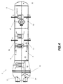
- FIG 4 it is shown a lateral view of a header vessel 3, which forms part of a steam dump device according to the present invention (not shown in the figure).
- the header vessel 3 is configured to be installed along a bypass line (not shown) leading from a boiler to a condenser and is particularly designed to cool off a steam being diverted from the boiler to the condenser without evolving in a turbine to produce useful work.
- Such bypass line may be used, as mentioned above, during start-up or run-down of the plant or in case, during normal operation, a problem with the turbine might occur which would require the steam to bypass the turbine stage.
- header vessel 3 presents an elongated shape extending horizontally within a supporting structure (not shown).
- header vessel 3 has a substantially cylindrical shape having elliptical terminal heads 31, 32 at both of its end.
- Means 14 for receiving steam preferably in the form of a steam inlet 14, is located at an upwards terminal elliptical head 31.
- header vessel comprises four steam inlets 14 (only two visible in the view of figure 4 ), but it may be appreciated that number of inlets 14 may be only one or more.
- Each steam inlet 14 is adapted to be connected to a steam pipe (not shown) of the bypass line.
- header vessel 3 The hot steam reaching the header vessel 3 goes through a first chamber 60, having convergent external walls, and then arrives in a second chamber 70, having a wall 8.
- Cooling chamber 70 comprises a top perforated diaphragm 41 and a bottom perforated diaphragm 51 opposed thereto, arranged on respective top and bottom portions 6, 7 of the wall 8.
- header vessel 3 comprises a further top perforated diaphragm 42, arranged on the top portion 6 of the wall 8, the top perforated diaphragm 42 being subsequent to and separated from the perforated diaphragm 41.
- header vessel 3 comprises a further bottom perforated diaphragm 52, arranged on the bottom portion 7 of the wall 8, the bottom perforated diaphragm 52 being subsequent to and separated from the perforated diaphragm 51.
- Top and bottom perforated diaphragms 42 and 52 are located opposed to each other in a similar way as for perforated diaphragms 41 and 51.
- the steam reaching second chamber 70 is expelled from the vessel 3 through perforated diaphragms, hence along a vertical direction indicated by arrows F.
- top perforated diaphragms 41 and 42 are visible, which are located on the top portion 6 of the wall 8 of the header vessel 3.
- bottom perforated diaphragms 51 and 52 are visible, which are located on the bottom portion 7 of the wall 8 of the header vessel 3.
- top diaphragms 41 and 42 have a greater area than correspondent bottom perforated diaphragms 51 and 52.
- maximum efficiency is reached with a ratio of 1,2 between areas of opposed top and bottom perforated diaphragms 41, 51 and 42, 52, meaning that the top diaphragm has an area which is substantially 20% greater than the bottom one.
- Perforated diaphragms may be constituted by a plate having drilled orifices, from which steam pressure can fall down while exiting the vessel 3.
- each steam inlet 14 comprises a multi holed hemispherical head 16, through which the steam is directed when entering in the first cooling chamber 60.
- Multi holed hemispherical heads 16 in the first chamber 60 may be considered as a primary orifice stage of the vessel, while the perforated diaphragms 41, 42, 51, 52 arranged on the wall 8 in the second chamber 70 may be considered as a secondary orifice stage of the vessel.
- FIG. 6 it is depicted an external baffle plates assembly 9, forming part of the steam dump device according to the invention (not shown in its entirety), which partially encloses the header vessel illustrated in preceding figures 4-5 .
- Baffle plates assembly 9 includes a top plate 10,a bottom plate 11 and opposed closing plates 80 and defines lateral steam openings 12.
- the vessel is located within the baffle plates assembly and the steam, after having passed through top and bottom perforated diaphragms, reaches top and bottom plates 10, 11 of the baffle plates assembly 9. Then, it is diverted by the baffle plates assembly towards the sides, and reaches the condenser through the lateral steam openings 12.
- spray nozzles may be arranged along top and bottom baffle plates 10 and 11. More in particular, according to a preferred and non-limiting embodiment, four pipes (not shown) are arranged within the top and bottom plates 10, 11, two within the top baffle plate 10 and two within the bottom baffle plate 11. A bolted blind flange shut their extremity. Spray nozzles are positioned along each pipe at regular intervals to inject condensate into the main steam coming from the secondary orifice stage of the header vessel.
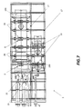
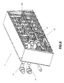
- a condenser 2 more particularly an inside structure thereof, respectively in a lateral and perspective view, which comprises a primary steam dump device 100 and a secondary steam dump device 200.
- the primary steam dump device 100 may be used during normal operation of the power plant, in case of any need of bypassing the turbine stage, while the secondary steam dump device 200 may be used during start-up or and/or run down of the machinery.
- primary and secondary steam dump devices are equal to each other expect for the fact that the first one may accept and elaborate a greater flow of steam with respect to the second one.
- condenser 2 may also be provided with only one steam dump device according to the invention.
- Primary and secondary steam dump devices 100 and 200 are located inside the condenser 2.
- steam dump device 100 By means of inlet pipes 15 which pass through a condenser wall, and enters the header vessel 3 and subsequently is expelled within the condenser through lateral openings defined by the baffle plates assembly 9, enclosing the header vessel 3.
- steam dump device advantageously comprises sliding support feet 20 which are configured to allow a longitudinal movement (due to thermal expansion and contraction) of the header vessel 3 on a supporting structure 17, while blocking the vertical one.
- an inspection cover is bolted to a manhole on the side of the header vessel.
Landscapes
- Engineering & Computer Science (AREA)
- General Engineering & Computer Science (AREA)
- Mechanical Engineering (AREA)
- Combustion & Propulsion (AREA)
- Chemical & Material Sciences (AREA)
- Physics & Mathematics (AREA)
- High Energy & Nuclear Physics (AREA)
- Plasma & Fusion (AREA)
- Thermal Sciences (AREA)
- Business, Economics & Management (AREA)
- Emergency Management (AREA)
- Structure Of Emergency Protection For Nuclear Reactors (AREA)
- Control Of Turbines (AREA)
- Jet Pumps And Other Pumps (AREA)
Abstract
Description
- The present invention generally relates to a nuclear power plant, and more particular to a steam dump device and a condenser for a nuclear power plant.
- As well known, in a power plant a steam dump device is typically located downstream a bypass line arranged between the boiler and the condenser. Such bypass line is required, for example, during start-up or run-down operations of the plant where the steam has a high- content of water which could damage the turbine blading.
- The turbine bypass system hence permits start-up and rapid turbine load reductions, which includes turbine tripping, without causing a reactor trip or relief valve operation. The function of the dump steam diffusers is to breakdown the pressure of the dump steam in stages and to desuperheat it before it enters in the condenser.
- To this purpose, the steam dump device permits the introduction of the steam into the condenser by operating a reduction of its temperature and the pressure values. Generally, the steam dump device includes a vessel comprising means to reduce pressure and temperature of the steam and to efficiently guide the steam into the condenser.
- Patent publication
US6189871 , with reference tofigure 1 , discloses a partial external installation of asteam dump device 1 arranged on a bypass line connecting the boiler to thecondenser 9. In particular, thesteam dump device 1 includes a firstperforated diaphragm 3, acooling chamber 4 and a secondperforated diaphragm 8. - The second
perforated diaphragm 8 of thecooling chamber 4 projects into thecondenser neck 7 of thecondenser 9. - Patent publication
JP61285386 figure 2 , teaches a partially external installation steam dump device constituted in a double structure form including spray nozzles provided on the wall surface of the device. Lastly, patent publicationJP57049004 figure 3 , having a configuration aiming to prevent a internal protection of a barrel body of a condenser caused by in-flow of bypassing steam, wherein a cooling means is arranged in a turbine bypass inlet pipe as a double pipe structure near an open end of the condenser of a turbine bypass pipe. - However, solutions above illustrated still don't provide an optimum efficiency in terms of properly guiding the steam into the condenser avoiding damages of the condenser neck due to vibration and/or thermal expansion and large flow of nuclear power plants.
- It is an object of the present invention to solve the aforementioned technical problems by providing a steam dump device as substantially defined according to
independent claim 1. - Moreover, a further object of the present invention is to provide a condenser as defined in
dependent claim 9. - According to an aspect of the invention, this object is obtained by a steam dump device for a nuclear power plant, configured to be installed within a bypass line leading from a boiler to a condenser and comprising an elongated header vessel comprising a means for receiving steam, wherein the elongated vessel extends horizontally and comprises a top perforated diaphragm and a bottom perforated diaphragm opposed thereto, the top and bottom perforated diaphragms being arranged on respective portions on a wall of the vessel; an external baffle plates assembly partially enclosing the header vessel and comprising a top plate and a bottom plate, the baffle plates assembly defining lateral steam openings.
- According to a preferred aspect of the invention, the top perforated diaphragm has a greater area than the bottom perforated diaphragm.
- According to a preferred aspect of the invention, the ratio between the areas of the top diaphragm versus the bottom one is comprised within a range from 1 (areas equal to each other) to 1,4 (top area being 40% greater than the bottom area).
- More preferably, the ratio is substantially equal to 1,2. According to a preferred aspect of the invention, wherein the header vessel comprises a couple of consecutive and separated top perforated diaphragms arranged along the top portion of the lateral wall of the vessel, and a couple of consecutive and separated bottom perforated diaphragms arranged along the bottom portion of the wall.
- According to a preferred aspect of the invention, the header vessel comprises elliptical terminal heads at both ends.
- According to a preferred aspect of the invention, the means for receiving steam comprises one or more steam inlets arranged at one upwards elliptical head and is configured to be connected to a steam pipe, the steam inlet comprising a multi holed hemispherical head.
- According to a preferred aspect of the invention, the steam dump device further comprises spray nozzles arranged along the baffle plates assembly.
- According to a preferred aspect of the invention, the steam dump device comprises sliding support feet configured to allow a longitudinal movement of the vessel on a supporting structure.
- According to a further aspect of the invention, it is provided a condenser for a nuclear power plant, which comprises one or more steam dump devices according to the present invention, each steam dump device being located inside the condenser.
- The objects, advantages and other features of the present invention will become more apparent upon reading of the following non-restrictive description of preferred embodiments thereof, given for the purpose of exemplification only, with reference to the accompany drawing, through which similar reference numerals may be used to refer to similar elements, and in which:
-
Figures 1-3 show different steam dump device arrangements according to prior art; -
Figure 4 shows a lateral view of a header vessel forming part of a steam dump device according to the present invention; -
Figure 5 shows a top and bottom views of the header vessel offigure 4 ; -
Figure 6 shows a perspective view of a baffle plate assembly enclosing the header vessel offigures 4 and5 ; -
Figure 7 and8 depict respectively a lateral and a perspective view of a condenser according to the present invention. - A preferred and non-limiting embodiment will be now described in detail with reference to the above referenced drawings.
- With reference to
figure 4 , it is shown a lateral view of aheader vessel 3, which forms part of a steam dump device according to the present invention (not shown in the figure). Theheader vessel 3 is configured to be installed along a bypass line (not shown) leading from a boiler to a condenser and is particularly designed to cool off a steam being diverted from the boiler to the condenser without evolving in a turbine to produce useful work. Such bypass line may be used, as mentioned above, during start-up or run-down of the plant or in case, during normal operation, a problem with the turbine might occur which would require the steam to bypass the turbine stage. - More in particular,
header vessel 3 presents an elongated shape extending horizontally within a supporting structure (not shown). Preferably,header vessel 3 has a substantially cylindrical shape havingelliptical terminal heads steam inlet 14, is located at an upwards terminalelliptical head 31. In the preferred and non-limiting embodiment herein disclosed, header vessel comprises four steam inlets 14 (only two visible in the view offigure 4 ), but it may be appreciated that number ofinlets 14 may be only one or more. Eachsteam inlet 14 is adapted to be connected to a steam pipe (not shown) of the bypass line. The hot steam reaching theheader vessel 3 goes through afirst chamber 60, having convergent external walls, and then arrives in asecond chamber 70, having awall 8.Cooling chamber 70 comprises a topperforated diaphragm 41 and a bottom perforateddiaphragm 51 opposed thereto, arranged on respective top andbottom portions wall 8. Preferably,header vessel 3 comprises a further top perforateddiaphragm 42, arranged on thetop portion 6 of thewall 8, the top perforateddiaphragm 42 being subsequent to and separated from theperforated diaphragm 41. Similarly,header vessel 3 comprises a further bottom perforateddiaphragm 52, arranged on thebottom portion 7 of thewall 8, the bottom perforateddiaphragm 52 being subsequent to and separated from theperforated diaphragm 51. Top and bottom perforateddiaphragms perforated diaphragms second chamber 70 is expelled from thevessel 3 through perforated diaphragms, hence along a vertical direction indicated by arrows F. - Making now reference to next
figure 5 , it is shown (above) a top view of theheader vessel 3 and (below) a bottom view of the same. - In the top view, top
perforated diaphragms top portion 6 of thewall 8 of theheader vessel 3. - In the bottom view, bottom perforated
diaphragms bottom portion 7 of thewall 8 of theheader vessel 3. - In particular, it has been found that a remarkable efficiency in the cooling process of the steam is achievable when
top diaphragms diaphragms diaphragms vessel 3. - Still with reference to
figure 5 bottom view, eachsteam inlet 14 comprises a multi holedhemispherical head 16, through which the steam is directed when entering in thefirst cooling chamber 60. - Multi holed
hemispherical heads 16 in thefirst chamber 60 may be considered as a primary orifice stage of the vessel, while theperforated diaphragms wall 8 in thesecond chamber 70 may be considered as a secondary orifice stage of the vessel. - With reference to next
figure 6 , it is depicted an externalbaffle plates assembly 9, forming part of the steam dump device according to the invention (not shown in its entirety), which partially encloses the header vessel illustrated in precedingfigures 4-5 . -
Baffle plates assembly 9 includes atop plate 10,abottom plate 11 and opposedclosing plates 80 and defineslateral steam openings 12. The vessel is located within the baffle plates assembly and the steam, after having passed through top and bottom perforated diaphragms, reaches top andbottom plates baffle plates assembly 9. Then, it is diverted by the baffle plates assembly towards the sides, and reaches the condenser through thelateral steam openings 12. Additionally, to further improve the cooling process, spray nozzles may be arranged along top andbottom baffle plates bottom plates top baffle plate 10 and two within thebottom baffle plate 11. A bolted blind flange shut their extremity. Spray nozzles are positioned along each pipe at regular intervals to inject condensate into the main steam coming from the secondary orifice stage of the header vessel. - With reference to
figures 7 and8 , it is shown acondenser 2, more particularly an inside structure thereof, respectively in a lateral and perspective view, which comprises a primarysteam dump device 100 and a secondarysteam dump device 200. In particular, the primarysteam dump device 100 may be used during normal operation of the power plant, in case of any need of bypassing the turbine stage, while the secondarysteam dump device 200 may be used during start-up or and/or run down of the machinery. However, it will be appreciated that primary and secondary steam dump devices are equal to each other expect for the fact that the first one may accept and elaborate a greater flow of steam with respect to the second one. It may as well be appreciated thatcondenser 2 may also be provided with only one steam dump device according to the invention. Primary and secondarysteam dump devices condenser 2. - Reference will be made to primary
steam dump device 100, but it will be appreciated that same disclosure is applicable, mutatis mutandis, to the secondarysteam dump device 200. - Steam reaches
steam dump device 100 by means ofinlet pipes 15 which pass through a condenser wall, and enters theheader vessel 3 and subsequently is expelled within the condenser through lateral openings defined by thebaffle plates assembly 9, enclosing theheader vessel 3. Furthermore, steam dump device advantageously comprises slidingsupport feet 20 which are configured to allow a longitudinal movement (due to thermal expansion and contraction) of theheader vessel 3 on a supportingstructure 17, while blocking the vertical one. Preferably, an inspection cover is bolted to a manhole on the side of the header vessel. - While the invention has been described in detail in connection with only a limited number of embodiments, it should be readily understood that the invention is not limited to such disclosed embodiments. Rather, the invention can be modified to incorporate any number of variations, alterations, substitutions or equivalent arrangements not heretofore described, but which are commensurate with the spirit and scope of the invention. Additionally, while various embodiments of the invention have been described, it is to be understood that aspects of the invention may include only some of the described embodiments. Accordingly, the invention is not to be seen as limited by the foregoing description, but is only limited by the scope of the appended claims.
Claims (10)
- A steam dump device (100, 200) for a nuclear power plant, configured to be installed within a bypass line leading from a boiler to a condenser (2) comprising:- an elongated header vessel (3) comprising a means (14) for receiving steam, said elongated vessel (3) extending horizontally and comprising a top perforated diaphragm (41) and a bottom perforated diaphragm (51) opposed thereto, said top and bottom perforated diaphragms (41, 51) arranged on respective top and bottom portions (6, 7) on a wall (8) of the header vessel (3);- external baffle plates assembly (9) partially enclosing said header vessel (3) and comprising a top plate (10) and a bottom plate (11), said baffle plates assembly (9) defining lateral steam openings (12).
- The steam dump device (100, 200) according to the preceding claim, wherein said top perforated diaphragm (41) has a greater area than said bottom perforated diaphragm (51).
- The steam dump device (100, 200) according to the preceding claim, wherein a ratio between the areas of said top perforated diaphragm (41) and said bottom perforated diaphragm (51) is comprised within a range 1 - 1,4.
- The steam dump device (100, 200) according to the preceding claim, wherein said ratio is substantially equal to 1,2.
- The steam dump device (100, 200) according to any of the preceding claims, comprising a couple of consecutive and separated top perforated diaphragms (41, 42) arranged along the top portion (6) of the wall (8), and a couple of consecutive and separated bottom perforated diaphragms (51, 52) arranged along the bottom portion (7) of the wall (8).
- The steam dump device (100, 200) according to any of the preceding claims, wherein said header vessel (3) comprises elliptical terminal heads (31, 32) at both ends.
- The steam dump device (100, 200) according to the preceding claim, wherein said means (14) for receiving steam comprises a steam inlet (14) arranged at one upwards elliptical head (31) and configured to be connected to a steam pipe (15), said inlet (14) comprising a multi holed hemispherical diaphragm (16).
- The steam dump device (100, 200) according to any of the preceding claims, further comprising spray nozzles arranged along said baffle plates (9).
- The steam dump device (100, 200) according to any of the preceding claims, further comprising sliding support feet (20) configured to allow a longitudinal movement of the header vessel (3) on a supporting structure (17).
- Condenser (2) of a nuclear power plant, characterised in that it comprises one or more steam dump devices (100, 200) according to any of the preceding claims, each steam dump device (100, 200) being located inside the condenser (2).
Priority Applications (4)
| Application Number | Priority Date | Filing Date | Title |
|---|---|---|---|
| EP15290158.3A EP3104107B1 (en) | 2015-06-12 | 2015-06-12 | Steam dump device for a nuclear power plant |
| RU2016121774A RU2702346C2 (en) | 2015-06-12 | 2016-06-02 | Steam discharge device for nuclear power plant |
| CN201610400575.1A CN106246250B (en) | 2015-06-12 | 2016-06-08 | Steam dumpers for nuclear power plants |
| US15/177,403 US10480779B2 (en) | 2015-06-12 | 2016-06-09 | Steam dump device for a nuclear power plant |
Applications Claiming Priority (1)
| Application Number | Priority Date | Filing Date | Title |
|---|---|---|---|
| EP15290158.3A EP3104107B1 (en) | 2015-06-12 | 2015-06-12 | Steam dump device for a nuclear power plant |
Publications (2)
| Publication Number | Publication Date |
|---|---|
| EP3104107A1 true EP3104107A1 (en) | 2016-12-14 |
| EP3104107B1 EP3104107B1 (en) | 2018-08-08 |
Family
ID=53539618
Family Applications (1)
| Application Number | Title | Priority Date | Filing Date |
|---|---|---|---|
| EP15290158.3A Active EP3104107B1 (en) | 2015-06-12 | 2015-06-12 | Steam dump device for a nuclear power plant |
Country Status (4)
| Country | Link |
|---|---|
| US (1) | US10480779B2 (en) |
| EP (1) | EP3104107B1 (en) |
| CN (1) | CN106246250B (en) |
| RU (1) | RU2702346C2 (en) |
Cited By (1)
| Publication number | Priority date | Publication date | Assignee | Title |
|---|---|---|---|---|
| EP3591179A1 (en) * | 2018-07-03 | 2020-01-08 | Siemens Aktiengesellschaft | Deflection steam feed |
Families Citing this family (1)
| Publication number | Priority date | Publication date | Assignee | Title |
|---|---|---|---|---|
| US10731513B2 (en) * | 2017-01-31 | 2020-08-04 | Control Components, Inc. | Compact multi-stage condenser dump device |
Citations (5)
| Publication number | Priority date | Publication date | Assignee | Title |
|---|---|---|---|---|
| JPS5749004A (en) | 1980-09-10 | 1982-03-20 | Hitachi Ltd | In-flowing device for bypassing steam to condenser of turbine |
| JPS61285386A (en) | 1985-06-12 | 1986-12-16 | Hitachi Ltd | Pressure and temperature reducing device |
| US5268939A (en) * | 1992-10-19 | 1993-12-07 | General Electric Company | Control system and method for a nuclear reactor |
| US6189871B1 (en) | 1998-04-30 | 2001-02-20 | Asea Brown Boveri Ag | Steam introduction device in a power plant |
| US20150020499A1 (en) * | 2013-07-17 | 2015-01-22 | Kabushiki Kaisha Toshiba | Control valve control method and control device, and power generating plant utilizing same |
Family Cites Families (10)
| Publication number | Priority date | Publication date | Assignee | Title |
|---|---|---|---|---|
| US3195871A (en) * | 1961-08-16 | 1965-07-20 | Gibbs & Hill Inc | Steam expansion chamber |
| FR1446215A (en) * | 1965-09-04 | 1966-07-15 | Escher Wyss Sa Soc | Steam regulator for low pressure bypass devices of steam power plants |
| JPS599492A (en) * | 1982-07-09 | 1984-01-18 | Hitachi Ltd | condenser |
| RU94041492A (en) * | 1994-11-16 | 1996-09-20 | Опытно-конструкторское бюро машиностроения | Nuclear power plant |
| US7055324B2 (en) * | 2003-03-12 | 2006-06-06 | Fisher Controls International Llc | Noise abatement device and method for air-cooled condensing systems |
| DE102006017004B3 (en) * | 2006-04-11 | 2007-10-25 | Airbus Deutschland Gmbh | Device for mixing fresh air and heating air and use thereof in a ventilation system of an aircraft |
| WO2010091342A2 (en) * | 2009-02-06 | 2010-08-12 | Clyde Gergemann, Inc. | Sootblower having a nozzle with deep reaching jets and edge cleaning jets |
| RU84616U1 (en) * | 2009-02-24 | 2009-07-10 | Ооо "Нева-Металл" | VEHICLE NUCLEAR POWER PLANT |
| RU120144U1 (en) * | 2012-06-07 | 2012-09-10 | Открытое акционерное общество "Всероссийский дважды ордена Трудового Красного Знамени теплотехнический научно-исследовательский институт" | POWER UNIT WITH THE UNITED STOP-CONTROL VALVE ON THE LINES OF STEAM CONDITION TO THE STEAM TURBINE AND WITH THE STOP VALVES ON THE LINES OF STEAM DISCHARGE TO THE CONDENSER |
| US9593598B2 (en) * | 2014-05-13 | 2017-03-14 | Holtec International | Steam conditioning system |
-
2015
- 2015-06-12 EP EP15290158.3A patent/EP3104107B1/en active Active
-
2016
- 2016-06-02 RU RU2016121774A patent/RU2702346C2/en active
- 2016-06-08 CN CN201610400575.1A patent/CN106246250B/en active Active
- 2016-06-09 US US15/177,403 patent/US10480779B2/en active Active
Patent Citations (5)
| Publication number | Priority date | Publication date | Assignee | Title |
|---|---|---|---|---|
| JPS5749004A (en) | 1980-09-10 | 1982-03-20 | Hitachi Ltd | In-flowing device for bypassing steam to condenser of turbine |
| JPS61285386A (en) | 1985-06-12 | 1986-12-16 | Hitachi Ltd | Pressure and temperature reducing device |
| US5268939A (en) * | 1992-10-19 | 1993-12-07 | General Electric Company | Control system and method for a nuclear reactor |
| US6189871B1 (en) | 1998-04-30 | 2001-02-20 | Asea Brown Boveri Ag | Steam introduction device in a power plant |
| US20150020499A1 (en) * | 2013-07-17 | 2015-01-22 | Kabushiki Kaisha Toshiba | Control valve control method and control device, and power generating plant utilizing same |
Non-Patent Citations (1)
| Title |
|---|
| HWA WOON BYEON ET AL: "DESIGNING A STANDARD THERMAL POWER PLANT FOR DAILY STARTUP/SHUTDOWNTHE HP BYPASS CONTROL AND SAFETY FUNCTION", TECHNICAL PAPER OF ISA, INSTRUMENT SOCIETY OF AMERICA, vol. 51, no. PART 02, 1 January 1996 (1996-01-01), pages 1295 - 1305, XP000639432, ISSN: 1054-0032 * |
Cited By (3)
| Publication number | Priority date | Publication date | Assignee | Title |
|---|---|---|---|---|
| EP3591179A1 (en) * | 2018-07-03 | 2020-01-08 | Siemens Aktiengesellschaft | Deflection steam feed |
| WO2020007609A1 (en) * | 2018-07-03 | 2020-01-09 | Siemens Aktiengesellschaft | Steam bypass conduit |
| RU2756941C1 (en) * | 2018-07-03 | 2021-10-07 | Сименс Энерджи Глоубл Гмбх Унд Ко. Кг | Steam input in the bypass |
Also Published As
| Publication number | Publication date |
|---|---|
| RU2016121774A (en) | 2017-12-07 |
| RU2702346C2 (en) | 2019-10-08 |
| RU2016121774A3 (en) | 2019-08-28 |
| CN106246250A (en) | 2016-12-21 |
| US20160363314A1 (en) | 2016-12-15 |
| US10480779B2 (en) | 2019-11-19 |
| EP3104107B1 (en) | 2018-08-08 |
| CN106246250B (en) | 2020-02-28 |
Similar Documents
| Publication | Publication Date | Title |
|---|---|---|
| US7946383B2 (en) | Acoustic load mitigator | |
| US7784279B2 (en) | Steam valve and steam turbine plant | |
| US6237542B1 (en) | Heat recovery boiler and hot banking releasing method thereof | |
| EP2503105B1 (en) | Steam valve device and steam turbine plant | |
| EP2634378B1 (en) | Low pressure steam turbine | |
| EP3104107B1 (en) | Steam dump device for a nuclear power plant | |
| EP3006683B1 (en) | Diverting system | |
| JP2001193417A (en) | Directly contacting type condenser for axial-flow exhaust turbine | |
| US3379616A (en) | Heat extraction device for nuclear reactor | |
| US6602046B2 (en) | Diffusor without any pulsation of the shock boundary layer, and a method for suppressing the shock boundary layer pulsation in diffusors | |
| KR101398101B1 (en) | Multiple stage steam dump decompression | |
| US20120023944A1 (en) | Device for phase separation of a multiphase fluid flow, steam turbine plant having such a device, and associated operating method | |
| CN100368658C (en) | steam turbine | |
| EP3610137A1 (en) | Steam turbine and method for operating same | |
| CN105408590A (en) | Turbine condenser for a steam turbine | |
| JP7102359B2 (en) | Condenser | |
| EP3040525B1 (en) | Multi stage steam turbine for power generation | |
| CN205279049U (en) | Hydrophobic flash vessel of steam of anti soda erosion | |
| Nadig | Considerations in Converting a Dual Shell or a Dual Pressure Coal Fired Plant Condenser Into a Combined Cycle Plant Condenser | |
| JP6294844B2 (en) | Moisture separator | |
| JP4945511B2 (en) | Plant with piping having a branching section and boiling water nuclear power plant | |
| EP3299720A1 (en) | Combustor front assembly for a gas turbine | |
| Avrutsky et al. | An analysis of problems arising during operation of the perm district power plant 800-MW power unit at sliding pressure | |
| JP2007170700A (en) | Moisture separation equipment | |
| JPH0282003A (en) | Vent system of supply water heater of power plant by steam turbine |
Legal Events
| Date | Code | Title | Description |
|---|---|---|---|
| PUAI | Public reference made under article 153(3) epc to a published international application that has entered the european phase |
Free format text: ORIGINAL CODE: 0009012 |
|
| STAA | Information on the status of an ep patent application or granted ep patent |
Free format text: STATUS: THE APPLICATION HAS BEEN PUBLISHED |
|
| AK | Designated contracting states |
Kind code of ref document: A1 Designated state(s): AL AT BE BG CH CY CZ DE DK EE ES FI FR GB GR HR HU IE IS IT LI LT LU LV MC MK MT NL NO PL PT RO RS SE SI SK SM TR |
|
| AX | Request for extension of the european patent |
Extension state: BA ME |
|
| STAA | Information on the status of an ep patent application or granted ep patent |
Free format text: STATUS: REQUEST FOR EXAMINATION WAS MADE |
|
| 17P | Request for examination filed |
Effective date: 20170614 |
|
| RBV | Designated contracting states (corrected) |
Designated state(s): AL AT BE BG CH CY CZ DE DK EE ES FI FR GB GR HR HU IE IS IT LI LT LU LV MC MK MT NL NO PL PT RO RS SE SI SK SM TR |
|
| RIC1 | Information provided on ipc code assigned before grant |
Ipc: F22B 37/00 20060101ALI20171130BHEP Ipc: F01K 9/00 20060101ALI20171130BHEP Ipc: G21D 3/04 20060101ALI20171130BHEP Ipc: F22B 35/04 20060101ALI20171130BHEP Ipc: F22G 5/12 20060101ALI20171130BHEP Ipc: F01K 9/04 20060101ALI20171130BHEP Ipc: F28B 9/02 20060101AFI20171130BHEP |
|
| GRAP | Despatch of communication of intention to grant a patent |
Free format text: ORIGINAL CODE: EPIDOSNIGR1 |
|
| STAA | Information on the status of an ep patent application or granted ep patent |
Free format text: STATUS: GRANT OF PATENT IS INTENDED |
|
| INTG | Intention to grant announced |
Effective date: 20180108 |
|
| GRAS | Grant fee paid |
Free format text: ORIGINAL CODE: EPIDOSNIGR3 |
|
| GRAA | (expected) grant |
Free format text: ORIGINAL CODE: 0009210 |
|
| STAA | Information on the status of an ep patent application or granted ep patent |
Free format text: STATUS: THE PATENT HAS BEEN GRANTED |
|
| AK | Designated contracting states |
Kind code of ref document: B1 Designated state(s): AL AT BE BG CH CY CZ DE DK EE ES FI FR GB GR HR HU IE IS IT LI LT LU LV MC MK MT NL NO PL PT RO RS SE SI SK SM TR |
|
| REG | Reference to a national code |
Ref country code: GB Ref legal event code: FG4D |
|
| REG | Reference to a national code |
Ref country code: CH Ref legal event code: EP Ref country code: AT Ref legal event code: REF Ref document number: 1027487 Country of ref document: AT Kind code of ref document: T Effective date: 20180815 |
|
| REG | Reference to a national code |
Ref country code: IE Ref legal event code: FG4D |
|
| REG | Reference to a national code |
Ref country code: DE Ref legal event code: R096 Ref document number: 602015014594 Country of ref document: DE |
|
| REG | Reference to a national code |
Ref country code: NL Ref legal event code: MP Effective date: 20180808 |
|
| REG | Reference to a national code |
Ref country code: LT Ref legal event code: MG4D |
|
| REG | Reference to a national code |
Ref country code: AT Ref legal event code: MK05 Ref document number: 1027487 Country of ref document: AT Kind code of ref document: T Effective date: 20180808 |
|
| PG25 | Lapsed in a contracting state [announced via postgrant information from national office to epo] |
Ref country code: LT Free format text: LAPSE BECAUSE OF FAILURE TO SUBMIT A TRANSLATION OF THE DESCRIPTION OR TO PAY THE FEE WITHIN THE PRESCRIBED TIME-LIMIT Effective date: 20180808 Ref country code: PL Free format text: LAPSE BECAUSE OF FAILURE TO SUBMIT A TRANSLATION OF THE DESCRIPTION OR TO PAY THE FEE WITHIN THE PRESCRIBED TIME-LIMIT Effective date: 20180808 Ref country code: RS Free format text: LAPSE BECAUSE OF FAILURE TO SUBMIT A TRANSLATION OF THE DESCRIPTION OR TO PAY THE FEE WITHIN THE PRESCRIBED TIME-LIMIT Effective date: 20180808 Ref country code: AT Free format text: LAPSE BECAUSE OF FAILURE TO SUBMIT A TRANSLATION OF THE DESCRIPTION OR TO PAY THE FEE WITHIN THE PRESCRIBED TIME-LIMIT Effective date: 20180808 Ref country code: IS Free format text: LAPSE BECAUSE OF FAILURE TO SUBMIT A TRANSLATION OF THE DESCRIPTION OR TO PAY THE FEE WITHIN THE PRESCRIBED TIME-LIMIT Effective date: 20181208 Ref country code: GR Free format text: LAPSE BECAUSE OF FAILURE TO SUBMIT A TRANSLATION OF THE DESCRIPTION OR TO PAY THE FEE WITHIN THE PRESCRIBED TIME-LIMIT Effective date: 20181109 Ref country code: NO Free format text: LAPSE BECAUSE OF FAILURE TO SUBMIT A TRANSLATION OF THE DESCRIPTION OR TO PAY THE FEE WITHIN THE PRESCRIBED TIME-LIMIT Effective date: 20181108 Ref country code: FI Free format text: LAPSE BECAUSE OF FAILURE TO SUBMIT A TRANSLATION OF THE DESCRIPTION OR TO PAY THE FEE WITHIN THE PRESCRIBED TIME-LIMIT Effective date: 20180808 Ref country code: SE Free format text: LAPSE BECAUSE OF FAILURE TO SUBMIT A TRANSLATION OF THE DESCRIPTION OR TO PAY THE FEE WITHIN THE PRESCRIBED TIME-LIMIT Effective date: 20180808 Ref country code: BG Free format text: LAPSE BECAUSE OF FAILURE TO SUBMIT A TRANSLATION OF THE DESCRIPTION OR TO PAY THE FEE WITHIN THE PRESCRIBED TIME-LIMIT Effective date: 20181108 Ref country code: NL Free format text: LAPSE BECAUSE OF FAILURE TO SUBMIT A TRANSLATION OF THE DESCRIPTION OR TO PAY THE FEE WITHIN THE PRESCRIBED TIME-LIMIT Effective date: 20180808 |
|
| PG25 | Lapsed in a contracting state [announced via postgrant information from national office to epo] |
Ref country code: HR Free format text: LAPSE BECAUSE OF FAILURE TO SUBMIT A TRANSLATION OF THE DESCRIPTION OR TO PAY THE FEE WITHIN THE PRESCRIBED TIME-LIMIT Effective date: 20180808 Ref country code: AL Free format text: LAPSE BECAUSE OF FAILURE TO SUBMIT A TRANSLATION OF THE DESCRIPTION OR TO PAY THE FEE WITHIN THE PRESCRIBED TIME-LIMIT Effective date: 20180808 Ref country code: LV Free format text: LAPSE BECAUSE OF FAILURE TO SUBMIT A TRANSLATION OF THE DESCRIPTION OR TO PAY THE FEE WITHIN THE PRESCRIBED TIME-LIMIT Effective date: 20180808 |
|
| PG25 | Lapsed in a contracting state [announced via postgrant information from national office to epo] |
Ref country code: CZ Free format text: LAPSE BECAUSE OF FAILURE TO SUBMIT A TRANSLATION OF THE DESCRIPTION OR TO PAY THE FEE WITHIN THE PRESCRIBED TIME-LIMIT Effective date: 20180808 Ref country code: RO Free format text: LAPSE BECAUSE OF FAILURE TO SUBMIT A TRANSLATION OF THE DESCRIPTION OR TO PAY THE FEE WITHIN THE PRESCRIBED TIME-LIMIT Effective date: 20180808 Ref country code: ES Free format text: LAPSE BECAUSE OF FAILURE TO SUBMIT A TRANSLATION OF THE DESCRIPTION OR TO PAY THE FEE WITHIN THE PRESCRIBED TIME-LIMIT Effective date: 20180808 Ref country code: EE Free format text: LAPSE BECAUSE OF FAILURE TO SUBMIT A TRANSLATION OF THE DESCRIPTION OR TO PAY THE FEE WITHIN THE PRESCRIBED TIME-LIMIT Effective date: 20180808 |
|
| REG | Reference to a national code |
Ref country code: DE Ref legal event code: R097 Ref document number: 602015014594 Country of ref document: DE |
|
| PG25 | Lapsed in a contracting state [announced via postgrant information from national office to epo] |
Ref country code: SK Free format text: LAPSE BECAUSE OF FAILURE TO SUBMIT A TRANSLATION OF THE DESCRIPTION OR TO PAY THE FEE WITHIN THE PRESCRIBED TIME-LIMIT Effective date: 20180808 Ref country code: DK Free format text: LAPSE BECAUSE OF FAILURE TO SUBMIT A TRANSLATION OF THE DESCRIPTION OR TO PAY THE FEE WITHIN THE PRESCRIBED TIME-LIMIT Effective date: 20180808 Ref country code: SM Free format text: LAPSE BECAUSE OF FAILURE TO SUBMIT A TRANSLATION OF THE DESCRIPTION OR TO PAY THE FEE WITHIN THE PRESCRIBED TIME-LIMIT Effective date: 20180808 |
|
| PLBE | No opposition filed within time limit |
Free format text: ORIGINAL CODE: 0009261 |
|
| STAA | Information on the status of an ep patent application or granted ep patent |
Free format text: STATUS: NO OPPOSITION FILED WITHIN TIME LIMIT |
|
| 26N | No opposition filed |
Effective date: 20190509 |
|
| PG25 | Lapsed in a contracting state [announced via postgrant information from national office to epo] |
Ref country code: SI Free format text: LAPSE BECAUSE OF FAILURE TO SUBMIT A TRANSLATION OF THE DESCRIPTION OR TO PAY THE FEE WITHIN THE PRESCRIBED TIME-LIMIT Effective date: 20180808 |
|
| PG25 | Lapsed in a contracting state [announced via postgrant information from national office to epo] |
Ref country code: MC Free format text: LAPSE BECAUSE OF FAILURE TO SUBMIT A TRANSLATION OF THE DESCRIPTION OR TO PAY THE FEE WITHIN THE PRESCRIBED TIME-LIMIT Effective date: 20180808 |
|
| REG | Reference to a national code |
Ref country code: CH Ref legal event code: PL |
|
| REG | Reference to a national code |
Ref country code: BE Ref legal event code: MM Effective date: 20190630 |
|
| PG25 | Lapsed in a contracting state [announced via postgrant information from national office to epo] |
Ref country code: TR Free format text: LAPSE BECAUSE OF FAILURE TO SUBMIT A TRANSLATION OF THE DESCRIPTION OR TO PAY THE FEE WITHIN THE PRESCRIBED TIME-LIMIT Effective date: 20180808 |
|
| PG25 | Lapsed in a contracting state [announced via postgrant information from national office to epo] |
Ref country code: IE Free format text: LAPSE BECAUSE OF NON-PAYMENT OF DUE FEES Effective date: 20190612 |
|
| PG25 | Lapsed in a contracting state [announced via postgrant information from national office to epo] |
Ref country code: CH Free format text: LAPSE BECAUSE OF NON-PAYMENT OF DUE FEES Effective date: 20190630 Ref country code: LI Free format text: LAPSE BECAUSE OF NON-PAYMENT OF DUE FEES Effective date: 20190630 Ref country code: LU Free format text: LAPSE BECAUSE OF NON-PAYMENT OF DUE FEES Effective date: 20190612 Ref country code: BE Free format text: LAPSE BECAUSE OF NON-PAYMENT OF DUE FEES Effective date: 20190630 |
|
| PG25 | Lapsed in a contracting state [announced via postgrant information from national office to epo] |
Ref country code: PT Free format text: LAPSE BECAUSE OF FAILURE TO SUBMIT A TRANSLATION OF THE DESCRIPTION OR TO PAY THE FEE WITHIN THE PRESCRIBED TIME-LIMIT Effective date: 20181208 |
|
| PG25 | Lapsed in a contracting state [announced via postgrant information from national office to epo] |
Ref country code: CY Free format text: LAPSE BECAUSE OF FAILURE TO SUBMIT A TRANSLATION OF THE DESCRIPTION OR TO PAY THE FEE WITHIN THE PRESCRIBED TIME-LIMIT Effective date: 20180808 |
|
| PG25 | Lapsed in a contracting state [announced via postgrant information from national office to epo] |
Ref country code: HU Free format text: LAPSE BECAUSE OF FAILURE TO SUBMIT A TRANSLATION OF THE DESCRIPTION OR TO PAY THE FEE WITHIN THE PRESCRIBED TIME-LIMIT; INVALID AB INITIO Effective date: 20150612 Ref country code: MT Free format text: LAPSE BECAUSE OF FAILURE TO SUBMIT A TRANSLATION OF THE DESCRIPTION OR TO PAY THE FEE WITHIN THE PRESCRIBED TIME-LIMIT Effective date: 20180808 |
|
| PG25 | Lapsed in a contracting state [announced via postgrant information from national office to epo] |
Ref country code: MK Free format text: LAPSE BECAUSE OF FAILURE TO SUBMIT A TRANSLATION OF THE DESCRIPTION OR TO PAY THE FEE WITHIN THE PRESCRIBED TIME-LIMIT Effective date: 20180808 |
|
| P01 | Opt-out of the competence of the unified patent court (upc) registered |
Effective date: 20230523 |
|
| REG | Reference to a national code |
Ref country code: DE Ref legal event code: R081 Ref document number: 602015014594 Country of ref document: DE Owner name: ARABELLE SOLUTIONS FRANCE, FR Free format text: FORMER OWNER: GENERAL ELECTRIC TECHNOLOGY GMBH, BADEN, CH Ref country code: DE Ref legal event code: R081 Ref document number: 602015014594 Country of ref document: DE Owner name: ARABELLE TECHNOLOGIES, FR Free format text: FORMER OWNER: GENERAL ELECTRIC TECHNOLOGY GMBH, BADEN, CH |
|
| REG | Reference to a national code |
Ref country code: GB Ref legal event code: 732E Free format text: REGISTERED BETWEEN 20250213 AND 20250219 |
|
| REG | Reference to a national code |
Ref country code: DE Ref legal event code: R081 Ref document number: 602015014594 Country of ref document: DE Owner name: ARABELLE SOLUTIONS FRANCE, FR Free format text: FORMER OWNER: ARABELLE TECHNOLOGIES, BOULOGNE-BILLANCOURT, FR |
|
| PGFP | Annual fee paid to national office [announced via postgrant information from national office to epo] |
Ref country code: DE Payment date: 20250520 Year of fee payment: 11 |
|
| PGFP | Annual fee paid to national office [announced via postgrant information from national office to epo] |
Ref country code: GB Payment date: 20250520 Year of fee payment: 11 |
|
| PGFP | Annual fee paid to national office [announced via postgrant information from national office to epo] |
Ref country code: IT Payment date: 20250520 Year of fee payment: 11 |
|
| REG | Reference to a national code |
Ref country code: GB Ref legal event code: 732E Free format text: REGISTERED BETWEEN 20250619 AND 20250625 |
|
| PGFP | Annual fee paid to national office [announced via postgrant information from national office to epo] |
Ref country code: FR Payment date: 20250520 Year of fee payment: 11 |