EP3103662A1 - Drehverbindungs-luftsammlerring und damit hergestelltes reifenaufpumpsystem - Google Patents
Drehverbindungs-luftsammlerring und damit hergestelltes reifenaufpumpsystem Download PDFInfo
- Publication number
- EP3103662A1 EP3103662A1 EP16174034.5A EP16174034A EP3103662A1 EP 3103662 A1 EP3103662 A1 EP 3103662A1 EP 16174034 A EP16174034 A EP 16174034A EP 3103662 A1 EP3103662 A1 EP 3103662A1
- Authority
- EP
- European Patent Office
- Prior art keywords
- spindle
- rotary joint
- assembly
- tire inflation
- inflation system
- Prior art date
- Legal status (The legal status is an assumption and is not a legal conclusion. Google has not performed a legal analysis and makes no representation as to the accuracy of the status listed.)
- Granted
Links
- 239000012530 fluid Substances 0.000 claims abstract description 76
- 238000004891 communication Methods 0.000 claims abstract description 32
- 238000007789 sealing Methods 0.000 claims description 6
- 239000000314 lubricant Substances 0.000 claims description 3
- 239000013536 elastomeric material Substances 0.000 description 7
- 239000012207 thread-locking agent Substances 0.000 description 6
- 230000000712 assembly Effects 0.000 description 5
- 238000000429 assembly Methods 0.000 description 5
- 239000000565 sealant Substances 0.000 description 5
- 230000003247 decreasing effect Effects 0.000 description 3
- 238000000034 method Methods 0.000 description 3
- XEEYBQQBJWHFJM-UHFFFAOYSA-N Iron Chemical compound [Fe] XEEYBQQBJWHFJM-UHFFFAOYSA-N 0.000 description 2
- 229910000831 Steel Inorganic materials 0.000 description 2
- 229910052782 aluminium Inorganic materials 0.000 description 2
- XAGFODPZIPBFFR-UHFFFAOYSA-N aluminium Chemical compound [Al] XAGFODPZIPBFFR-UHFFFAOYSA-N 0.000 description 2
- 230000006870 function Effects 0.000 description 2
- 238000004519 manufacturing process Methods 0.000 description 2
- 239000000463 material Substances 0.000 description 2
- 230000007246 mechanism Effects 0.000 description 2
- 239000010959 steel Substances 0.000 description 2
- 229910000838 Al alloy Inorganic materials 0.000 description 1
- 229920000049 Carbon (fiber) Polymers 0.000 description 1
- RTAQQCXQSZGOHL-UHFFFAOYSA-N Titanium Chemical compound [Ti] RTAQQCXQSZGOHL-UHFFFAOYSA-N 0.000 description 1
- 239000000654 additive Substances 0.000 description 1
- 230000000996 additive effect Effects 0.000 description 1
- 230000008901 benefit Effects 0.000 description 1
- 239000004917 carbon fiber Substances 0.000 description 1
- 238000005266 casting Methods 0.000 description 1
- 230000008878 coupling Effects 0.000 description 1
- 238000010168 coupling process Methods 0.000 description 1
- 238000005859 coupling reaction Methods 0.000 description 1
- 238000005553 drilling Methods 0.000 description 1
- -1 for example Substances 0.000 description 1
- 238000005242 forging Methods 0.000 description 1
- 239000000446 fuel Substances 0.000 description 1
- 229910052742 iron Inorganic materials 0.000 description 1
- 230000003137 locomotive effect Effects 0.000 description 1
- 238000003754 machining Methods 0.000 description 1
- 238000012423 maintenance Methods 0.000 description 1
- 229910052751 metal Inorganic materials 0.000 description 1
- 239000002184 metal Substances 0.000 description 1
- VNWKTOKETHGBQD-UHFFFAOYSA-N methane Chemical compound C VNWKTOKETHGBQD-UHFFFAOYSA-N 0.000 description 1
- 238000000465 moulding Methods 0.000 description 1
- 238000012354 overpressurization Methods 0.000 description 1
- 239000002861 polymer material Substances 0.000 description 1
- 230000008569 process Effects 0.000 description 1
- 238000005096 rolling process Methods 0.000 description 1
- 238000003860 storage Methods 0.000 description 1
- 239000000725 suspension Substances 0.000 description 1
- 239000010936 titanium Substances 0.000 description 1
- 229910052719 titanium Inorganic materials 0.000 description 1
- XLYOFNOQVPJJNP-UHFFFAOYSA-N water Substances O XLYOFNOQVPJJNP-UHFFFAOYSA-N 0.000 description 1
Images


Classifications
-
- B—PERFORMING OPERATIONS; TRANSPORTING
- B60—VEHICLES IN GENERAL
- B60B—VEHICLE WHEELS; CASTORS; AXLES FOR WHEELS OR CASTORS; INCREASING WHEEL ADHESION
- B60B27/00—Hubs
- B60B27/0047—Hubs characterised by functional integration of other elements
-
- B—PERFORMING OPERATIONS; TRANSPORTING
- B60—VEHICLES IN GENERAL
- B60C—VEHICLE TYRES; TYRE INFLATION; TYRE CHANGING; CONNECTING VALVES TO INFLATABLE ELASTIC BODIES IN GENERAL; DEVICES OR ARRANGEMENTS RELATED TO TYRES
- B60C23/00—Devices for measuring, signalling, controlling, or distributing tyre pressure or temperature, specially adapted for mounting on vehicles; Arrangement of tyre inflating devices on vehicles, e.g. of pumps or of tanks; Tyre cooling arrangements
- B60C23/001—Devices for manually or automatically controlling or distributing tyre pressure whilst the vehicle is moving
- B60C23/003—Devices for manually or automatically controlling or distributing tyre pressure whilst the vehicle is moving comprising rotational joints between vehicle-mounted pressure sources and the tyres
- B60C23/00309—Devices for manually or automatically controlling or distributing tyre pressure whilst the vehicle is moving comprising rotational joints between vehicle-mounted pressure sources and the tyres characterised by the location of the components, e.g. valves, sealings, conduits or sensors
- B60C23/00318—Devices for manually or automatically controlling or distributing tyre pressure whilst the vehicle is moving comprising rotational joints between vehicle-mounted pressure sources and the tyres characterised by the location of the components, e.g. valves, sealings, conduits or sensors on the wheels or the hubs
-
- B—PERFORMING OPERATIONS; TRANSPORTING
- B60—VEHICLES IN GENERAL
- B60C—VEHICLE TYRES; TYRE INFLATION; TYRE CHANGING; CONNECTING VALVES TO INFLATABLE ELASTIC BODIES IN GENERAL; DEVICES OR ARRANGEMENTS RELATED TO TYRES
- B60C23/00—Devices for measuring, signalling, controlling, or distributing tyre pressure or temperature, specially adapted for mounting on vehicles; Arrangement of tyre inflating devices on vehicles, e.g. of pumps or of tanks; Tyre cooling arrangements
- B60C23/001—Devices for manually or automatically controlling or distributing tyre pressure whilst the vehicle is moving
- B60C23/003—Devices for manually or automatically controlling or distributing tyre pressure whilst the vehicle is moving comprising rotational joints between vehicle-mounted pressure sources and the tyres
- B60C23/00309—Devices for manually or automatically controlling or distributing tyre pressure whilst the vehicle is moving comprising rotational joints between vehicle-mounted pressure sources and the tyres characterised by the location of the components, e.g. valves, sealings, conduits or sensors
- B60C23/00336—Devices for manually or automatically controlling or distributing tyre pressure whilst the vehicle is moving comprising rotational joints between vehicle-mounted pressure sources and the tyres characterised by the location of the components, e.g. valves, sealings, conduits or sensors on the axles
-
- B—PERFORMING OPERATIONS; TRANSPORTING
- B60—VEHICLES IN GENERAL
- B60C—VEHICLE TYRES; TYRE INFLATION; TYRE CHANGING; CONNECTING VALVES TO INFLATABLE ELASTIC BODIES IN GENERAL; DEVICES OR ARRANGEMENTS RELATED TO TYRES
- B60C23/00—Devices for measuring, signalling, controlling, or distributing tyre pressure or temperature, specially adapted for mounting on vehicles; Arrangement of tyre inflating devices on vehicles, e.g. of pumps or of tanks; Tyre cooling arrangements
- B60C23/001—Devices for manually or automatically controlling or distributing tyre pressure whilst the vehicle is moving
- B60C23/003—Devices for manually or automatically controlling or distributing tyre pressure whilst the vehicle is moving comprising rotational joints between vehicle-mounted pressure sources and the tyres
- B60C23/00345—Details of the rotational joints
-
- B—PERFORMING OPERATIONS; TRANSPORTING
- B60—VEHICLES IN GENERAL
- B60C—VEHICLE TYRES; TYRE INFLATION; TYRE CHANGING; CONNECTING VALVES TO INFLATABLE ELASTIC BODIES IN GENERAL; DEVICES OR ARRANGEMENTS RELATED TO TYRES
- B60C23/00—Devices for measuring, signalling, controlling, or distributing tyre pressure or temperature, specially adapted for mounting on vehicles; Arrangement of tyre inflating devices on vehicles, e.g. of pumps or of tanks; Tyre cooling arrangements
- B60C23/001—Devices for manually or automatically controlling or distributing tyre pressure whilst the vehicle is moving
- B60C23/003—Devices for manually or automatically controlling or distributing tyre pressure whilst the vehicle is moving comprising rotational joints between vehicle-mounted pressure sources and the tyres
- B60C23/00363—Details of sealings
-
- B—PERFORMING OPERATIONS; TRANSPORTING
- B60—VEHICLES IN GENERAL
- B60C—VEHICLE TYRES; TYRE INFLATION; TYRE CHANGING; CONNECTING VALVES TO INFLATABLE ELASTIC BODIES IN GENERAL; DEVICES OR ARRANGEMENTS RELATED TO TYRES
- B60C23/00—Devices for measuring, signalling, controlling, or distributing tyre pressure or temperature, specially adapted for mounting on vehicles; Arrangement of tyre inflating devices on vehicles, e.g. of pumps or of tanks; Tyre cooling arrangements
- B60C23/001—Devices for manually or automatically controlling or distributing tyre pressure whilst the vehicle is moving
- B60C23/003—Devices for manually or automatically controlling or distributing tyre pressure whilst the vehicle is moving comprising rotational joints between vehicle-mounted pressure sources and the tyres
- B60C23/00372—Devices for manually or automatically controlling or distributing tyre pressure whilst the vehicle is moving comprising rotational joints between vehicle-mounted pressure sources and the tyres characterised by fluid diagrams
-
- B—PERFORMING OPERATIONS; TRANSPORTING
- B60—VEHICLES IN GENERAL
- B60C—VEHICLE TYRES; TYRE INFLATION; TYRE CHANGING; CONNECTING VALVES TO INFLATABLE ELASTIC BODIES IN GENERAL; DEVICES OR ARRANGEMENTS RELATED TO TYRES
- B60C23/00—Devices for measuring, signalling, controlling, or distributing tyre pressure or temperature, specially adapted for mounting on vehicles; Arrangement of tyre inflating devices on vehicles, e.g. of pumps or of tanks; Tyre cooling arrangements
- B60C23/001—Devices for manually or automatically controlling or distributing tyre pressure whilst the vehicle is moving
- B60C23/003—Devices for manually or automatically controlling or distributing tyre pressure whilst the vehicle is moving comprising rotational joints between vehicle-mounted pressure sources and the tyres
- B60C23/00381—Devices for manually or automatically controlling or distributing tyre pressure whilst the vehicle is moving comprising rotational joints between vehicle-mounted pressure sources and the tyres specially adapted for steerable wheels
-
- B—PERFORMING OPERATIONS; TRANSPORTING
- B60—VEHICLES IN GENERAL
- B60C—VEHICLE TYRES; TYRE INFLATION; TYRE CHANGING; CONNECTING VALVES TO INFLATABLE ELASTIC BODIES IN GENERAL; DEVICES OR ARRANGEMENTS RELATED TO TYRES
- B60C23/00—Devices for measuring, signalling, controlling, or distributing tyre pressure or temperature, specially adapted for mounting on vehicles; Arrangement of tyre inflating devices on vehicles, e.g. of pumps or of tanks; Tyre cooling arrangements
- B60C23/001—Devices for manually or automatically controlling or distributing tyre pressure whilst the vehicle is moving
- B60C23/004—Devices for manually or automatically controlling or distributing tyre pressure whilst the vehicle is moving the control being done on the wheel, e.g. using a wheel-mounted reservoir
-
- B—PERFORMING OPERATIONS; TRANSPORTING
- B60—VEHICLES IN GENERAL
- B60B—VEHICLE WHEELS; CASTORS; AXLES FOR WHEELS OR CASTORS; INCREASING WHEEL ADHESION
- B60B27/00—Hubs
- B60B27/0073—Hubs characterised by sealing means
-
- B—PERFORMING OPERATIONS; TRANSPORTING
- B60—VEHICLES IN GENERAL
- B60B—VEHICLE WHEELS; CASTORS; AXLES FOR WHEELS OR CASTORS; INCREASING WHEEL ADHESION
- B60B2900/00—Purpose of invention
- B60B2900/30—Increase in
- B60B2900/351—Increase in versatility, e.g. usable for different purposes or different arrangements
Definitions
- This disclosure relates to tire inflation systems and more particularly to an air collector ring in a steer axle wheel end rotary joint utilized in a tire inflation system.
- Tire inflation systems for vehicles provide a vehicle the versatility of adjusting tire pressures while the vehicle is stationary or in motion.
- the tire pressure of one or more wheel assemblies in fluid communication with a tire inflation system may be decreased to increase tire traction, or increased to reduce rolling resistance and increase the vehicle's fuel efficiency and tire life-span.
- tire inflation systems increase a vehicle's maneuverability over differing terrains and reduce maintenance requirements.
- Tire inflation systems often employ a rotary joint assembly to permit the rotating portions and non-rotating portions of the vehicle to communicate pressurized fluid effectively. Pressure can develop adjacent the rotary joint assembly and this pressure can create a failure in or near the tire inflation system.
- the present subject matter relates to an assembly for a tire inflation system including a spindle having a fluid conduit in selective fluid communication with an air supply.
- the spindle is coupled with a rotary joint spindle, and the rotary joint spindle includes a fluid conduit in fluid communication with the spindle fluid conduit.
- a fluid collector ring is located about the rotary joint spindle such that the fluid collector ring may rotate.
- the fluid collector ring is also in fluid communication with the rotary joint spindle fluid conduit.
- a port in the fluid collector ring is fluid communication the rotary joint spindle and a wheel valve assembly.
- Embodiments of a tire inflation system 12 are described below.
- the tire inflation system 12 is utilized with a vehicle (not depicted).
- the tire inflation system 12 may be a central tire inflation system (CTIS) for a commercial vehicle.
- CTIS central tire inflation system
- the tire inflation system 12 described herein may have applications in vehicles for both light and heavy duty and for passenger, commercial, and off-highway vehicles. It would be understood by one of ordinary skill in the art that the tire inflation system 12 could have industrial, locomotive, military, and aerospace applications.
- FIG. 1 A schematic illustration of an embodiment of the tire inflation system 12 is illustrated in FIG. 1 .
- the tire inflation system 12 is described herein with reference to a pressurized fluid such as, for example, air.
- the tire inflation system 12 may have inflate and/or deflate capability to allow a tire pressure to be increased and/or decreased.
- the tire inflation system 12 may comprise a control unit 14 .
- the control unit 14 comprises a pressure sensor 16 for measuring the pressure of air.
- the control unit 14 also comprises a plurality of valve assemblies 18, 20, 22, 24, which may be of the solenoid variety, and a first fluid conduit 26 for controlling the flow of and directing air through the system 12 .
- the control unit 14 also comprises an electronic control portion 28 .
- the electronic control portion 28 may receive input signals from the pressure sensor 16 , a power supply 30 and one or more additional sensors (not depicted) such as, for example, a load sensor and a speed sensor.
- the electronic control portion 28 may also receive input signals from an operator control device 32 .
- the electronic control portion 28 may include a microprocessor 34 operating under the control of a set of programming instructions, which may also be referred to as software.
- the electronic control portion 28 may include a memory (not depicted) in which programming instructions are stored. The memory can also store identification codes, tire pressure records and/or user inputs over a period of time.
- the electronic control portion 28 may output signals to the valve assemblies 18, 20, 22, 24 to open or close the valve assemblies 18, 20, 22, 24.
- the electronic control portion 28 may also output signals to a display device (not depicted).
- the display device may be included as a part of the operator control device 32 or may be included in a freestanding device.
- the control unit 14 selectively communicates with an air supply 36 via an air supply circuit 38 .
- the pressure sensor 16 measures the pressure of the air supply 36 via the air supply circuit 38 and the first fluid conduit 26 .
- the control unit 14 may also comprise a control valve assembly 24 .
- the control valve assembly 24 is provided with an orifice which is smaller than the orifice of the supply valve assembly 22 and is utilized to provide a bleed of air from the air supply 36 to a fluid control circuit 40 .
- the supply valve assembly 22 and control valve assembly 24 are of the solenoid variety as mentioned above.
- the air supply 36 is utilized to check the tire pressure and, if needed, increase and/or decrease the tire pressure.
- the air supply 36 comprises an air compressor 42 attached to the vehicle.
- the air supply 36 also comprises a reservoir 44 such as, for example, a wet tank.
- the compressor 42 is in fluid communication with the reservoir 44 via a supply conduit 46.
- the air compressor 42 supplies pressurized air to the reservoir 44 for storage therein.
- Pressurized air from the air supply 36 is provided to the air supply circuit 38 via the reservoir 44.
- a drier 48 is provided for removing water from the air supply 36.
- a filter (not depicted) may also be interposed in the air supply circuit 38 or the supply conduit 46.
- the control unit 14 is also selectively in fluid communication with the fluid control circuit 40.
- the fluid control circuit 40 is utilized to provide fluid communication between the control unit 14 and one or more tires 50, 52.
- fluid communication between the control unit 14 and fluid control circuit 40 is controlled by opening or closing a channel valve assembly 18 .
- Each tire 50, 52 contains air at a certain pressure which will hereinafter be referred to as tire pressure.
- the tire pressure is equal to a target tire pressure.
- the target tire pressure can be selected to be a desired pressure. After the target tire pressure is selected, it is programmed into the control unit 14. If it is determined that the tire pressure is less than the target tire pressure, the tire pressure can be increased. If it is determined that the tire pressure is greater than the target tire pressure, the tire pressure can be decreased.
- the tire inflation system 12 will be described below with reference to the tire pressure of one tire 50 . However, the tire inflation system 12 may at certain times be in fluid communication with a plurality of tires 50, 52 in order to perform the aforementioned functions.
- the fluid control circuit 40 comprises a steer axle wheel end assembly 100 and 100A , and will be described herein with reference to the steer axle wheel end assembly 100 .
- the first steer axle wheel end assembly 100 is associated with a tire 50
- the second steer axle wheel end assembly 100A associated with a tire 52 .
- the first steer axle wheel end assembly 100 and the second steer axle wheel end assembly 100A are similarly configured.
- the fluid control circuit 4 0 may also comprise one or more fluid conduits 54, 56 .
- the steer axle wheel end assembly 100 comprises a steer axle (not depicted) having an outboard end.
- the outboard end of the steer axle has a king pin bore (not depicted) extending therethrough.
- the steer axle wheel end assembly 100 also comprises a knuckle 110 disposed adjacent the outboard end of the steer axle.
- the knuckle 110 comprises an upper portion 120 and a lower portion 130 .
- the upper portion of the knuckle 120 defines an upper king pin boss 140 and the lower portion of the knuckle 130 defines a lower king pin boss 150 .
- the bosses 140 and 150 are generally vertically aligned with one another.
- An upper bore 160 extends through the upper king pin boss 140 and a lower bore 170 extends through the lower king ping boss 150 .
- the king pin boss bores 160 and 170 are aligned with the steer axle king pin bore.
- the upper and lower king pin boss bores 160 and 170 and the king pin bore receive a king pin (not depicted) therethrough.
- Bushings may be located within the bores to pivotally support the king pin therein.
- the king pin pivotally connects the knuckle 110 with the steer axle.
- the steer axle wheel end assembly 100 further comprises a spindle 180 coupled to the knuckle 110 .
- the spindle 180 extends from the knuckle 110 in an outboard direction.
- the spindle's outer diameter 190 tapers from an inboard end 191 of the spindle to an outboard end 192 of the spindle.
- the spindle 180 is a non-rotating member of the steer axle wheel end assembly 100 and the rotary joint assembly 200 .
- One or more steer arms or other suspension component connection portions may also be attached or connected to the knuckle 110.
- a knuckle air passage 195 extends through the steer knuckle 110, where it may begin adjacent to the upper king pin boss 140 .
- the knuckle air passage 195 may extend toward the spindle 180 at a downward angle.
- the knuckle air passage 195 intersects and is in fluid communication with a spindle air passage 210.
- the knuckle air passage 195 intersects the spindle air passage 210 adjacent a first end 215 thereof.
- the knuckle air passage 195 may be provided in a substantially perpendicular relationship with the spindle air passage 210.
- the knuckle air passage 195 and the spindle air passage 210 may also comprise one or more passages at different angles or locations and intersect at different angles and locations in the steer axle wheel end assembly 100.
- the spindle air passage 210 extends from the inboard end of the spindle 191 toward the outboard end of the spindle 192 parallel to the longitudinal axis of the spindle 180 .
- the spindle air passage 210 comprises a threaded portion 220 disposed at the outboard end of the spindle 192. Further, in an embodiment the spindle air passage 210 may be of a diameter which is substantially constant.
- the steer axle wheel end assembly 100 includes a rotary joint assembly 200 .
- the rotary joint assembly 200 comprises a hub 230 rotatably mounted on and concentric with the spindle 180 .
- a bearing 235 is located between the hub 230 and the spindle 180 to permit the hub 230 to rotate with respect to the spindle 180 .
- the hub 230 comprises a fastener flange 240 .
- Fasteners 245 are located through the fastener flange 240 for connecting the hub 230 to a wheel assembly (not depicted).
- the hub 230 may also have a braking surface (not depicted) attached thereto.
- the braking surface may be provided as a portion of a brake rotor (not depicted) or a brake drum (not depicted).
- the brake rotor may be attached to the hub 230 and located on the hub 230 inboard of the fasteners 245 .
- a rotary joint spindle 250 is coupled to the spindle 180 at the spindle's outboard end 192 .
- An inboard portion 255 of the rotary joint spindle 250 is housed within the outboard end of the spindle air passage 210 .
- the rotary joint spindle 250 has an air passage 260 longitudinally aligned with, and in fluid communication with, the spindle air passage 210 .
- the rotary joint spindle air passage 260 extends from the inboard end 262 through the outboard end 263 of the rotary joint spindle 250 .
- the rotary joint spindle air passage 260 is of a substantially constant diameter in the inboard end 262 and increases in diameter in the outboard end 263 .
- the rotary joint spindle 250 is a non-rotating member of the rotary joint assembly 200 .
- the inboard portion 255 of the rotary joint spindle 250 comprises a first outer diameter portion 265
- an outboard portion 261 of the rotary joint spindle 250 comprises a second outer diameter portion 266 .
- the second outer diameter portion 266 is of a diameter which is greater than that of the first outer diameter portion 265 .
- the inboard portion 255 of the rotary joint spindle 250 further comprises a threaded portion 268 to engage the spindle air passage threaded portion 220 .
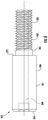
- a locking washer 400 is disposed around the first outer diameter portion 265 of the rotary joint spindle 250 and abuts an inboard end surface 272 of the second outer diameter portion 266 of the rotary joint spindle 250. Also, the locking washer 400 is positioned in an annular groove 273 formed in the outboard end 192 of the spindle 180 at the outboard end of the spindle air passage 210. The locking washer 400 is provided between the spindle 180 and the rotary joint spindle 250 to provide a seal at an interface of the spindle air passage 210 and the rotary joint spindle 250.
- the locking washer 400 seals the interface between the spindle air passage 210 and the rotary joint spindle 250 at the outboard end of the spindle air passage 210 and the first outer diameter portion 265 of the rotary joint spindle 250 so that pressurized air directed through the spindle air passage 210 is transferred to the rotary joint spindle air passage 260, and vice versa.
- the locking washer 400 may be formed from a suitable metal such as aluminum or steel.
- the locking washer 400 is a generally annular member.
- the locking washer 400 comprises an inner ring 405.
- the inner ring 405 comprises a first surface 410 and a second surface 415.
- the locking washer 400 is of a hollow star shape.
- a plurality of teeth 420 are attached to the inner ring 405 and are circumferentially spaced apart therearound.
- the teeth 420 comprise edges 425, 430 which allow the locking washer 400 to engage oppositely facing surfaces provided on the spindle 180 and the rotary joint spindle 250, respectively.
- the teeth 420 engage the inboard end surface 272 of the second outer diameter portion 266 and an outboard facing surface 273A of the spindle groove 273 to prevent vibration(s) or other forces from separating the spindle 180 and the rotary joint spindle 250 .
- the locking washer 400 has an opening 435 formed therein which extends from the first surface 410 to the second surface 415 so that the locking washer 400 can be disposed around the first outer diameter portion 265 of the rotary joint spindle 250.
- the opening 435 is defined by a sealing portion 440 of the locking washer 400.
- the sealing portion 440 comprises an elastomeric material.
- the elastomeric materials are lubricant and moisture resistant.
- the elastomeric material is bonded to the inner ring 405 via molding or another suitable process.
- the elastomeric material may be bonded to the inner ring 405 in such a manner that an annular portion of the first surface 410 and the second surface 415 is covered by the elastomeric material.
- the elastomeric material is utilized to provide a seal which seals the interface between the spindle air passage 210 and the rotary joint spindle 250 at the outboard end of the spindle air passage 210 and the first outer diameter portion 265 of the rotary joint spindle 250.
- the elastomeric material on the first surface 410 seals against a portion of the inboard end surface 272 of the second outer diameter portion 266 and the elastomeric material on the second surface 415 seals against a portion of the outboard facing surface 273A of the spindle groove 273 to prevent pressurized air from leaking between the spindle air passage 210 and the rotary joint spindle 250.
- the locking washer 400 has been described for use in helping to maintain the position of two non-rotating members of a tire inflation system relative to each other and helping seal an interface therebetween, it should be appreciated that the locking washer 400 may be utilized in other applications (not depicted). For example, the locking washer 400 may be utilized in a similar manner in a hydraulic system or another like system utilized to transfer a pressurized fluid.
- the locking washer 400 may be replaced with a non-locking sealing washer (not depicted).
- the rotary joint assembly 200 does not comprise the locking washer 400, and instead the rotary joint assembly 200 comprises a Loctite® Dri-Loc® Threadlocker (not depicted), a product of the Henkel Corporation who's United States headquarters is located at One Henkel Way, Rocky Hill, CT 06067.
- the Loctite® Dri-Loc® Threadlocker is located on the threaded portion 268 of the rotary joint spindle 250.
- the rotary joint assembly 200 does not comprise the locking washer 400, and instead the rotary joint assembly 200 comprises a thread sealant (not depicted) located on the threaded portion 268 of the rotary joint spindle 250.
- the rotary joint assembly 200 comprises the locking washer 400, the Loctite® Dri-Loc® Threadlocker, and the thread sealant.
- the rotary joint assembly 200 comprises the non-locking sealing washer, the Loctite® Dri-Loc® Threadlocker, and the thread sealant.
- the rotary joint assembly 200 comprises the locking washer 400 and the Loctite® Dri-Loc® Threadlocker.
- the rotary joint assembly 200 comprises the non-locking sealing washer and the Loctite® Dri-Loc® Threadlocker. In still another embodiment the rotary joint assembly 200 comprises the locking washer 400 and the thread sealant. In an additional embodiment, the rotary joint assembly 200 comprises the non-locking washer and the thread sealant.
- the rotary joint assembly 200 may also comprise an annular locating washer 275 disposed around the second outer diameter portion 266 of the rotary joint spindle 250.
- the locating washer 275 may be utilized to secure the location of a rotary oil seal 274 disposed around the second outer diameter portion 266 of the rotary joint spindle 250.
- a snap ring 278 disposed around the second outer diameter portion 266 of the rotary joint spindle 250 may also be utilized to ensure the location of the rotary oil seal 274.
- the rotary joint assembly 200 further comprises a rotary air seal 280 disposed around the second outer diameter portion 266 of the rotary joint spindle 250.
- a snap ring 282 disposed around the second outer diameter portion 266 of the rotary joint spindle 250 may be utilized to ensure the location of the rotary air seal 280.
- the snap rings 278 and 282 may be secured in grooves 285 formed in an inner surface 286 of a rotary joint air collector ring 284.
- the rotary oil seal 274 and the rotary air seal 280 help prevent, or reduce, oil leakage and air leakage, respectively, into an annular vent chamber 276A defined between the inner surface 286 of the rotary joint air collector ring 284 and the second outer diameter portion 266 of the rotary joint spindle.
- An area between the locating washer 275 and the outboard end 192 of the spindle 180 contains a lubricant (not depicted) utilized to lubricate the bearing 235.
- a lubricant utilized to lubricate the bearing 235.
- pressurized air from the tire inflation system 12 does not enter the area between the locating washer 275 and the outboard end 192 of the spindle 180.
- the bearing 235 seal is provided inboard of the bearing 235.
- the rotary joint air collector ring 284 is generally annular and rotatably disposed about the rotary joint spindle 250.
- the rotary oil seal 274 and the rotary air seal 280 both seal against the inner surface 286 of the rotary joint air collector ring 284.
- an inboard surface 288 of the rotary joint air collector ring 284 abuts an outboard surface 290 of the hub 230.
- the rotary joint air collector ring 284 comprises a first portion 291 connected to a second portion 292 by a third portion 293.
- the third portion 293 may be a rib-like member including an arcuate or straight geometry.
- the first portion 291 is generally cylindrical in shape and comprises an outboard cap 279.
- the first portion 291 comprises a first inner surface 286 and a second inner surface 286A, where the first inner surface 286 is of a greater diameter than the second inner surface 286A.
- the first inner surface 286 may comprise the annular grooves 285 for securing the snap rings 278 and 282 to the rotary joint air collector ring 284.
- the first inner surface 286 may also comprise an annular groove 287 for securing the locating washer 275 to the rotary joint air collector ring 284.
- the second portion 292 is generally annular in shape and comprises fastener holes 310.
- An outer diameter 294 of the second portion 292 is greater than an outer diameter 295 of the first portion 291.
- the first inner surface 286 and the second inner surface 286A define air chamber 276.
- the air chamber 276 is in fluid connection with a first air channel 296.
- the first air channel 296 comprises a first conduit 296A, a second conduit 296B, and a third conduit 296C.
- the first conduit 296A is oriented in the first portion 291 and comprises a longitudinal axis generally oriented perpendicular to the longitudinal axis of the rotary joint spindle 250.
- the first conduit 296A is connected to and in fluid communication with air chamber 276 and second conduit 296B.
- the second conduit 296B is disposed through the third portion 293 and comprises a longitudinal axis disposed obliquely to the longitudinal axis of the first portion 291.
- the second conduit 296B is connected to and in fluid communication with the first conduit 296A and the third conduit 296C.
- the third conduit 296C is disposed in the second portion 292 and comprises a longitudinal axis oriented parallel to the longitudinal axis of the first conduit 296A.
- the third conduit 296C intersects and is in fluid connection with a port 297.
- the port 297 comprises a port member 297A and a port opening 297B.
- the port member 297A is coupled to the outer diameter 294 of the second portion 292 of the rotary joint air collector ring 284.
- the port member 297A and the rotary joint air collector ring 284 comprise a unitary module.
- the port member 297A may comprise a longitudinal axis parallel to the longitudinal axis of the second portion 292.
- the port member 297A extends beyond an outboard surface 315 of the second portion 292.
- the port opening 297B is in fluid communication with the third conduit 296C and is capable of connecting in fluid communication with a fluid-transfer module (not depicted) or a wheel valve assembly.
- the port opening 297B is capable of coupling with a tire air hose (not depicted).
- the second air channel 298 intersects and is in fluid communication with the vent chamber 276A and comprises a first vent passage 298A, a second vent passage 298B, and a third vent passage 298C.
- the first vent passage 298A is oriented in the first portion 291 and comprises a longitudinal axis generally oriented perpendicular to the longitudinal axis of the rotary joint spindle 250.
- the first vent passage 298A is connected to and in fluid communication with the vent chamber 276A and the second vent passage 298B.
- the second vent passage 298B is disposed through the third portion 293 and comprises a longitudinal axis disposed obliquely to the longitudinal axis of the first portion 291.
- the second vent passage 298B is connected to and in fluid communication with the first vent passage 298A and the third vent passage 298C.
- the third vent passage 298C is disposed in the second portion 292 and comprises a longitudinal axis oriented parallel to the longitudinal axis of the first vent passage 298A.
- the third vent passage 298C is connected to and in fluid communication with the second vent passage 298B and a vent opening 299 disposed in the outer diameter 294 of the second portion 292 of the rotary joint air collector ring 284.
- the rotary joint air collector ring 284 allows compressed air that escapes via the rotary air seal 280 to vent to the atmosphere by way of the vent opening 299, and the rotary oil seal 274 prevents compressed air from entering the hub 230.
- third portion 293 comprises arms 293A and 293B. It must be noted that third portion 293 may comprise any component that defines, contains, or abuts the air channels 296 and 298, connected to and in fluid communication with the air chamber 276 and the vent chamber 276A, the port 297 and the vent opening 299. In an embodiment (not depicted), the third portion 293 comprises a conical shape connecting the first portion 291 and the second portion 292. In an embodiment, the first and second air channels 296 and 298 comprise diameters equal to or greater than the diameter of the rotary joint spindle air passage 260. In another embodiment, the first and second air channels 296 and 298 comprise diameters less than or equal to the diameter of the rotary joint spindle air passage 260.
- the rotary joint air collector ring 284 and the rotary joint spindle 250 are not in direct contact.
- the rotary joint air collector ring 284 and the rotary joint spindle 250 are in fluid communication via the air chamber 276.
- the first air channel 296 is in fluid communication with a wheel valve (not depicted) or a tire (not depicted) by way of the port 297 coupled with an air conduit (not depicted).
- the rotary joint air collector ring 284 may be manufactured out of any material, having the necessary characteristics to enable its function in the rotary joint assembly 200 for a variable length of time, including but not limited to aluminum, aluminum alloy, steel, iron, titanium, carbon fiber, polymer materials or any combination thereof.
- the rotary joint air collector ring 284 may be manufactured using additive manufacturing processes, machining, casting, forging, any other suitable method, or a combination of any suitable methods.
- the first portion 291, the second portion 292, and the third portion 293 of the rotary joint air collector ring 284 are machined from a billet.
- the first and second air channels 296 and 298 may be produced by drilling through the first portion 291, second portion 292, and third portion 293.
- the holes breach the outer diameter of the first portion 295, the outer diameter 294 of the second portion 292, the outer surface of the third portion 293, or the inboard surface of the rotary joint air collector ring 288, the holes may be welded closed, plugged, or a combination thereof.
- the rotary joint air collector ring 284 is coupled to a hub cap 300 by one or more fasteners (not depicted), where the fasteners (not depicted) are of a suitable length to attach both the hub cap 300 and the rotary joint air collector ring 284 to the hub 230.
- the hub cap 300 may partially house the rotary joint air collector ring 284.
- the hub cap 300 and the rotary joint air collector ring 284 rotate with the hub 230.
- the hub cap 300 may be of any configuration or production.
- the hub cap 300 comprises a pressure relief mechanism (not depicted) to relieve any pressure increase adjacent bearing 235.
- the pressure relief mechanism may be located in end portion 305 of the hub cap 300, and may be of the rubber plug or diaphragm variety.
Landscapes
- Engineering & Computer Science (AREA)
- Mechanical Engineering (AREA)
- Joints Allowing Movement (AREA)
- Tires In General (AREA)
Applications Claiming Priority (2)
| Application Number | Priority Date | Filing Date | Title |
|---|---|---|---|
| US201562174627P | 2015-06-12 | 2015-06-12 | |
| US201562174988P | 2015-06-12 | 2015-06-12 |
Publications (3)
| Publication Number | Publication Date |
|---|---|
| EP3103662A1 true EP3103662A1 (de) | 2016-12-14 |
| EP3103662A8 EP3103662A8 (de) | 2017-02-22 |
| EP3103662B1 EP3103662B1 (de) | 2020-08-05 |
Family
ID=56119385
Family Applications (1)
| Application Number | Title | Priority Date | Filing Date |
|---|---|---|---|
| EP16174034.5A Active EP3103662B1 (de) | 2015-06-12 | 2016-06-10 | Drehverbindungs-luftsammlerring und damit hergestelltes reifenaufpumpsystem |
Country Status (2)
| Country | Link |
|---|---|
| US (1) | US10562357B2 (de) |
| EP (1) | EP3103662B1 (de) |
Cited By (2)
| Publication number | Priority date | Publication date | Assignee | Title |
|---|---|---|---|---|
| CN113733820A (zh) * | 2021-11-05 | 2021-12-03 | 比亚迪股份有限公司 | 旋转结构、轮边结构和车辆 |
| IT202000024172A1 (it) * | 2020-10-14 | 2022-04-14 | Cnh Ind Italia Spa | Mozzo ruota di un veicolo agricolo o da lavoro |
Families Citing this family (6)
| Publication number | Priority date | Publication date | Assignee | Title |
|---|---|---|---|---|
| US10556469B2 (en) * | 2015-09-17 | 2020-02-11 | Dana Heavy Vehicle Systems Group, Llc | Hub cap assembly and a wheel end assembly for a tire inflation system |
| US10807413B2 (en) * | 2017-02-02 | 2020-10-20 | Dana Heavy Vehicle Systems Group, Llc | Front axle wheel assembly and the tire inflation system made therewith |
| US11077726B2 (en) | 2017-06-30 | 2021-08-03 | Dana Automotive Systems Group, Llc | Front axle rotary joint assembly and the tire inflation system made therewith |
| US11951779B2 (en) | 2018-01-17 | 2024-04-09 | Illinois Tool Works Inc. | System for transmitting control pressures and/or working pressures |
| DE102018100955B4 (de) * | 2018-01-17 | 2024-01-18 | Illinois Tool Works Inc. | System zum übertragen von steuer- und/oder arbeitsdrücken |
| US11845347B2 (en) | 2021-05-12 | 2023-12-19 | David Alan Copeland | Precision charging control of an untethered vehicle with a modular vehicle charging roadway |
Citations (4)
| Publication number | Priority date | Publication date | Assignee | Title |
|---|---|---|---|---|
| US2156841A (en) * | 1938-04-09 | 1939-05-02 | Walter H Davis | Tire pressure controlling apparatus |
| US2242207A (en) * | 1939-03-01 | 1941-05-20 | Aidco Automatic Inflator And D | Air distributing head for tire inflation devices |
| US7975739B1 (en) * | 1998-05-14 | 2011-07-12 | Airgo Ip, Llc | Rotary union assembly for use in air pressure inflation systems for tractor trailer tires |
| US20120024445A1 (en) * | 2010-07-30 | 2012-02-02 | Hendrickson Usa, L.L.C. | Constant pressure pneumatic balancing tire inflation system |
Family Cites Families (110)
| Publication number | Priority date | Publication date | Assignee | Title |
|---|---|---|---|---|
| US1112596A (en) | 1913-05-28 | 1914-10-06 | Louis Burggraf Jr | Means for tire inflation. |
| US1772212A (en) | 1927-08-26 | 1930-08-05 | Daneel Richard Hurtley | Means for inflating pneumatic tires |
| US2236235A (en) | 1938-12-01 | 1941-03-25 | Illinois Tool Works | Fastener means and method of making same |
| US2715430A (en) | 1952-08-02 | 1955-08-16 | Sun Oil Co | Apparatus for controlling pressure in pneumatic tires |
| US3114579A (en) | 1962-05-28 | 1963-12-17 | Chicago Rawhide Mfg Co | Hub cap plug valve and assembly |
| US3259404A (en) | 1963-10-23 | 1966-07-05 | Parker Hannifin Corp | Sealed joint and gasket therefor |
| US3276503A (en) | 1965-01-21 | 1966-10-04 | Scovill Manufacturing Co | Tire pressure maintenance system |
| US3829104A (en) | 1972-03-20 | 1974-08-13 | M Green | Annular seal |
| US3855383A (en) | 1972-04-24 | 1974-12-17 | Co Essdee Prod | Sealing lock washer and method of manufacturing |
| US3879001A (en) | 1973-01-02 | 1975-04-22 | Garlock Inc | Tape wrapping method, apparatus, and article |
| US3858950A (en) | 1973-02-26 | 1975-01-07 | Timken Co | Sealed bearing |
| US4154279A (en) | 1975-03-25 | 1979-05-15 | Yasuo Tsuruta | Apparatus for remotely controlling the internal pressure of a pneumatic tire |
| US4073540A (en) | 1976-01-28 | 1978-02-14 | Chicago Rawhide Manufacturing Co. | Sealed hub cap and method |
| US4026183A (en) | 1976-05-17 | 1977-05-31 | Illinois Tool Works Inc. | Sealing washer |
| US4191389A (en) | 1977-10-26 | 1980-03-04 | Parker-Hannifin Corporation | Sealing washer |
| US4282949A (en) | 1979-10-29 | 1981-08-11 | General Motors Corporation | Hub locks for independently suspended wheels |
| US4251082A (en) | 1980-01-21 | 1981-02-17 | Caterpillar Tractor Co. | Joint seal having force transfer ring |
| US4470506A (en) | 1981-10-16 | 1984-09-11 | Am General Corporation | Automatic tire inflation system retrofitting kit |
| US4448461A (en) | 1982-03-16 | 1984-05-15 | The Timken Company | Self-venting seal |
| US4434833A (en) | 1982-04-21 | 1984-03-06 | Eaton Corporation | Axle wheel end assembly |
| US4492019A (en) | 1983-06-30 | 1985-01-08 | Rockwell International Corporation | Method of forming an axle |
| US4582107A (en) | 1984-07-26 | 1986-04-15 | The United States Of America As Represented By The Secretary Of The Army | Vehicle tire inflation-deflation mechanism |
| US4641698A (en) | 1984-11-08 | 1987-02-10 | Am General Corporation | Automated vehicle tire pressurization system |
| US5236028A (en) | 1985-07-08 | 1993-08-17 | Am General Corporation | Vehicle wheel end assembly |
| US4895199A (en) | 1986-07-31 | 1990-01-23 | Paccar Inc | Tire inflation and deflation valve |
| US4844138A (en) | 1986-09-01 | 1989-07-04 | Kabushiki Kaisha Tokai Rika Denki Seisakusho | Automobile tire pneumatic pressure controlling apparatus |
| US4834464A (en) | 1987-12-31 | 1989-05-30 | Cpr Systems Inc. | Magnetic wheel bearing cap |
| US4921258A (en) | 1988-08-08 | 1990-05-01 | Aeroquip Corporation | Adapter seal |
| US4883106A (en) | 1989-01-19 | 1989-11-28 | Eaton Corporation | Rotary wheel-end assembly for tire inflation system |
| US4932451A (en) | 1989-01-26 | 1990-06-12 | General Motors Corporation | Vehicle wheel end assembly with air passage |
| ES2082030T3 (es) | 1990-05-17 | 1996-03-16 | Equalaire Systems Inc | Sistema de control de aire para neumaticos de un vehiculo. |
| US5203391A (en) * | 1991-03-15 | 1993-04-20 | The Timken Company | Wheel mounting for tire pressure adjustment system |
| US5217137A (en) | 1991-04-22 | 1993-06-08 | Freudenberg-Nok General Partnership | Seal for an end cap |
| US5174839A (en) | 1991-07-05 | 1992-12-29 | Eaton Corporation | Drive axle sleeve and seal assembly |
| US5240039A (en) | 1991-12-19 | 1993-08-31 | Col-Ven S.A. | Rotor for adapting static elements to elements rotating around a shaft |
| US5328275A (en) | 1993-05-06 | 1994-07-12 | Stemco Inc. | Unitized wheel hub and bearing assembly |
| US5429167A (en) | 1993-08-13 | 1995-07-04 | Oshkosh Truck Corporation | Universal central tire inflation system for trailers |
| US5377736A (en) | 1993-11-18 | 1995-01-03 | Marks-Rms, Inc. | Driven axle vehicle inflation system |
| US5505525A (en) | 1994-01-10 | 1996-04-09 | Skf Usa Inc. | Hubcap and method of manufacturing the same |
| US5584949A (en) | 1994-05-06 | 1996-12-17 | Ingram; Anthony L. | Air inflation system for trailer axles |
| US5482358A (en) | 1994-08-25 | 1996-01-09 | Dual Dynamics | Vented plug for a hubcap |
| US5524904A (en) | 1994-11-10 | 1996-06-11 | Kelsey-Hayes Company | Lip seal for antilock braking system isolation valve and similar valves |
| US5538330A (en) | 1994-11-17 | 1996-07-23 | Wabash National Corporation | Axle vent |
| US5785390A (en) | 1995-01-31 | 1998-07-28 | Stemco Inc. | Vented hubcap |
| US5658053A (en) | 1995-03-24 | 1997-08-19 | Vencill; R. Lee | Shaft re-greasing hub |
| US5752746A (en) | 1995-12-15 | 1998-05-19 | Stemco Inc | Hubcap with vented closure |
| FR2750082A1 (fr) | 1996-06-25 | 1997-12-26 | Michelin & Cie | Ensemble moyeu et porte-moyeu pour vehicule equipe d'un systeme de gonflage centralise |
| US5769979A (en) | 1996-08-30 | 1998-06-23 | Equalaire Systems, Inc. | Rotary air connection for tire inflation system |
| US5868881A (en) | 1996-09-04 | 1999-02-09 | Equalaire Systems, Inc. | Rotary air coupling for tire inflation system |
| US5904427A (en) | 1996-11-04 | 1999-05-18 | Stemco Inc | Unitized wheel hub and bearing assembly with lubricant distributing vanes |
| US6290235B1 (en) | 1997-07-02 | 2001-09-18 | Parker-Hannifin Corporation | Sealing system for a reciprocating shaft |
| US5860708A (en) | 1997-07-11 | 1999-01-19 | Stemco Inc | Contaminant excluding hubcap vent plug |
| AT2364U1 (de) | 1997-09-09 | 1998-09-25 | Steyr Daimler Puch Ag | Radträger für kraftfahrzeug mit reifenfüllanlage |
| US5997005A (en) | 1997-10-24 | 1999-12-07 | Stemco Inc | Hub seal with machinable thrust ring |
| US8028732B1 (en) | 1998-05-14 | 2011-10-04 | Airgo Ip, Llc | Tire inflation system |
| US6938658B2 (en) | 2003-06-09 | 2005-09-06 | Airgo Ip, Llc | Expandable spindle plug assembly for use with automatic tire inflation systems |
| US20050133134A1 (en) | 2001-11-13 | 2005-06-23 | Airgo Ip, Llc | Rotary union assembly for use in air pressure inflation systems for tractor trailer tires |
| US6158743A (en) | 1998-06-22 | 2000-12-12 | Stemco Inc | Hub seal with low installation load and rotation prevention structure |
| US6145558A (en) | 1998-12-10 | 2000-11-14 | Case Corporation | Seal arrangement for a central tire inflation system |
| WO2001002196A1 (en) | 1999-07-02 | 2001-01-11 | Pressure Guard, Inc. | On-axle tire inflation system |
| US6244316B1 (en) | 1999-07-16 | 2001-06-12 | Vehicle Inflation Technologies, Inc | Vehicle tire inflation system |
| US6260595B1 (en) | 1999-08-04 | 2001-07-17 | Meritor Heavy Vehicle Systems, Llc | Unitized hub cap |
| AUPQ208599A0 (en) | 1999-08-06 | 1999-08-26 | Neumann Steel Pty Limited | A hub cap for a wheel bearing |
| US6145559A (en) | 1999-09-03 | 2000-11-14 | Accessio, Ltd. | Axle and hub assembly for automatic tire inflation pressurization system |
| DE19950191C1 (de) | 1999-10-19 | 2001-05-10 | Tigges & Winckel Bonumwerke | Reifendruckregelanlage |
| US6283186B1 (en) | 1999-11-23 | 2001-09-04 | Dana Corporation | Tire inflation system for live spindle wheel end |
| US6273519B1 (en) | 2000-02-02 | 2001-08-14 | Eric Tsou | Oil hub cup |
| US6325124B1 (en) | 2000-02-03 | 2001-12-04 | Col-Ven S.A. | Pneumatic rotary wheel coupling |
| US6269691B1 (en) | 2000-03-17 | 2001-08-07 | Equalaire Systems, Inc | Automatic tire inflation system with booster pump |
| US6435238B1 (en) | 2001-03-22 | 2002-08-20 | Equalaire Systems, Inc. | Combination of an automatic tire inflation system and anti-locking braking system |
| US6334791B1 (en) | 2000-07-12 | 2002-01-01 | Min-Hua Yeh | Load connector |
| US6447072B1 (en) | 2001-01-25 | 2002-09-10 | Lawrence N. Johnson | Oil-bath wheel hub |
| US6394159B1 (en) | 2001-01-26 | 2002-05-28 | Meritor Heavy Vehicle Technology, Llc | Hub cap filter for tire inflation system |
| DE60206430T2 (de) | 2001-02-22 | 2006-06-29 | ArvinMeritor Technology, LLC, Troy | Fahrzeugrad mit Endanordnung |
| US6575028B2 (en) | 2001-03-12 | 2003-06-10 | Col-Ven S.A. | Auto-cleaning oil-gauge for axle-ends of vehicles |
| WO2003037662A1 (en) | 2001-10-31 | 2003-05-08 | Stemco Llc | Tire pressure monitoring system |
| US6698482B2 (en) | 2002-07-01 | 2004-03-02 | Equalaire Systems, Inc. | Rotary air connection with bearing for tire inflation system |
| AU2004220148C1 (en) | 2003-03-06 | 2009-01-22 | Hendrickson International Corporation | Tire inflation system and method |
| US7207365B2 (en) * | 2003-03-06 | 2007-04-24 | Nelson Christopher A | Central tire inflation system rotary air union |
| US6783191B1 (en) | 2003-03-11 | 2004-08-31 | Dana Corporation | Axle hubcap vent |
| WO2005042293A1 (en) | 2003-10-03 | 2005-05-12 | Leblanc James C Sr | Wheel unit for automotive vehicles |
| US7185688B2 (en) | 2004-01-27 | 2007-03-06 | Arvinmeritor Technology, Llc | Central tire inflation system for drive axle |
| US7302979B2 (en) | 2005-03-16 | 2007-12-04 | Dana Corporation | Vehicle tire inflation system and sensor and method of use |
| US7306020B2 (en) | 2005-04-19 | 2007-12-11 | Dana Corporation | Tire inflation system and wheel sensor and method of use |
| EP1738936B1 (de) * | 2005-06-28 | 2008-11-05 | Aktiebolaget SKF | Lagervorrichtung für eine Radnabe geeignet zur Druckluftzufuhr in einem Reifen eines Kraftfahrzeugrades |
| JP4529899B2 (ja) | 2005-12-28 | 2010-08-25 | トヨタ自動車株式会社 | 空気供給装置 |
| DE102006006143A1 (de) | 2006-02-10 | 2007-08-23 | Schaeffler Kg | Dichtungsanordnung für eine Reifendruck-Reguliereinrichtung |
| US7686313B2 (en) | 2006-04-26 | 2010-03-30 | The Timken Company | Wheel end vented through sensor cable |
| US7896045B2 (en) | 2006-11-13 | 2011-03-01 | The Board Of Regents For Oklahoma State University | Apparatus for delivering air through powered axle assemblies |
| DE102007005765A1 (de) | 2007-02-06 | 2008-08-14 | Fereshteh Saadat | Radachse und Antriebs- oder Gelenkwelle |
| DE102007058036A1 (de) | 2007-02-06 | 2008-08-28 | Fereshteh Saadat | Fahrzeugfelge mit zentralem Ventil |
| US8051940B2 (en) | 2008-03-13 | 2011-11-08 | Dana Heavy Vehicle Systems Group, Llc | Hydraulic assist wheel end |
| US7963159B2 (en) | 2008-03-25 | 2011-06-21 | Airgo Ip, Llc | Inflation system for tires |
| US8069890B2 (en) | 2008-04-25 | 2011-12-06 | Hutchinson S.A. | Hub bore mounted central tire inflation valve system |
| ATE539904T1 (de) * | 2008-05-16 | 2012-01-15 | Hendrickson Usa Llc | Integrierte drehdurchführung und nabenkappe |
| US7690412B1 (en) | 2008-11-04 | 2010-04-06 | Arvinmeritor Technology, Llc | Drive axle with air passage for tire inflation system |
| US8002237B2 (en) | 2008-11-12 | 2011-08-23 | Velan Inc. | Seat arrangement with cavity pressure relief for a ball valve |
| US7931061B2 (en) | 2008-12-15 | 2011-04-26 | Arvinmeritor Technology, Llc | Tire inflation system with integrated wheel seal |
| US8915274B2 (en) | 2009-01-22 | 2014-12-23 | Arvinmeritor Technology, Llc | Spindle for controlling wheel end endplay and preload |
| MX359133B (es) | 2010-06-21 | 2018-09-17 | Equalaire Systems Inc | Conexión de aire giratoria con válvula central para sistema de inflación de neumáticos. |
| US8746305B2 (en) | 2011-06-15 | 2014-06-10 | Arvinmeritor Technology, Llc | Rotating seal assembly for tire inflation system |
| US9221308B2 (en) * | 2012-02-06 | 2015-12-29 | Stemco Lp | Central tire inflation system rotary air union |
| MX339079B (es) | 2012-02-07 | 2016-05-10 | Stemco Lp | Indicador de flujo proporcional inalambrico para el sistema de presion de neumaticos. |
| US8997336B2 (en) | 2012-09-10 | 2015-04-07 | Renewable Energy Holdings, Llc | Air-tight and water-tight electrical bonding device |
| US9387731B2 (en) | 2012-09-19 | 2016-07-12 | Stemco Lp | Central tire inflation system pressure regulator |
| US9290044B2 (en) | 2012-11-30 | 2016-03-22 | Cimmaster Inc. | Oil hub cap |
| BR112015023305A2 (pt) | 2013-03-15 | 2018-12-11 | Dana Heavy Vehicle Sys Group | montagem |
| USD749482S1 (en) | 2013-08-21 | 2016-02-16 | Stemco Lp | Hub cap |
| US9352621B2 (en) | 2014-07-15 | 2016-05-31 | Arvinmeritor Technology, Llc | Tire inflation system having a pressure relief valve |
| US10556469B2 (en) * | 2015-09-17 | 2020-02-11 | Dana Heavy Vehicle Systems Group, Llc | Hub cap assembly and a wheel end assembly for a tire inflation system |
-
2016
- 2016-06-10 EP EP16174034.5A patent/EP3103662B1/de active Active
- 2016-06-10 US US15/178,690 patent/US10562357B2/en not_active Expired - Fee Related
Patent Citations (4)
| Publication number | Priority date | Publication date | Assignee | Title |
|---|---|---|---|---|
| US2156841A (en) * | 1938-04-09 | 1939-05-02 | Walter H Davis | Tire pressure controlling apparatus |
| US2242207A (en) * | 1939-03-01 | 1941-05-20 | Aidco Automatic Inflator And D | Air distributing head for tire inflation devices |
| US7975739B1 (en) * | 1998-05-14 | 2011-07-12 | Airgo Ip, Llc | Rotary union assembly for use in air pressure inflation systems for tractor trailer tires |
| US20120024445A1 (en) * | 2010-07-30 | 2012-02-02 | Hendrickson Usa, L.L.C. | Constant pressure pneumatic balancing tire inflation system |
Cited By (4)
| Publication number | Priority date | Publication date | Assignee | Title |
|---|---|---|---|---|
| IT202000024172A1 (it) * | 2020-10-14 | 2022-04-14 | Cnh Ind Italia Spa | Mozzo ruota di un veicolo agricolo o da lavoro |
| EP3985272A1 (de) * | 2020-10-14 | 2022-04-20 | CNH Industrial Italia S.p.A. | Radnabe für ein landwirtschafts- oder arbeitsfahrzeug |
| CN113733820A (zh) * | 2021-11-05 | 2021-12-03 | 比亚迪股份有限公司 | 旋转结构、轮边结构和车辆 |
| CN113733820B (zh) * | 2021-11-05 | 2022-04-15 | 比亚迪股份有限公司 | 旋转结构、轮边结构和车辆 |
Also Published As
| Publication number | Publication date |
|---|---|
| EP3103662A8 (de) | 2017-02-22 |
| US20160361957A1 (en) | 2016-12-15 |
| US10562357B2 (en) | 2020-02-18 |
| EP3103662B1 (de) | 2020-08-05 |
Similar Documents
| Publication | Publication Date | Title |
|---|---|---|
| EP3103662B1 (de) | Drehverbindungs-luftsammlerring und damit hergestelltes reifenaufpumpsystem | |
| US10556469B2 (en) | Hub cap assembly and a wheel end assembly for a tire inflation system | |
| EP2969600B1 (de) | Anordnung | |
| EP2836376B1 (de) | Reifenfüllanlage | |
| EP2535208B1 (de) | Rotierende Dichtungsanordnung für Reifenfüllsystem | |
| EP2974892B1 (de) | Reifendruckregelanlage mit überdruckventil | |
| EP2960082B1 (de) | Reifenaufpumpsystem mit einer dichtung | |
| US20090084481A1 (en) | Tire inflation control method and apparatus | |
| EP2848435B1 (de) | Reifenfüllsystem mit Drehkupplung | |
| US20150075688A1 (en) | Tire Inflation System with a Passage for Routing Pressurized Gas | |
| US20100225157A1 (en) | Spindle with hydraulic passage arrangement and method of manufacture | |
| US10807413B2 (en) | Front axle wheel assembly and the tire inflation system made therewith | |
| RU2761312C2 (ru) | Вращающееся соединение и система регулирования давления для шин | |
| EP3157765B1 (de) | Drehverbindungsanordnung | |
| US20200094621A1 (en) | Axle assembly and the tire inflation system made therewith | |
| US11034194B2 (en) | Wheel end assembly for a tire inflation system and the tire inflation system made therewith | |
| US11292300B2 (en) | Ported wheel hub assembly and the tire inflation system made therewith | |
| EP3331710B1 (de) | Drehkupplungsanordnung für ein reifenfüllsystem | |
| US20190001762A1 (en) | Front Axle Rotary Joint Assembly And The Tire Inflation System Made Therewith | |
| US11345193B2 (en) | Wheel end assembly with external rotary joint and rotary joint venting mechanism | |
| US10556470B2 (en) | Rotary joint assembly for a tire pressure management system | |
| KR102550565B1 (ko) | 구면 평 베어링, 구동 가능한 조향 차축, 및 이동형 굴삭기 |
Legal Events
| Date | Code | Title | Description |
|---|---|---|---|
| PUAI | Public reference made under article 153(3) epc to a published international application that has entered the european phase |
Free format text: ORIGINAL CODE: 0009012 |
|
| STAA | Information on the status of an ep patent application or granted ep patent |
Free format text: STATUS: REQUEST FOR EXAMINATION WAS MADE |
|
| 17P | Request for examination filed |
Effective date: 20160610 |
|
| AK | Designated contracting states |
Kind code of ref document: A1 Designated state(s): AL AT BE BG CH CY CZ DE DK EE ES FI FR GB GR HR HU IE IS IT LI LT LU LV MC MK MT NL NO PL PT RO RS SE SI SK SM TR |
|
| AX | Request for extension of the european patent |
Extension state: BA ME |
|
| RIN1 | Information on inventor provided before grant (corrected) |
Inventor name: BURKE, DOUGLAS C. Inventor name: FOOR, WILLIAM J. Inventor name: LEWARK, CHRISTOPHER P. |
|
| RBV | Designated contracting states (corrected) |
Designated state(s): AL AT BE BG CH CY CZ DE DK EE ES FI FR GB GR HR HU IE IS IT LI LT LU LV MC MK MT NL NO PL PT RO RS SE SI SK SM TR |
|
| STAA | Information on the status of an ep patent application or granted ep patent |
Free format text: STATUS: EXAMINATION IS IN PROGRESS |
|
| 17Q | First examination report despatched |
Effective date: 20191017 |
|
| RIC1 | Information provided on ipc code assigned before grant |
Ipc: B60B 27/00 20060101ALI20191217BHEP Ipc: B60C 23/00 20060101AFI20191217BHEP |
|
| GRAP | Despatch of communication of intention to grant a patent |
Free format text: ORIGINAL CODE: EPIDOSNIGR1 |
|
| STAA | Information on the status of an ep patent application or granted ep patent |
Free format text: STATUS: GRANT OF PATENT IS INTENDED |
|
| INTG | Intention to grant announced |
Effective date: 20200221 |
|
| RIN1 | Information on inventor provided before grant (corrected) |
Inventor name: LEWARK, CHRISTOPHER P. Inventor name: BURKE, DOUGLAS C. Inventor name: FOOR, WILLIAM J. |
|
| GRAS | Grant fee paid |
Free format text: ORIGINAL CODE: EPIDOSNIGR3 |
|
| GRAA | (expected) grant |
Free format text: ORIGINAL CODE: 0009210 |
|
| STAA | Information on the status of an ep patent application or granted ep patent |
Free format text: STATUS: THE PATENT HAS BEEN GRANTED |
|
| AK | Designated contracting states |
Kind code of ref document: B1 Designated state(s): AL AT BE BG CH CY CZ DE DK EE ES FI FR GB GR HR HU IE IS IT LI LT LU LV MC MK MT NL NO PL PT RO RS SE SI SK SM TR |
|
| REG | Reference to a national code |
Ref country code: GB Ref legal event code: FG4D |
|
| REG | Reference to a national code |
Ref country code: CH Ref legal event code: EP |
|
| REG | Reference to a national code |
Ref country code: AT Ref legal event code: REF Ref document number: 1298226 Country of ref document: AT Kind code of ref document: T Effective date: 20200815 |
|
| REG | Reference to a national code |
Ref country code: DE Ref legal event code: R096 Ref document number: 602016041197 Country of ref document: DE |
|
| REG | Reference to a national code |
Ref country code: IE Ref legal event code: FG4D |
|
| REG | Reference to a national code |
Ref country code: LT Ref legal event code: MG4D |
|
| REG | Reference to a national code |
Ref country code: NL Ref legal event code: MP Effective date: 20200805 |
|
| REG | Reference to a national code |
Ref country code: AT Ref legal event code: MK05 Ref document number: 1298226 Country of ref document: AT Kind code of ref document: T Effective date: 20200805 |
|
| PG25 | Lapsed in a contracting state [announced via postgrant information from national office to epo] |
Ref country code: LT Free format text: LAPSE BECAUSE OF FAILURE TO SUBMIT A TRANSLATION OF THE DESCRIPTION OR TO PAY THE FEE WITHIN THE PRESCRIBED TIME-LIMIT Effective date: 20200805 Ref country code: BG Free format text: LAPSE BECAUSE OF FAILURE TO SUBMIT A TRANSLATION OF THE DESCRIPTION OR TO PAY THE FEE WITHIN THE PRESCRIBED TIME-LIMIT Effective date: 20201105 Ref country code: NO Free format text: LAPSE BECAUSE OF FAILURE TO SUBMIT A TRANSLATION OF THE DESCRIPTION OR TO PAY THE FEE WITHIN THE PRESCRIBED TIME-LIMIT Effective date: 20201105 Ref country code: GR Free format text: LAPSE BECAUSE OF FAILURE TO SUBMIT A TRANSLATION OF THE DESCRIPTION OR TO PAY THE FEE WITHIN THE PRESCRIBED TIME-LIMIT Effective date: 20201106 Ref country code: ES Free format text: LAPSE BECAUSE OF FAILURE TO SUBMIT A TRANSLATION OF THE DESCRIPTION OR TO PAY THE FEE WITHIN THE PRESCRIBED TIME-LIMIT Effective date: 20200805 Ref country code: SE Free format text: LAPSE BECAUSE OF FAILURE TO SUBMIT A TRANSLATION OF THE DESCRIPTION OR TO PAY THE FEE WITHIN THE PRESCRIBED TIME-LIMIT Effective date: 20200805 Ref country code: AT Free format text: LAPSE BECAUSE OF FAILURE TO SUBMIT A TRANSLATION OF THE DESCRIPTION OR TO PAY THE FEE WITHIN THE PRESCRIBED TIME-LIMIT Effective date: 20200805 Ref country code: PT Free format text: LAPSE BECAUSE OF FAILURE TO SUBMIT A TRANSLATION OF THE DESCRIPTION OR TO PAY THE FEE WITHIN THE PRESCRIBED TIME-LIMIT Effective date: 20201207 Ref country code: HR Free format text: LAPSE BECAUSE OF FAILURE TO SUBMIT A TRANSLATION OF THE DESCRIPTION OR TO PAY THE FEE WITHIN THE PRESCRIBED TIME-LIMIT Effective date: 20200805 Ref country code: FI Free format text: LAPSE BECAUSE OF FAILURE TO SUBMIT A TRANSLATION OF THE DESCRIPTION OR TO PAY THE FEE WITHIN THE PRESCRIBED TIME-LIMIT Effective date: 20200805 |
|
| PG25 | Lapsed in a contracting state [announced via postgrant information from national office to epo] |
Ref country code: RS Free format text: LAPSE BECAUSE OF FAILURE TO SUBMIT A TRANSLATION OF THE DESCRIPTION OR TO PAY THE FEE WITHIN THE PRESCRIBED TIME-LIMIT Effective date: 20200805 Ref country code: LV Free format text: LAPSE BECAUSE OF FAILURE TO SUBMIT A TRANSLATION OF THE DESCRIPTION OR TO PAY THE FEE WITHIN THE PRESCRIBED TIME-LIMIT Effective date: 20200805 Ref country code: NL Free format text: LAPSE BECAUSE OF FAILURE TO SUBMIT A TRANSLATION OF THE DESCRIPTION OR TO PAY THE FEE WITHIN THE PRESCRIBED TIME-LIMIT Effective date: 20200805 Ref country code: PL Free format text: LAPSE BECAUSE OF FAILURE TO SUBMIT A TRANSLATION OF THE DESCRIPTION OR TO PAY THE FEE WITHIN THE PRESCRIBED TIME-LIMIT Effective date: 20200805 Ref country code: IS Free format text: LAPSE BECAUSE OF FAILURE TO SUBMIT A TRANSLATION OF THE DESCRIPTION OR TO PAY THE FEE WITHIN THE PRESCRIBED TIME-LIMIT Effective date: 20201205 |
|
| PG25 | Lapsed in a contracting state [announced via postgrant information from national office to epo] |
Ref country code: EE Free format text: LAPSE BECAUSE OF FAILURE TO SUBMIT A TRANSLATION OF THE DESCRIPTION OR TO PAY THE FEE WITHIN THE PRESCRIBED TIME-LIMIT Effective date: 20200805 Ref country code: CZ Free format text: LAPSE BECAUSE OF FAILURE TO SUBMIT A TRANSLATION OF THE DESCRIPTION OR TO PAY THE FEE WITHIN THE PRESCRIBED TIME-LIMIT Effective date: 20200805 Ref country code: DK Free format text: LAPSE BECAUSE OF FAILURE TO SUBMIT A TRANSLATION OF THE DESCRIPTION OR TO PAY THE FEE WITHIN THE PRESCRIBED TIME-LIMIT Effective date: 20200805 Ref country code: RO Free format text: LAPSE BECAUSE OF FAILURE TO SUBMIT A TRANSLATION OF THE DESCRIPTION OR TO PAY THE FEE WITHIN THE PRESCRIBED TIME-LIMIT Effective date: 20200805 Ref country code: SM Free format text: LAPSE BECAUSE OF FAILURE TO SUBMIT A TRANSLATION OF THE DESCRIPTION OR TO PAY THE FEE WITHIN THE PRESCRIBED TIME-LIMIT Effective date: 20200805 |
|
| REG | Reference to a national code |
Ref country code: DE Ref legal event code: R097 Ref document number: 602016041197 Country of ref document: DE |
|
| PG25 | Lapsed in a contracting state [announced via postgrant information from national office to epo] |
Ref country code: AL Free format text: LAPSE BECAUSE OF FAILURE TO SUBMIT A TRANSLATION OF THE DESCRIPTION OR TO PAY THE FEE WITHIN THE PRESCRIBED TIME-LIMIT Effective date: 20200805 |
|
| PLBE | No opposition filed within time limit |
Free format text: ORIGINAL CODE: 0009261 |
|
| STAA | Information on the status of an ep patent application or granted ep patent |
Free format text: STATUS: NO OPPOSITION FILED WITHIN TIME LIMIT |
|
| PG25 | Lapsed in a contracting state [announced via postgrant information from national office to epo] |
Ref country code: SK Free format text: LAPSE BECAUSE OF FAILURE TO SUBMIT A TRANSLATION OF THE DESCRIPTION OR TO PAY THE FEE WITHIN THE PRESCRIBED TIME-LIMIT Effective date: 20200805 |
|
| 26N | No opposition filed |
Effective date: 20210507 |
|
| PG25 | Lapsed in a contracting state [announced via postgrant information from national office to epo] |
Ref country code: IT Free format text: LAPSE BECAUSE OF FAILURE TO SUBMIT A TRANSLATION OF THE DESCRIPTION OR TO PAY THE FEE WITHIN THE PRESCRIBED TIME-LIMIT Effective date: 20200805 |
|
| PG25 | Lapsed in a contracting state [announced via postgrant information from national office to epo] |
Ref country code: SI Free format text: LAPSE BECAUSE OF FAILURE TO SUBMIT A TRANSLATION OF THE DESCRIPTION OR TO PAY THE FEE WITHIN THE PRESCRIBED TIME-LIMIT Effective date: 20200805 |
|
| PG25 | Lapsed in a contracting state [announced via postgrant information from national office to epo] |
Ref country code: MC Free format text: LAPSE BECAUSE OF FAILURE TO SUBMIT A TRANSLATION OF THE DESCRIPTION OR TO PAY THE FEE WITHIN THE PRESCRIBED TIME-LIMIT Effective date: 20200805 |
|
| REG | Reference to a national code |
Ref country code: CH Ref legal event code: PL |
|
| GBPC | Gb: european patent ceased through non-payment of renewal fee |
Effective date: 20210610 |
|
| REG | Reference to a national code |
Ref country code: BE Ref legal event code: MM Effective date: 20210630 |
|
| PG25 | Lapsed in a contracting state [announced via postgrant information from national office to epo] |
Ref country code: LU Free format text: LAPSE BECAUSE OF NON-PAYMENT OF DUE FEES Effective date: 20210610 |
|
| PG25 | Lapsed in a contracting state [announced via postgrant information from national office to epo] |
Ref country code: LI Free format text: LAPSE BECAUSE OF NON-PAYMENT OF DUE FEES Effective date: 20210630 Ref country code: IE Free format text: LAPSE BECAUSE OF NON-PAYMENT OF DUE FEES Effective date: 20210610 Ref country code: GB Free format text: LAPSE BECAUSE OF NON-PAYMENT OF DUE FEES Effective date: 20210610 Ref country code: CH Free format text: LAPSE BECAUSE OF NON-PAYMENT OF DUE FEES Effective date: 20210630 |
|
| PG25 | Lapsed in a contracting state [announced via postgrant information from national office to epo] |
Ref country code: FR Free format text: LAPSE BECAUSE OF NON-PAYMENT OF DUE FEES Effective date: 20210630 |
|
| PG25 | Lapsed in a contracting state [announced via postgrant information from national office to epo] |
Ref country code: BE Free format text: LAPSE BECAUSE OF NON-PAYMENT OF DUE FEES Effective date: 20210630 |
|
| PGFP | Annual fee paid to national office [announced via postgrant information from national office to epo] |
Ref country code: DE Payment date: 20220518 Year of fee payment: 7 |
|
| PG25 | Lapsed in a contracting state [announced via postgrant information from national office to epo] |
Ref country code: HU Free format text: LAPSE BECAUSE OF FAILURE TO SUBMIT A TRANSLATION OF THE DESCRIPTION OR TO PAY THE FEE WITHIN THE PRESCRIBED TIME-LIMIT; INVALID AB INITIO Effective date: 20160610 |
|
| PG25 | Lapsed in a contracting state [announced via postgrant information from national office to epo] |
Ref country code: CY Free format text: LAPSE BECAUSE OF FAILURE TO SUBMIT A TRANSLATION OF THE DESCRIPTION OR TO PAY THE FEE WITHIN THE PRESCRIBED TIME-LIMIT Effective date: 20200805 |
|
| REG | Reference to a national code |
Ref country code: DE Ref legal event code: R119 Ref document number: 602016041197 Country of ref document: DE |
|
| PG25 | Lapsed in a contracting state [announced via postgrant information from national office to epo] |
Ref country code: MK Free format text: LAPSE BECAUSE OF FAILURE TO SUBMIT A TRANSLATION OF THE DESCRIPTION OR TO PAY THE FEE WITHIN THE PRESCRIBED TIME-LIMIT Effective date: 20200805 Ref country code: DE Free format text: LAPSE BECAUSE OF NON-PAYMENT OF DUE FEES Effective date: 20240103 |