EP3103543A1 - Filterelement und filtereinrichtung zur filtration gasförmiger fluide - Google Patents
Filterelement und filtereinrichtung zur filtration gasförmiger fluide Download PDFInfo
- Publication number
- EP3103543A1 EP3103543A1 EP16179925.9A EP16179925A EP3103543A1 EP 3103543 A1 EP3103543 A1 EP 3103543A1 EP 16179925 A EP16179925 A EP 16179925A EP 3103543 A1 EP3103543 A1 EP 3103543A1
- Authority
- EP
- European Patent Office
- Prior art keywords
- filter element
- filter
- housing
- damping
- recess
- Prior art date
- Legal status (The legal status is an assumption and is not a legal conclusion. Google has not performed a legal analysis and makes no representation as to the accuracy of the status listed.)
- Granted
Links
Images
Classifications
-
- B—PERFORMING OPERATIONS; TRANSPORTING
- B01—PHYSICAL OR CHEMICAL PROCESSES OR APPARATUS IN GENERAL
- B01D—SEPARATION
- B01D46/00—Filters or filtering processes specially modified for separating dispersed particles from gases or vapours
- B01D46/10—Particle separators, e.g. dust precipitators, using filter plates, sheets or pads having plane surfaces
-
- B—PERFORMING OPERATIONS; TRANSPORTING
- B01—PHYSICAL OR CHEMICAL PROCESSES OR APPARATUS IN GENERAL
- B01D—SEPARATION
- B01D46/00—Filters or filtering processes specially modified for separating dispersed particles from gases or vapours
- B01D46/0002—Casings; Housings; Frame constructions
- B01D46/0004—Details of removable closures, lids, caps or filter heads
-
- B—PERFORMING OPERATIONS; TRANSPORTING
- B01—PHYSICAL OR CHEMICAL PROCESSES OR APPARATUS IN GENERAL
- B01D—SEPARATION
- B01D46/00—Filters or filtering processes specially modified for separating dispersed particles from gases or vapours
- B01D46/42—Auxiliary equipment or operation thereof
- B01D46/4236—Reducing noise or vibration emissions
Definitions
- the invention relates to a filter device for the filtration of gaseous fluids, in particular to an air filter in motor vehicles, according to the preamble of claim 1.
- An intake air filter for an internal combustion engine consisting of a filter element designed as an insert in a filter housing.
- the filter housing has a housing base body and an openable lid, which is mounted pivotably about an axis on the housing base body. When the cover is removed, the filter element can be inserted or removed from the housing interior.
- the filter element is enclosed by a frame on which a sealing element is arranged, which is in the housing interior in sealing engagement with a housing inner wall to pressure-tight to separate the raw from the clean side of the filter element.
- the font DE 198 59 854 A1 discloses a filter with stiffeners on the housing shells. The stiffeners consist of a support. The housing parts are firmly connected with a connecting screw.
- the supports have direct contact with each other, with an additional seal seals the filter element and raw and clean air side towards the support.
- an air filter is described, which consists of two housing parts, between which a round filter element is inserted. Between the upper housing part and an annular frame for element receiving an annular seal is added.
- This air filter is characterized by easy replacement of the filter element.
- the filter element may be provided as bracing additional fastening elements over which the filter element is to be firmly connected to the housing parts, for example via tie rods which project through the filter element.
- the disadvantage here however, that the replacement of the filter element, the fastening device must be solved, but this is only possible due to the cramped space in the engine compartment when the entire filter housing is removed. However, this represents a considerable installation effort.
- the invention is based on the object with simple design measures to form a filter device for the filtration of gaseous fluids easy to install, at the same time the filter element should be clamped in the mounted state to reduce vibrations with the filter housing.
- the filter device according to the invention for the filtration of gaseous fluids is used in particular as an intake air filter in the intake tract of internal combustion engines for the filtration of the combustion air to be supplied to the cylinders of the internal combustion engine.
- an intake air filter in the intake tract of internal combustion engines for the filtration of the combustion air to be supplied to the cylinders of the internal combustion engine.
- the filter device has a multi-part housing and a filter element which can be inserted into the housing, the housing parts being connected to one another in the mounted state.
- a connecting element passing through the filter element is provided for connecting the housing parts, wherein the connecting device comprises at least one housing dome integrally formed with a housing part and a damping element which is arranged between the end face of the housing dome and the opposite housing part.
- This embodiment allows a clamping between the filter element and the housing parts, of which at least one housing part has a housing dome, which is formed integrally with the housing part and protrudes into the filter element, or protrudes through this.
- the damping element Between the housing dome and the second housing part is the damping element, so that vibrations are strongly attenuated despite a pressure contact between the housing parts.
- the filter element is fixed transversely to the longitudinal axis of the housing dome of this, so that in the transverse direction, the formation of noise-generating vibrations is significantly reduced.
- the at least partially projecting through the filter element housing dome is advantageously only on pressure contact with the opposite housing part, so that an easily releasable connection between the housing parts is given, which only transmits pressure forces on the intermediate damping element, but no tensile forces.
- This embodiment has the advantage that both the assembly and disassembly of the filter element in the filter housing with simple and quick to perform measures and no auxiliary tool is possible. It is sufficient to insert the filter element in the intended position inside the housing and then introduce the housing part and pass through the housing dome formed thereon through the recess in the filter element, where necessary additional fasteners for locking the housing parts together in the outer region of the filter housing can be provided, for example manually open and close brackets.
- the housing parts are loaded to mutual pressure, so that the projecting through the recess in the filter element housing dome exerts a pressure on the intermediate damping element and further on the opposite housing part.
- the vibration development is significantly reduced or prevented.
- the damping element it is expedient to connect the damping element to one of the housing parts, in particular to a housing dome, for example such that a recess is made in the end face of the housing dome, into which the damping element can be inserted.
- a prefabricated connection between housing dome and damping element is achieved, which simplifies assembly.
- the damping element is preferably designed as a damping plug or damping plug and consists of a vibration-damping material, such as polyurethane (PUR).
- PUR polyurethane
- the sealing material can be poured into the recess.
- Sprayable sealing material may also be molded onto the filter element.
- the embodiment as a stopper or plug has the advantage that the damping element can be used, for example, directly in the frontal recess on the housing dome or in the recess, which is introduced into the filter element, and at least partially protrudes through the at least one Gephaseusedom.
- the filter element has at least one recess for clamping by means of the housing dome.
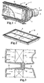
- the clean air-side housing part 3 is provided with a discharge connection 5, via which the cleaned intake air is forwarded in the direction of the arrow 7 in the direction of the cylinder of the internal combustion engine.
- fastening elements 6 are provided on the outside, which can in particular be manually attached or loosened.
- a filter element 8 is shown, which in the filter housing according to Fig. 1 is to use.
- the filter element 8 is formed rectangular, wherein the end faces form the raw or clean side.
- the filter element 8 is enclosed by a frame 9, which may be a carrier of a circumferential sealing element.
- the filter element 8 forms an exchangeable filter insert part 10 together with the frame 9 and possibly the circumferential sealing element.
- the circumferential sealing element which consists for example of PUR foam, molded or molded directly onto the filter element.
- a recess 11 into which a plug-shaped damping element 12 is inserted.
- a plurality of recesses 11 for receiving such damping elements 12 are introduced into the filter element 8, wherein the recesses may be introduced both symmetrically and non-symmetrically in the filter element.
- the recess 11 extends between the raw and the clean side of the filter element.
- the damping element is expediently made of the same material as the sealing element revolving on the filter element, for example of PUR foam, and can be produced in the same operation as the peripheral sealing element.
- each housing part 3 4 respectively housing housings 13 and 14 integrally formed, which are integrally formed with the respective housing part.
- a first housing dome 13 is located on the inside of the raw air-side housing part 4 and projects into the recess 11, which is introduced into the filter element 8.
- the second housing dome 14 is located the inside of the clean air side housing part 3, wherein in the mounting position according to Fig. 3 the two conically shaped housing domes 13 and 14 are aligned coaxially with each other and the respective end faces of the housing domes facing each other.
- the second housing dome 14 on the clean air-side housing part 3 is located directly in the area of the clean air-side outer surface of the filter element 8. Between the end faces of housing dome 13 and housing dome 14, the damping element 12 is inserted into the recess 11.
- the filter element can be clamped by the damping element in interaction with the housing dome on a housing part, so that when opening the filter housing, the filter element with the male half to be removed and especially in hard-to-reach space an element change is facilitated.
- the filter element may consist of folded filter material such as filter paper. But there are also other filter media or filter shapes into consideration, for example, flat filter forms of nonwoven material.
- the housing domes are expediently designed such that the folds of the filter element are stabilized and thus do not collapse, for example in the case of a water entry.
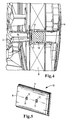
- Fig. 4 a more detailed section through the filter element 8 and the housing parts 3 and 4 is shown.
- the raw air side housing dome 13 on the raw air side housing part 4 projects into the recess 11 in the filter element 8.
- the front side of the dome 13 has a recess into which the plug-shaped damping element 12 is inserted.
- the damping element 12 is located completely within the recess 11 in the filter element 8.
- the second housing dome 14 on the clean air-side housing part 3 touches the damping element 12 with its end face.
- the damping element 12 is pressed from the end face of the housing dome 14 into the seat in the opposite housing dome 13.
- the front side of the housing dome 14 is only on loose contact with the damping element 12, so that when disassembling the housing domes 13 and 14 can be removed from each other.
- a filter element 8 is shown with a total of two mutually spaced recesses 11, in each of which a plug-shaped damping element 12 is inserted.
- the filter box can for example be installed edgewise, i. the separation between the blank air cover and the opposite housing part is vertical.
- the Rohluftdeckel is pivoted away in this case after loosening the top accessible screws on a hinge.
- damping element pivots the filter element with the Rohluftdeckel to the outside and can be removed in a simple manner.
Landscapes
- Chemical & Material Sciences (AREA)
- Chemical Kinetics & Catalysis (AREA)
- Filtering Of Dispersed Particles In Gases (AREA)
Abstract
Description
- Die Erfindung bezieht sich auf eine Filtereinrichtung zur Filtration gasförmiger Fluide, insbesondere auf einen Luftfilter in Kraftfahrzeugen, nach dem Oberbegriff des Anspruches 1.
- In der
DE 196 38 790 A1 wird ein Ansaugluftfilter für eine Brennkraftmaschine beschrieben, bestehend aus einem als Einsatzteil ausgebildeten Filterelement in einem Filtergehäuse. Das Filtergehäuse weist einen Gehäusegrundkörper und einen öffenbaren Deckel auf, der um eine Achse schwenkbar am Gehäusegrundkörper gelagert ist. Bei abgenommenem Deckel kann das Filterelement in das Gehäuseinnere eingesetzt bzw. aus diesem entnommen werden. Das Filterelement ist von einem Rahmen eingefasst, an dem ein Dichtelement angeordnet ist, das im Gehäuseinneren in Dichtanlage mit einer Gehäuseinnenwand steht, um die Roh- von der Reinseite des Filterelements druckdicht zu separieren.
Die SchriftDE 198 59 854 A1 offenbart einen Filter mit Versteifungen an den Gehäuseschalen. Die Versteifungen bestehen aus einer Stütze. Die Gehäuseteile sind mit einer Verbindungsschraube fest verbunden. Die Stützen haben direkten Kontakt miteinander, wobei eine Zusatzdichtung das Filterelement und Roh- und Reinluftseite zur Stütze hin abdichtet. In derUS 4 498 989 A ist ein Luftfilter beschrieben, der aus zwei Gehäuseteilen besteht, zwischen denen ein rundes Filterelement eingelegt ist. Zwischen Gehäuseoberteil und einem ringförmigen Rahmen zur Elementaufnahme ist eine ringförmige Dichtung aufgenommen. - Dieser Luftfilter zeichnet sich durch einfache Austauschbarkeit des Filterelementes aus. Um einer Schallentwicklung entgegenzusteuern, die bei einem Einbau des Luftfilters im Ansaugtrakt der Brennkraftmaschine auf Grund von Motorvibrationen sowie Druckschwankungen aus dem Motor durch Vibrationen des Gehäuses und/oder des Filterelementes entstehen können, können als Verspannungsmaßnahmen zusätzliche Befestigungselemente vorgesehen sein, über die das Filterelement fest mit den Gehäuseteilen zu verbinden ist, beispielsweise über Zuganker, die das Filterelement durchragen. Nachteilig hierbei ist allerdings, dass zum Austausch des Filterelementes die Befestigungseinrichtung gelöst werden muss, was jedoch auf Grund der beengten Platzverhältnisse im Motorraum nur möglich ist, wenn das gesamte Filtergehäuse herausgenommen wird. Dies stellt jedoch einen erheblichen Montageaufwand dar.
- Der Erfindung liegt die Aufgabe zugrunde, mit einfachen konstruktiven Maßnahmen eine Filtereinrichtung zur Filtration gasförmiger Fluide montagefreundlich auszubilden, wobei zugleich das Filterelement im montierten Zustand zur Reduzierung von Schwingungen mit dem Filtergehäuse verspannt sein soll.
- Diese Aufgabe wird erfindungsgemäß mit den Merkmalen des Anspruches 1 gelöst. Die Unteransprüche geben zweckmäßige Weiterbildungen an.
- Die erfindungsgemäße Filtereinrichtung zur Filtration gasförmiger Fluide wird insbesondere als Ansaugluftfilter im Ansaugtrakt von Brennkraftmaschinen zur Filtration der den Zylindern der Brennkraftmaschine zuzuführenden Verbrennungsluft eingesetzt. Grundsätzlich kommt aber auch eine anderweitige Verwendung für die Filtration von Gasen in Betracht, beispielsweise zur Filtration der dem Fahrzeuginnenraum zuzuführenden Luft.
- Die Filtereinrichtung weist ein mehrteiliges Gehäuse sowie ein in das Gehäuse einsetzbares Filterelement auf, wobei im montierten Zustand die Gehäuseteile miteinander verbunden sind. Erfindungsgemäß ist eine das Filterelement durchsetzende Verbindungseinrichtung zur Verbindung der Gehäuseteile vorgesehen, wobei die Verbindungseinrichtung mindestens einen einteilig mit einem Gehäuseteil ausgebildeten Gehäusedom und ein Dämpfungselement umfasst, das zwischen der Stirnseite des Gehäusedoms und dem gegenüberliegenden Gehäuseteil angeordnet ist.
- Diese Ausführung erlaubt ein Verspannen zwischen dem Filterelement und den Gehäuseteilen, von denen mindestens ein Gehäuseteil einen Gehäusedom aufweist, welcher einteilig mit dem Gehäuseteil ausgebildet ist und in das Filterelement einragt, bzw. durch dieses hindurchragt. Zwischen dem Gehäusedom und dem zweiten Gehäuseteil liegt das Dämpfungselement, so dass trotz eines Druckkontaktes zwischen den Gehäuseteilen Schwingungen stark gedämpft werden. Zugleich ist das Filterelement quer zur Längsachse des Gehäusedoms von diesem fixiert, so dass auch in Querrichtung die Ausbildung von Geräusch entwickelnden Schwingungen signifikant reduziert ist.
- Der durch das Filterelement zumindest teilweise hindurchragende Gehäusedom liegt vorteilhafterweise lediglich auf Druckkontakt zum gegenüberliegenden Gehäuseteil, so dass eine einfach lösbare Verbindung zwischen den Gehäuseteilen gegeben ist, die lediglich Druckkräfte über das zwischenliegende Dämpfungselement überträgt, jedoch keine Zugkräfte. Diese Ausführung hat den Vorteil, dass sowohl die Montage als auch die Demontage des Filterelements im Filtergehäuse mit einfachen und schnell durchzuführenden Maßnahmen und ohne Hilfswerkzeug möglich ist. Es genügt, das Filterelement in die vorgesehene Position im Gehäuseinneren einzusetzen und anschließend das Gehäuseteil einzuführen und den daran angeformten Gehäusedom durch die Ausnehmung im Filterelement hindurchzuführen, wobei ggf. zusätzliche Befestigungselemente zur Arretierung der Gehäuseteile aneinander im außen liegenden Bereich des Filtergehäuses vorgesehen sein können, beispielsweise manuell zu öffnende und zu schließende Klammern. Auf diese Weise werden die Gehäuseteile auf gegenseitigen Druck belastet, so dass der durch die Ausnehmung im Filterelement hindurchragende Gehäusedom einen Druck auf das zwischenliegende Dämpfungselement und weiter auf das gegenüberliegende Gehäuseteil ausübt. Durch die hierbei erzielte Verspannung wird die Schwingungsentwicklung signifikant reduziert bzw. unterbunden.
- Umgekehrt ist eine Demontage, also ein Entnehmen des Filterelementes aus dem Filtergehäuse, mit einfachen Maßnahmen möglich, da lediglich die äußeren Befestigungseinrichtungen gelöst werden müssen, damit das den Gehäusedom aufweisende Gehäuseteil aus seiner Montageposition entfernt werden kann. Da der Gehäusedom nur auf Kontakt zum Dämpfungselement liegt und/oder das Dämpfungselement auf Kontakt zum gegenüberliegenden Gehäuseteil, kann das erste, den Gehäusedom aufweisende Gehäuseteil oder das gegenüberliegende Gehäuseteil ohne Hilfsmittel entfernt werden.
- Es kann zweckmäßig sein, auch an dem zweiten Gehäuseteil einen Gehäusedom anzuformen, wobei die Stirnseiten der beiden Gehäusedome einander zugewandt und koaxial zueinander ausgerichtet sind und das Dämpfungselement zwischen den Stirnseiten der Gehäusedome positioniert ist.
- Gegebenenfalls ist es zweckmäßig, das Dämpfungselement mit einem der Gehäuseteile, insbesondere mit einem Gehäusedom zu verbinden, beispielsweise dergestalt, dass in die Stirnseite des Gehäusedoms eine Ausnehmung eingebracht ist, in die das Dämpfungselement einsetzbar ist. Hierdurch wird eine vorgefertigte Verbindung zwischen Gehäusedom und Dämpfungselement erreicht, was die Montage vereinfacht.
- Möglich ist aber auch, das Dämpfungselement unmittelbar in die Ausnehmung in dem Filterelement einzusetzen und anschließend zur Montage den mindestens einen Gehäusedom auf Kontakt zu dem Dämpfungselement zu bringen.
- Im Falle von zwei Gehäusedomen, die in Montageposition Stirnseite an Stirnseite mit zwischenliegendem Dämpfungselement angeordnet sind, ragt zumindest einer der Gehäusedome in die Ausnehmung in dem Filterelement ein, wobei der zweite Gehäusedom entweder ebenfalls teilweise in die Ausnehmung einragt oder sich nur in Nachbarschaft zur Außenseite des Filterelementes befindet.
- Das Dämpfungselement ist vorzugsweise als Dämpfungsstopfen bzw. Dämpfungspfropfen ausgeführt und besteht aus einem schwingungsdämpfenden Material, beispielsweise Polyurethan (PUR). In der Ausführung als PUR-Schaum kann das Dichtmaterial in die Ausnehmung eingegossen werden. Spritzfähiges Dichtmaterial kann auch an das Filterelement angespritzt sein. Die Ausführung als Stopfen bzw. Pfropfen hat den Vorteil, dass das Dämpfungselement beispielsweise unmittelbar in die stirnseitige Ausnehmung an dem Gehäusedom eingesetzt werden kann oder in die Ausnehmung, welche in das Filterelement eingebracht ist, und durch die zumindest ein Gehäusedom wenigstens teilweise hindurchragt.
- Das Filterelement weist mindestens eine Ausnehmung zur Verspannung mithilfe des Gehäusedoms auf. Es kann aber zweckmäßig sein, eine Mehrzahl von beabstandeten Ausnehmungen im Filterelement vorzusehen, in die jeweils ein oder zwei Gehäusedome einragen, um über eine größere Fläche eine Verspannung zwischen Filterelement und Gehäuseteilen zu erreichen und hierdurch die Schwingungsreduzierung zu verbessern.
- Weitere Vorteile und zweckmäßige Ausführungen sind den weiteren Ansprüchen, der Figurenbeschreibung und den Zeichnungen zu entnehmen. Es zeigen:
-
Fig. 1 eine perspektivische Ansicht einer Filtereinrichtung zur Filtration der Ansaugluft in Brennkraftmaschinen, mit einem mehrteiligen Filtergehäuse zur Aufnahme eines Filterelementes, -
Fig. 2 in perspektivischer Einzeldarstellung ein Filterelement mit einem Dämpfungspfropfen, der in eine Ausnehmung eingesetzt ist, die in das Zentrum des Filterelementes eingebracht ist, -
Fig.3 in vergrößerter Darstellung einen Schnitt durch das Filterelement, mit den beiden Gehäuseteilen des Filtergehäuses, an denen jeweils ein Gehäusedom angeformt ist, wobei einer der Gehäusedome durch die Ausnehmung in dem Filterelement hindurchragt und zwischen den Stirnseiten der koaxial angeordneten Gehäusedome ein Dämpfungselement angeordnet ist, -
Fig. 4 einen weiteren Schnitt durch die Filtereinrichtung, -
Fig.5 eine weitere perspektivische Einzeldarstellung eines Filterelementes in alternativer Ausführung. - In den Figuren sind gleiche Bauteile mit gleichen Bezugszeichen versehen.
- Wie
Fig. 1 zu entnehmen, besteht die Filtereinrichtung 1 zur Filtration der Ansaugluft in Brennkraftmaschinen aus einem zweiteiligen Filtergehäuse 2, das sich aus einem reinluftseitigen Gehäuseteil 3 und einem rohluftseitigen Gehäuseteil 4 zusammensetzt. In dem Gehäuseinneren des Filtergehäuses 2 ist ein Element zur Filtration der herangeführten Verbrennungsluft angeordnet. Das reinluftseitige Gehäuseteil 3 ist mit einem Abströmstutzen 5 versehen, über den in Pfeilrichtung 7 die gereinigte Ansaugluft in Richtung der Zylinder der Brennkraftmaschine weitergeleitet wird. Zur lösbaren Befestigung der beiden Gehäuseteile 3 und 4 aneinander sind Befestigungselemente 6 an der Außenseite vorgesehen, die insbesondere manuell befestigt bzw. gelöst werden können. - In
Fig. 2 ist ein Filterelement 8 dargestellt, welches in das Filtergehäuse gemäßFig. 1 einzusetzen ist. Das Filterelement 8 ist rechteckförmig ausgebildet, wobei die Stirnseiten die Roh- bzw. Reinseite bilden. Das Filterelement 8 ist von einem Rahmen 9 eingefasst, welcher Träger eines umlaufenden Dichtungselementes sein kann. Das Filterelement 8 bildet gemeinsam mit dem Rahmen 9 und ggf. dem umlaufenden Dichtungselement ein austauschbares Filtereinsatzteil 10. - Auf den Rahmen 9 kann ggf. auch verzichtet werden; in dieser Ausführung wird das umlaufende Dichtungselement, das beispielsweise aus PUR-Schaum besteht, direkt an das Filterelement angegossen oder angespritzt.
- Im Zentrum des Filterelementes 8 - bezogen auf die orthogonal zur Durchströmungsrichtung liegende Filterebene des Filterelements - befindet sich eine Ausnehmung 11, in die ein pfropfenförmiges Dämpfungselement 12 eingesetzt ist. Gegebenenfalls sind in das Filterelement 8 eine Mehrzahl von Ausnehmungen 11 zur Aufnahme derartiger Dämpfungselemente 12 eingebracht, wobei die Ausnehmungen sowohl symmetrisch als auch nicht-symmetrisch in das Filterelement eingebracht sein können. Die Ausnehmung 11 erstreckt sich zwischen der Roh- und der Reinseite des Filterelements. Das Dämpfungselement besteht zweckmäßigerweise aus dem gleichen Material wie das am Filterelement umlaufende Dichtelement, beispielsweise aus PUR-Schaum, und kann im gleichen Arbeitsgang wie das umlaufende Dichtelement hergestellt werden.
- Wie der Schnittdarstellung gemäß
Fig. 3 zu entnehmen, sind an der Innenseite jedes Gehäuseteils 3, 4 jeweils Gehäusedome 13 bzw. 14 angeformt, die einstückig mit dem jeweiligen Gehäuseteil ausgebildet sind. Ein erster Gehäusedom 13 befindet sich an der Innenseite des rohluftseitigen Gehäuseteils 4 und ragt in die Ausnehmung 11 ein, die in das Filterelement 8 eingebracht ist. Der zweite Gehäusedom 14 befindet sich an der Innenseite des reinluftseitigen Gehäuseteils 3, wobei in der Montageposition gemäßFig. 3 die beiden konisch geformten Gehäusedome 13 und 14 koaxial zueinander ausgerichtet sind und die jeweiligen Stirnseiten der Gehäusedome einander zugewandt sind. Der zweite Gehäusedom 14 am reinluftseitigen Gehäuseteil 3 befindet sich unmittelbar im Bereich der reinluftseitigen Außenfläche des Filterelementes 8. Zwischen den Stirnseiten von Gehäusedom 13 und Gehäusedom 14 ist das Dämpfungselement 12 in die Ausnehmung 11 eingesetzt. - In der montierten Position werden über die Befestigungselemente 6 (
Fig. 1 ) die Gehäuseteile 3 und 4 mit einer Klemmkraft aneinander gehalten, die quer zur Filterelementebene gerichtet ist. Diese Kraft wird auch über die beiden Gehäusedome 13 und 14 und das zwischenliegende Dämpfungselement 12 übertragen, wobei das Dämpfungselement 12 zumindest zu einem der unmittelbar benachbarten Gehäusedome 13, 14 nur auf losen Kontakt liegt, so dass mit dem Öffnen der äußeren Befestigungselemente die Gehäuseteile 3, 4 ohne weiteres voneinander entfernt werden können, so dass das Filterelement 8 zugänglich ist und aus dem Gehäuseinneren entfernt bzw. in das Gehäuseinnere eingesetzt werden kann. - Das Filterelement kann von dem Dämpfungselement im Zusammenspiel mit dem Gehäusedom an einem Gehäuseteil festgeklemmt sein, so dass beim Öffnen des Filtergehäuses das Filterelement mit der abzunehmenden Gehäusehälfte gelöst und insbesondere bei schwer zugänglichem Bauraum ein Elementwechsel erleichtert wird.
- Das Filterelement kann aus gefaltetem Filtermaterial wie zum Beispiel Filterpapier bestehen. Es kommen aber auch andere Filtermedien bzw. Filterformen in Betracht, beispielsweise flächige Filterformen aus Vliesmaterial. Bei gefaltetem Filtermaterial sind die Gehäusedome zweckmäßigerweise so gestaltet, dass die Falten des Filterelements stabilisiert werden und somit zum Beispiel im Falle eines Wassereintrags nicht kollabieren.
- In
Fig. 4 ist ein detaillierterer Schnitt durch das Filterelement 8 und die Gehäuseteile 3 und 4 dargestellt. Der rohluftseitige Gehäusedom 13 an dem rohluftseitigen Gehäuseteil 4 ragt in die Ausnehmung 11 im Filterelement 8 ein. Die Stirnseite des Doms 13 weist eine Ausnehmung auf, in die das stopfenförmige Dämpfungselement 12 eingesetzt ist. Das Dämpfungselement 12 befindet sich komplett innerhalb der Ausnehmung 11 im Filterelement 8. - Der zweite Gehäusedom 14 am reinluftseitigen Gehäuseteil 3 berührt mit seiner Stirnseite das Dämpfungselement 12. Im montierten Zustand wird das Dämpfungselement 12 von der Stirnseite des Gehäusedoms 14 in den Sitz in dem gegenüberliegenden Gehäusedom 13 gedrückt. Die Stirnseite des Gehäusedoms 14 liegt nur auf losem Kontakt mit dem Dämpfungselement 12, so dass bei der Demontage die Gehäusedome 13 und 14 voneinander entfernt werden können.
- In
Fig. 5 ist ein Filterelement 8 mit insgesamt zwei zueinander beabstandeten Ausnehmungen 11 dargestellt, in die jeweils ein stopfenförmiges Dämpfungselement 12 eingesetzt ist. - Der Filterkasten kann beispielsweise hochkant eingebaut werden, d.h. die Trennung zwischen Rohluftdeckel und gegenüberliegenden Gehäuseteil verläuft vertikal. Der Rohluftdeckel wird in diesem Fall nach dem Lösen der an der Oberseite zugänglichen Schrauben an einem Scharnier weggeschwenkt. Durch das am Deckel verklemmte und im Filterelement vergossene Dämpfungselement schwenkt das Filterelement mit dem Rohluftdeckel nach außen und kann in einfacher Weise entnommen werden.
Claims (11)
- Filterelement (8), insbesondere Luftfilterelement, das ein umlaufendes Dichtungselement aufweist, das zur Trennung einer Reinseite von einer Rohseite ausgebildet ist, wobei das Filterelement (8) und ein austauschbares Filtereinsatzteil bildet, dadurch gekennzeichnet, dass das Filterelement (8) zumindest eine Ausnehmung (11) aufweist, die sich zwischen der Reinseite und der Rohseite erstreckt, wobei in der zumindest einen Ausnehmung (11) ein pfropfenförmiges Dämpfungselement (12) aufgenommen ist.
- Filterelement (8) nach Anspruch 1, dadurch gekennzeichnet, dass das pfropfenförmige Dämpfungselement (12) ein schwingungsdämpfendes Material aufweist oder daraus besteht.
- Filterelement (8) nach Anspruch 1 oder 2, dadurch gekennzeichnet, dass- die zumindest eine Ausnehmung (11) zentrisch in dem Filterelement (8) vorliegt oder- das Filterelement (8) zwei oder mehr Ausnehmungen (11) aufweist, die zueinander beabstandet sind und/oder die symmetrisch oder nicht-symmetrisch in dem Filterelement (8) vorliegen.
- Filterelement (8) nach zumindest einem der Ansprüche 1 bis 3, dadurch gekennzeichnet, dass das Dämpfungselement (12) und/oder die Ausnehmung (11) einen kreisförmigen Querschnitt haben.
- Filterelement (8) nach zumindest einem der Ansprüche 1 bis 4, dadurch gekennzeichnet, dass das Dämpfungselement (12) Teil einer Verbindungseinrichtung für zwei Gehäuseteile (3, 4) eines Filtergehäuses ist, wobei die Verbindungseinrichtung mindestens einen einteilig mit einem Gehäuseteil (3, 4) ausgebildeten Gehäusedom (13, 14) und das Dämpfungselement (12) umfasst, das dazu ausgebildet ist, zwischen der Stirnseite des Gehäusedoms (13, 14) und dem gegenüberliegenden Gehäuseteil (3, 4) angeordnet zu werden.
- Filterelement (8) nach Anspruch 5, dadurch gekennzeichnet, dass sich das Dämpfungselement (12) komplett innerhalb der Ausnehmung (11) im Filterelement (8) befindet, wobei bevorzugt das Dämpfungselement (12) einseitig eine Querschnittsverjüngung aufweist, mit der das Dämpfungselement (12) in den Gehäusedom (13, 14) einsetzbar ist, und wobei zwischen dem Dämpfungselement (12) und der Ausnehmung (11) ein Ringspalt vorliegt.
- Filterelement (8) nach zumindest einem der Ansprüche 1 bis 6, dadurch gekennzeichnet, dass das Dämpfungselement (12)- aus dem gleichen Material wie das umlaufende Dichtelement besteht, bevorzugt aus PUR-Schaum und/oder- im Filterelement vergossen ist.
- Filterelement (8) nach zumindest einem der Ansprüche 1 bis 7, dadurch gekennzeichnet, dass das Dichtungselement- direkt an das Filterelement (8) angegossen oder angespritzt ist oder- von einem Rahmen (9) eingefasst ist, der das umlaufende Dichtungselement trägt.
- Filterelement (8) nach zumindest einem der Ansprüche 1 bis 8, dadurch gekennzeichnet, dass das Filterelement (8) rechteckförmig ausgebildet ist, wobei die Stirnseiten die Roh- bzw. Reinseite bilden.
- Filterelement (8) nach zumindest einem der Ansprüche 1 bis 9, dadurch gekennzeichnet, dass das Filterelement (8)- aus gefaltetem Filtermaterial, bevorzugt Filterpapier, besteht oder- ein flächiges Filtermaterial, bevorzugt ein Vliesmaterial, aufweist.
- Filtereinrichtung zur Filtration gasförmiger Fluide, insbesondere Luftfilter in Kraftfahrzeugen, mit einem in ein mehrteiliges Gehäuse (2) einsetzbaren Filterelement, wobei mindestens zwei Gehäuseteile (3, 4) im montierten Zustand miteinander verbunden sind, dadurch gekennzeichnet, dass- eine das Filterelement (8) durchsetzende Verbindungseinrichtung für eine Verbindung zwischen den Gehäuseteilen (3, 4) vorgesehen ist und- das Filterelement ein Filterelement (8) nach zumindest einem der Ansprüche 1 bis 10 ist, und- die Verbindungseinrichtung mindestens einen einteilig mit einem Gehäuseteil (3, 4) ausgebildeten Gehäusedom (13, 14) umfasst, wobei zwischen der Stirnseite dem Gehäusedom (13, 14) und dem gegenüberliegenden Gehäuseteil (3, 4) das Dämpfungselement (12) des Filterelements (8) angeordnet ist.
Priority Applications (1)
| Application Number | Priority Date | Filing Date | Title |
|---|---|---|---|
| EP21197238.5A EP3943176A1 (de) | 2009-02-16 | 2010-02-16 | Filterelement und filtereinrichtung zur filtration gasförmiger fluide |
Applications Claiming Priority (2)
| Application Number | Priority Date | Filing Date | Title |
|---|---|---|---|
| DE202009002178U DE202009002178U1 (de) | 2009-02-16 | 2009-02-16 | Filtereinrichtung zur Filtration gasförmiger Fluide |
| EP10153673.8A EP2223727B2 (de) | 2009-02-16 | 2010-02-16 | Filtereinrichtung zur Filtration gasförmiger Fluide |
Related Parent Applications (2)
| Application Number | Title | Priority Date | Filing Date |
|---|---|---|---|
| EP10153673.8A Division EP2223727B2 (de) | 2009-02-16 | 2010-02-16 | Filtereinrichtung zur Filtration gasförmiger Fluide |
| EP10153673.8A Division-Into EP2223727B2 (de) | 2009-02-16 | 2010-02-16 | Filtereinrichtung zur Filtration gasförmiger Fluide |
Related Child Applications (1)
| Application Number | Title | Priority Date | Filing Date |
|---|---|---|---|
| EP21197238.5A Division EP3943176A1 (de) | 2009-02-16 | 2010-02-16 | Filterelement und filtereinrichtung zur filtration gasförmiger fluide |
Publications (2)
| Publication Number | Publication Date |
|---|---|
| EP3103543A1 true EP3103543A1 (de) | 2016-12-14 |
| EP3103543B1 EP3103543B1 (de) | 2021-09-22 |
Family
ID=42026429
Family Applications (3)
| Application Number | Title | Priority Date | Filing Date |
|---|---|---|---|
| EP10153673.8A Active EP2223727B2 (de) | 2009-02-16 | 2010-02-16 | Filtereinrichtung zur Filtration gasförmiger Fluide |
| EP21197238.5A Withdrawn EP3943176A1 (de) | 2009-02-16 | 2010-02-16 | Filterelement und filtereinrichtung zur filtration gasförmiger fluide |
| EP16179925.9A Active EP3103543B1 (de) | 2009-02-16 | 2010-02-16 | Filterelement und filtereinrichtung zur filtration gasförmiger fluide |
Family Applications Before (2)
| Application Number | Title | Priority Date | Filing Date |
|---|---|---|---|
| EP10153673.8A Active EP2223727B2 (de) | 2009-02-16 | 2010-02-16 | Filtereinrichtung zur Filtration gasförmiger Fluide |
| EP21197238.5A Withdrawn EP3943176A1 (de) | 2009-02-16 | 2010-02-16 | Filterelement und filtereinrichtung zur filtration gasförmiger fluide |
Country Status (4)
| Country | Link |
|---|---|
| US (2) | US8298310B2 (de) |
| EP (3) | EP2223727B2 (de) |
| DE (1) | DE202009002178U1 (de) |
| ES (1) | ES2893290T3 (de) |
Cited By (2)
| Publication number | Priority date | Publication date | Assignee | Title |
|---|---|---|---|---|
| DE102022106562A1 (de) | 2022-03-21 | 2023-09-21 | Mann+Hummel Gmbh | Filterelement und Filtersystem |
| WO2025099262A1 (de) | 2023-11-10 | 2025-05-15 | Mann+Hummel Gmbh | Luftfilter mit zentral an einem flachfilterelement angreifenden stützstrukturen |
Families Citing this family (10)
| Publication number | Priority date | Publication date | Assignee | Title |
|---|---|---|---|---|
| DE102012016558A1 (de) * | 2012-08-22 | 2014-02-27 | Mann+Hummel Gmbh | Filtereinrichtung, insbesondere zur Gasfiltration |
| DE102013000111A1 (de) * | 2013-01-05 | 2014-07-10 | Volkswagen Aktiengesellschaft | Filtervorrichtung und ein Filtereinsatz für eine solche Vorrichtung |
| DE102013011612A1 (de) | 2013-03-25 | 2014-09-25 | Mann + Hummel Gmbh | Filterelement mit Abstützelementen, Filter mit einem Filterelement und Filtergehäuse eines Filters |
| US9970351B2 (en) * | 2013-11-19 | 2018-05-15 | Cummins Filtration Ip, Inc. | High frequency silencer for an air induction system |
| US9404451B2 (en) * | 2014-04-11 | 2016-08-02 | GM Global Technology Operations LLC | Automotive air cleaner elements with attachment/insulation feature |
| DE102014013278A1 (de) | 2014-09-12 | 2016-03-17 | Mann + Hummel Gmbh | Plattenförmiges Filterelement zur Gasfiltration |
| DE102015011660A1 (de) | 2014-09-12 | 2016-03-17 | Mann + Hummel Gmbh | Filtereinrichtung zur Gasfiltration |
| DE102015006496A1 (de) | 2015-05-22 | 2016-11-24 | Mann + Hummel Gmbh | Filterelement, insbesondere zur Gasfiltration |
| DE102017003997A1 (de) | 2016-04-27 | 2017-11-02 | Mann+Hummel Gmbh | Flachluftfilterelement und Luftfilter |
| EP4570352A1 (de) | 2023-12-13 | 2025-06-18 | MANN+HUMMEL GmbH | Umgebungsluftfiltervorrichtung und filterelement in der umgebungsluftfiltervorrichtung |
Citations (7)
| Publication number | Priority date | Publication date | Assignee | Title |
|---|---|---|---|---|
| US4498989A (en) | 1981-02-23 | 1985-02-12 | Nippondenso Co., Ltd. | Fluid filter element and support |
| GB2162087A (en) * | 1984-05-21 | 1986-01-29 | Honda Motor Co Ltd | Air filter |
| DE19638790A1 (de) | 1996-09-21 | 1998-03-26 | Mann & Hummel Filter | Luftfilter |
| DE19859854A1 (de) | 1998-12-23 | 2000-06-29 | Mann & Hummel Filter | Filter mit einem durch mindestens eine Verstärkung verstärkten Gehäuse |
| EP2119497A1 (de) * | 2006-12-27 | 2009-11-18 | Biochromat Co., Ltd. | Stopfen zum entfernen einer flüchtigen substanz, gefäss zum entfernen einer flüchtigen substanz und vorrichtung zum entfernen einer flüchtigen substanz |
| EP3002021A1 (de) * | 2014-10-02 | 2016-04-06 | Gerresheimer Regensburg GmbH | Stopfen zum aufsetzen auf ein anschlusselement einer medizinischen spritze |
| EP3514297A1 (de) * | 2018-01-20 | 2019-07-24 | Friedrich Wilhelm Neikes | Profilschiene mit stopfen zur befestigung auf einer verschalung |
Family Cites Families (7)
| Publication number | Priority date | Publication date | Assignee | Title |
|---|---|---|---|---|
| CA978100A (en) | 1970-12-31 | 1975-11-18 | Ford Motor Company Of Canada | Air cleaner having reduced height |
| US3859068A (en) * | 1972-05-09 | 1975-01-07 | Tenneco Inc | Pleated air filter |
| US3881250A (en) * | 1972-11-08 | 1975-05-06 | Mcculloch Corp | Chain saw filter assembly |
| FR2261041B1 (de) * | 1974-02-18 | 1978-03-31 | Cfea | |
| US3950157A (en) * | 1974-10-07 | 1976-04-13 | Dorrance Henry Matney | Ram air filter for light aircraft |
| AU540096B2 (en) † | 1982-08-04 | 1984-11-01 | Nippondenso Co. Ltd. | Filter device and manufacturing method |
| DE4218396B4 (de) * | 1992-06-04 | 2004-04-01 | Mann + Hummel Gmbh | Filtereinrichtung, insbesondere zum Filtrieren der Ansaugluft eines Verbrennungsmotors |
-
2009
- 2009-02-16 DE DE202009002178U patent/DE202009002178U1/de not_active Expired - Lifetime
-
2010
- 2010-02-16 US US12/706,010 patent/US8298310B2/en not_active Ceased
- 2010-02-16 ES ES16179925T patent/ES2893290T3/es active Active
- 2010-02-16 EP EP10153673.8A patent/EP2223727B2/de active Active
- 2010-02-16 EP EP21197238.5A patent/EP3943176A1/de not_active Withdrawn
- 2010-02-16 EP EP16179925.9A patent/EP3103543B1/de active Active
-
2014
- 2014-10-30 US US14/528,542 patent/USRE46182E1/en active Active
Patent Citations (7)
| Publication number | Priority date | Publication date | Assignee | Title |
|---|---|---|---|---|
| US4498989A (en) | 1981-02-23 | 1985-02-12 | Nippondenso Co., Ltd. | Fluid filter element and support |
| GB2162087A (en) * | 1984-05-21 | 1986-01-29 | Honda Motor Co Ltd | Air filter |
| DE19638790A1 (de) | 1996-09-21 | 1998-03-26 | Mann & Hummel Filter | Luftfilter |
| DE19859854A1 (de) | 1998-12-23 | 2000-06-29 | Mann & Hummel Filter | Filter mit einem durch mindestens eine Verstärkung verstärkten Gehäuse |
| EP2119497A1 (de) * | 2006-12-27 | 2009-11-18 | Biochromat Co., Ltd. | Stopfen zum entfernen einer flüchtigen substanz, gefäss zum entfernen einer flüchtigen substanz und vorrichtung zum entfernen einer flüchtigen substanz |
| EP3002021A1 (de) * | 2014-10-02 | 2016-04-06 | Gerresheimer Regensburg GmbH | Stopfen zum aufsetzen auf ein anschlusselement einer medizinischen spritze |
| EP3514297A1 (de) * | 2018-01-20 | 2019-07-24 | Friedrich Wilhelm Neikes | Profilschiene mit stopfen zur befestigung auf einer verschalung |
Cited By (2)
| Publication number | Priority date | Publication date | Assignee | Title |
|---|---|---|---|---|
| DE102022106562A1 (de) | 2022-03-21 | 2023-09-21 | Mann+Hummel Gmbh | Filterelement und Filtersystem |
| WO2025099262A1 (de) | 2023-11-10 | 2025-05-15 | Mann+Hummel Gmbh | Luftfilter mit zentral an einem flachfilterelement angreifenden stützstrukturen |
Also Published As
| Publication number | Publication date |
|---|---|
| ES2893290T3 (es) | 2022-02-08 |
| EP2223727B2 (de) | 2019-04-24 |
| US8298310B2 (en) | 2012-10-30 |
| EP2223727B1 (de) | 2016-07-20 |
| DE202009002178U1 (de) | 2010-07-15 |
| US20100206172A1 (en) | 2010-08-19 |
| EP2223727A1 (de) | 2010-09-01 |
| EP3103543B1 (de) | 2021-09-22 |
| EP3943176A1 (de) | 2022-01-26 |
| USRE46182E1 (en) | 2016-10-25 |
Similar Documents
| Publication | Publication Date | Title |
|---|---|---|
| EP2223727B2 (de) | Filtereinrichtung zur Filtration gasförmiger Fluide | |
| DE112009001265B4 (de) | Filtergehäuse einer Filtereinrichtung zur Filtration gasförmiger Fluide | |
| DE19539463B4 (de) | Gehäuse, insbesondere für ein Luftfilter für die Ansaugluft einer Brennkraftmaschine | |
| EP3411129B1 (de) | Filterelement, elementrahmen eines filterelements, filterbalg eines filterelements, filtergehäuse und filter | |
| EP3525913B1 (de) | Rundfilterelement, insbesondere zur gasfiltration | |
| EP2723470B1 (de) | Plattenfilterelement | |
| DE102014006852B4 (de) | Hohlfilterelement, Filtergehäuse und Filter | |
| EP3525910B1 (de) | Filtereinrichtung und rundfilterelement, insbesondere zur gasfiltration | |
| EP1172240A2 (de) | Einschubfilter | |
| WO2015193341A2 (de) | Filter und filtereinsatz | |
| DE102012207960B3 (de) | Partikelfilter | |
| DE202008005603U1 (de) | Verbindungsanordnung für luftführende Bauelemente in einem Fahrzeug | |
| DE102010041948A1 (de) | Filtereinrichtung | |
| WO2017133798A1 (de) | Filtergehäuse und filter | |
| WO2017144289A1 (de) | Filterelement, insbesondere zur gasfiltration | |
| EP1144083A1 (de) | Filter mit einem durch mindestens eine verstärkung verstärkten gehäuse | |
| DE102019210078A1 (de) | Luftfiltermodul | |
| DE102008063720A1 (de) | Filtereinrichtung | |
| DE202005003046U1 (de) | Filtereinsatz für einen ring- oder bogenförmigen Gasfilter | |
| WO2017133797A1 (de) | Filterelement, elementrahmen eines filterelements, filterbalg eines filterelements und filter | |
| EP3419737A1 (de) | Filterelement, insbesondere zur gasfiltration | |
| DE102012012940A1 (de) | Filterhalterahmen für ein Filtersystem | |
| DE102006039952A1 (de) | Luftfilter | |
| DE102007020456B4 (de) | Filterelement für einen Luftfilter einer Brennkraftmaschine | |
| DE10327441A1 (de) | Ansaugluftfilter |
Legal Events
| Date | Code | Title | Description |
|---|---|---|---|
| PUAI | Public reference made under article 153(3) epc to a published international application that has entered the european phase |
Free format text: ORIGINAL CODE: 0009012 |
|
| STAA | Information on the status of an ep patent application or granted ep patent |
Free format text: STATUS: THE APPLICATION HAS BEEN PUBLISHED |
|
| AC | Divisional application: reference to earlier application |
Ref document number: 2223727 Country of ref document: EP Kind code of ref document: P |
|
| AK | Designated contracting states |
Kind code of ref document: A1 Designated state(s): AT BE BG CH CY CZ DE DK EE ES FI FR GB GR HR HU IE IS IT LI LT LU LV MC MK MT NL NO PL PT RO SE SI SK SM TR |
|
| STAA | Information on the status of an ep patent application or granted ep patent |
Free format text: STATUS: REQUEST FOR EXAMINATION WAS MADE |
|
| 17P | Request for examination filed |
Effective date: 20170303 |
|
| RBV | Designated contracting states (corrected) |
Designated state(s): AT BE BG CH CY CZ DE DK EE ES FI FR GB GR HR HU IE IS IT LI LT LU LV MC MK MT NL NO PL PT RO SE SI SK SM TR |
|
| STAA | Information on the status of an ep patent application or granted ep patent |
Free format text: STATUS: EXAMINATION IS IN PROGRESS |
|
| 17Q | First examination report despatched |
Effective date: 20190607 |
|
| GRAP | Despatch of communication of intention to grant a patent |
Free format text: ORIGINAL CODE: EPIDOSNIGR1 |
|
| STAA | Information on the status of an ep patent application or granted ep patent |
Free format text: STATUS: GRANT OF PATENT IS INTENDED |
|
| INTG | Intention to grant announced |
Effective date: 20201211 |
|
| GRAJ | Information related to disapproval of communication of intention to grant by the applicant or resumption of examination proceedings by the epo deleted |
Free format text: ORIGINAL CODE: EPIDOSDIGR1 |
|
| STAA | Information on the status of an ep patent application or granted ep patent |
Free format text: STATUS: EXAMINATION IS IN PROGRESS |
|
| GRAS | Grant fee paid |
Free format text: ORIGINAL CODE: EPIDOSNIGR3 |
|
| STAA | Information on the status of an ep patent application or granted ep patent |
Free format text: STATUS: GRANT OF PATENT IS INTENDED |
|
| GRAP | Despatch of communication of intention to grant a patent |
Free format text: ORIGINAL CODE: EPIDOSNIGR1 |
|
| INTC | Intention to grant announced (deleted) | ||
| RAP3 | Party data changed (applicant data changed or rights of an application transferred) |
Owner name: MANN+HUMMEL GMBH |
|
| INTG | Intention to grant announced |
Effective date: 20210514 |
|
| GRAA | (expected) grant |
Free format text: ORIGINAL CODE: 0009210 |
|
| STAA | Information on the status of an ep patent application or granted ep patent |
Free format text: STATUS: THE PATENT HAS BEEN GRANTED |
|
| AC | Divisional application: reference to earlier application |
Ref document number: 2223727 Country of ref document: EP Kind code of ref document: P |
|
| AK | Designated contracting states |
Kind code of ref document: B1 Designated state(s): AT BE BG CH CY CZ DE DK EE ES FI FR GB GR HR HU IE IS IT LI LT LU LV MC MK MT NL NO PL PT RO SE SI SK SM TR |
|
| REG | Reference to a national code |
Ref country code: GB Ref legal event code: FG4D Free format text: NOT ENGLISH |
|
| REG | Reference to a national code |
Ref country code: IE Ref legal event code: FG4D Free format text: LANGUAGE OF EP DOCUMENT: GERMAN |
|
| REG | Reference to a national code |
Ref country code: DE Ref legal event code: R096 Ref document number: 502010016965 Country of ref document: DE |
|
| REG | Reference to a national code |
Ref country code: CH Ref legal event code: EP Ref country code: AT Ref legal event code: REF Ref document number: 1431866 Country of ref document: AT Kind code of ref document: T Effective date: 20211015 |
|
| REG | Reference to a national code |
Ref country code: LT Ref legal event code: MG9D |
|
| REG | Reference to a national code |
Ref country code: NL Ref legal event code: MP Effective date: 20210922 |
|
| PG25 | Lapsed in a contracting state [announced via postgrant information from national office to epo] |
Ref country code: FI Free format text: LAPSE BECAUSE OF FAILURE TO SUBMIT A TRANSLATION OF THE DESCRIPTION OR TO PAY THE FEE WITHIN THE PRESCRIBED TIME-LIMIT Effective date: 20210922 Ref country code: NO Free format text: LAPSE BECAUSE OF FAILURE TO SUBMIT A TRANSLATION OF THE DESCRIPTION OR TO PAY THE FEE WITHIN THE PRESCRIBED TIME-LIMIT Effective date: 20211222 Ref country code: LT Free format text: LAPSE BECAUSE OF FAILURE TO SUBMIT A TRANSLATION OF THE DESCRIPTION OR TO PAY THE FEE WITHIN THE PRESCRIBED TIME-LIMIT Effective date: 20210922 Ref country code: BG Free format text: LAPSE BECAUSE OF FAILURE TO SUBMIT A TRANSLATION OF THE DESCRIPTION OR TO PAY THE FEE WITHIN THE PRESCRIBED TIME-LIMIT Effective date: 20211222 Ref country code: SE Free format text: LAPSE BECAUSE OF FAILURE TO SUBMIT A TRANSLATION OF THE DESCRIPTION OR TO PAY THE FEE WITHIN THE PRESCRIBED TIME-LIMIT Effective date: 20210922 Ref country code: HR Free format text: LAPSE BECAUSE OF FAILURE TO SUBMIT A TRANSLATION OF THE DESCRIPTION OR TO PAY THE FEE WITHIN THE PRESCRIBED TIME-LIMIT Effective date: 20210922 |
|
| REG | Reference to a national code |
Ref country code: ES Ref legal event code: FG2A Ref document number: 2893290 Country of ref document: ES Kind code of ref document: T3 Effective date: 20220208 |
|
| PG25 | Lapsed in a contracting state [announced via postgrant information from national office to epo] |
Ref country code: LV Free format text: LAPSE BECAUSE OF FAILURE TO SUBMIT A TRANSLATION OF THE DESCRIPTION OR TO PAY THE FEE WITHIN THE PRESCRIBED TIME-LIMIT Effective date: 20210922 Ref country code: GR Free format text: LAPSE BECAUSE OF FAILURE TO SUBMIT A TRANSLATION OF THE DESCRIPTION OR TO PAY THE FEE WITHIN THE PRESCRIBED TIME-LIMIT Effective date: 20211223 |
|
| PG25 | Lapsed in a contracting state [announced via postgrant information from national office to epo] |
Ref country code: IS Free format text: LAPSE BECAUSE OF FAILURE TO SUBMIT A TRANSLATION OF THE DESCRIPTION OR TO PAY THE FEE WITHIN THE PRESCRIBED TIME-LIMIT Effective date: 20220122 Ref country code: SK Free format text: LAPSE BECAUSE OF FAILURE TO SUBMIT A TRANSLATION OF THE DESCRIPTION OR TO PAY THE FEE WITHIN THE PRESCRIBED TIME-LIMIT Effective date: 20210922 Ref country code: RO Free format text: LAPSE BECAUSE OF FAILURE TO SUBMIT A TRANSLATION OF THE DESCRIPTION OR TO PAY THE FEE WITHIN THE PRESCRIBED TIME-LIMIT Effective date: 20210922 Ref country code: PT Free format text: LAPSE BECAUSE OF FAILURE TO SUBMIT A TRANSLATION OF THE DESCRIPTION OR TO PAY THE FEE WITHIN THE PRESCRIBED TIME-LIMIT Effective date: 20220124 Ref country code: PL Free format text: LAPSE BECAUSE OF FAILURE TO SUBMIT A TRANSLATION OF THE DESCRIPTION OR TO PAY THE FEE WITHIN THE PRESCRIBED TIME-LIMIT Effective date: 20210922 Ref country code: NL Free format text: LAPSE BECAUSE OF FAILURE TO SUBMIT A TRANSLATION OF THE DESCRIPTION OR TO PAY THE FEE WITHIN THE PRESCRIBED TIME-LIMIT Effective date: 20210922 Ref country code: EE Free format text: LAPSE BECAUSE OF FAILURE TO SUBMIT A TRANSLATION OF THE DESCRIPTION OR TO PAY THE FEE WITHIN THE PRESCRIBED TIME-LIMIT Effective date: 20210922 Ref country code: CZ Free format text: LAPSE BECAUSE OF FAILURE TO SUBMIT A TRANSLATION OF THE DESCRIPTION OR TO PAY THE FEE WITHIN THE PRESCRIBED TIME-LIMIT Effective date: 20210922 |
|
| REG | Reference to a national code |
Ref country code: DE Ref legal event code: R097 Ref document number: 502010016965 Country of ref document: DE |
|
| PG25 | Lapsed in a contracting state [announced via postgrant information from national office to epo] |
Ref country code: DK Free format text: LAPSE BECAUSE OF FAILURE TO SUBMIT A TRANSLATION OF THE DESCRIPTION OR TO PAY THE FEE WITHIN THE PRESCRIBED TIME-LIMIT Effective date: 20210922 |
|
| PLBE | No opposition filed within time limit |
Free format text: ORIGINAL CODE: 0009261 |
|
| STAA | Information on the status of an ep patent application or granted ep patent |
Free format text: STATUS: NO OPPOSITION FILED WITHIN TIME LIMIT |
|
| 26N | No opposition filed |
Effective date: 20220623 |
|
| PG25 | Lapsed in a contracting state [announced via postgrant information from national office to epo] |
Ref country code: MC Free format text: LAPSE BECAUSE OF FAILURE TO SUBMIT A TRANSLATION OF THE DESCRIPTION OR TO PAY THE FEE WITHIN THE PRESCRIBED TIME-LIMIT Effective date: 20210922 |
|
| REG | Reference to a national code |
Ref country code: CH Ref legal event code: PL |
|
| REG | Reference to a national code |
Ref country code: BE Ref legal event code: MM Effective date: 20220228 |
|
| PG25 | Lapsed in a contracting state [announced via postgrant information from national office to epo] |
Ref country code: LU Free format text: LAPSE BECAUSE OF NON-PAYMENT OF DUE FEES Effective date: 20220216 |
|
| PG25 | Lapsed in a contracting state [announced via postgrant information from national office to epo] |
Ref country code: SI Free format text: LAPSE BECAUSE OF FAILURE TO SUBMIT A TRANSLATION OF THE DESCRIPTION OR TO PAY THE FEE WITHIN THE PRESCRIBED TIME-LIMIT Effective date: 20210922 |
|
| PG25 | Lapsed in a contracting state [announced via postgrant information from national office to epo] |
Ref country code: LI Free format text: LAPSE BECAUSE OF NON-PAYMENT OF DUE FEES Effective date: 20220228 Ref country code: IE Free format text: LAPSE BECAUSE OF NON-PAYMENT OF DUE FEES Effective date: 20220216 Ref country code: CH Free format text: LAPSE BECAUSE OF NON-PAYMENT OF DUE FEES Effective date: 20220228 |
|
| PG25 | Lapsed in a contracting state [announced via postgrant information from national office to epo] |
Ref country code: BE Free format text: LAPSE BECAUSE OF NON-PAYMENT OF DUE FEES Effective date: 20220228 |
|
| REG | Reference to a national code |
Ref country code: AT Ref legal event code: MM01 Ref document number: 1431866 Country of ref document: AT Kind code of ref document: T Effective date: 20220216 |
|
| PG25 | Lapsed in a contracting state [announced via postgrant information from national office to epo] |
Ref country code: AT Free format text: LAPSE BECAUSE OF NON-PAYMENT OF DUE FEES Effective date: 20220216 |
|
| P01 | Opt-out of the competence of the unified patent court (upc) registered |
Effective date: 20230530 |
|
| PG25 | Lapsed in a contracting state [announced via postgrant information from national office to epo] |
Ref country code: HU Free format text: LAPSE BECAUSE OF FAILURE TO SUBMIT A TRANSLATION OF THE DESCRIPTION OR TO PAY THE FEE WITHIN THE PRESCRIBED TIME-LIMIT; INVALID AB INITIO Effective date: 20100216 |
|
| PG25 | Lapsed in a contracting state [announced via postgrant information from national office to epo] |
Ref country code: SM Free format text: LAPSE BECAUSE OF FAILURE TO SUBMIT A TRANSLATION OF THE DESCRIPTION OR TO PAY THE FEE WITHIN THE PRESCRIBED TIME-LIMIT Effective date: 20210922 Ref country code: MK Free format text: LAPSE BECAUSE OF FAILURE TO SUBMIT A TRANSLATION OF THE DESCRIPTION OR TO PAY THE FEE WITHIN THE PRESCRIBED TIME-LIMIT Effective date: 20210922 Ref country code: CY Free format text: LAPSE BECAUSE OF FAILURE TO SUBMIT A TRANSLATION OF THE DESCRIPTION OR TO PAY THE FEE WITHIN THE PRESCRIBED TIME-LIMIT Effective date: 20210922 |
|
| PG25 | Lapsed in a contracting state [announced via postgrant information from national office to epo] |
Ref country code: MT Free format text: LAPSE BECAUSE OF FAILURE TO SUBMIT A TRANSLATION OF THE DESCRIPTION OR TO PAY THE FEE WITHIN THE PRESCRIBED TIME-LIMIT Effective date: 20210922 |
|
| PG25 | Lapsed in a contracting state [announced via postgrant information from national office to epo] |
Ref country code: TR Free format text: LAPSE BECAUSE OF FAILURE TO SUBMIT A TRANSLATION OF THE DESCRIPTION OR TO PAY THE FEE WITHIN THE PRESCRIBED TIME-LIMIT Effective date: 20210922 |
|
| PGFP | Annual fee paid to national office [announced via postgrant information from national office to epo] |
Ref country code: GB Payment date: 20260219 Year of fee payment: 17 |
|
| PGFP | Annual fee paid to national office [announced via postgrant information from national office to epo] |
Ref country code: DE Payment date: 20260218 Year of fee payment: 17 |
|
| PGFP | Annual fee paid to national office [announced via postgrant information from national office to epo] |
Ref country code: IT Payment date: 20260224 Year of fee payment: 17 |
|
| PGFP | Annual fee paid to national office [announced via postgrant information from national office to epo] |
Ref country code: FR Payment date: 20260218 Year of fee payment: 17 |
|
| PGFP | Annual fee paid to national office [announced via postgrant information from national office to epo] |
Ref country code: ES Payment date: 20260408 Year of fee payment: 17 |