EP3103382B1 - Mundspiegelvorrichtung - Google Patents
Mundspiegelvorrichtung Download PDFInfo
- Publication number
- EP3103382B1 EP3103382B1 EP15197220.5A EP15197220A EP3103382B1 EP 3103382 B1 EP3103382 B1 EP 3103382B1 EP 15197220 A EP15197220 A EP 15197220A EP 3103382 B1 EP3103382 B1 EP 3103382B1
- Authority
- EP
- European Patent Office
- Prior art keywords
- wall
- port
- fluid
- mirror apparatus
- mouth mirror
- Prior art date
- Legal status (The legal status is an assumption and is not a legal conclusion. Google has not performed a legal analysis and makes no representation as to the accuracy of the status listed.)
- Active
Links
Images


Classifications
-
- A—HUMAN NECESSITIES
- A61—MEDICAL OR VETERINARY SCIENCE; HYGIENE
- A61B—DIAGNOSIS; SURGERY; IDENTIFICATION
- A61B1/00—Instruments for performing medical examinations of the interior of cavities or tubes of the body by visual or photographical inspection, e.g. endoscopes; Illuminating arrangements therefor
- A61B1/24—Instruments for performing medical examinations of the interior of cavities or tubes of the body by visual or photographical inspection, e.g. endoscopes; Illuminating arrangements therefor for the mouth, i.e. stomatoscopes, e.g. with tongue depressors; Instruments for opening or keeping open the mouth
- A61B1/247—Instruments for performing medical examinations of the interior of cavities or tubes of the body by visual or photographical inspection, e.g. endoscopes; Illuminating arrangements therefor for the mouth, i.e. stomatoscopes, e.g. with tongue depressors; Instruments for opening or keeping open the mouth with means for viewing areas outside the direct line of sight, e.g. dentists' mirrors
- A61B1/253—Instruments for performing medical examinations of the interior of cavities or tubes of the body by visual or photographical inspection, e.g. endoscopes; Illuminating arrangements therefor for the mouth, i.e. stomatoscopes, e.g. with tongue depressors; Instruments for opening or keeping open the mouth with means for viewing areas outside the direct line of sight, e.g. dentists' mirrors with means for preventing fogging
-
- A—HUMAN NECESSITIES
- A61—MEDICAL OR VETERINARY SCIENCE; HYGIENE
- A61B—DIAGNOSIS; SURGERY; IDENTIFICATION
- A61B1/00—Instruments for performing medical examinations of the interior of cavities or tubes of the body by visual or photographical inspection, e.g. endoscopes; Illuminating arrangements therefor
- A61B1/24—Instruments for performing medical examinations of the interior of cavities or tubes of the body by visual or photographical inspection, e.g. endoscopes; Illuminating arrangements therefor for the mouth, i.e. stomatoscopes, e.g. with tongue depressors; Instruments for opening or keeping open the mouth
- A61B1/247—Instruments for performing medical examinations of the interior of cavities or tubes of the body by visual or photographical inspection, e.g. endoscopes; Illuminating arrangements therefor for the mouth, i.e. stomatoscopes, e.g. with tongue depressors; Instruments for opening or keeping open the mouth with means for viewing areas outside the direct line of sight, e.g. dentists' mirrors
-
- A—HUMAN NECESSITIES
- A61—MEDICAL OR VETERINARY SCIENCE; HYGIENE
- A61C—DENTISTRY; APPARATUS OR METHODS FOR ORAL OR DENTAL HYGIENE
- A61C1/00—Dental machines for boring or cutting ; General features of dental machines or apparatus, e.g. hand-piece design
- A61C1/0061—Air and water supply systems; Valves specially adapted therefor
- A61C1/0069—Fluid temperature control
-
- A—HUMAN NECESSITIES
- A61—MEDICAL OR VETERINARY SCIENCE; HYGIENE
- A61C—DENTISTRY; APPARATUS OR METHODS FOR ORAL OR DENTAL HYGIENE
- A61C1/00—Dental machines for boring or cutting ; General features of dental machines or apparatus, e.g. hand-piece design
- A61C1/0061—Air and water supply systems; Valves specially adapted therefor
- A61C1/0084—Supply units, e.g. reservoir arrangements, specially adapted pumps
- A61C1/0092—Pumps specially adapted therefor
-
- A—HUMAN NECESSITIES
- A61—MEDICAL OR VETERINARY SCIENCE; HYGIENE
- A61C—DENTISTRY; APPARATUS OR METHODS FOR ORAL OR DENTAL HYGIENE
- A61C17/00—Devices for cleaning, polishing, rinsing or drying teeth, teeth cavities or prostheses; Saliva removers; Dental appliances for receiving spittle
- A61C17/02—Rinsing or air-blowing devices, e.g. using fluid jets or comprising liquid medication
- A61C17/0202—Hand-pieces
-
- A—HUMAN NECESSITIES
- A61—MEDICAL OR VETERINARY SCIENCE; HYGIENE
- A61C—DENTISTRY; APPARATUS OR METHODS FOR ORAL OR DENTAL HYGIENE
- A61C17/00—Devices for cleaning, polishing, rinsing or drying teeth, teeth cavities or prostheses; Saliva removers; Dental appliances for receiving spittle
- A61C17/02—Rinsing or air-blowing devices, e.g. using fluid jets or comprising liquid medication
- A61C17/0208—Rinsing or air-blowing devices, e.g. using fluid jets or comprising liquid medication combined with means providing suction
-
- A—HUMAN NECESSITIES
- A61—MEDICAL OR VETERINARY SCIENCE; HYGIENE
- A61C—DENTISTRY; APPARATUS OR METHODS FOR ORAL OR DENTAL HYGIENE
- A61C17/00—Devices for cleaning, polishing, rinsing or drying teeth, teeth cavities or prostheses; Saliva removers; Dental appliances for receiving spittle
- A61C17/06—Saliva removers; Accessories therefor
- A61C17/08—Aspiration nozzles
-
- A—HUMAN NECESSITIES
- A61—MEDICAL OR VETERINARY SCIENCE; HYGIENE
- A61C—DENTISTRY; APPARATUS OR METHODS FOR ORAL OR DENTAL HYGIENE
- A61C3/00—Dental tools or instruments
Definitions
- the disclosure relates to a mouth mirror apparatus, more particularly to a mouth mirror apparatus adapted to be connected to a suction device.
- US patent no. 5449290 discloses a dental mirror which has an airflow bore therein to direct an airflow onto a surface of a mirror to dissipate mist or debris generated inside the patient's mouth during a procedure.
- the dental mirror consists of threadably engaged mirror and handle sections, to allow for cleaning and sterilization of the instrument.
- Prior art documents EP2181643 , US6575744 , CN1883373 , CH364866 and US4408991 all disclose mouth mirror devices in which the mirror can rotate to allow for cleaning thereof.
- An object of the disclosure is to provide a novel mouth mirror apparatus, which allows for easy removal of mist, water drops, or debris from a reflective surface of a mouth mirror.
- a mouth mirror apparatus includes a mounting frame, an elongated handle, and a mirror member.
- the mounting frame defines a central axis, and includes a major wall with a periphery, and a surrounding wall which has upper and lower wall segments.
- the upper wall segment extends upwardly from the periphery to surround the central axis and to terminate at an upper end, and defines an upper space together with the major wall.
- the upper wall segment has a suction port.
- the lower wall segment extends downwardly from the periphery to surround the central axis and to terminate at a lower end, and defines a lower space together with the major wall.
- the elongated handle defines therein a passage, and has a fluid outlet port downstream of the passage.
- the elongated handle is connected to the surrounding wall such that the passage is disposed downstream of the suction port.
- the mirror member is rotatably mounted on the major wall, and includes a mirror body which is disposed in the upper space and which has a reflecting surface facing upwardly, and a rotatable shaft which extends downwardly from the mirror body through the major wall into the lower space so as to be driven to rotate about a shaft axis.
- a mouth mirror apparatus includes a mounting frame 1, an elongated handle 12, a mirror member 2, a driving member 13, a bearing unit 131, and a fastening member 3.
- the mouth mirror apparatus is adapted to be connected to a suction device (not shown), such as a pump, by means of a silicon rubber tube 4.
- the mounting frame 1 defines a central axis (C), and includes a surrounding wall 10, a major wall 11 with a periphery 111, and a bottom cover wall 14.
- the surrounding wall 10 has upper and lower wall segments 101, 102.
- the upper wall segment 101 extends upwardly from the periphery 111 of the major wall 11 to surround the central axis (C) and to terminate at an upper end 103.
- the upper wall segment 101 defines an upper space 115 together with the major wall 11, and has a suction port (113a) in fluid communication with the upper space 115.
- the lower wall segment 102 extends downwardly from the periphery 111 to surround the central axis (C) and to terminate at a lower end 104.
- the lower wall segment 102 defines a lower space 116 together with the major wall 11.
- the major wall 11 has a through hole 110 which includes a larger diameter upper hole section (110a) and a smaller diameter lower hole section (110b).
- the smaller diameter lower hole section (110b) and the larger diameter upper hole section (110a) define a shoulder surface (110c) therebetween.
- the bottom cover wall 14 is secured to the lower end 104 of the lower wall segment 102 to enclose the lower space 116.
- the bottom cover wall 14 is detachably and threadedly secured to the lower end 104 of the lower wall segment 102.
- the elongated handle 12 defines therein a passage 121, and has a fluid outlet port 120 downstream of the passage 121.
- the elongated handle 12 is connected to the surrounding wall 10 such that the passage 121 is disposed downstream of the suction port (113a).
- the elongated handle 12 includes a tubular end portion 123 which defines the fluid outlet port 120, and which has a serrated outer surface 1231 so as to be in friction engagement with an inner surface of the silicon rubber tube 4.
- the fluid outlet port 120 is configured to face downwardly. With the arrangement of the serrated outer surface 1231, the tubular end portion 123 of the elongated handle 12 is less likely to disengage from the silicon rubber tube 4 is use.
- the mirror member 2 is rotatably mounted on the major wall 11, and includes a mirror body 21 and a rotatable shaft 22.
- the mirror body 21 is disposed in the upper space 115, is spaced apart from the upper wall segment 101, and has a reflecting surface 211 which faces upwardly and which has a peripheral margin disposed beneath the upper end 103 of the upper wall segment 101.
- the rotatable shaft 22 extends downwardly from the mirror body 21 through the through hole 110 in the major wall 11 into the lower space 116 so as to be driven to rotate about a shaft axis (S).
- the shaft axis (S) is coaxial with the central axis (C).
- the mirror member 2 is detachably mounted on the major wall 11.
- the rotatable shaft 22 is a non-cylindrical shaft (see Figs. 2 to 4 ) and has a quadrilateral cross-section. In other embodiments, the rotatable shaft 22 may have a semicircular cross-section, a hexagonal cross-section, an octagonal cross-section, etc. Referring back to Fig. 1 , the rotatable shaft 22 is shown to have large and small dimension sections 221, 222 which are proximate to and distal from the mirror body 21, respectively. As such, the mirror body 21 is disposed to be spaced apart from the major wall 11.
- the driving member 13 is coupled to the rotatable shaft 22 so as to drive the rotatable shaft 22 to rotate about the shaft axis (S) .
- the driving member 13 is rotatably disposed in the lower space 116 and is mounted on the rotatable shaft 22 so as to permit the rotatable shaft 22 to rotate therewith.
- the driving member 13 includes a hub 130 and a plurality of blades 132.
- the hub 130 has a hub body 1301 and a flange 1302.
- the hub body 1301 is sleeved on the rotatable shaft 22 and extends through the through hole 110 into the lower space 116.
- the flange 1302 extends radially from the hub body 1301 and is disposed downwardly of the major wall 11.
- the blades 132 are mounted on the flange 1302 of the hub 130 and are angularly displaced from one another about the shaft axis (S).
- the bearing unit 131 is disposed in the through hole 110 of the major wall 11, on the shoulder surface (110c), and between the major wall 11 and the hub 130 to permit the hub 130 to rotate relative to the major wall 11.
- the bearing unit 131 includes an outer race (131a), an inner race (131b), and antifriction members (131c) (such as antifriction balls).
- the outer race (131a) is fixed to the major wall 11.
- the inner race (131b) and the hub body 1301 are integrally formed in one piece.
- the antifriction members (131c) are sealed between the outer race (131a) and the inner race (131b) to avoid contact with air or liquid.
- the hub body 1301 of the hub 130 is matingly engaged with the small dimension section 222 of the rotatable shaft 22, and the large dimension section 221 is disposed between the hub 130 and the mirror body 21 so as to permit the mirror body 21 to be spaced apart from the major wall 11 by a gap 23 to thereby prevent the mirror body 21 from contacting the major wall 11 during rotation of the mirror member 2.
- the fastening member 3 is removably connected to the rotatable shaft 22, and has an abutment head 31 and a threaded shank 32 such that when the threaded shank 32 is screwed into the rotatable shaft 22 along the shaft axis (S), the abutment head 31 is brought into abutting engagement with both the hub 130 and the rotatable shaft 22 to thereby permit co-rotation of the driving member 13 and the mirror member 2.
- the threaded shank 32 of the fastening member 3 is screwed into the rotatable shaft 22, the upper space 115 and the lower space 116 are not in fluid communication with each other via the through hole 110.
- the lower wall segment 102 has an internal port (113b) and the mounting frame 1 is formed with at least one fluid intake port 112.
- the internal port (113b) communicates the passage 121 with the lower space 116.
- the fluid intake port 112 is disposed upstream of the internal port (113b) such that, by a suction force provided by the suction device, a fluid stream is permitted to be drawn into the lower space 116 through the fluid intake port 112 to flow toward the internal port (113b) so as to force the blades 132 to rotate about the shaft axis (S) to thereby rotate the mirror member 2.
- the fluid stream may include air and/or liquid and may also carry debris generated during dental procedures. As shown in Figs.
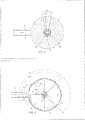
- the fluid intake port 112 is formed in the lower wall segment 102 and is inclined at an angle so as to permit the fluid stream in the lower space 116 to flow in a clockwise direction along the lower wall segment 102 (see Fig. 4 ) .
- the fluid intake port 112 can be varied in number depending on design requirements.
- the lower wall segment 102 has three fluid intake ports 112.
- An angle between the internal port (113b) and each of the fluid intake ports 112 relative to the central axis (C) or the shaft axis (S) is about 45°, 135°, or 225°(see Figs. 1 and 4 ).
- the three fluid intake ports 112 are referred to hereinafter as a port at 45°, a port at 135°, and a port at 225°.
- the port 112 at 45° is on the upper side
- the port 112 at 135° is substantially opposite the elongated handle 12
- the port 112 at 225° is on the lower side for drawing out excess saliva or water during dental procedures.
- the mounting frame 1 further includes a channel 15 which is disposed upstream of the internal port (113b), and which extends from the internal port (113b) along the lower wall segment 102 to terminate at an entry port 151 which is disposed to ensure that the fluid stream flows along the lower wall segment 102 into the channel 15.
- the lower space 116 is almost an enclosed space except where it communicates with the internal port 113b and the fluid intake ports 112, and because of the inclined configuration of the channel 15 and the fluid intake ports 112, the fluid stream can be steadily generated and is sufficient to drive the blades 132 to rotate to thereby rotate the mirror member 2.
- the mirror member 2 because the mirror member 2 is driven to rotate by virtue of the fluid stream, it can be immediately stopped once the reflecting surface 211 of the mirror member 2 is in contact with, for example, the tongue or teeth of a patient.
- the mirror member 2 in this embodiment is not connected to an electrical power source, there is no risk of an electric shock.
- the mirror member 2 in this embodiment is driven by the fluid stream, in other embodiments, the mirror member 2 may be driven by, for example, electric power.
- the mouth mirror apparatus can be disassembled for cleaning and sterilization.
- the bottom cover wall 14 is removed from the lower wall segment 102 of the surrounding wall 10, and the fastening member 3 is loosened.
- a pointed object such as a pin is inserted into a hole of the hub 130 to push the rotatable shaft 22 upwardly so that the mirror member 2 can be removed.
- Fig. 6 shows a part of a mouth mirror apparatus according to a second embodiment of the disclosure.
- the second embodiment is similar to the first embodiment except that, in the second embodiment, the elongated handle 12 is formed with an opening 122 which is in fluid communication with the passage 121, and which is disposed downstream of the internal port 113b (see Fig. 4 ).
- the mouth mirror apparatus further includes a gate member 16 which is mounted on the elongated handle 12, and which is displaceable between a closed position, where the opening 122 is closed by the gate member 16 to permit generation of the fluid stream, and an open position, where the opening 122 is open to interrupt the drawing of the fluid through the fluid intake ports 112.
- the gate member 16 is a sleeve which is rotatably sleeved on the elongated handle 12, and which has a through bore 161. When the gate member 16 is displaced to the open position, the through bore 16 is in register with the opening 122. In other embodiments, the gate member 16 may be a slidable cover.
- the opening 122 may have a dimension larger than that of each fluid intake port 112.
- the dentist can displace the gate member 16 to the open position so as to facilitate removal of the liquid.
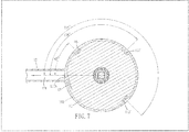
- Fig. 7 shows a part of a mouth mirror apparatus according to a third embodiment of the disclosure.
- the third embodiment is similar to the first embodiment except that, in the third embodiment, each of the three fluid intake ports 112' is formed in the major wall 11 and is disposed adjacent to the periphery 111 of the major wall 11 so as to permit the fluid stream to flow along the lower wall segment 102.
- an angle between the internal port 113b and each of the fluid intake ports 112 relative to the central axis (C) or the shaft axis (S) (the central axis (C) and the shaft axis (S) are shown in Fig. 1 ) is about 45°, 135°, or 225°.
Landscapes
- Health & Medical Sciences (AREA)
- Life Sciences & Earth Sciences (AREA)
- Dentistry (AREA)
- Veterinary Medicine (AREA)
- Public Health (AREA)
- General Health & Medical Sciences (AREA)
- Animal Behavior & Ethology (AREA)
- Surgery (AREA)
- Engineering & Computer Science (AREA)
- Oral & Maxillofacial Surgery (AREA)
- Epidemiology (AREA)
- Nuclear Medicine, Radiotherapy & Molecular Imaging (AREA)
- Optics & Photonics (AREA)
- Heart & Thoracic Surgery (AREA)
- Medical Informatics (AREA)
- Molecular Biology (AREA)
- Radiology & Medical Imaging (AREA)
- Pathology (AREA)
- Biomedical Technology (AREA)
- Biophysics (AREA)
- Physics & Mathematics (AREA)
- Water Supply & Treatment (AREA)
- Dental Tools And Instruments Or Auxiliary Dental Instruments (AREA)
- Endoscopes (AREA)
- Rear-View Mirror Devices That Are Mounted On The Exterior Of The Vehicle (AREA)
- Mirrors, Picture Frames, Photograph Stands, And Related Fastening Devices (AREA)
Claims (9)
- Mundspiegelvorrichtung, umfassend:einen Befestigungsrahmen (1), der eine Mittelachse (C) definiert und umfassteine Hauptwand (11) mit einem Umfang (111),eine umgebende Wand (10), die ein oberes Wandsegment (101) aufweist, das sich von dem Umfang (111) nach oben erstreckt, sodass es die Mittelachse (C) umgibt und an einem oberen Ende (103) abschließt und das zusammen mit der Hauptwand (11) einen oberen Raum (115) definiert, wobei das obere Wandsegment (101) einen Saugport (113a) aufweist, der konfiguriert ist, Flüssigkeit in den oberen Raum herauszuziehen, undein unteres Wandsegment (102), das sich von dem Umfang (111) nach unten erstreckt, sodass es die Mittelachse (C) umgibt und an einem unteren Ende (104) abschließt und das zusammen mit der Hauptwand (11) einen unteren Raum (116) definiert undeine untere Abdeckwand (14), die an dem unteren Ende (104) des unteren Wandsegments (102) befestigt ist, sodass sie den unteren Raum (116) umschließt;ein länglicher Griff (12), der darin einen Durchgang (121) definiert;ein Spiegelelement (2), das an der Hauptwand (11) drehbar befestigt ist und einen Spiegelkörper (21) umfasst, der in dem oberen Raum (115) angeordnet ist und eine reflektierende Fläche (211) aufweist, die nach oben zeigt, und eine drehbare Welle (22), die sich vom Spiegelkörper (21) nach unten durch die Hauptwand (11) in den unteren Raum (116) erstreckt, sodass sie derart angetrieben wird, dass sie sich um die Wellenachse (S) dreht; undein Antriebselement (13), das mit dieser drehbaren Welle (22) gekoppelt ist, um die drehbare Welle (22) anzutreiben, sodass sie sich um die Wellenachse (S) dreht, wobeider längliche Griff (12) einen Fluidauslassport (120) stromabwärts des Durchgangs (121) aufweist und mit der umgebenden Wand (10) verbunden ist, sodass der Durchgang (121) stromabwärts des Saugports (113a) angeordnet ist;das Antriebselement (13) im unteren Raum (116) drehbar angeordnet und auf der drehbaren Welle (22) befestigt ist, um der drehbaren Welle (22) zu erlauben, sich damit zu drehen, wobei das Antriebselement (13) mehrere Schaufeln (132) umfasst, die winklig zueinander über die Wellenachse (S) versetzt sind;das untere Wandsegment (102) einen inneren Port (113b) aufweist, der den Durchgang (121) mit dem unteren Raum (116) in Verbindung bringt; undder Befestigungsrahmen (1) mit mindestens einem Fluideinlassport (112; 112') gebildet ist, der konfiguriert ist, überschüssigen Speichel oder überschüssiges Wasser während zahnärztlicher Behandlungen herauszuziehen, wobei der Fluideinlassport stromaufwärts des inneren Ports (113b) angeordnet ist, sodass einem Fluidstrom erlaubt wird, durch den Fluideinlassport (112, 112') in den unteren Raum (116) gezogen zu werden, um in Richtung des inneren Ports (113b) zu strömen und die Schaufeln (132) zu zwingen, sich um die Wellenachse (S) zu drehen und dadurch das Spiegelelement (2) zu drehen.
- Mundspiegelvorrichtung nach Anspruch 1, dadurch gekennzeichnet, dass das Spiegelelement (2) lösbar an der Hauptwand (11) befestigt ist.
- Mundspiegelvorrichtung nach Anspruch 1, dadurch gekennzeichnet, dass der Fluideinlassport (112) in dem unteren Wandsegment (102) gebildet und in einem Winkel geneigt ist, um dem Fluidstrom zu erlauben, entlang dem unteren Wandsegment (102) zu strömen.
- Mundspiegelvorrichtung nach Anspruch 1, dadurch gekennzeichnet, dass der Fluideinlassport (112') in der Hauptwand (11) gebildet und neben dem Umfang (111) der Hauptwand (11) angeordnet ist, um dem Fluidstrom zu erlauben, entlang dem unteren Wandsegment (102) zu strömen.
- Mundspiegelvorrichtung nach Anspruch 1, dadurch gekennzeichnet, dass der Befestigungsrahmen (1) ferner einen Kanal (15) umfasst, der stromaufwärts des inneren Ports (113b) angeordnet ist und sich von dem inneren Port (113b) entlang dem unteren Wandsegment (102) erstreckt, sodass er an einem Eintrittsport (151) abschließt, der angeordnet ist, um sicherzustellen, dass der Fluidstrom entlang dem unteren Wandsegment (102) in den Kanal (15) strömt.
- Mundspiegelvorrichtung nach Anspruch 1, dadurch gekennzeichnet, dass die untere Abdeckwand (14) lösbar an dem unteren Ende (104) des unteren Wandsegments (102) befestigt ist.
- Mundspiegelvorrichtung nach Anspruch 6, dadurch gekennzeichnet, dass das Antriebselement (13) ferner eine Nabe (130) aufweist, an der die Schaufeln (132) befestigt sind, die Nabe (130) an der drehbaren Welle (22) mit einer Hülse versehen ist, die Hauptwand (11) ein Durchgangsloch (110) aufweist, das einen oberen Lochabschnitt mit größerem Durchmesser (110a) und einen unteren Lochabschnitt mit kleinerem Durchmesser (110b) aufweist, der untere Lochabschnitt mit kleinerem Durchmesser (110b) und der obere Lochabschnitt mit größerem Durchmesser (110a) eine Absatzfläche (110c) dazwischen definieren,
wobei die Mundspiegelvorrichtung ferner umfasst
eine Lagereinheit (131), die auf der Absatzfläche (110c) und zwischen der Hauptwand (11) und der Nabe (130) angeordnet ist, um der Nabe (130) zu erlauben, sich relativ zu der Hauptwand (11) zu drehen, und
ein Befestigungselement (3) mit einem Widerlagerkopf (31) und einem Gewindeschaft (32), sodass, wenn der Gewindeschaft (32) in die drehbare Welle (22) entlang der Wellenachse (S) geschraubt ist, der Widerlagerkopf (31) in anliegendem Eingriff mit der Nabe (130) als auch mit der drehbaren Welle (22) gebracht wird, um dadurch eine Kodrehung des Antriebselements (13) und des Spiegelelements (2) zu erlauben. - Mundspiegelvorrichtung nach Anspruch 1, dadurch gekennzeichnet, dass der längliche Griff (12) mit einer Öffnung (122) gebildet ist, die in Fluidverbindung mit dem Durchgang (121) ist, und die stromabwärts des inneren Ports (113b) angeordnet ist, wobei die Mundspiegelvorrichtung, ferner ein Sperrenelement (16) umfasst, das an dem länglichen Griff (12) befestigt ist und das zwischen einer geschlossenen Stellung, in der die Öffnung (122) durch das Sperrenelement (16) geschlossen ist, um eine Erzeugung des Fluidstroms zu erlauben, und einer offenen Stellung, in der die Öffnung (122) nicht geschlossen ist, um das Ziehen des Fluids durch den Fluideinlassport (112, 112') zu unterbrechen, verschiebbar ist.
- Mundspiegelvorrichtung nach Anspruch 1, dadurch gekennzeichnet, dass der längliche Griff (12) einen rohrförmigen Endabschnitt (123) umfasst, welcher den Fluidauslassport (120) definiert und eine gezahnte Außenfläche (1231) aufweist, wobei der Fluidauslassport (120) konfiguriert ist, nach unten zu zeigen.
Priority Applications (1)
| Application Number | Priority Date | Filing Date | Title |
|---|---|---|---|
| PL15197220T PL3103382T3 (pl) | 2015-06-11 | 2015-12-01 | Urządzenie z lusterkiem stomatologicznym |
Applications Claiming Priority (1)
| Application Number | Priority Date | Filing Date | Title |
|---|---|---|---|
| TW104118917A TWI536948B (zh) | 2015-06-11 | 2015-06-11 | 口鏡裝置 |
Publications (2)
| Publication Number | Publication Date |
|---|---|
| EP3103382A1 EP3103382A1 (de) | 2016-12-14 |
| EP3103382B1 true EP3103382B1 (de) | 2018-02-07 |
Family
ID=54780137
Family Applications (1)
| Application Number | Title | Priority Date | Filing Date |
|---|---|---|---|
| EP15197220.5A Active EP3103382B1 (de) | 2015-06-11 | 2015-12-01 | Mundspiegelvorrichtung |
Country Status (11)
| Country | Link |
|---|---|
| US (1) | US9675240B2 (de) |
| EP (1) | EP3103382B1 (de) |
| JP (1) | JP6139648B2 (de) |
| KR (1) | KR101811523B1 (de) |
| BR (1) | BR102016010553B1 (de) |
| CA (1) | CA2924566C (de) |
| ES (1) | ES2667734T3 (de) |
| HU (1) | HUE037390T2 (de) |
| PL (1) | PL3103382T3 (de) |
| PT (1) | PT3103382T (de) |
| TW (1) | TWI536948B (de) |
Families Citing this family (5)
| Publication number | Priority date | Publication date | Assignee | Title |
|---|---|---|---|---|
| EP3735167A4 (de) * | 2018-01-02 | 2021-09-08 | Dentaleer Ltd. | Spiegelanordnung zur verwendung in der zahnheilkunde |
| JP6652983B2 (ja) * | 2018-02-27 | 2020-02-26 | 勝之 山▲崎▼ | 口腔鏡補助装置 |
| TWI718071B (zh) * | 2020-06-18 | 2021-02-01 | 汪昇朋 | 出氣式口鏡裝置 |
| KR200496810Y1 (ko) | 2021-04-12 | 2023-04-28 | 이재광 | 발 수용 커트보 |
| CN113349721B (zh) * | 2021-06-29 | 2024-10-29 | 佛山市登拓医疗器械有限公司 | 一种口腔内窥镜 |
Family Cites Families (11)
| Publication number | Priority date | Publication date | Assignee | Title |
|---|---|---|---|---|
| CH364866A (fr) | 1960-10-19 | 1962-10-15 | Sic Products Ltd | Miroir rotatif |
| NO127896B (de) * | 1972-04-17 | 1973-09-03 | H Holstad | |
| JPS5464895A (en) | 1977-10-14 | 1979-05-25 | Peel Graham Arthur | Dental instrument |
| US4261637A (en) * | 1979-06-18 | 1981-04-14 | King Bernard G | Reciprocating mirror device |
| US4408991A (en) | 1981-12-14 | 1983-10-11 | Engel Joseph R | Self-cleaning mirror |
| US5449290A (en) | 1994-06-27 | 1995-09-12 | Reitz; Georg | Dental mirror incorporating air flow |
| SE507193C2 (sv) * | 1997-05-12 | 1998-04-20 | Stefan Gunnarsson | Självrengörande roterande tandläkarspegel |
| JP2001061779A (ja) * | 1999-06-22 | 2001-03-13 | Nonomura Tomosuke | 明視界装置付き歯科用ミラー |
| US6575744B1 (en) | 2002-03-04 | 2003-06-10 | Yoshiki Oshida | Mirror |
| CN1883373A (zh) | 2005-06-24 | 2006-12-27 | 上海雷硕医疗器械有限公司 | 一种用于一次性牙镜的镜面离心清洁装置 |
| EP2181643A1 (de) | 2008-10-30 | 2010-05-05 | Dental Care Nordic AB | Instrument für zahnmedizinische Zwecke mit einem Spiegel |
-
2015
- 2015-06-11 TW TW104118917A patent/TWI536948B/zh active
- 2015-11-06 US US14/935,019 patent/US9675240B2/en active Active
- 2015-12-01 ES ES15197220.5T patent/ES2667734T3/es active Active
- 2015-12-01 EP EP15197220.5A patent/EP3103382B1/de active Active
- 2015-12-01 PT PT151972205T patent/PT3103382T/pt unknown
- 2015-12-01 HU HUE15197220A patent/HUE037390T2/hu unknown
- 2015-12-01 PL PL15197220T patent/PL3103382T3/pl unknown
- 2015-12-21 JP JP2015248361A patent/JP6139648B2/ja active Active
-
2016
- 2016-03-22 CA CA2924566A patent/CA2924566C/en active Active
- 2016-05-10 BR BR102016010553-6A patent/BR102016010553B1/pt active IP Right Grant
- 2016-05-12 KR KR1020160058133A patent/KR101811523B1/ko active Active
Non-Patent Citations (1)
| Title |
|---|
| None * |
Also Published As
| Publication number | Publication date |
|---|---|
| TWI536948B (zh) | 2016-06-11 |
| BR102016010553B1 (pt) | 2022-09-20 |
| BR102016010553A2 (pt) | 2016-12-27 |
| US9675240B2 (en) | 2017-06-13 |
| CA2924566C (en) | 2018-02-20 |
| KR101811523B1 (ko) | 2018-01-25 |
| PL3103382T3 (pl) | 2018-07-31 |
| US20160360957A1 (en) | 2016-12-15 |
| JP2017000704A (ja) | 2017-01-05 |
| PT3103382T (pt) | 2018-05-09 |
| HUE037390T2 (hu) | 2018-09-28 |
| KR20160146524A (ko) | 2016-12-21 |
| TW201642799A (zh) | 2016-12-16 |
| JP6139648B2 (ja) | 2017-05-31 |
| EP3103382A1 (de) | 2016-12-14 |
| ES2667734T3 (es) | 2018-05-14 |
| BR102016010553A8 (pt) | 2021-09-14 |
| CA2924566A1 (en) | 2016-12-11 |
Similar Documents
| Publication | Publication Date | Title |
|---|---|---|
| EP3103382B1 (de) | Mundspiegelvorrichtung | |
| US8092217B2 (en) | Suckback prevention device for single use high-speed turbine dental drill handpiece | |
| US5334013A (en) | High speed dental drill with positive pressure air drive | |
| JP2006507031A (ja) | 外科用ハンドピース及びこの外科用ハンドピースに取り付けられ駆動され、かつ動力駆動外科用器具とともに使用する切除アクセサリ | |
| US3092908A (en) | Aspirating dental drill | |
| US20150216622A1 (en) | Ergonomically optimized, in-line water valve assembly for use with a dental handpiece | |
| US20230149138A1 (en) | Cheek retractor | |
| US3624905A (en) | Water-cooled dental cutting member and handpiece for use therewith | |
| WO1998051233A1 (en) | Self-cleaning rotating dentist's mirror | |
| US11439487B2 (en) | Systems and methods for an evacuator adapter | |
| CN209091339U (zh) | 一种儿童耳鼻喉科检查镜 | |
| CN206508045U (zh) | 一次性高速涡轮牙钻手机零回吸装置 | |
| JP5723163B2 (ja) | 手術用又は歯科用ハンドピース用の異物を除去する遠心偏向装置 | |
| CN209529085U (zh) | 口镜装置 | |
| US3060581A (en) | Dental handpiece with removable turbine-and-bearing assembly and liquid cooled burr | |
| CN113812909B (zh) | 出气式口镜装置 | |
| CN106344180A (zh) | 一次性高速涡轮牙钻手机零回吸装置 | |
| HK1230462A1 (en) | Mouth mirror apparatus | |
| TW202200090A (zh) | 出氣式口鏡裝置 | |
| EP1402841A1 (de) | Zahnärztlisches Handstück | |
| CN206745456U (zh) | 一种牙科手机专用电机的气流冷却系统 | |
| CN209137518U (zh) | 一种一次性吸引器头 | |
| HK1230462B (zh) | 口镜装置 | |
| IT202000008218A1 (it) | Dispositivo schermante per riunito dentale e riunito dentale comprendente detto dispositivo schermante. | |
| JP2017099704A (ja) | 歯科用ハンドピース |
Legal Events
| Date | Code | Title | Description |
|---|---|---|---|
| PUAI | Public reference made under article 153(3) epc to a published international application that has entered the european phase |
Free format text: ORIGINAL CODE: 0009012 |
|
| STAA | Information on the status of an ep patent application or granted ep patent |
Free format text: STATUS: THE APPLICATION HAS BEEN PUBLISHED |
|
| AK | Designated contracting states |
Kind code of ref document: A1 Designated state(s): AL AT BE BG CH CY CZ DE DK EE ES FI FR GB GR HR HU IE IS IT LI LT LU LV MC MK MT NL NO PL PT RO RS SE SI SK SM TR |
|
| AX | Request for extension of the european patent |
Extension state: BA ME |
|
| STAA | Information on the status of an ep patent application or granted ep patent |
Free format text: STATUS: REQUEST FOR EXAMINATION WAS MADE |
|
| 17P | Request for examination filed |
Effective date: 20170228 |
|
| RBV | Designated contracting states (corrected) |
Designated state(s): AL AT BE BG CH CY CZ DE DK EE ES FI FR GB GR HR HU IE IS IT LI LT LU LV MC MK MT NL NO PL PT RO RS SE SI SK SM TR |
|
| REG | Reference to a national code |
Ref country code: DE Ref legal event code: R079 Ref document number: 602015007913 Country of ref document: DE Free format text: PREVIOUS MAIN CLASS: A61B0001253000 Ipc: A61C0017060000 |
|
| GRAP | Despatch of communication of intention to grant a patent |
Free format text: ORIGINAL CODE: EPIDOSNIGR1 |
|
| STAA | Information on the status of an ep patent application or granted ep patent |
Free format text: STATUS: GRANT OF PATENT IS INTENDED |
|
| RIC1 | Information provided on ipc code assigned before grant |
Ipc: A61B 1/253 20060101ALI20170921BHEP Ipc: A61C 17/06 20060101AFI20170921BHEP |
|
| INTG | Intention to grant announced |
Effective date: 20171017 |
|
| GRAS | Grant fee paid |
Free format text: ORIGINAL CODE: EPIDOSNIGR3 |
|
| GRAA | (expected) grant |
Free format text: ORIGINAL CODE: 0009210 |
|
| STAA | Information on the status of an ep patent application or granted ep patent |
Free format text: STATUS: THE PATENT HAS BEEN GRANTED |
|
| AK | Designated contracting states |
Kind code of ref document: B1 Designated state(s): AL AT BE BG CH CY CZ DE DK EE ES FI FR GB GR HR HU IE IS IT LI LT LU LV MC MK MT NL NO PL PT RO RS SE SI SK SM TR |
|
| REG | Reference to a national code |
Ref country code: GB Ref legal event code: FG4D |
|
| REG | Reference to a national code |
Ref country code: AT Ref legal event code: REF Ref document number: 968494 Country of ref document: AT Kind code of ref document: T Effective date: 20180215 Ref country code: CH Ref legal event code: EP |
|
| REG | Reference to a national code |
Ref country code: IE Ref legal event code: FG4D |
|
| REG | Reference to a national code |
Ref country code: DE Ref legal event code: R096 Ref document number: 602015007913 Country of ref document: DE |
|
| REG | Reference to a national code |
Ref country code: RO Ref legal event code: EPE |
|
| REG | Reference to a national code |
Ref country code: SE Ref legal event code: TRGR |
|
| REG | Reference to a national code |
Ref country code: PT Ref legal event code: SC4A Ref document number: 3103382 Country of ref document: PT Date of ref document: 20180509 Kind code of ref document: T Free format text: AVAILABILITY OF NATIONAL TRANSLATION Effective date: 20180427 |
|
| REG | Reference to a national code |
Ref country code: ES Ref legal event code: FG2A Ref document number: 2667734 Country of ref document: ES Kind code of ref document: T3 Effective date: 20180514 |
|
| REG | Reference to a national code |
Ref country code: NL Ref legal event code: FP |
|
| PG25 | Lapsed in a contracting state [announced via postgrant information from national office to epo] |
Ref country code: CY Free format text: LAPSE BECAUSE OF FAILURE TO SUBMIT A TRANSLATION OF THE DESCRIPTION OR TO PAY THE FEE WITHIN THE PRESCRIBED TIME-LIMIT Effective date: 20180207 Ref country code: FI Free format text: LAPSE BECAUSE OF FAILURE TO SUBMIT A TRANSLATION OF THE DESCRIPTION OR TO PAY THE FEE WITHIN THE PRESCRIBED TIME-LIMIT Effective date: 20180207 Ref country code: LT Free format text: LAPSE BECAUSE OF FAILURE TO SUBMIT A TRANSLATION OF THE DESCRIPTION OR TO PAY THE FEE WITHIN THE PRESCRIBED TIME-LIMIT Effective date: 20180207 Ref country code: HR Free format text: LAPSE BECAUSE OF FAILURE TO SUBMIT A TRANSLATION OF THE DESCRIPTION OR TO PAY THE FEE WITHIN THE PRESCRIBED TIME-LIMIT Effective date: 20180207 Ref country code: NO Free format text: LAPSE BECAUSE OF FAILURE TO SUBMIT A TRANSLATION OF THE DESCRIPTION OR TO PAY THE FEE WITHIN THE PRESCRIBED TIME-LIMIT Effective date: 20180507 |
|
| PG25 | Lapsed in a contracting state [announced via postgrant information from national office to epo] |
Ref country code: BG Free format text: LAPSE BECAUSE OF FAILURE TO SUBMIT A TRANSLATION OF THE DESCRIPTION OR TO PAY THE FEE WITHIN THE PRESCRIBED TIME-LIMIT Effective date: 20180507 Ref country code: RS Free format text: LAPSE BECAUSE OF FAILURE TO SUBMIT A TRANSLATION OF THE DESCRIPTION OR TO PAY THE FEE WITHIN THE PRESCRIBED TIME-LIMIT Effective date: 20180207 Ref country code: LV Free format text: LAPSE BECAUSE OF FAILURE TO SUBMIT A TRANSLATION OF THE DESCRIPTION OR TO PAY THE FEE WITHIN THE PRESCRIBED TIME-LIMIT Effective date: 20180207 Ref country code: IS Free format text: LAPSE BECAUSE OF FAILURE TO SUBMIT A TRANSLATION OF THE DESCRIPTION OR TO PAY THE FEE WITHIN THE PRESCRIBED TIME-LIMIT Effective date: 20180607 |
|
| REG | Reference to a national code |
Ref country code: HU Ref legal event code: AG4A Ref document number: E037390 Country of ref document: HU |
|
| REG | Reference to a national code |
Ref country code: FR Ref legal event code: PLFP Year of fee payment: 4 |
|
| PG25 | Lapsed in a contracting state [announced via postgrant information from national office to epo] |
Ref country code: EE Free format text: LAPSE BECAUSE OF FAILURE TO SUBMIT A TRANSLATION OF THE DESCRIPTION OR TO PAY THE FEE WITHIN THE PRESCRIBED TIME-LIMIT Effective date: 20180207 Ref country code: AL Free format text: LAPSE BECAUSE OF FAILURE TO SUBMIT A TRANSLATION OF THE DESCRIPTION OR TO PAY THE FEE WITHIN THE PRESCRIBED TIME-LIMIT Effective date: 20180207 |
|
| REG | Reference to a national code |
Ref country code: GR Ref legal event code: EP Ref document number: 20180401181 Country of ref document: GR Effective date: 20181012 Ref country code: DE Ref legal event code: R097 Ref document number: 602015007913 Country of ref document: DE |
|
| PG25 | Lapsed in a contracting state [announced via postgrant information from national office to epo] |
Ref country code: SM Free format text: LAPSE BECAUSE OF FAILURE TO SUBMIT A TRANSLATION OF THE DESCRIPTION OR TO PAY THE FEE WITHIN THE PRESCRIBED TIME-LIMIT Effective date: 20180207 Ref country code: DK Free format text: LAPSE BECAUSE OF FAILURE TO SUBMIT A TRANSLATION OF THE DESCRIPTION OR TO PAY THE FEE WITHIN THE PRESCRIBED TIME-LIMIT Effective date: 20180207 Ref country code: SK Free format text: LAPSE BECAUSE OF FAILURE TO SUBMIT A TRANSLATION OF THE DESCRIPTION OR TO PAY THE FEE WITHIN THE PRESCRIBED TIME-LIMIT Effective date: 20180207 |
|
| PLBE | No opposition filed within time limit |
Free format text: ORIGINAL CODE: 0009261 |
|
| STAA | Information on the status of an ep patent application or granted ep patent |
Free format text: STATUS: NO OPPOSITION FILED WITHIN TIME LIMIT |
|
| 26N | No opposition filed |
Effective date: 20181108 |
|
| PG25 | Lapsed in a contracting state [announced via postgrant information from national office to epo] |
Ref country code: SI Free format text: LAPSE BECAUSE OF FAILURE TO SUBMIT A TRANSLATION OF THE DESCRIPTION OR TO PAY THE FEE WITHIN THE PRESCRIBED TIME-LIMIT Effective date: 20180207 |
|
| PG25 | Lapsed in a contracting state [announced via postgrant information from national office to epo] |
Ref country code: LU Free format text: LAPSE BECAUSE OF NON-PAYMENT OF DUE FEES Effective date: 20181201 Ref country code: MC Free format text: LAPSE BECAUSE OF FAILURE TO SUBMIT A TRANSLATION OF THE DESCRIPTION OR TO PAY THE FEE WITHIN THE PRESCRIBED TIME-LIMIT Effective date: 20180207 |
|
| REG | Reference to a national code |
Ref country code: IE Ref legal event code: MM4A |
|
| PG25 | Lapsed in a contracting state [announced via postgrant information from national office to epo] |
Ref country code: IE Free format text: LAPSE BECAUSE OF NON-PAYMENT OF DUE FEES Effective date: 20181201 |
|
| PG25 | Lapsed in a contracting state [announced via postgrant information from national office to epo] |
Ref country code: MT Free format text: LAPSE BECAUSE OF NON-PAYMENT OF DUE FEES Effective date: 20181201 |
|
| PGFP | Annual fee paid to national office [announced via postgrant information from national office to epo] |
Ref country code: IT Payment date: 20191023 Year of fee payment: 5 |
|
| PG25 | Lapsed in a contracting state [announced via postgrant information from national office to epo] |
Ref country code: MK Free format text: LAPSE BECAUSE OF NON-PAYMENT OF DUE FEES Effective date: 20180207 |
|
| PG25 | Lapsed in a contracting state [announced via postgrant information from national office to epo] |
Ref country code: IT Free format text: LAPSE BECAUSE OF NON-PAYMENT OF DUE FEES Effective date: 20201201 |
|
| PGFP | Annual fee paid to national office [announced via postgrant information from national office to epo] |
Ref country code: RO Payment date: 20211118 Year of fee payment: 7 |
|
| PGFP | Annual fee paid to national office [announced via postgrant information from national office to epo] |
Ref country code: HU Payment date: 20211110 Year of fee payment: 7 |
|
| REG | Reference to a national code |
Ref country code: AT Ref legal event code: UEP Ref document number: 968494 Country of ref document: AT Kind code of ref document: T Effective date: 20180207 |
|
| P01 | Opt-out of the competence of the unified patent court (upc) registered |
Effective date: 20230522 |
|
| PG25 | Lapsed in a contracting state [announced via postgrant information from national office to epo] |
Ref country code: RO Free format text: LAPSE BECAUSE OF NON-PAYMENT OF DUE FEES Effective date: 20221201 |
|
| PG25 | Lapsed in a contracting state [announced via postgrant information from national office to epo] |
Ref country code: HU Free format text: LAPSE BECAUSE OF NON-PAYMENT OF DUE FEES Effective date: 20221202 |
|
| PGFP | Annual fee paid to national office [announced via postgrant information from national office to epo] |
Ref country code: PT Payment date: 20241111 Year of fee payment: 10 |
|
| PGFP | Annual fee paid to national office [announced via postgrant information from national office to epo] |
Ref country code: DE Payment date: 20241007 Year of fee payment: 10 |
|
| PGFP | Annual fee paid to national office [announced via postgrant information from national office to epo] |
Ref country code: PL Payment date: 20241106 Year of fee payment: 10 Ref country code: NL Payment date: 20241224 Year of fee payment: 10 Ref country code: BE Payment date: 20241224 Year of fee payment: 10 Ref country code: GR Payment date: 20241219 Year of fee payment: 10 |
|
| PGFP | Annual fee paid to national office [announced via postgrant information from national office to epo] |
Ref country code: GB Payment date: 20241008 Year of fee payment: 10 |
|
| PGFP | Annual fee paid to national office [announced via postgrant information from national office to epo] |
Ref country code: FR Payment date: 20241008 Year of fee payment: 10 Ref country code: AT Payment date: 20241218 Year of fee payment: 10 |
|
| PGFP | Annual fee paid to national office [announced via postgrant information from national office to epo] |
Ref country code: CZ Payment date: 20241113 Year of fee payment: 10 |
|
| PGFP | Annual fee paid to national office [announced via postgrant information from national office to epo] |
Ref country code: SE Payment date: 20241009 Year of fee payment: 10 |
|
| PGFP | Annual fee paid to national office [announced via postgrant information from national office to epo] |
Ref country code: TR Payment date: 20241113 Year of fee payment: 10 |
|
| PGFP | Annual fee paid to national office [announced via postgrant information from national office to epo] |
Ref country code: ES Payment date: 20250114 Year of fee payment: 10 |
|
| PGFP | Annual fee paid to national office [announced via postgrant information from national office to epo] |
Ref country code: CH Payment date: 20250101 Year of fee payment: 10 |