EP3103302B1 - Procédé et appareil permettant à un processeur de générer des signaux de commande en pipeline - Google Patents
Procédé et appareil permettant à un processeur de générer des signaux de commande en pipeline Download PDFInfo
- Publication number
- EP3103302B1 EP3103302B1 EP15746535.2A EP15746535A EP3103302B1 EP 3103302 B1 EP3103302 B1 EP 3103302B1 EP 15746535 A EP15746535 A EP 15746535A EP 3103302 B1 EP3103302 B1 EP 3103302B1
- Authority
- EP
- European Patent Office
- Prior art keywords
- instructions
- group
- instruction
- processor
- chaining
- Prior art date
- Legal status (The legal status is an assumption and is not a legal conclusion. Google has not performed a legal analysis and makes no representation as to the accuracy of the status listed.)
- Active
Links
- 238000000034 method Methods 0.000 title claims description 42
- 230000015654 memory Effects 0.000 claims description 24
- 238000012545 processing Methods 0.000 claims description 12
- 230000006870 function Effects 0.000 claims description 4
- 239000000284 extract Substances 0.000 claims description 3
- 238000005457 optimization Methods 0.000 description 9
- 230000003068 static effect Effects 0.000 description 8
- 238000010586 diagram Methods 0.000 description 7
- 230000000694 effects Effects 0.000 description 5
- 235000000434 Melocanna baccifera Nutrition 0.000 description 3
- 241001497770 Melocanna baccifera Species 0.000 description 3
- 230000008901 benefit Effects 0.000 description 3
- 238000004590 computer program Methods 0.000 description 3
- 230000001419 dependent effect Effects 0.000 description 3
- 230000009191 jumping Effects 0.000 description 3
- 230000003287 optical effect Effects 0.000 description 3
- 238000013459 approach Methods 0.000 description 2
- 238000013461 design Methods 0.000 description 2
- 230000008569 process Effects 0.000 description 2
- 241000761456 Nops Species 0.000 description 1
- 101100534231 Xenopus laevis src-b gene Proteins 0.000 description 1
- 238000003491 array Methods 0.000 description 1
- 230000005540 biological transmission Effects 0.000 description 1
- 230000015556 catabolic process Effects 0.000 description 1
- 150000001875 compounds Chemical class 0.000 description 1
- 238000007796 conventional method Methods 0.000 description 1
- 238000013500 data storage Methods 0.000 description 1
- 238000006731 degradation reaction Methods 0.000 description 1
- 238000001514 detection method Methods 0.000 description 1
- 239000000796 flavoring agent Substances 0.000 description 1
- 235000019634 flavors Nutrition 0.000 description 1
- 230000007274 generation of a signal involved in cell-cell signaling Effects 0.000 description 1
- 230000006872 improvement Effects 0.000 description 1
- 239000004973 liquid crystal related substance Substances 0.000 description 1
- 108010020615 nociceptin receptor Proteins 0.000 description 1
- 239000000126 substance Substances 0.000 description 1
- 230000001360 synchronised effect Effects 0.000 description 1
Images


Classifications
-
- G—PHYSICS
- G06—COMPUTING; CALCULATING OR COUNTING
- G06F—ELECTRIC DIGITAL DATA PROCESSING
- G06F9/00—Arrangements for program control, e.g. control units
- G06F9/06—Arrangements for program control, e.g. control units using stored programs, i.e. using an internal store of processing equipment to receive or retain programs
- G06F9/30—Arrangements for executing machine instructions, e.g. instruction decode
- G06F9/30145—Instruction analysis, e.g. decoding, instruction word fields
-
- G—PHYSICS
- G06—COMPUTING; CALCULATING OR COUNTING
- G06F—ELECTRIC DIGITAL DATA PROCESSING
- G06F9/00—Arrangements for program control, e.g. control units
- G06F9/06—Arrangements for program control, e.g. control units using stored programs, i.e. using an internal store of processing equipment to receive or retain programs
- G06F9/30—Arrangements for executing machine instructions, e.g. instruction decode
- G06F9/38—Concurrent instruction execution, e.g. pipeline or look ahead
- G06F9/3818—Decoding for concurrent execution
- G06F9/3822—Parallel decoding, e.g. parallel decode units
-
- G—PHYSICS
- G06—COMPUTING; CALCULATING OR COUNTING
- G06F—ELECTRIC DIGITAL DATA PROCESSING
- G06F9/00—Arrangements for program control, e.g. control units
- G06F9/06—Arrangements for program control, e.g. control units using stored programs, i.e. using an internal store of processing equipment to receive or retain programs
- G06F9/30—Arrangements for executing machine instructions, e.g. instruction decode
- G06F9/38—Concurrent instruction execution, e.g. pipeline or look ahead
- G06F9/3836—Instruction issuing, e.g. dynamic instruction scheduling or out of order instruction execution
- G06F9/3853—Instruction issuing, e.g. dynamic instruction scheduling or out of order instruction execution of compound instructions
-
- G—PHYSICS
- G06—COMPUTING; CALCULATING OR COUNTING
- G06F—ELECTRIC DIGITAL DATA PROCESSING
- G06F9/00—Arrangements for program control, e.g. control units
- G06F9/06—Arrangements for program control, e.g. control units using stored programs, i.e. using an internal store of processing equipment to receive or retain programs
- G06F9/30—Arrangements for executing machine instructions, e.g. instruction decode
- G06F9/38—Concurrent instruction execution, e.g. pipeline or look ahead
- G06F9/3867—Concurrent instruction execution, e.g. pipeline or look ahead using instruction pipelines
Definitions
- Embodiments of the present disclosure relate to a method and apparatus for processing instructions in a microprocessor environment. More specifically, the embodiments relate to a method and an apparatus for enabling dependency information, parallelism information, and performance optimizations to be encoded in a sequence of instructions.
- a processor may decode and employ this information to generate pipeline control signals without the need for complicated inter-instruction dependency checking hardware.
- Instructions within a group of processor instructions in a sequential instruction stream are said to be independent of each other when the input values of the processor instructions are not generated by other processor instructions within the group. In other words, the resulting output of execution of the instruction stream remains the same whether the instructions within the group of processor instructions are evaluated sequentially in order or in parallel or in an out-of-order manner.
- ILP instruction level parallelism
- ILP in an instruction stream
- Current processor architectures attempt to mitigate the effects of these dependencies by employing micro-architectural techniques such as dynamic instruction scheduling, static instruction scheduling, and multiple instruction issue.
- Dynamic instruction scheduling techniques have been widely used in the domain of general purpose processors. However, due to real-time and power constraints, processors in the embedded systems domain have typically used static instruction scheduling techniques.
- FIG. 1 shows a set of instructions stages that may be employed by a typical pipelined processor.
- the first instruction, addi performs an addition of the contents of register r 2 with the immediate value 8.
- IF first stage
- RD second stage
- EX third stage
- WB fourth stage
- Each of the pipeline phases (IF, RD, EX, and WB) are generally executed on a clock boundary.
- the second instruction, muli may be started on the second clock cycle without requiring additional hardware.
- the processing of the second instruction may be overlapped with the first instruction because the resources needed for the IF stage are not needed in the RD stage.
- the IF, RD, EX, and WB stages may be shared but shifted in time.
- Figure 2 shows a complication with the pipeline implementation of Figure 1 .
- the muli instruction requires the result computed by the addi instruction as an operand. Since the write-back (WB) phase has not yet occurred, the process must stall and wait for the execution to complete. The empty cycles the muli must wait for its operands to become available are typically called "bubbles" in the pipeline.
- Typical general purpose processors dynamically determine, using complex dependency checking hardware, whether a decoded instruction has inter-instruction dependencies with the instructions currently executing in a pipeline. This hardware is sometimes known as interlock hardware. If a dependency is detected (also known as a hazard), the instruction issue is stalled until the dependent instruction completes execution and the dependency is resolved. It should be noted that if a processor is capable of forwarding a result from the current instruction's EX stage directly to the next instruction's EX stage, then no bubbles in the pipeline would form. This is termed bypassing or sometimes result forwarding.
- Typical embedded processors may employ exposed pipelines where the programmer or compiler is responsible for ensuring code executes correctly by scheduling the instructions prior to execution such that all inter-instruction dependencies are satisfied. This way of scheduling instructions at compile time is known as static scheduling. With static scheduling and no interlock hardware, NOP (no operation) instructions may need to be inserted into the instruction stream such that an appropriate number of cycles elapse before the register file is read.
- pipelined overlapping instruction execution may be referred to as vertical parallelism.
- horizontal parallelism Another type of parallelism may be referred to as horizontal parallelism.
- horizontal parallelism multiple independent operations may be executed concurrently if there are no dependencies. This is often the case in digital signal processing code and high performance computing programs.
- FIG. 1 is a simplified circuit diagram of a Vector/SIMD processor.
- Processors may exploit horizontal parallelism by issuing multiple independent instructions simultaneously in a single clock cycle.
- Multiple issue processors come in two basic flavors: superscalar processors and VLIW processors. The basic difference between the two types is the manner in which inter-instruction dependencies are resolved and instructions are issued for execution.
- the inter-instruction hazards are detected dynamically at run time in hardware. Once a dependency is resolved, the instruction(s) are issued dynamically.
- Current general purpose processors are typically speculative superscalar processors, which issue a varying number of instructions per clock cycle, perform inter-instruction hazard detection in hardware, issue instructions dynamically once dependencies are resolved, perform out-of-order instruction execution followed by in-order commit, and perform speculative execution of the instruction stream to mitigate the effects of control dependencies.
- VLIW and exposed pipeline architectures typically issue a fixed number of operations formatted as one large instruction. Instruction scheduling is performed statically at compile time or by the programmer. This approach relies on the compiler or programmer to identify hazards and schedule operations since the implementation does not contain hardware to check explicitly for hazards. Embedded processors and digital signal processors typically use very long instruction word (VLIW) techniques.
- VLIW very long instruction word
- VLIW executes all operations within an instruction simultaneously.
- architectures have employed one or more bits within the VLIW instruction field to indicate parallelism explicitly. This permits the execution of the operations within an instruction to be issued serially rather than in parallel.
- the Sandbridge Sandblaster SB3500 microprocessor uses a single bit within its 3-operation compound instruction bundle called the "serial bit" to indicate whether operations within the instruction bundle are required to be executed sequentially. If the serial bit is set, then the operations within the bundle are executed serially. If the serial bit is not set, then the operations must execute in parallel. If one of the operations is a taken branch with the serial bit set, then the remainder of the operations is not executed.
- Texas Instruments The original Texas Instruments TI C6201 microprocessor, as described in " TMS320C64x/C64x+ DSP CPU and Instruction Set - Reference Guide," Literature Number: SPRU732J, Texas Instruments, July 2010 (hereinafter "Texas Instruments"), required 256-bits to be fetched for each VLIW instruction. Texas Instruments termed these 256-bit instructions fetch packets. Texas Instruments subdivided the operation fields into separate 32-bit fields that Texas Instruments referred to as instructions. The execution of these operations within this fetch packet is controlled partially by a bit in each "instruction" called the "p-bit.” The p-bit determines whether the instruction is to be executed in parallel with another instruction.
- instruction i + 1 is to be executed in parallel with (in the same cycle as) instruction i. If the p-bit of instruction i is 0, then instruction i + 1 is executed in the cycle after instruction i.
- the p-bit patterns within a VLIW fetch packet permits the execution of the instructions in a fully parallel, fully serial, or partially serial fashion.
- U.S. Patent 6,260,189 titled, "Compiler-controlled dynamic instruction dispatch in pipelined processors," describes a technique of encoding pipeline dependencies within a code block in a pipeline dependency field in the code block.
- a compiler or programmer needed to identify pipeline dependencies in a plurality of instructions such as Read-After-Write (RAW) hazards, Write-After-Write (WAW) hazards, Write-After-Read (WAR) hazards or predication hazards.
- RAW Read-After-Write
- WAW Write-After-Write
- WAR Write-After-Read
- the processor implemented only those stalls or other corrective measures that were required for hazards actually present in a given block of code as specified in the pipeline dependency field, thereby avoiding the performance degradations which can result when using conventional techniques.
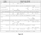
- Figures 4A and 4B show examples of pipeline dependency fields for two different code blocks.
- the code block in Figure 4A has a RAW dependency and the pipeline dependency field indicates this.
- the code block in Figure 4B does not have any data or prediction dependencies.
- US2007233961 discloses a VLIW processor with an early extractor of stop/branch bits of an instruction stream.
- An apparatus is described that decodes the chained bits.
- the processor employs these chaining bits to execute in parallel and with reduced latency as many instructions as possible from groups of chained instructions.
- the chaining bits explicitly encode both inter-instruction dependencies and inter-group dependencies without having to fully decode the instructions. This eliminates the need for complex hardware interlocks that check for and satisfy inter-instruction dependencies in pipelined processor architectures.
- a method and apparatus is described wherein a compiler or programmer identifies parallelism and inter-instruction dependencies and encodes this information using a single bit of the instruction format distributed over a number of instructions. This may be referred to as instruction chaining.
- a processor then reassembles these bits at runtime to determine inter-instruction dependencies and parallelism within the instruction stream. This information is employed by the processor to generate the necessary pipeline control signals to improve execution times or to stall the pipeline to satisfy inter-instruction dependencies without the need for complex dependency checking hardware, long instruction sequences, or complex issue logic. Other types of performance optimizations, such as bypass information, may be encoded into the chained bits.
- Examples of the present disclosure enable a static issue processor to achieve the performance of a dynamic issue processor while keeping the low hardware complexity and low power of a static issue processor. Examples of the present disclosure demonstrate the scalability of the technique to adapt to processors that can issue multiple instructions in a single clock cycle.
- Instruction chaining employs one bit per instruction, referred to hereinafter as the "chaining bit,” to indicate both parallelism and inter-instruction dependencies in a sequence of processor instructions.
- an instruction refers to an independently addressable unit with operation and operand phrases (See Blaaw, page 128). Multiple instructions may be grouped together to form an instruction group that may be fetched together. At runtime, the processor reassembles the chaining bits from the instructions in an instruction group to decode dependencies and parallelism within the instruction stream efficiently without having to decode the individual instructions. This information may be employed to generate necessary pipeline control signals for instruction issue, eliminating the need for complex inter-instruction dependency checking hardware or NOP instructions in pipelined processor architectures.
- This procedure may co-exist with pipeline effects that are not visible to programmers such as long load pipeline stalls, branch resolution, and other long latency operations. Since each instruction is independently addressable, jumping into the middle of an instruction group may be permitted. However, when jumping into the middle of the instruction group, the dependency bits for the entire group need to be reconstructed for chaining bit decoding. If a compiler analyzes the instruction dependencies and generates the chaining bits, then a programmer effectively does not see any pipeline effects and can program the machine without regard to hazards.
- chaining bits may be implementation dependent: their semantics may be interpreted only on the processor for which they were programmed.
- a single-issue pipelined processor may have only two interpretations of one chaining bit.
- a "0" value denotes no chaining and a "1" value denotes that the instruction may be chained with the next instruction.
- the chaining bit may indicate only whether instructions are independent and with or without hazards.
- the logic of the chaining bit may be reversed to interpret a "0" to denote chaining and a "1" to denote no chaining.
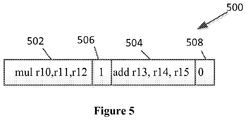
- Figure 5 shows an example 500 of two independent instructions 502, 504, each of the instructions 502, 504 having a corresponding bit 506, 508, reserved for chaining information.
- the chaining bit 506 of the multiply instruction 502 is set to 1 because the add instruction 504 is independent and may be executed in parallel. Any number of bits may be chained together based on the capabilities of a particular processor.
- dependencies may be encoded across a sequence of instructions.
- a 3-issue machine may employ three chaining bits (one from each instruction) to encode 8 possible dependency types.
- chaining may be extended to groups of instructions. For example, "000" decoded from the chaining bits of three instructions may be interpreted as all of the instructions within a current group are not chained and the next group of instructions may not be chained with the current group of instructions.
- one of the chaining bits may be reserved for inter-group parallelism to indicate whether a next group of instructions after a current group of instruction contains any control or data dependencies with the current group of instructions. If there are no dependencies, the next group of instructions may be issued down the pipeline concurrently with the current group of instructions without any pipeline stalls.
- the other chaining bits within an instruction group may describe intra-group parallelism information that indicates parallelism and dependencies between the instructions in the current instruction group.
- Chaining bits may also encode performance improvement techniques, such as informing a processor to use a bypass value rather than reading it again from a register file. In some situations, this may reduce the power dissipated by the processor.
- both parallelism and dependencies may be encoded across a group of instructions.
- Chaining bits may be employed to encode inter-instruction dependencies, inter-group dependencies, and performance optimizations that during execution help to quickly generate the necessary pipeline control signals in a pipelined-processor, thereby eliminating the need for complex dependency checking hardware.
- Figure 6 shows one example of a hardware thread unit within a multithreaded computer processor 600 for decoding chained instructions in which examples of the present disclosure may operate.
- the multithreaded processor 600 may comprise a plurality of hardware thread units 602a-602n.
- Each of the hardware thread units 602a-602n may comprise a program counter (PC) 603, an instruction memory 604, an instruction decoder 606 (labeled "control"), a register file 608, one or more pipeline execution units comprising arithmetic logic units (ALUs) 610a-610n, and a data memory 612.
- PC program counter
- ALUs arithmetic logic units
- "groups" of instructions may be read and decoded from an instruction memory 604 and the decoded information may be employed to generate control signals exiting a control block 606 that control the operations of data path and pipelines.
- Direct register references may be transmitted to a register file 608 (labeled registers 608) and data contained within the register file 608 may be transmitted to one or more arithmetic logic units (ALU) 610a-610n (which, in an example, may comprise instruction pipelines and execution units (not shown)).
- ALU arithmetic logic units
- the results of an operation, stored in the data memory 612, may be written back to the register file 608.
- the program counter (PC) 603 may be updated and the next instruction may be fetched from the instruction memory 604.
- a full description of the computer processor 600 may be found at "www.cise.ufl.edu/ ⁇ mssz/CompOrg/CDA-proc.html,".
- one or more of the elements 603-612 of the multithreaded processor 600 may be shared across hardware thread units 602a-602n.
- one or more of the element 603-612 e.g., the one or more arithmetic logic units (ALUs) 610, the instruction memory (I-Cache) 604, the data memory 612, etc.
- ALUs arithmetic logic units
- I-Cache instruction memory
- data memory 612 etc.
- any of the elements 603-612 that represents processor state need to be replicated for each of the hardware thread units 6Q2a-602n.
- Figure 7 shows one example of an apparatus 700 to extract chaining bits 702 from instructions 704a-704n in an instruction group 706, decode the extracted chaining bits 702, and generate pipeline control signals in which examples of the present disclosure may operate.
- the apparatus 700 may be implemented in a pipeline stage as the other control signals that are shown as the control block 606 in Figure 6 .
- the apparatus 700 may be implemented earlier in the pipeline stage to simplify decoding of information.
- a chaining bit decoder 708 may be configured to decode the semantics of the encoded chaining bit combinations received from the extracted chaining bits 702 and may be configured to generate appropriate controls for the instruction issue controller 710.
- the instruction issue controller 710 may control the issuing of instructions within an instruction group (serial, parallel, or partially parallel) using the control signals 714 or the instruction issue controller 710 may control the issuing of the next instruction group using the control signals 716.
- the instruction issue controller 710 may be configured to receive the commands from the chaining bit decoder 708 and may generate the pipeline control signals to stall instruction issue in pipeline stages 718a-718n (comprising, for example, pipeline clocks 724a-724n, pipeline stage logic 726a-726n, and corresponding registers 728a-728n), if necessary.
- the pipeline status monitor 720 may be configured to monitor instructions currently executing in the pipeline stage 718 and provide feedback 722 to the instruction issue controller 710 to restart instruction issue after a stall.
- Figure 8 is a flow diagram illustrating an example of a method 800 for enabling dependency information, parallelism information, and performance optimizations to be decoded without examining the underlying instructions encoded in a sequence of instructions.
- the method 800 may be performed by the computer processor 600 of Figure 6 and, in one example, may comprise the apparatus 700 (e.g., circuitry, dedicated logic, programmable logic, microcode, etc.) of Figure 7 .
- the chaining bit decoder 700 of the computer processor 600 receives an instruction stream.
- the chaining bit decoder 708 of the apparatus 700 selects a group of instructions from the instruction stream (e.g., the instructions 704a-704n in an instruction group 706).
- the chaining bit decoder 708 extracts a designated bit 702 from each instruction (e.g., 704a-704n) of the instruction stream 704a-704n to produce a sequence of chaining bits 702.
- the chaining bit decoder 708 decodes the sequence of chaining bits 702.
- the chaining bit decoder 708 identifies zero or more dependencies between two or more instructions among the selected group of instructions (e.g., the instructions 704a-704n in an instruction group 706) in view of the decoded sequence of chaining bits 702.
- an identified dependency between two or more instructions among the selected group of instructions 704a-704n may be a control dependency or a data dependency.
- the chaining bit decoder 708 outputs control signals to cause the one or more pipelines stages 718 to execute the selected group of instructions (e.g., the instructions 704a-704n in an instruction group 706) in view of the identified zero or more dependencies between two or more instructions among the selected group of instructions (e.g., the instructions 704a-704n in an instruction group 706).
- the sequence of chaining bits 702 may be decoded by the chaining bit decoder 708 without decoding any of the instructions in the selected group of instructions (e.g., the instructions 704a-704n in an instruction group 706).
- the remaining bits in the decoded sequence of chaining bits 702 may indicate to the instruction issue controller 710 that two or more instructions in the selected group of instructions 704a-704n may be executed in parallel by the pipelines stages 718. In another example, the remaining bits in the decoded sequence of chaining bits 702 may indicate to the instruction issue controller 710 that two or more instructions in the selected group of instructions 704a-704n may be executed in series by the pipelines stages 718. In another example, the remaining bits in the decode sequence of chaining bits 702 may indicate to the instruction issue controller 710 that two or more instructions in the selected group of instructions 704a-704n must be executed in parallel by the pipelines stages 718. In another example, the remaining bits in the decoded sequence of chaining bits 702 may indicate to the instruction issue controller 710 that the selected group of instructions may be executed partially in parallel and partially in series by the pipelines stages 718.
- the number of instructions to place in the selected group of instructions 704a-704n may be based on an issue width of the processor 600.
- the chaining bit decoder 708 may be configured to identify intra-group dependencies within the selected group of instruction using the chaining bits 702. Accordingly, at block 835, the chaining bit decoder 708 may divide the selected group of instructions 704a-704n and associated chaining bits 702 into a first group of instructions and a second group of instruction in order to identify intra-group dependencies (e.g., between groups).
- the chaining bit decoder 708 may identify zero or more dependencies between an instruction of the first group of instructions and an instruction of a second group of instructions selected from the instruction stream based on the decoded sequence of chaining bits 702.
- the chaining bit decoder 708 may output control signals to cause the one or more pipelines stages 718 to execute the second group of instructions based on the identified zero or more dependencies between the instruction of the first group of instructions and the instruction of a second group of instructions.
- a bit in the decoded sequence of chaining bits 702 may indicate that the first group of instructions may be executed in parallel with the second group of instructions.
- An identified dependency between one or more instructions of the first group of instructions and one or more instructions of the second group of instructions may be control dependencies or data dependencies.
- one or more bits in a decoded sequence of chaining bits 702 may be operable to optimize performance of the processor 600.
- the decoded sequence of chaining bits 702 may be operable to function as pipeline control signals for the pipelines stages 718.
- the simplest case of chaining is a single-issue pipelined processor that can issue one instruction per clock cycle if there are no inter-instruction dependencies. As shown in Figure 2 for a typical pipelined-processor, if inter-instruction dependencies exist, the pipeline must stall until the dependencies are resolved. If the chaining bit is set to "1", this is an indication that the next instruction has no control or data dependencies with any instructions within the current instruction chain. Hence, the instruction may be issued immediately. If the chaining bit is set to "0", this is an indication that the next instruction has control and/or data dependencies with at least one instruction within the current instruction chain. Hence, the execution of this instruction cannot commence until all instructions in the current chain complete execution and exit the pipeline.
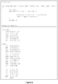
- Figure 9 shows an example of pre-optimized code used to demonstrate chaining in a typical single-issue pipelined processor.
- Figure 9 shows both in C language and assembly language for implementing an example loop that multiplies two source arrays (pointers in registers src1, src2 ) of size NUM and that stores the result into a destination array (pointer in register dst ). The code also accumulates the multiplied result in memory location mac.
- the code reserves space on the stack (pointed to by stack pointer register r1 ) using the store-update instruction ( stwu ), saves the values of the scratch registers, loads the initial value of mac, and clears the value in the count register cnt.
- the code loads the source values that need to be multiplied and accumulated, performs the multiply accumulate, and saves the result from the multiply and accumulate operations.
- the cmp instruction sets fig to 0 if the comparison values are equal or to 1 if the comparison is NOT equal.
- the jc instruction jumps back into the loop if flg is equal to 1.
- the code restores the original values into the scratch registers from the stack, releases the reserved space on the stack, and exits the procedure unconditionally using the j instruction.
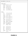
- Figure 10 shows an example of optimized assembly language code that re-orders instructions within the loop of Figure 9 by moving all the independent instructions as early as possible in the code.
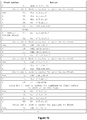
- Figure 11 shows the code of Figure 10 with chaining bits configured according to the semantics of a single-issue pipelined processor discussed above in Figures 6 and 7 .
- the chaining bit for instruction 1 is set to 0 because the second instruction is dependent on the value of register r1 generated by the first instruction.
- the chaining bit for instruction 2 is set to 1 because instruction 3 has no dependencies with instructions in the current instruction chain and can be executed in parallel.
- the chaining bit for instruction 8 is set to 0 because the next instruction ( instruction 9 ) has a read-after-write dependency with instruction 6 which is in the current instruction chain.
- Figure 12 shows an execution snapshot for the single-issue processor of Figures 6 and 7 using instruction chaining for the instruction stream in Figure 11 .
- One instruction may be issued every clock cycle unless a dependency is detected from the chaining bits (chaining bit is 0). Whenever the chaining bit is 0, the next instruction is not issued and the instruction issue pipeline is stalled for n x cycles until all executing instructions complete. This eliminates the need for interlock hardware in the processor pipeline. Once the executing instructions from the current instruction chain complete, the stalled instruction from a new instruction chain may be issued.
- stall cycles are added to the stalled instruction's clock cycle count to indicate the number of cycles that the instruction was waiting to be issued. For example, instruction 1 is issued in one clock cycle. Since the chaining bit of instruction 1 is 0, instruction 2 cannot be issued in the next clock cycle. The pipeline is stalled for n 1 clock cycles until instruction 1 completes execution. Instruction 2 is issued one clock cycle after the stall and hence instruction 2 has been issued after 1 + n 1 . A branch instruction such as jc in instruction 18 will cause the pipeline to flush. Hence the instruction following the branch irrespective of whether the branch is taken ( instruction 7) or not (instruction 19) will have to wait for n 5 clock cycles before it can be issued. While entering the loop for the first time, issue of instruction 7 only takes one clock cycle, whereas during re-entry, it takes 1 + n 5 clock cycles.
- a dual-issue pipelined processor may be configured to issue two instructions (an instruction group) every cycle if there are no instruction dependencies. If there is a dependency between instruction groups, the pipeline is stalled until the dependency is resolved. If there is a dependency within the instruction group, then the instructions within the instruction group are issued serially, i.e., the first instruction is issued and the second instruction is stalled until the first instruction completes execution and exits the pipeline.
- Each instruction in the instruction group has a chaining bit.
- one chaining bit may be used to indicate vertical parallelism (inter-group parallelism) and the second chaining bit may be used to indicate horizontal parallelism (intra-group parallelism).
- Chaining bits i1 and i2 may be taken from the first and second instructions in the instruction group, respectively.
- Chaining bit i1 is the intra-group parallelism bit. If the intra-group parallelism bit is 1, then the second instruction in the group can be issued in parallel with the first instruction in the group. If the intra-group parallelism bit is 0, then the second instruction has to wait until the first instruction has completed execution.
- Chaining bit i2 is the inter-group parallelism bit. If the inter-group parallelism bit is 1, then the next execution group can enter the pipeline in the next clock cycle behind the current executing group. If the inter-group parallelism bit is 0, then the next execution group has to wait until the current execution group has completed execution.
- Figure 14 shows one example of instruction chaining for a dual-issue pipelined processor.
- Figure 14 uses the example code shown in Figure 9 to indicate a possible instruction chain configuration for a dual-issue pipelined processor.
- Figure 15 shows one example of an execution snapshot for the dual-issue instruction stream in Figure 14 .
- Two instructions may be issued every clock cycle if the chaining bits indicate no dependencies.
- the intra-group parallelism bit is set to 0 to indicate a dependency within instructions in the group. This causes instruction 1 to be issued and stalls instruction 2 until instruction 1 completes execution in n 1 cycles.
- the second instruction group has the intra-group parallelism bit set to 1 and hence instruction 3 and instruction 4 are issued together.
- the inter-group parallelism bit for the second instruction group is also set to 1 and hence the third instruction group is issued down the pipeline without any pipeline stalls.
- the inter-group parallelism bit for the fourth instruction group is set to 0, thereby stalling the instruction issue for the fifth group until all instructions in the current chain finish execution. Re-entry into the loop at instruction 7 causes a different number of stall cycles because the branch instruction at the end of the loop ( instruction 18 ) may cause the pipeline to flush all executing instructions.
- a 3-issue pipelined processor may issue three instructions (an instruction group) every cycle if there are no instruction dependencies. If there is a dependency between instruction groups, the pipeline is stalled until the dependency is resolved. If there is a dependency within the instruction group, then the instructions within the instruction group are issued serially or partially parallel as indicated by the chaining bits. Each instruction in the instruction group has a single chaining bit. Hence, in a 3-issue processor, there are three chaining bits available per instruction group yielding 8 semantic combinations. One chaining bit may be used to indicate vertical parallelism (across instruction groups) and the other two chaining bits may be used to indicate horizontal parallelism (within the instruction group).
- Figure 16 shows one example of semantics for instruction chaining in a 3-issue processor.
- the example of semantics for instruction chaining for the chaining bit combinations indicated in Figure 16 offers the maximum flexibility in horizontal parallelism.
- a value of x in figure 16 indicates the chaining bit can be a 0 or a 1.
- Chaining bits i1, i2 and i3 may be taken from the first, second and third instructions in the instruction group, respectively. Chaining bits i1 and i2 are the intra-group parallelism bis t. If i1 or i2 is 1, then the next instruction in the group can be issued in parallel with the current instruction in the group. If i1 or i2 is 0, then the next instruction has to wait until the currently executing instructions have completed execution.
- Chaining bit i3 is inter-group parallelism bit. If i3 is 1, then the next execution group can enter the pipeline in the next clock cycle behind the current execution group. If i3 is 0, then the next execution group needs to wait until the current execution group has completed execution.
- two chaining bits may be sufficient to encode vertical and horizontal parallelism (all three instructions issued together or not).
- the third chaining bit may be used to encode additional information.
- Figure 17 shows one example of an instruction chain configured for a 3-issue pipelined processor for the example code shown in Figure 9 .
- Figure 18 shows an example of an execution snapshot for the 3-issue instruction stream in Figure 17 .
- the execution follows the semantics of the 3 chaining bits within the instruction group as described in Figure 16 .
- the instruction issue across instruction groups is stalled if the inter-group parallelism bit ( i3 ) is set to 0 as is the case between instruction 12 and instruction 13.
- the instructions within the group are also issued in a fully parallel, partially parallel or fully sequential manner based on the intra-group parallelism bits ( i1 , i2 ).
- a 4-issue pipelined processor issues four instructions every cycle if there are no instruction dependencies. If there is a dependency between instruction groups, the pipeline may be stalled until the dependency is resolved. If there is a dependency within the instruction group, then the instructions within the instruction group may be issued serially or partially parallel as indicated by the chaining bits.
- Each instruction in the instruction group has a single chaining bit.
- One chaining bit may be used to indicate vertical parallelism (across instruction groups) and the other three chaining bits may be used to indicate other possibilities for horizontal execution (executing instructions within instruction group).
- Figure 19 shows one example of a set of instruction chaining semantics for a 4-issue processor.
- a value of x in figure 19 indicates the chaining bit can be a 0 or a 1.
- Chaining bits i1, i2, i3, i4 may be taken from the first, second, third and fourth instructions in the instruction group, respectively.
- Chaining bit i4 is an inter-group parallelism bit. If i4 is 1, then the next execution group can enter the pipeline in the next clock cycle behind the current execution group. If i4 is 0, then the next execution group has to wait until the current execution group has completed execution.
- Chaining bits i1, i2, and i3 may be used to indicate intra-group parallelism.
- some combinations of chaining bits i1, i2, and i3 indicate possible parallelism within the instructions in the group (001x, 010x, 011x, 100x) and other combinations indicate mandatory parallelism within instructions in the group (101x, 110x, 111x).
- Possible parallelism exposes the available parallelism, but the processor may or may not use it. The results remain the same whether the instructions are executed in parallel or sequentially.
- Mandatory parallelism indicates that the instructions must be executed in parallel to obtain desired results.
- Figure 20 shows an example of pre-optimized code for a 4-issue processor that illustrates the need for mandatory parallelism.
- Figure 20 shows in C language and assembly language an example loop that swaps the even and odd elements of an array (pointer in register src ) of size NUM.
- the C code uses a variable tmp_swap to accomplish the swapping.
- tmp_swap When converted to assembly, tmp_swap would become a temporary register used for swapping.
- the assembly code can leverage a multiple-issue pipelined architecture to eliminate the temporary register. If two instructions are issued in parallel, they both read the contents of their source registers at the register-read stage in a pipeline and write back the results at the write-back stage later in the pipeline. Hence, a swap operation can be accomplished without a temporary register by issuing two move instructions in parallel, which both read the contents of their source registers together and then write back the swapped values together at a later stage in the pipeline. However, this will only work if the two instructions are executed in parallel. The results will be incorrect if executed sequentially.
- the code reserves space on the stack (pointed to by stack pointer register r1 ), saves the values of the scratch registers, and clears the value in the count register cnt.
- the code loads the source values that need to be swapped, performs the swap operation, and saves the result back into the source array. Note that the two mov operations within the loop directly swap the contents of registers 12 and 13 only if they are executed in parallel.
- the cmp instruction sets flg to 0 if the comparison values are equal or to 1 if the comparison is NOT equal.
- the jc instruction jumps back into the loop if fig is equal to 1.
- the code restores the original values into the scratch registers from the stack, releases the reserved space on the stack, and exits the procedure unconditionally using the j instruction.
- Figure 21 shows one example of re-ordered optimized code for a 4-issue processor.
- Figure 21 shows a re-ordering of instructions within the loop has been performed by moving independent instructions to desired locations.
- Figure 22 shows one example of an instruction chain configured for a 4-issue pipelined processor for the example code shown in Figure 21 .
- the chaining bit i4 indicates inter-group parallelism.
- the first instruction group have chaining bit i4 set to 0, which indicates that the second instruction group needs to wait until the first instruction group has completed execution before the second instruction group can be issued.
- the third instruction group has chaining bit i4 set to 1, which indicates that the fourth instruction group can be issued in parallel with instruction group 3.
- the loop begins at instruction, which is the fourth instruction in the first group. This indicates that jumping into the middle of an instruction group is permitted.
- the chaining bit combination for the second instruction group is 1,1,0,0.
- the chaining bits i1, i2 and i3 are set to 1,1,0, whose semantics as those of Figure 19 in that instructions 1, 2, 3 in the instruction group must be issued in parallel. This ensures that the swap operation performed by instruction 6 and instruction 7 is accomplished correctly.
- the last instruction group has been padded with nop instructions after the exit instruction for completeness.
- Figure 23 shows one example of an execution snapshot for the 4-issue instruction stream in Figure 22 .
- the execution follows the semantics of the 4 chaining bits within the instruction group as described in Figure 19 .
- the instruction issue across instruction groups is stalled if the inter-group parallelism bit ( i4 ) is set to 0.
- the instructions within the group are executed as dictated by chaining bits i1, i2, and i3. Instructions 6 and 7 are executed in parallel to get the desired swap results.
- a programmer may identify the dependencies between groups of instructions in a computer program. The computer programmer may then employ programming techniques to permit a compiler to encode the identified dependencies into executable code using chaining bits that may be employed in the computer processor of Figures 6 and 7 . In another example, the programmer may not identify the aforementioned dependencies directly, but compile a program to be executed by the computer processor of Figures 6 and 7 , in which the compiler identifies the dependencies and compiles executable code using chaining bits.
- Figure 24 is a flow diagram illustrating an example of a method 2400 for enabling dependency information, parallelism information, and performance optimizations to be encoded in a sequence of instructions using a compiler.
- the method 2400 may be performed, for example, by the computer processor of Figures 6 and 7 , by the computer processor described in Figure 25 below, or by other types of computer processors and may comprise hardware (e.g., circuitry, dedicated logic, programmable logic, microcode, etc.), software (e.g., instructions run on a processing device), or a combination thereof.
- the method 2400 may be performed by a compiler 2550 of the computer processor of Figure 25 .
- the compiler 2550 executing on a processor 2502, receives an instruction stream.
- the compiler 2550 selects a group of instructions from the instruction stream.
- the compiler 2550 identifies zero or more instruction stream dependencies among the selected group of instructions.
- the compiler 2550 encodes a bit in each instruction with the zero or more dependencies among the selected group of instructions to produce an encoded sequence of chaining bits.
- the encoded sequence of chaining bits may indicate that two or more instructions in the selected group of instructions may be executed in parallel. In another example, the encoded sequence of chaining bits may indicate that two or more instructions in the selected group of instructions must be executed in series. In another example, the encoded sequence of chaining bits may indicate that two or more instructions in the selected group of instructions must be executed in parallel. In another example, the encoded sequence of chaining bits may indicate that the selected group of instructions may be executed partially in parallel and partially in series.
- the number of instructions for the compiler to place in the selected group of instructions may be based on the issue width of the processor on which the selected group of instructions are to be executed (e.g., the processor 600).
- the compiler may identify a dependency between two or more instructions within the selected group of instructions as a control dependency or a data dependency.
- one or more bits in the encoded sequence of chaining bits may be operable to optimize performance of the executable program.
- the encoded sequence of chaining bits may be operable to function as pipeline control signals.
- the compiler 2550 may divide the selected group of instructions into a first group of instructions and a second group of instructions.
- the compiler 2550 may identify zero or more instruction stream dependencies between the first group of instructions and the second group of instructions.
- the compiler 2550 may further encode the encoded sequence of chaining bits with the zero or more instruction stream dependencies between the first group of instructions and the second group of instructions. In an example, a bit in the encoded sequence of chaining bits may indicate that the first group of instructions may be executed in parallel with the second group of instructions.
- Figure 25 illustrates a diagrammatic representation of a machine in the example form of a computer system 2500 within which a set of instructions, for causing the machine to perform any one or more of the methodologies discussed herein, may be executed.
- the machine may be connected (e.g., networked) to other machines in a LAN, an intranet, an extranet, or the Internet.
- the machine may operate in the capacity of a server machine in client-server network environment.
- the machine may be a personal computer (PC), a set-top box (STB), a server, a network router, switch or bridge, or any machine capable of executing a set of instructions (sequential or otherwise) that specify actions to be taken by that machine.
- PC personal computer
- STB set-top box
- STB set-top box
- server a server
- network router switch or bridge
- the example computer system 2500 includes a processing device (processor) 2502, a main memory 2504 (e.g., read-only memory (ROM), flash memory, dynamic random access memory (DRAM) such as synchronous DRAM (SDRAM)), a static memory 2506 (e.g., flash memory, static random access memory (SRAM)), and a data storage device 2516, which communicate with each other via a bus 2508.
- processor processing device
- main memory 2504 e.g., read-only memory (ROM), flash memory, dynamic random access memory (DRAM) such as synchronous DRAM (SDRAM)
- DRAM dynamic random access memory
- SDRAM synchronous DRAM
- static memory 2506 e.g., flash memory, static random access memory (SRAM)
- SRAM static random access memory
- Processor 2502 represents one or more general-purpose processing devices such as a microprocessor, central processing unit, or the like. More particularly, the processor 2502 may be a complex instruction set computing (CISC) microprocessor, reduced instruction set computing (RISC) microprocessor, very long instruction word (VLIW) microprocessor, or a processor implementing other instruction sets or processors implementing a combination of instruction sets.
- the processor 2502 may also be one or more special-purpose processing devices such as an application specific integrated circuit (ASIC), a field programmable gate array (FPGA), a digital signal processor (DSP), network processor, or the like.
- the compiler 2550 may be executed by processor 2502 configured to perform the operations and steps discussed herein.
- the computer system 2500 may further include a network interface device 2522.
- the computer system 2500 also may include a video display unit 2510 (e.g., a liquid crystal display (LCD) or a cathode ray tube (CRT)), an alphanumeric input device 2512 (e.g., a keyboard), a cursor control device 2514 (e.g., a mouse), and a signal generation device 2520 (e.g., a speaker).
- a video display unit 2510 e.g., a liquid crystal display (LCD) or a cathode ray tube (CRT)
- an alphanumeric input device 2512 e.g., a keyboard
- a cursor control device 2514 e.g., a mouse
- a signal generation device 2520 e.g., a speaker
- a drive unit 2516 may include a computer-readable medium 2524 on which is stored one or more sets of instructions (e.g., instructions to be compiled by the compiler 2550) embodying any one or more of the methodologies or functions described herein.
- the instructions to be compiled by the compiler 2550 may also reside, completely or at least partially, within the main memory 2504 and/or within the processor 2502 during execution thereof by the computer system 2500, the main memory 2504 and the processor 2502 also constituting computer-readable media.
- the instructions to be compiled by the compiler 2550 may further be transmitted or received over a network 2526 via the network interface device 722.
- While the computer-readable storage medium 2524 is shown in an example to be a single medium, the term “computer-readable storage medium” should be taken to include a single non-transitory medium or multiple non-transitory media (e.g., a centralized or distributed database, and/or associated caches and servers) that store the one or more sets of instructions.
- the term “computer-readable storage medium” shall also be taken to include any medium that is capable of storing, encoding or carrying a set of instructions for execution by the machine and that cause the machine to perform any one or more of the methodologies of the present disclosure.
- the term “computer-readable storage medium” shall accordingly be taken to include, but not be limited to, solid-state memories, optical media, and magnetic media.
- Examples of the disclosure also relate to an apparatus for performing the operations herein.
- This apparatus may be specially constructed for the required purposes, or it may comprise a general purpose computer selectively activated or reconfigured by a computer program stored in the computer.
- a computer program may be stored in a computer readable storage medium, such as, but not limited to, any type of disk including floppy disks, optical disks, CD-ROMs, and magnetic-optical disks, read-only memories (ROMs), random access memories (RAMs), EPROMs, EEPROMs, magnetic or optical cards, or any type of media suitable for storing electronic instructions.
Landscapes
- Engineering & Computer Science (AREA)
- Software Systems (AREA)
- Theoretical Computer Science (AREA)
- Physics & Mathematics (AREA)
- General Engineering & Computer Science (AREA)
- General Physics & Mathematics (AREA)
- Advance Control (AREA)
- Devices For Executing Special Programs (AREA)
Claims (15)
- Procédé servant à traiter des instructions en mesure d'être exécutées par un processeur, comportant les étapes consistant à :sélectionner, par un processeur, un groupe d'instructions en provenance d'un flux d'instructions ;extraire, par le processeur, un bit de chaînage respectif en provenance de chaque instruction dans le groupe d'instructions ayant été sélectionné ;réassembler, par le processeur, les bits de chaînage ayant été extraits pour former une combinaison de bits de chaînage, dans lequel la combinaison de bits de chaînage a pour objet de représenter une pluralité de types d'émission d'instructions pour le groupe d'instructions ayant été sélectionné, et dans lequel la pluralité de types d'émission d'instructions comporte une exécution parallèle de type intra-groupe et une exécution parallèle de type inter-groupe ;décoder, par le processeur, la combinaison de bits de chaînage pour déterminer un premier type d'émission d'instructions de la pluralité de types d'émission d'instructions ;identifier, par le processeur en fonction du premier type d'émission d'instructions, zéro ou plusieurs dépendances du flux d'instructions parmi le groupe d'instructions ayant été sélectionné sans décoder entièrement l'une quelconque du groupe d'instructions ayant été sélectionné ; etémettre en sortie, par le processeur, des signaux de commande pour commander l'exécution du groupe d'instructions ayant été sélectionné au niveau d'un ou de plusieurs étages en pipeline du processeur en fonction desdites zéro ou plusieurs dépendances du flux d'instructions ayant été identifiées.
- Procédé selon la revendication 1, dans lequel la combinaison de bits de chaînage comporte un premier bit correspondant à l'exécution parallèle de type intra-groupe et un deuxième bit correspondant à l'exécution parallèle de type inter-groupe.
- Procédé selon la revendication 1 ou la revendication 2, comportant par ailleurs les étapes consistant à :diviser le groupe d'instructions ayant été sélectionné en un premier groupe d'instructions et un deuxième groupe d'instructions ;identifier, par le processeur, zéro ou plusieurs dépendances du flux d'instructions entre le premier groupe d'instructions et le deuxième groupe d'instructions en fonction de la combinaison de bits de chaînage ayant été décodée ; etémettre en sortie, par le processeur, les signaux de commande pour amener lesdits un ou plusieurs étages en pipeline à exécuter le deuxième groupe d'instructions en fonction desdites zéro ou plusieurs dépendances du flux d'instructions ayant été identifiées entre le premier groupe d'instructions et le deuxième groupe d'instructions.
- Procédé selon la revendication 3, dans lequel un bit dans la combinaison de bits de chaînage ayant été décodée indique que le premier groupe d'instructions doit être exécuté en parallèle par rapport au deuxième groupe d'instructions.
- Procédé selon l'une quelconque des revendications 1 à 4, dans lequel la combinaison de bits de chaînage ayant été décodée indique que deux ou plusieurs instructions dans le groupe d'instructions ayant été sélectionné doivent être exécutées soit en parallèle soit en série.
- Procédé selon l'une quelconque des revendications 1 à 4, dans lequel la combinaison de bits de chaînage ayant été décodée indique que les instructions du groupe d'instructions ayant été sélectionné doivent être exécutées partiellement en parallèle et partiellement en série.
- Procédé selon l'une quelconque des revendications 1 à 6, dans lequel un nombre d'instructions dans le groupe d'instructions ayant été sélectionné est sélectionné en fonction d'une largeur d'émission du processeur.
- Procédé selon l'une quelconque des revendications 1 à 7, dans lequel une dépendance du flux d'instructions ayant été identifiée parmi deux ou plusieurs instructions dans les limites du groupe d'instructions ayant été sélectionné est une dépendance de commande ou une dépendance de données.
- Procédé selon la revendication 3, dans lequel une dépendance du flux d'instructions ayant été identifiée entre une ou plusieurs instructions du premier groupe d'instructions et une ou plusieurs instructions du deuxième groupe d'instructions est une dépendance de commande ou une dépendance de données.
- Procédé selon l'une quelconque des revendications 1 à 9, dans lequel un ou plusieurs bits dans la combinaison de bits de chaînage ayant été décodée servent à optimiser la performance du processeur.
- Procédé selon l'une quelconque des revendications 1 à 10, dans lequel la combinaison de bits de chaînage ayant été décodée sert à tenir lieu de signaux de commande en pipeline.
- Système servant à traiter des instructions en mesure d'être exécutées par un processeur, comportant :une mémoire ; etun processeur, couplé à la mémoire, le processeur comportant un décodeur de bits de chaînage ayant accès à la mémoire, le décodeur de bits de chaînage servant à :sélectionner un groupe d'instructions en provenance d'un flux d'instructions ;extraire un bit de chaînage respectif en provenance de chaque instruction dans le groupe d'instructions ayant été sélectionné ;réassembler les bits de chaînage ayant été extraits pour former une combinaison de bits de chaînage, dans lequel la combinaison de bits de chaînage a pour objet de représenter une pluralité de types d'émission d'instructions pour le groupe d'instructions ayant été sélectionné, et dans lequel la pluralité de types d'émission d'instructions comporte une exécution parallèle de type intra-groupe et une exécution parallèle de type inter-groupe ;décoder la combinaison de bits de chaînage pour déterminer un premier type d'émission d'instructions de la pluralité de types d'émission d'instructions ;identifier, en fonction du premier type d'émission d'instructions, zéro ou plusieurs dépendances du flux d'instructions parmi le groupe d'instructions ayant été sélectionné sans décoder entièrement l'une quelconque du groupe d'instructions ayant été sélectionné ; etémettre en sortie des signaux de commande pour commander l'exécution du groupe d'instructions ayant été sélectionné au niveau d'un ou de plusieurs étages en pipeline du processeur en fonction desdites zéro ou plusieurs dépendances du flux d'instructions ayant été identifiées.
- Système selon la revendication 12, dans lequel le décodeur de bits de chaînage sert par ailleurs à :diviser le groupe d'instructions ayant été sélectionné en un premier groupe d'instructions et un deuxième groupe d'instructions ;identifier zéro ou plusieurs dépendances du flux d'instructions entre le premier groupe d'instructions et le deuxième groupe d'instructions en fonction de la combinaison de bits de chaînage ayant été décodée ; etémettre en sortie les signaux de commande pour amener lesdits un ou plusieurs étages en pipeline à exécuter le deuxième groupe d'instructions en fonction desdites zéro ou plusieurs dépendances du flux d'instructions ayant été identifiées entre le premier groupe d'instructions et le deuxième groupe d'instructions.
- Support lisible par machine ayant, stocké sur celui-ci, un code qui, quand il est exécuté, amène le processeur selon la revendication 12 à :sélectionner, par le processeur, un groupe d'instructions en provenance du flux d'instructions ;extraire, par le processeur, un bit de chaînage respectif en provenance de chaque instruction dans le groupe d'instructions ayant été sélectionné ;réassembler, par le processeur, les bits de chaînage ayant été extraits pour former une combinaison de bits de chaînage, dans lequel la combinaison de bits de chaînage a pour objet de représenter une pluralité de types d'émission d'instructions pour le groupe d'instructions ayant été sélectionné, et dans lequel la pluralité de types d'émission d'instructions comporte une exécution parallèle de type intra-groupe et une exécution parallèle de type inter-groupe ;décoder, par le processeur, la combinaison de bits de chaînage pour déterminer un premier type d'émission d'instructions de la pluralité de types d'émission d'instructions ;identifier, par le processeur en fonction du premier type d'émission d'instructions, zéro ou plusieurs dépendances du flux d'instructions parmi le groupe d'instructions ayant été sélectionné sans décoder entièrement l'une quelconque du groupe d'instructions ayant été sélectionné ; etémettre en sortie, par le processeur, des signaux de commande pour commander l'exécution du groupe d'instructions ayant été sélectionné au niveau d'un ou de plusieurs étages en pipeline du processeur en fonction desdites zéro ou plusieurs dépendances du flux d'instructions ayant été identifiées.
- Support lisible par machine selon la revendication 14, dans lequel la combinaison de bits de chaînage comporte un premier bit correspondant à l'exécution parallèle de type intra-groupe et un deuxième bit correspondant à l'exécution parallèle de type inter-groupe.
Applications Claiming Priority (3)
| Application Number | Priority Date | Filing Date | Title |
|---|---|---|---|
| US201461936428P | 2014-02-06 | 2014-02-06 | |
| US14/539,104 US9766894B2 (en) | 2014-02-06 | 2014-11-12 | Method and apparatus for enabling a processor to generate pipeline control signals |
| PCT/US2015/014064 WO2015119886A1 (fr) | 2014-02-06 | 2015-02-02 | Procédé et appareil permettant à un processeur de générer des signaux de commande en pipeline |
Publications (3)
| Publication Number | Publication Date |
|---|---|
| EP3103302A1 EP3103302A1 (fr) | 2016-12-14 |
| EP3103302A4 EP3103302A4 (fr) | 2018-01-17 |
| EP3103302B1 true EP3103302B1 (fr) | 2019-08-07 |
Family
ID=53754885
Family Applications (1)
| Application Number | Title | Priority Date | Filing Date |
|---|---|---|---|
| EP15746535.2A Active EP3103302B1 (fr) | 2014-02-06 | 2015-02-02 | Procédé et appareil permettant à un processeur de générer des signaux de commande en pipeline |
Country Status (5)
| Country | Link |
|---|---|
| US (1) | US9766894B2 (fr) |
| EP (1) | EP3103302B1 (fr) |
| KR (1) | KR102311619B1 (fr) |
| CN (1) | CN106465404B (fr) |
| WO (1) | WO2015119886A1 (fr) |
Families Citing this family (15)
| Publication number | Priority date | Publication date | Assignee | Title |
|---|---|---|---|---|
| GB2514618B (en) * | 2013-05-31 | 2020-11-11 | Advanced Risc Mach Ltd | Data processing systems |
| US10942747B2 (en) | 2017-11-30 | 2021-03-09 | International Business Machines Corporation | Head and tail pointer manipulation in a first-in-first-out issue queue |
| US10564979B2 (en) | 2017-11-30 | 2020-02-18 | International Business Machines Corporation | Coalescing global completion table entries in an out-of-order processor |
| US10922087B2 (en) | 2017-11-30 | 2021-02-16 | International Business Machines Corporation | Block based allocation and deallocation of issue queue entries |
| US10929140B2 (en) * | 2017-11-30 | 2021-02-23 | International Business Machines Corporation | Scalable dependency matrix with a single summary bit in an out-of-order processor |
| US10572264B2 (en) | 2017-11-30 | 2020-02-25 | International Business Machines Corporation | Completing coalesced global completion table entries in an out-of-order processor |
| US10564976B2 (en) | 2017-11-30 | 2020-02-18 | International Business Machines Corporation | Scalable dependency matrix with multiple summary bits in an out-of-order processor |
| US10884753B2 (en) | 2017-11-30 | 2021-01-05 | International Business Machines Corporation | Issue queue with dynamic shifting between ports |
| US10802829B2 (en) | 2017-11-30 | 2020-10-13 | International Business Machines Corporation | Scalable dependency matrix with wake-up columns for long latency instructions in an out-of-order processor |
| US10901744B2 (en) | 2017-11-30 | 2021-01-26 | International Business Machines Corporation | Buffered instruction dispatching to an issue queue |
| CN110659069B (zh) * | 2018-06-28 | 2022-08-19 | 赛灵思公司 | 用于执行神经网络计算的指令调度方法及相应计算系统 |
| CN111008042B (zh) * | 2019-11-22 | 2022-07-05 | 中国科学院计算技术研究所 | 基于异构流水线的高效通用处理器执行方法及系统 |
| CN113342528A (zh) * | 2021-06-15 | 2021-09-03 | 鹏城实验室 | 指令处理方法及处理器 |
| US20230244475A1 (en) * | 2022-01-28 | 2023-08-03 | International Business Machines Corporation | Automatic extract, transform and load accelerator for data platform in distributed computing environment |
| CN115629807B (zh) * | 2022-10-31 | 2023-04-14 | 海光信息技术股份有限公司 | 多线程处理器的译码方法、处理器、芯片及电子设备 |
Family Cites Families (31)
| Publication number | Priority date | Publication date | Assignee | Title |
|---|---|---|---|---|
| US5303356A (en) | 1990-05-04 | 1994-04-12 | International Business Machines Corporation | System for issuing instructions for parallel execution subsequent to branch into a group of member instructions with compoundability in dictation tag |
| US5463446A (en) * | 1993-05-20 | 1995-10-31 | Canon Kabushiki Kaisha | Rotary member a process cartridge and an assembling method for rolling members |
| US5392393A (en) | 1993-06-04 | 1995-02-21 | Sun Microsystems, Inc. | Architecture for a high performance three dimensional graphics accelerator |
| US6138230A (en) | 1993-10-18 | 2000-10-24 | Via-Cyrix, Inc. | Processor with multiple execution pipelines using pipe stage state information to control independent movement of instructions between pipe stages of an execution pipeline |
| DE69422780T2 (de) * | 1993-11-05 | 2000-08-17 | Intergraph Corp | Superskalare Rechnerarchitektur mit Softwarescheduling |
| US5822559A (en) * | 1996-01-02 | 1998-10-13 | Advanced Micro Devices, Inc. | Apparatus and method for aligning variable byte-length instructions to a plurality of issue positions |
| US6260189B1 (en) | 1998-09-14 | 2001-07-10 | Lucent Technologies Inc. | Compiler-controlled dynamic instruction dispatch in pipelined processors |
| US6192384B1 (en) * | 1998-09-14 | 2001-02-20 | The Board Of Trustees Of The Leland Stanford Junior University | System and method for performing compound vector operations |
| US6668317B1 (en) | 1999-08-31 | 2003-12-23 | Intel Corporation | Microengine for parallel processor architecture |
| US7925869B2 (en) | 1999-12-22 | 2011-04-12 | Ubicom, Inc. | Instruction-level multithreading according to a predetermined fixed schedule in an embedded processor using zero-time context switching |
| US7143268B2 (en) * | 2000-12-29 | 2006-11-28 | Stmicroelectronics, Inc. | Circuit and method for instruction compression and dispersal in wide-issue processors |
| US6907520B2 (en) | 2001-01-11 | 2005-06-14 | Sun Microsystems, Inc. | Threshold-based load address prediction and new thread identification in a multithreaded microprocessor |
| US6928645B2 (en) | 2001-03-30 | 2005-08-09 | Intel Corporation | Software-based speculative pre-computation and multithreading |
| US6842848B2 (en) | 2002-10-11 | 2005-01-11 | Sandbridge Technologies, Inc. | Method and apparatus for token triggered multithreading |
| JP4740851B2 (ja) | 2003-08-28 | 2011-08-03 | ミップス テクノロジーズ インコーポレイテッド | 仮想プロセッサリソースの動的構成のための機構体 |
| US7600221B1 (en) * | 2003-10-06 | 2009-10-06 | Sun Microsystems, Inc. | Methods and apparatus of an architecture supporting execution of instructions in parallel |
| US7310722B2 (en) | 2003-12-18 | 2007-12-18 | Nvidia Corporation | Across-thread out of order instruction dispatch in a multithreaded graphics processor |
| US8074051B2 (en) | 2004-04-07 | 2011-12-06 | Aspen Acquisition Corporation | Multithreaded processor with multiple concurrent pipelines per thread |
| US7543132B1 (en) | 2004-06-30 | 2009-06-02 | Sun Microsystems, Inc. | Optimizing hardware TLB reload performance in a highly-threaded processor with multiple page sizes |
| US7487503B2 (en) | 2004-08-12 | 2009-02-03 | International Business Machines Corporation | Scheduling threads in a multiprocessor computer |
| US20060130062A1 (en) | 2004-12-14 | 2006-06-15 | International Business Machines Corporation | Scheduling threads in a multi-threaded computer |
| US7652922B2 (en) | 2005-09-30 | 2010-01-26 | Mosaid Technologies Incorporated | Multiple independent serial link memory |
| CN1988431B (zh) * | 2005-12-21 | 2010-12-08 | 美国博通公司 | 信号处理的方法及系统 |
| US20070233961A1 (en) * | 2006-03-31 | 2007-10-04 | Banning John P | Multi-portioned instruction memory |
| US8456191B2 (en) | 2006-06-21 | 2013-06-04 | Element Cxi, Llc | Data-driven integrated circuit architecture |
| US20080126766A1 (en) | 2006-11-03 | 2008-05-29 | Saurabh Chheda | Securing microprocessors against information leakage and physical tampering |
| WO2009022294A2 (fr) | 2007-08-14 | 2009-02-19 | Nokia Corporation | Économie d'énergie pour une signalisation et un décodage d'allocation d'ordonnancement de liaison montante |
| US8737517B2 (en) * | 2008-03-26 | 2014-05-27 | Qualcomm Incorporated | Scrambling and modulation to constrain the constellation size of ACK/NAK transmission on the data channel |
| CN102238599A (zh) * | 2010-05-06 | 2011-11-09 | 中兴通讯股份有限公司 | 远端射频单元管理装置、系统及方法 |
| US8499299B1 (en) | 2010-06-29 | 2013-07-30 | Ca, Inc. | Ensuring deterministic thread context switching in virtual machine applications |
| CN102495726B (zh) | 2011-11-15 | 2015-05-20 | 无锡德思普科技有限公司 | 机会多线程方法及处理器 |
-
2014
- 2014-11-12 US US14/539,104 patent/US9766894B2/en active Active
-
2015
- 2015-02-02 KR KR1020167024488A patent/KR102311619B1/ko active IP Right Grant
- 2015-02-02 EP EP15746535.2A patent/EP3103302B1/fr active Active
- 2015-02-02 WO PCT/US2015/014064 patent/WO2015119886A1/fr active Application Filing
- 2015-02-02 CN CN201580012420.4A patent/CN106465404B/zh active Active
Non-Patent Citations (1)
| Title |
|---|
| None * |
Also Published As
| Publication number | Publication date |
|---|---|
| US9766894B2 (en) | 2017-09-19 |
| WO2015119886A1 (fr) | 2015-08-13 |
| CN106465404B (zh) | 2019-11-26 |
| EP3103302A1 (fr) | 2016-12-14 |
| EP3103302A4 (fr) | 2018-01-17 |
| KR102311619B1 (ko) | 2021-10-08 |
| US20150220342A1 (en) | 2015-08-06 |
| KR20160110529A (ko) | 2016-09-21 |
| CN106465404A (zh) | 2017-02-22 |
Similar Documents
| Publication | Publication Date | Title |
|---|---|---|
| EP3103302B1 (fr) | Procédé et appareil permettant à un processeur de générer des signaux de commande en pipeline | |
| CN108027769B (zh) | 使用寄存器访问指令发起指令块执行 | |
| US10871967B2 (en) | Register read/write ordering | |
| EP3103015B1 (fr) | Traitement multifil déterministe et opportuniste | |
| US10409606B2 (en) | Verifying branch targets | |
| KR100464406B1 (ko) | 가변길이 vliw 명령어를 위한 디스패치 장치 및 방법 | |
| CN108027773B (zh) | 存储器访问指令顺序编码的生成和使用 | |
| US9038042B2 (en) | Staged loop instructions | |
| US10095519B2 (en) | Instruction block address register | |
| US20170083341A1 (en) | Segmented instruction block | |
| US11977891B2 (en) | Implicit program order | |
| US20160378491A1 (en) | Determination of target location for transfer of processor control | |
| JP2018519602A (ja) | 連続ブロックの並列実行を有するブロックベースアーキテクチャ | |
| US20170083331A1 (en) | Memory synchronization in block-based processors | |
| US20070083736A1 (en) | Instruction packer for digital signal processor | |
| KR20140131472A (ko) | 상수 저장 레지스터를 구비하는 재구성 가능 프로세서 | |
| US20220035635A1 (en) | Processor with multiple execution pipelines | |
| CN108027735B (zh) | 用于操作处理器的装置、方法和计算机可读存储介质 | |
| WO2017048645A1 (fr) | Cibles multimodales dans un processeur à base de blocs | |
| FitzRoy-Dale | The VLIW and EPIC processor architectures |
Legal Events
| Date | Code | Title | Description |
|---|---|---|---|
| PUAI | Public reference made under article 153(3) epc to a published international application that has entered the european phase |
Free format text: ORIGINAL CODE: 0009012 |
|
| STAA | Information on the status of an ep patent application or granted ep patent |
Free format text: STATUS: REQUEST FOR EXAMINATION WAS MADE |
|
| 17P | Request for examination filed |
Effective date: 20160728 |
|
| AK | Designated contracting states |
Kind code of ref document: A1 Designated state(s): AL AT BE BG CH CY CZ DE DK EE ES FI FR GB GR HR HU IE IS IT LI LT LU LV MC MK MT NL NO PL PT RO RS SE SI SK SM TR |
|
| AX | Request for extension of the european patent |
Extension state: BA ME |
|
| DAX | Request for extension of the european patent (deleted) | ||
| A4 | Supplementary search report drawn up and despatched |
Effective date: 20171219 |
|
| RIC1 | Information provided on ipc code assigned before grant |
Ipc: H04W 72/12 20090101AFI20171213BHEP Ipc: G06F 9/38 20180101ALI20171213BHEP |
|
| STAA | Information on the status of an ep patent application or granted ep patent |
Free format text: STATUS: EXAMINATION IS IN PROGRESS |
|
| 17Q | First examination report despatched |
Effective date: 20180725 |
|
| GRAP | Despatch of communication of intention to grant a patent |
Free format text: ORIGINAL CODE: EPIDOSNIGR1 |
|
| STAA | Information on the status of an ep patent application or granted ep patent |
Free format text: STATUS: GRANT OF PATENT IS INTENDED |
|
| INTG | Intention to grant announced |
Effective date: 20190228 |
|
| GRAS | Grant fee paid |
Free format text: ORIGINAL CODE: EPIDOSNIGR3 |
|
| GRAA | (expected) grant |
Free format text: ORIGINAL CODE: 0009210 |
|
| STAA | Information on the status of an ep patent application or granted ep patent |
Free format text: STATUS: THE PATENT HAS BEEN GRANTED |
|
| RAP1 | Party data changed (applicant data changed or rights of an application transferred) |
Owner name: OPTIMUM SEMICONDUCTOR TECHNOLOGIES INC. |
|
| AK | Designated contracting states |
Kind code of ref document: B1 Designated state(s): AL AT BE BG CH CY CZ DE DK EE ES FI FR GB GR HR HU IE IS IT LI LT LU LV MC MK MT NL NO PL PT RO RS SE SI SK SM TR |
|
| REG | Reference to a national code |
Ref country code: GB Ref legal event code: FG4D |
|
| REG | Reference to a national code |
Ref country code: CH Ref legal event code: EP Ref country code: AT Ref legal event code: REF Ref document number: 1165834 Country of ref document: AT Kind code of ref document: T Effective date: 20190815 |
|
| REG | Reference to a national code |
Ref country code: IE Ref legal event code: FG4D |
|
| REG | Reference to a national code |
Ref country code: DE Ref legal event code: R096 Ref document number: 602015035304 Country of ref document: DE |
|
| REG | Reference to a national code |
Ref country code: NL Ref legal event code: MP Effective date: 20190807 |
|
| REG | Reference to a national code |
Ref country code: LT Ref legal event code: MG4D |
|
| PG25 | Lapsed in a contracting state [announced via postgrant information from national office to epo] |
Ref country code: SE Free format text: LAPSE BECAUSE OF FAILURE TO SUBMIT A TRANSLATION OF THE DESCRIPTION OR TO PAY THE FEE WITHIN THE PRESCRIBED TIME-LIMIT Effective date: 20190807 Ref country code: BG Free format text: LAPSE BECAUSE OF FAILURE TO SUBMIT A TRANSLATION OF THE DESCRIPTION OR TO PAY THE FEE WITHIN THE PRESCRIBED TIME-LIMIT Effective date: 20191107 Ref country code: HR Free format text: LAPSE BECAUSE OF FAILURE TO SUBMIT A TRANSLATION OF THE DESCRIPTION OR TO PAY THE FEE WITHIN THE PRESCRIBED TIME-LIMIT Effective date: 20190807 Ref country code: NL Free format text: LAPSE BECAUSE OF FAILURE TO SUBMIT A TRANSLATION OF THE DESCRIPTION OR TO PAY THE FEE WITHIN THE PRESCRIBED TIME-LIMIT Effective date: 20190807 Ref country code: PT Free format text: LAPSE BECAUSE OF FAILURE TO SUBMIT A TRANSLATION OF THE DESCRIPTION OR TO PAY THE FEE WITHIN THE PRESCRIBED TIME-LIMIT Effective date: 20191209 Ref country code: LT Free format text: LAPSE BECAUSE OF FAILURE TO SUBMIT A TRANSLATION OF THE DESCRIPTION OR TO PAY THE FEE WITHIN THE PRESCRIBED TIME-LIMIT Effective date: 20190807 Ref country code: FI Free format text: LAPSE BECAUSE OF FAILURE TO SUBMIT A TRANSLATION OF THE DESCRIPTION OR TO PAY THE FEE WITHIN THE PRESCRIBED TIME-LIMIT Effective date: 20190807 Ref country code: NO Free format text: LAPSE BECAUSE OF FAILURE TO SUBMIT A TRANSLATION OF THE DESCRIPTION OR TO PAY THE FEE WITHIN THE PRESCRIBED TIME-LIMIT Effective date: 20191107 |
|
| REG | Reference to a national code |
Ref country code: AT Ref legal event code: MK05 Ref document number: 1165834 Country of ref document: AT Kind code of ref document: T Effective date: 20190807 |
|
| PG25 | Lapsed in a contracting state [announced via postgrant information from national office to epo] |
Ref country code: LV Free format text: LAPSE BECAUSE OF FAILURE TO SUBMIT A TRANSLATION OF THE DESCRIPTION OR TO PAY THE FEE WITHIN THE PRESCRIBED TIME-LIMIT Effective date: 20190807 Ref country code: GR Free format text: LAPSE BECAUSE OF FAILURE TO SUBMIT A TRANSLATION OF THE DESCRIPTION OR TO PAY THE FEE WITHIN THE PRESCRIBED TIME-LIMIT Effective date: 20191108 Ref country code: IS Free format text: LAPSE BECAUSE OF FAILURE TO SUBMIT A TRANSLATION OF THE DESCRIPTION OR TO PAY THE FEE WITHIN THE PRESCRIBED TIME-LIMIT Effective date: 20191207 Ref country code: RS Free format text: LAPSE BECAUSE OF FAILURE TO SUBMIT A TRANSLATION OF THE DESCRIPTION OR TO PAY THE FEE WITHIN THE PRESCRIBED TIME-LIMIT Effective date: 20190807 Ref country code: ES Free format text: LAPSE BECAUSE OF FAILURE TO SUBMIT A TRANSLATION OF THE DESCRIPTION OR TO PAY THE FEE WITHIN THE PRESCRIBED TIME-LIMIT Effective date: 20190807 Ref country code: AL Free format text: LAPSE BECAUSE OF FAILURE TO SUBMIT A TRANSLATION OF THE DESCRIPTION OR TO PAY THE FEE WITHIN THE PRESCRIBED TIME-LIMIT Effective date: 20190807 |
|
| PG25 | Lapsed in a contracting state [announced via postgrant information from national office to epo] |
Ref country code: TR Free format text: LAPSE BECAUSE OF FAILURE TO SUBMIT A TRANSLATION OF THE DESCRIPTION OR TO PAY THE FEE WITHIN THE PRESCRIBED TIME-LIMIT Effective date: 20190807 |
|
| PG25 | Lapsed in a contracting state [announced via postgrant information from national office to epo] |
Ref country code: DK Free format text: LAPSE BECAUSE OF FAILURE TO SUBMIT A TRANSLATION OF THE DESCRIPTION OR TO PAY THE FEE WITHIN THE PRESCRIBED TIME-LIMIT Effective date: 20190807 Ref country code: IT Free format text: LAPSE BECAUSE OF FAILURE TO SUBMIT A TRANSLATION OF THE DESCRIPTION OR TO PAY THE FEE WITHIN THE PRESCRIBED TIME-LIMIT Effective date: 20190807 Ref country code: AT Free format text: LAPSE BECAUSE OF FAILURE TO SUBMIT A TRANSLATION OF THE DESCRIPTION OR TO PAY THE FEE WITHIN THE PRESCRIBED TIME-LIMIT Effective date: 20190807 Ref country code: EE Free format text: LAPSE BECAUSE OF FAILURE TO SUBMIT A TRANSLATION OF THE DESCRIPTION OR TO PAY THE FEE WITHIN THE PRESCRIBED TIME-LIMIT Effective date: 20190807 Ref country code: RO Free format text: LAPSE BECAUSE OF FAILURE TO SUBMIT A TRANSLATION OF THE DESCRIPTION OR TO PAY THE FEE WITHIN THE PRESCRIBED TIME-LIMIT Effective date: 20190807 Ref country code: PL Free format text: LAPSE BECAUSE OF FAILURE TO SUBMIT A TRANSLATION OF THE DESCRIPTION OR TO PAY THE FEE WITHIN THE PRESCRIBED TIME-LIMIT Effective date: 20190807 |
|
| PG25 | Lapsed in a contracting state [announced via postgrant information from national office to epo] |
Ref country code: SM Free format text: LAPSE BECAUSE OF FAILURE TO SUBMIT A TRANSLATION OF THE DESCRIPTION OR TO PAY THE FEE WITHIN THE PRESCRIBED TIME-LIMIT Effective date: 20190807 Ref country code: SK Free format text: LAPSE BECAUSE OF FAILURE TO SUBMIT A TRANSLATION OF THE DESCRIPTION OR TO PAY THE FEE WITHIN THE PRESCRIBED TIME-LIMIT Effective date: 20190807 Ref country code: IS Free format text: LAPSE BECAUSE OF FAILURE TO SUBMIT A TRANSLATION OF THE DESCRIPTION OR TO PAY THE FEE WITHIN THE PRESCRIBED TIME-LIMIT Effective date: 20200224 Ref country code: CZ Free format text: LAPSE BECAUSE OF FAILURE TO SUBMIT A TRANSLATION OF THE DESCRIPTION OR TO PAY THE FEE WITHIN THE PRESCRIBED TIME-LIMIT Effective date: 20190807 |
|
| REG | Reference to a national code |
Ref country code: DE Ref legal event code: R097 Ref document number: 602015035304 Country of ref document: DE |
|
| PLBE | No opposition filed within time limit |
Free format text: ORIGINAL CODE: 0009261 |
|
| STAA | Information on the status of an ep patent application or granted ep patent |
Free format text: STATUS: NO OPPOSITION FILED WITHIN TIME LIMIT |
|
| PG2D | Information on lapse in contracting state deleted |
Ref country code: IS |
|
| 26N | No opposition filed |
Effective date: 20200603 |
|
| PG25 | Lapsed in a contracting state [announced via postgrant information from national office to epo] |
Ref country code: SI Free format text: LAPSE BECAUSE OF FAILURE TO SUBMIT A TRANSLATION OF THE DESCRIPTION OR TO PAY THE FEE WITHIN THE PRESCRIBED TIME-LIMIT Effective date: 20190807 |
|
| REG | Reference to a national code |
Ref country code: CH Ref legal event code: PL |
|
| REG | Reference to a national code |
Ref country code: BE Ref legal event code: MM Effective date: 20200229 |
|
| PG25 | Lapsed in a contracting state [announced via postgrant information from national office to epo] |
Ref country code: MC Free format text: LAPSE BECAUSE OF FAILURE TO SUBMIT A TRANSLATION OF THE DESCRIPTION OR TO PAY THE FEE WITHIN THE PRESCRIBED TIME-LIMIT Effective date: 20190807 Ref country code: LU Free format text: LAPSE BECAUSE OF NON-PAYMENT OF DUE FEES Effective date: 20200202 |
|
| PG25 | Lapsed in a contracting state [announced via postgrant information from national office to epo] |
Ref country code: LI Free format text: LAPSE BECAUSE OF NON-PAYMENT OF DUE FEES Effective date: 20200229 Ref country code: CH Free format text: LAPSE BECAUSE OF NON-PAYMENT OF DUE FEES Effective date: 20200229 |
|
| PG25 | Lapsed in a contracting state [announced via postgrant information from national office to epo] |
Ref country code: IE Free format text: LAPSE BECAUSE OF NON-PAYMENT OF DUE FEES Effective date: 20200202 |
|
| PG25 | Lapsed in a contracting state [announced via postgrant information from national office to epo] |
Ref country code: BE Free format text: LAPSE BECAUSE OF NON-PAYMENT OF DUE FEES Effective date: 20200229 |
|
| PGFP | Annual fee paid to national office [announced via postgrant information from national office to epo] |
Ref country code: GB Payment date: 20220324 Year of fee payment: 8 Ref country code: DE Payment date: 20220225 Year of fee payment: 8 |
|
| PG25 | Lapsed in a contracting state [announced via postgrant information from national office to epo] |
Ref country code: MT Free format text: LAPSE BECAUSE OF FAILURE TO SUBMIT A TRANSLATION OF THE DESCRIPTION OR TO PAY THE FEE WITHIN THE PRESCRIBED TIME-LIMIT Effective date: 20190807 Ref country code: CY Free format text: LAPSE BECAUSE OF FAILURE TO SUBMIT A TRANSLATION OF THE DESCRIPTION OR TO PAY THE FEE WITHIN THE PRESCRIBED TIME-LIMIT Effective date: 20190807 |
|
| PGFP | Annual fee paid to national office [announced via postgrant information from national office to epo] |
Ref country code: FR Payment date: 20220228 Year of fee payment: 8 |
|
| PG25 | Lapsed in a contracting state [announced via postgrant information from national office to epo] |
Ref country code: MK Free format text: LAPSE BECAUSE OF FAILURE TO SUBMIT A TRANSLATION OF THE DESCRIPTION OR TO PAY THE FEE WITHIN THE PRESCRIBED TIME-LIMIT Effective date: 20190807 |
|
| REG | Reference to a national code |
Ref country code: DE Ref legal event code: R119 Ref document number: 602015035304 Country of ref document: DE |
|
| GBPC | Gb: european patent ceased through non-payment of renewal fee |
Effective date: 20230202 |
|
| PG25 | Lapsed in a contracting state [announced via postgrant information from national office to epo] |
Ref country code: GB Free format text: LAPSE BECAUSE OF NON-PAYMENT OF DUE FEES Effective date: 20230202 |
|
| PG25 | Lapsed in a contracting state [announced via postgrant information from national office to epo] |
Ref country code: GB Free format text: LAPSE BECAUSE OF NON-PAYMENT OF DUE FEES Effective date: 20230202 Ref country code: FR Free format text: LAPSE BECAUSE OF NON-PAYMENT OF DUE FEES Effective date: 20230228 Ref country code: DE Free format text: LAPSE BECAUSE OF NON-PAYMENT OF DUE FEES Effective date: 20230901 |