EP3103116B1 - Improved frequency band extension in an audio signal decoder - Google Patents
Improved frequency band extension in an audio signal decoder Download PDFInfo
- Publication number
- EP3103116B1 EP3103116B1 EP15705687.0A EP15705687A EP3103116B1 EP 3103116 B1 EP3103116 B1 EP 3103116B1 EP 15705687 A EP15705687 A EP 15705687A EP 3103116 B1 EP3103116 B1 EP 3103116B1
- Authority
- EP
- European Patent Office
- Prior art keywords
- signal
- band
- decoded
- frequency
- extension
- Prior art date
- Legal status (The legal status is an assumption and is not a legal conclusion. Google has not performed a legal analysis and makes no representation as to the accuracy of the status listed.)
- Active
Links
- 230000005236 sound signal Effects 0.000 title claims description 13
- 230000005284 excitation Effects 0.000 claims description 48
- 238000000034 method Methods 0.000 claims description 39
- 238000003786 synthesis reaction Methods 0.000 claims description 33
- 230000015572 biosynthetic process Effects 0.000 claims description 32
- 238000001228 spectrum Methods 0.000 claims description 23
- 230000003044 adaptive effect Effects 0.000 claims description 19
- 238000000605 extraction Methods 0.000 claims description 14
- 238000002156 mixing Methods 0.000 claims description 9
- 238000000354 decomposition reaction Methods 0.000 claims description 8
- 238000004590 computer program Methods 0.000 claims description 7
- 239000000737 potassium alginate Substances 0.000 claims description 5
- 239000000728 ammonium alginate Substances 0.000 claims description 4
- 230000006872 improvement Effects 0.000 claims description 4
- 230000008569 process Effects 0.000 claims description 3
- 238000001914 filtration Methods 0.000 description 28
- 230000006870 function Effects 0.000 description 17
- 238000012545 processing Methods 0.000 description 16
- 230000004044 response Effects 0.000 description 15
- 230000003595 spectral effect Effects 0.000 description 12
- 230000009466 transformation Effects 0.000 description 10
- 238000012952 Resampling Methods 0.000 description 9
- 238000004458 analytical method Methods 0.000 description 9
- 230000005540 biological transmission Effects 0.000 description 7
- 238000004364 calculation method Methods 0.000 description 7
- 238000012805 post-processing Methods 0.000 description 7
- 238000001514 detection method Methods 0.000 description 6
- 230000000694 effects Effects 0.000 description 6
- 238000005070 sampling Methods 0.000 description 6
- 238000013459 approach Methods 0.000 description 5
- 238000004422 calculation algorithm Methods 0.000 description 5
- 230000015654 memory Effects 0.000 description 5
- 230000002123 temporal effect Effects 0.000 description 5
- 230000008901 benefit Effects 0.000 description 4
- 239000006185 dispersion Substances 0.000 description 4
- 230000000750 progressive effect Effects 0.000 description 4
- 238000011282 treatment Methods 0.000 description 4
- 238000006243 chemical reaction Methods 0.000 description 3
- 230000002829 reductive effect Effects 0.000 description 3
- 230000002441 reversible effect Effects 0.000 description 3
- 239000000523 sample Substances 0.000 description 3
- 238000013519 translation Methods 0.000 description 3
- 101150080038 Sur-8 gene Proteins 0.000 description 2
- 241000897276 Termes Species 0.000 description 2
- 230000003321 amplification Effects 0.000 description 2
- 238000012937 correction Methods 0.000 description 2
- 238000013213 extrapolation Methods 0.000 description 2
- 230000000670 limiting effect Effects 0.000 description 2
- 238000012417 linear regression Methods 0.000 description 2
- 230000007246 mechanism Effects 0.000 description 2
- 238000003199 nucleic acid amplification method Methods 0.000 description 2
- 101150093826 par1 gene Proteins 0.000 description 2
- 230000009467 reduction Effects 0.000 description 2
- 230000010076 replication Effects 0.000 description 2
- 101150114085 soc-2 gene Proteins 0.000 description 2
- 238000012360 testing method Methods 0.000 description 2
- 238000012546 transfer Methods 0.000 description 2
- 239000004606 Fillers/Extenders Substances 0.000 description 1
- 241001080024 Telles Species 0.000 description 1
- 230000006978 adaptation Effects 0.000 description 1
- 230000002238 attenuated effect Effects 0.000 description 1
- 230000008859 change Effects 0.000 description 1
- 238000012512 characterization method Methods 0.000 description 1
- 230000001427 coherent effect Effects 0.000 description 1
- 230000007423 decrease Effects 0.000 description 1
- 230000003247 decreasing effect Effects 0.000 description 1
- 230000007547 defect Effects 0.000 description 1
- 230000001419 dependent effect Effects 0.000 description 1
- 238000011161 development Methods 0.000 description 1
- 229940082150 encore Drugs 0.000 description 1
- 235000021183 entrée Nutrition 0.000 description 1
- 238000011049 filling Methods 0.000 description 1
- 230000003116 impacting effect Effects 0.000 description 1
- 238000003780 insertion Methods 0.000 description 1
- 230000037431 insertion Effects 0.000 description 1
- 239000000203 mixture Substances 0.000 description 1
- 238000010606 normalization Methods 0.000 description 1
- 230000036961 partial effect Effects 0.000 description 1
- 238000013139 quantization Methods 0.000 description 1
- 238000012552 review Methods 0.000 description 1
- 238000007493 shaping process Methods 0.000 description 1
- 238000000844 transformation Methods 0.000 description 1
- 230000001131 transforming effect Effects 0.000 description 1
- 230000017105 transposition Effects 0.000 description 1
- 230000003936 working memory Effects 0.000 description 1
Images


Classifications
-
- B—PERFORMING OPERATIONS; TRANSPORTING
- B41—PRINTING; LINING MACHINES; TYPEWRITERS; STAMPS
- B41K—STAMPS; STAMPING OR NUMBERING APPARATUS OR DEVICES
- B41K3/00—Apparatus for stamping articles having integral means for supporting the articles to be stamped
- B41K3/54—Inking devices
- B41K3/56—Inking devices using inking pads
-
- B—PERFORMING OPERATIONS; TRANSPORTING
- B41—PRINTING; LINING MACHINES; TYPEWRITERS; STAMPS
- B41K—STAMPS; STAMPING OR NUMBERING APPARATUS OR DEVICES
- B41K1/00—Portable hand-operated devices without means for supporting or locating the articles to be stamped, i.e. hand stamps; Inking devices or other accessories therefor
- B41K1/02—Portable hand-operated devices without means for supporting or locating the articles to be stamped, i.e. hand stamps; Inking devices or other accessories therefor with one or more flat stamping surfaces having fixed images
- B41K1/04—Portable hand-operated devices without means for supporting or locating the articles to be stamped, i.e. hand stamps; Inking devices or other accessories therefor with one or more flat stamping surfaces having fixed images with multiple stamping surfaces; with stamping surfaces replaceable as a whole
-
- B—PERFORMING OPERATIONS; TRANSPORTING
- B41—PRINTING; LINING MACHINES; TYPEWRITERS; STAMPS
- B41K—STAMPS; STAMPING OR NUMBERING APPARATUS OR DEVICES
- B41K1/00—Portable hand-operated devices without means for supporting or locating the articles to be stamped, i.e. hand stamps; Inking devices or other accessories therefor
- B41K1/08—Portable hand-operated devices without means for supporting or locating the articles to be stamped, i.e. hand stamps; Inking devices or other accessories therefor with a flat stamping surface and changeable characters
- B41K1/10—Portable hand-operated devices without means for supporting or locating the articles to be stamped, i.e. hand stamps; Inking devices or other accessories therefor with a flat stamping surface and changeable characters having movable type-carrying bands or chains
-
- B—PERFORMING OPERATIONS; TRANSPORTING
- B41—PRINTING; LINING MACHINES; TYPEWRITERS; STAMPS
- B41K—STAMPS; STAMPING OR NUMBERING APPARATUS OR DEVICES
- B41K1/00—Portable hand-operated devices without means for supporting or locating the articles to be stamped, i.e. hand stamps; Inking devices or other accessories therefor
- B41K1/08—Portable hand-operated devices without means for supporting or locating the articles to be stamped, i.e. hand stamps; Inking devices or other accessories therefor with a flat stamping surface and changeable characters
- B41K1/12—Portable hand-operated devices without means for supporting or locating the articles to be stamped, i.e. hand stamps; Inking devices or other accessories therefor with a flat stamping surface and changeable characters having adjustable type-carrying wheels
-
- B—PERFORMING OPERATIONS; TRANSPORTING
- B41—PRINTING; LINING MACHINES; TYPEWRITERS; STAMPS
- B41K—STAMPS; STAMPING OR NUMBERING APPARATUS OR DEVICES
- B41K1/00—Portable hand-operated devices without means for supporting or locating the articles to be stamped, i.e. hand stamps; Inking devices or other accessories therefor
- B41K1/36—Details
- B41K1/38—Inking devices; Stamping surfaces
- B41K1/40—Inking devices operated by stamping movement
- B41K1/42—Inking devices operated by stamping movement with pads or rollers movable for inking
-
- G—PHYSICS
- G10—MUSICAL INSTRUMENTS; ACOUSTICS
- G10L—SPEECH ANALYSIS OR SYNTHESIS; SPEECH RECOGNITION; SPEECH OR VOICE PROCESSING; SPEECH OR AUDIO CODING OR DECODING
- G10L19/00—Speech or audio signals analysis-synthesis techniques for redundancy reduction, e.g. in vocoders; Coding or decoding of speech or audio signals, using source filter models or psychoacoustic analysis
- G10L19/02—Speech or audio signals analysis-synthesis techniques for redundancy reduction, e.g. in vocoders; Coding or decoding of speech or audio signals, using source filter models or psychoacoustic analysis using spectral analysis, e.g. transform vocoders or subband vocoders
- G10L19/0204—Speech or audio signals analysis-synthesis techniques for redundancy reduction, e.g. in vocoders; Coding or decoding of speech or audio signals, using source filter models or psychoacoustic analysis using spectral analysis, e.g. transform vocoders or subband vocoders using subband decomposition
-
- G—PHYSICS
- G10—MUSICAL INSTRUMENTS; ACOUSTICS
- G10L—SPEECH ANALYSIS OR SYNTHESIS; SPEECH RECOGNITION; SPEECH OR VOICE PROCESSING; SPEECH OR AUDIO CODING OR DECODING
- G10L19/00—Speech or audio signals analysis-synthesis techniques for redundancy reduction, e.g. in vocoders; Coding or decoding of speech or audio signals, using source filter models or psychoacoustic analysis
- G10L19/02—Speech or audio signals analysis-synthesis techniques for redundancy reduction, e.g. in vocoders; Coding or decoding of speech or audio signals, using source filter models or psychoacoustic analysis using spectral analysis, e.g. transform vocoders or subband vocoders
- G10L19/0212—Speech or audio signals analysis-synthesis techniques for redundancy reduction, e.g. in vocoders; Coding or decoding of speech or audio signals, using source filter models or psychoacoustic analysis using spectral analysis, e.g. transform vocoders or subband vocoders using orthogonal transformation
-
- G—PHYSICS
- G10—MUSICAL INSTRUMENTS; ACOUSTICS
- G10L—SPEECH ANALYSIS OR SYNTHESIS; SPEECH RECOGNITION; SPEECH OR VOICE PROCESSING; SPEECH OR AUDIO CODING OR DECODING
- G10L21/00—Processing of the speech or voice signal to produce another audible or non-audible signal, e.g. visual or tactile, in order to modify its quality or its intelligibility
- G10L21/02—Speech enhancement, e.g. noise reduction or echo cancellation
- G10L21/038—Speech enhancement, e.g. noise reduction or echo cancellation using band spreading techniques
-
- G—PHYSICS
- G10—MUSICAL INSTRUMENTS; ACOUSTICS
- G10L—SPEECH ANALYSIS OR SYNTHESIS; SPEECH RECOGNITION; SPEECH OR VOICE PROCESSING; SPEECH OR AUDIO CODING OR DECODING
- G10L25/00—Speech or voice analysis techniques not restricted to a single one of groups G10L15/00 - G10L21/00
- G10L25/03—Speech or voice analysis techniques not restricted to a single one of groups G10L15/00 - G10L21/00 characterised by the type of extracted parameters
- G10L25/21—Speech or voice analysis techniques not restricted to a single one of groups G10L15/00 - G10L21/00 characterised by the type of extracted parameters the extracted parameters being power information
-
- G—PHYSICS
- G10—MUSICAL INSTRUMENTS; ACOUSTICS
- G10L—SPEECH ANALYSIS OR SYNTHESIS; SPEECH RECOGNITION; SPEECH OR VOICE PROCESSING; SPEECH OR AUDIO CODING OR DECODING
- G10L19/00—Speech or audio signals analysis-synthesis techniques for redundancy reduction, e.g. in vocoders; Coding or decoding of speech or audio signals, using source filter models or psychoacoustic analysis
- G10L19/04—Speech or audio signals analysis-synthesis techniques for redundancy reduction, e.g. in vocoders; Coding or decoding of speech or audio signals, using source filter models or psychoacoustic analysis using predictive techniques
- G10L19/26—Pre-filtering or post-filtering
-
- G—PHYSICS
- G10—MUSICAL INSTRUMENTS; ACOUSTICS
- G10L—SPEECH ANALYSIS OR SYNTHESIS; SPEECH RECOGNITION; SPEECH OR VOICE PROCESSING; SPEECH OR AUDIO CODING OR DECODING
- G10L21/00—Processing of the speech or voice signal to produce another audible or non-audible signal, e.g. visual or tactile, in order to modify its quality or its intelligibility
- G10L21/02—Speech enhancement, e.g. noise reduction or echo cancellation
Definitions
- the present invention relates to the field of coding / decoding and processing of audio-frequency signals (such as speech, music or other signals) for their transmission or their storage.
- audio-frequency signals such as speech, music or other signals
- the invention relates to a method and a frequency band extension device in a decoder or a processor performing an audio-frequency signal improvement.
- Classical coding methods for conversational applications are generally classified into waveform coding (PCM for "Pulse Modulation and Coding", ADPCM for “Pulse Modulation and Adaptive Differential Coding", transform coding, etc.) , parametric coding (LPC for "Linear Predictive Coding” in English, sinusoidal coding 7) and hybrid parametric coding with a quantization of the parameters by "analysis by synthesis” including CELP coding (for "Code Excited Linear Prediction” in English) is the best known example.
- the limitation of the coded band of the AMR-WB codec to 7kHz is essentially linked to the fact that the transmission frequency response of the wideband terminals was approximated at the time of standardization (ETSI / 3GPP then UIT- T) according to the frequency mask defined in standard ITU-T P.341 and more precisely by using a so-called "P341" filter defined in standard ITU-T G.191 which cuts frequencies above 7 kHz (this filter respects the mask defined in P.341).
- the 3GPP AMR-WB speech codec was standardized in 2001 primarily for circuit mode (CS) telephony applications over GSM (2G) and UMTS (3G). This same codec was also standardized in 2003 at the ITU-T as recommendation G.722.2 "Wideband coding speech at around 16kbit / s using Adaptive Multi-Rate Wideband (AMR-WB)".
- the principle of band extension in the AMR-WB codec is quite rudimentary. Indeed, the high band (6.4-7 kHz) is generated by shaping a white noise through a temporal envelope (applied in the form of gains per subframe) and frequency (by the application of a linear prediction synthesis filter or LPC for "Linear Predictive Coding").
- This tape extension technique is illustrated in figure 1 .
- correction information is transmitted by the AMR-WB encoder and decoded (blocks 107, 108) in order to refine the estimated gain per subframe (4 bits every 5ms, i.e. 0.8 kbit / s) .
- the AMR-WB decoding algorithm was improved in part with the development of the scalable ITU-T G.718 codec which was standardized in 2008.
- the ITU-T G.718 standard includes a so-called interoperable mode, for which the core coding is compatible with the G.722.2 (AMR-WB) coding at 12.65 kbit / s; moreover, the G.718 decoder has the particularity of being able to decode an AMR-WB / G.722.2 bit stream at all the possible bit rates of the AMR-WB codec (from 6.6 to 23.85 kbit / s).
- the interoperable G.718 decoder in low delay mode (G.718-LD) is illustrated on figure 2 .
- the band extension (described for example in clause 7.13.1 of recommendation G.718, block 206) is identical to that of the AMR-WB decoder, except that the 6-7 kHz bandpass filter and the synthesis 1 / AHB (z) (blocks 111 and 112) are in reverse order.
- the 4 bits transmitted by sub-frames by the AMR-WB encoder are not used in the interoperable G.718 decoder; the synthesis of high frequencies (HF) at 23.85 kbit / s is therefore identical to 23.05 kbit / s which avoids the known problem of quality of AMR-WB decoding at 23.85 kbit / s.
- HF high frequencies
- the 7 kHz low-pass filter (block 113) is not used, and the specific decoding of the 23.85 kbit / s mode is omitted (blocks 107 to 109).
- a 16 kHz synthesis post-processing (see clause 7.14 of G.718) is implemented in G.718 by "noise gate” in block 208 (to “improve” the quality of the silences by reducing the level) , high-pass filtering (block 209), low-frequency post-filter (called “ bass posfilter ”) in block 210 attenuating inter-harmonic noise at low frequencies and conversion to 16-bit integers with saturation control (with control gain or AGC) in block 211.
- band extension in the AMR-WB and / or G.718 codecs is still limited in several aspects.
- the synthesis of high frequencies by shaped white noise is a very limited model of the signal in the band of frequencies above 6.4 kHz.
- ABET Audio Bandwidth Extension Toolkit
- ASR Accurate Spectral Replacement
- FSSM Fractal Self Similarity Model
- MBTAC Multi-Band Temporal Amplitude Amplitude Coding. Coding
- the present invention improves the situation.
- the invention proposes a method for extending the frequency band of an audio-frequency signal during a decoding or improvement process comprising a step of obtaining the decoded signal in a first frequency band called the low band.
- the method is as it comprises the steps of claim 1.
- band extension will be taken in the broad sense and will include not only the case of the extension of a sub-band at high frequencies but also the case of a replacement of sub-bands placed. to zero (of the “noise filling” type in transform coding).
- both the taking into account of tonal components and of a surround signal extracted from the signal resulting from the decoding of the low band makes it possible to carry out the band extension with a signal model adapted to the true nature of the sound. signal unlike the use of artificial noise.
- the quality of the band extension is thus improved and in particular for certain types of signals such as music signals.
- the decoded signal in the low band includes a part corresponding to the sound environment which can be transposed to high frequency so that a mixing of the harmonic components and the existing environment makes it possible to ensure a reconstructed high band. consistent.
- the band extension is performed in the field of excitation and the decoded low band signal is a decoded low band excitation signal.
- the advantage of this embodiment is that a transformation without windowing (or equivalently with an implicit rectangular window of the length of the frame) is possible in the field of the excitation. In this case no artifact (block effects) is then audible.
- this control factor allows the combining step to adapt to the characteristics of the signal to optimize the relative proportion of surround signal in the mixture.
- the energy level is thus controlled so as to avoid audible artifacts.
- the decoded low-band signal undergoes a step of decomposition into sub-bands by transform or by bank of filters, the extraction and combination steps then being carried out in the frequency domain or in sub-bands.
- the implementation of the band extension in the frequency domain makes it possible to obtain a precision of frequency analysis which is not available with a temporal approach, and also makes it possible to have a frequency resolution sufficient to detect the tonal components. .
- this function includes a resampling of the signal by adding samples to the spectrum of this signal.
- Other ways of extending the signal are however possible, for example by translation in a sub-band processing.
- the present invention also relates to a device for extending the frequency band of an audiofrequency signal, the signal having been decoded in a first frequency band called the low band.
- the device is such that it comprises the characteristics of claim 6.
- This device has the same advantages as the method described above, which it implements.
- the invention relates to a decoder comprising a device as described.
- the invention relates to a storage medium, readable by a processor, integrated or not into the tape extension device, possibly removable, storing a computer program implementing a tape extension method as described above.
- the figure 3 illustrates an example of a decoder, compatible with the AMR-WB / G.722.2 standard in which there is a post-processing similar to that introduced in G.718 and described with reference to figure 2 and an improved tape extension according to the extension method of the invention, implemented by the tape extension device illustrated by block 309.
- CELP decoding (BF for low frequencies) always operates at the internal frequency of 12.8 kHz, as in AMR-WB and G.718, and the band extension (HF for high frequencies) which is the subject of the invention operates at the frequency of 16 kHz, the LF and HF syntheses are combined (block 312) at the frequency fs after adequate resampling (blocks 307 and 311).
- the combination of the low and high bands can be done at 16 kHz, after having resampled the low band from 12.8 to 16 kHz, before resampling the combined signal at the frequency fs .
- This example of a decoder operates in the field of excitation and therefore comprises a step of decoding the low band excitation signal.
- the band extension device and the band extension method within the meaning of the invention also operate in a field different from the field of excitation and in particular with a direct signal decoded in low band or a signal weighted by a filter. perceptual.
- the decoder described allows the decoded low band to be extended (50-6400 Hz taking into account the high-pass filtering at 50 Hz at the decoder, 0-6400 Hz in the general case ) to an extended band whose width varies, ranging from approximately 50-6900 Hz to 50-7700 Hz depending on the mode implemented in the current frame.
- the excitation for the high frequencies is generated in the frequency domain in a band from 5000 to 8000 Hz, to allow band-pass filtering of width 6000 to 6900 or 7700 Hz, the slope of which is not too steep in the upper rejected band.
- the high band synthesis part is carried out in block 309 representing the band extension device according to the invention and which is detailed at figure 5 in one embodiment.
- a delay (block 310) is introduced to synchronize the outputs of blocks 306 and 309 and the high band synthesized at 16 kHz is resampled from 16 kHz to the frequency fs (output of block 311).
- the extension method of the invention implemented in block 309 according to the first embodiment preferentially does not introduce any additional delay with respect to the low band reconstructed at 12.8 kHz; however, in variants of the invention (for example using a time / frequency transformation with overlap), a delay may be introduced.
- the low and high bands are then combined (added) in block 312 and the synthesis obtained is post-processed by high-pass filtering at 50 Hz (IIR type) of order 2, the coefficients of which depend on the frequency fs (block 313) and output post-processing with optional application of the "noise gate” similar to G.718 (block 314).
- the band extension device according to the invention illustrated by the block 309 according to the embodiment of the decoder of the figure 5 , implements a band extension method (in the broad sense) described now with reference to figure 4 .
- This extension device can also be independent of the decoder and can implement the method described in figure 4 to perform a band extension of an existing audio signal stored or transmitted to the device, with an analysis of the audio signal to extract, for example, an excitation and an LPC filter.
- This device receives as input a decoded signal in a first frequency band called the low band u ( n ) which may be in the field of excitation or in that of the signal.
- a step of decomposition into sub-bands (E401b) by time-frequency transform or bank of filters is applied to the decoded low-band signal to obtain the spectrum of the decoded low-band signal U ( k ) for a setting. implemented in the frequency domain.
- a step E401a of extending the low-band decoded signal into a second frequency band greater than the first frequency band, to obtain an extended low-band decoded signal U HB 1 ( k ), can be performed on this decoded low-band signal before or after the analysis step (decomposition into sub-bands).
- This extension step can include both a resampling step and an extension step or simply a frequency translation or transposition step as a function of the signal obtained at the input. It will be noted that in variants, step E401a could be carried out at the end of the processing described in figure 4 ,, that is to say on the combined signal, this processing then being mainly carried out on the low band signal before extension, the result being equivalent.
- a step E402 of extracting a surround signal ( U HBA ( k )) and tonal components (y (k)) is performed from the decoded ( U ( k )) or decoded and extended ( U HB 1 ( k )) .
- the ambience is defined here as the residual signal which is obtained by removing the main (or dominant) harmonics (or tonal components) from the existing signal.
- the high band (> 6 kHz) contains surround information which is generally similar to that present in the low band.
- step E403 The tonal components and the surround signal are then adaptively combined using energy level control factors in step E403 to obtain a so-called combined signal ( U HB2 ( k )).
- the extension step E401a can then be implemented if it has not already been performed on the decoded low band signal.
- the combination of these two types of signals makes it possible to obtain a combined signal with characteristics more suited to certain types of signals such as musical signals and richer in frequency content and in the extended frequency band corresponding to the entire frequency band. frequency including the first and the second frequency band.
- the band extension according to the method improves the quality for this type of signals compared to the extension described in the AMR-WB standard.
- a synthesis step which corresponds to the analysis in 401b, is performed in E404b to bring the signal back into the time domain.
- a step of adjusting the energy level of the high band signal can be carried out in E404a, before and / or after the synthesis step, by applying a gain and / or by suitable filtering. This step will be explained in more detail in the embodiment described in section figure 5 for blocks 501 to 507.
- the tape extender 500 is now described with reference to figure 5 illustrating both this device but also processing modules suitable for implementation in a decoder of the interoperable type with AMR-WB coding.
- This device 500 implements the band extension method described above with reference to the figure 4 .
- the processing block 510 receives a decoded low band signal ( u ( n )).
- the band extension uses the excitation decoded at 12.8 kHz (exc2 or u ( n )) at the output of block 302 of the figure 3 .
- This signal is broken down into frequency sub-bands by the sub-band decomposition module 510 (which implements step E401b of the figure 4 ) which generally performs a transform or applies a bank of filters, to obtain a decomposition into sub-bands U (k) of the signal u ( n ) .
- a transformation without windowing (or equivalently with an implicit rectangular window of the length of the frame) is possible when the processing is carried out in the domain of the excitation, and not the domain of the signal. In this case, no artifact (block effects) is audible, which constitutes an important advantage of this embodiment of the invention.
- the DCT-IV transformation is implemented by FFT according to the so-called “Evolved DCT (EDCT)” algorithm described in the article by DM Zhang, HT Li, A Low Complexity Transform - Evolved DCT, IEEE 14th International Conference on Computational Science and Engineering (CSE), Aug. 2011, pp. 144-149 , and implemented in ITU-T G.718 Annex B and G.729.1 Annex E.
- EDCT Evolved DCT
- the DCT-IV transformation can be replaced by other short-term time-frequency transformations of the same length and in the field of excitation or in the field of the signal, like an FFT (for "Fast Fourier Transform” in English ) or a DCT-II ( Discrete Cosine Transform - Type II).
- FFT Fast Fourier Transform
- DCT-II Discrete Cosine Transform - Type II
- MDCT for "Modified Discrete Cosine Tranform” in English
- the delay T in the block 310 of the figure 3 should be adjusted (reduced) adequately as a function of the additional delay due to the analysis / synthesis by this transform.
- the decomposition into sub-bands is carried out by applying a bank of filters, for example of the real or complex PQMF (Pseudo-QMF) type.
- a bank of filters for example of the real or complex PQMF (Pseudo-QMF) type.
- PQMF Pseudo-QMF
- the preferred embodiment in the invention can be applied by performing for example a transform of each sub-band and by calculating the ambient signal in the domain of absolute values, the tonal components always being obtained by difference between the signal (in absolute value) and the surround signal.
- the complex modulus of the samples will replace the absolute value.
- the invention will be applied in a system using two sub-bands, the low band being analyzed by transform or by bank of filters.
- Block 511 implements step E401a of figure 4 , that is to say the extension of the decoded low band signal.
- the original spectrum is preserved, in order to be able to apply a progressive attenuation response of the high-pass filter to it in this frequency band and also not to introduce audible defects. during the step of adding the low frequency synthesis to the high frequency synthesis.
- the generation of the oversampled extended spectrum is carried out in a frequency band ranging from 5 to 8 kHz therefore including a second frequency band (6.4-8 kHz) greater than the first frequency band. (0-6.4 kHz).
- the extension of the decoded low band signal takes place at least over the second frequency band but also over part of the first frequency band.
- the 6000-8000 Hz band of U HB 1 ( k ) is defined here by copying the 4000-6000 Hz band of U (k) since the value of start_band is preferably set at 160.
- start_band could be made adaptive around the value of 160, without modifying the nature of the invention.
- the details of the adaptation of the start_band value are not described here because they go beyond the scope of the invention without changing its scope.
- the high band (> 6 kHz) contains surround information which is naturally similar to that present in the low band.
- the ambience is defined here as the residual signal which is obtained by removing the main (or dominant) harmonics from the existing signal. Harmonicity level in the 6000-8000 Hz band generally correlates with that of the lower frequency bands.
- This decoded and extended low-band signal is supplied at the input of the extension device 500 and in particular at the input of the module 512.
- the block 512 for extracting tonal components and a surround signal implements the step E402 of the figure 4 in the frequency domain.
- this ambient signal can be extracted from a low frequency signal or possibly another frequency band (or several frequency bands). The detection of peaks or tonal components can be done differently. The extraction of this ambient signal could also be done on the decoded excitation but not extended, that is to say before the step of spectral extension or translation, that is to say for example on a portion of the low frequency signal rather than directly on the high frequency signal.
- the absolute value of the spectral values will be replaced, for example the square of the spectral values, without changing the principle of the invention; in this case a square root will be necessary to return to the signal domain, which is more complex to achieve.
- the combining module 513 performs a combining step by adaptive mixing of the surround signal and the tonal components.
- an energy level control factor is calculated based on the total energy of the decoded (or decoded and extended) low band signal and tonal components.
- ⁇ makes it possible to avoid an overestimation of the energy.
- ⁇ is calculated so as to keep the same level of the ambient signal with respect to the energy of the tonal components in the consecutive bands of the signal.
- N ( k 1 , k 2 ) is the set of indices k for which the coefficient of index k is classified as being associated with the tonal components. This set can be for example obtained by detecting the local peaks in U ' ( k ) verifying
- the calculation of ⁇ may be replaced by other methods.
- we can extract (calculate) various parameters (or “features” in English) characterizing the signal in low band, including a “tilt” parameter similar to that calculated in the AMR-WB codec, and we will estimate the postman ⁇ as a function of a linear regression from these different parameters by limiting its value between 0 and 1.
- the linear regression can for example be estimated in a supervised way by estimating the factor ⁇ by giving the original high band in a base d 'learning. It will be noted that the method of calculating ⁇ does not limit the nature of the invention.
- ⁇ and ⁇ are possible within the framework of the invention.
- the block 501 in a particular embodiment optionally performs a double operation of applying the band-pass filter frequency response and de-emphasis (or de-emphasis) filtering ) in the frequency domain.
- the de-emphasis filtering can be carried out in the time domain, after block 502 or even before block 510; however, in this case, the bandpass filtering performed in block 501 may leave some low frequency components of very low levels which are amplified by de-emphasis, which may slightly noticeably alter the decoded low band. For this reason, it is preferred here to carry out the de-emphasis in the frequency domain.
- ⁇ k can be adjusted (for example for even frequencies).
- the HF synthesis is not de-emphasized.
- the high-frequency signal is on the contrary de-emphasized so as to bring it back into a domain coherent with the low-frequency signal (0-6.4 kHz) which leaves block 305 of the figure 3 . This is important for the estimation and subsequent adjustment of the energy of the HF synthesis.
- the de-emphasis may be performed in an equivalent manner in the time domain after reverse DCT.
- bandpass filtering is applied with two separate parts: one fixed high pass, the other adaptive low pass (rate dependent).
- This filtering is performed in the frequency domain.
- the band-pass filtering can be adapted by defining a single filtering step combining the high-pass and low-pass filtering.
- the band-pass filtering could be performed in an equivalent manner in the time domain (as in block 112 of the figure 1 ) with different filter coefficients depending on the flow, after a reverse DCT step.
- it is advantageous to carry out this step directly in the frequency domain because the filtering is carried out in the domain of the LPC excitation and therefore the problems of circular convolution and of edge effects are very limited in this domain. .
- the block 502 carries out the synthesis corresponding to the analysis carried out in the block 510.
- the signal sampled at 16 kHz is then optionally scaled by gains defined by subframe of 80 samples (block 504).
- block 503 differs from that of block 101 of figure 1 , because the energy at the level of the current frame is taken into account in addition to that of the sub-frame. This makes it possible to have the ratio of the energy of each sub-frame compared to the energy of the frame. We therefore compare energy ratios (or relative energies) rather than absolute energies between low band and high band.
- this scaling step makes it possible to keep the energy ratio between the sub-frame and the frame in the high band in the same way as in the low band.
- Blocks 505 and 506 are useful for adjusting the level of the LPC synthesis filter (block 507), here as a function of the tilt of the signal. Other methods of calculating the gain g HB 2 ( m ) are possible without changing the nature of the invention.
- this filtering could be carried out in the same way as what is described for block 111 of the figure 1 of the AMR-WB decoder, however, the order of the filter changes to 20 at the rate of 6.6, which does not significantly change the quality of the synthesized signal.
- the LPC synthesis filtering could be carried out in the frequency domain, after having calculated the frequency response of the filter implemented in the block 507.
- the encoding of the low band (0-6.4 kHz) could be replaced by a CELP encoder other than that used in AMR-WB, such as for example the CELP encoder in G.718 to 8 kbit / s.
- a CELP encoder other than that used in AMR-WB, such as for example the CELP encoder in G.718 to 8 kbit / s.
- other wideband encoders or encoders operating at frequencies above 16 kHz in which the low band encoding operates at an internal frequency of 12.8 kHz could be used.
- the invention can obviously be adapted to sampling frequencies other than 12.8 kHz, when a low frequency encoder operates at a sampling frequency lower than that of the original or reconstructed signal.
- the low-band decoding does not use linear prediction, there is no excitation signal to extend, in this case an LPC analysis of the signal reconstructed in the current frame can be performed and an LPC excitation will be calculated. so as to be able to apply the invention
- the excitation or the low band signal ( u ( n )) is resampled, for example by linear interpolation or cubic "spline", of 12.8 to 16 kHz before transformation (for example DCT-IV) of length 320.
- This variant has the drawback of being more complex, because the transform (DCT-IV) of the excitation or of the signal is then calculated on a larger length and resampling is not performed in the transform domain.
- the figure 6 shows an exemplary hardware embodiment of a tape extension device 600 according to the invention. This can be an integral part of an audio-frequency signal decoder or of equipment receiving audio-frequency signals, whether or not decoded.
- This type of device comprises a processor PROC cooperating with a memory block BM comprising a storage and / or working memory MEM.
- a device comprises an input module E capable of receiving a decoded or extracted audio signal in a first frequency band called the low band brought back to the frequency domain ( U ( k )) . It comprises an output module S capable of transmitting the extension signal in a second frequency band ( U HB 2 ( k )) for example to a filtering module 501 of the figure 5 .
- the memory block can advantageously comprise a computer program comprising code instructions for the implementation of the steps of the band extension method within the meaning of the invention, when these instructions are executed by the processor PROC, and in particular the steps extracting (E402) tonal components and a surround signal from a signal from the decoded low-band signal ( U ( k )) , combining (E403) tonal components (y (k)) and the surround signal (U HBA ( k )) by adaptive mixing using energy level control factors to obtain an audio signal, called the combined signal ( U HB 2 ( k )), of extension (E401a) on at least a second frequency band greater than the first frequency band of the low-band decoded signal before the extraction step or of the combined signal after the combining step.
- the description of the figure 4 repeats the steps of an algorithm of such a computer program.
- the computer program can also be stored on a memory medium readable by a reader of the device or downloadable in the memory space of the latter.
- the memory MEM generally records all the data necessary for the implementation of the method.
- the device thus described can also include the low-band decoding functions and other processing functions described for example in figure 5 and 3 in addition to the band extension functions according to the invention.
Description
La présente invention se rapporte au domaine du codage/décodage et du traitement de signaux audiofréquences (comme des signaux de parole, de musique ou autres) pour leur transmission ou leur stockage.The present invention relates to the field of coding / decoding and processing of audio-frequency signals (such as speech, music or other signals) for their transmission or their storage.
Plus particulièrement, l'invention concerne un procédé et un dispositif d'extension de bande de fréquence dans un décodeur ou un processeur réalisant une amélioration de signal audiofréquence.More particularly, the invention relates to a method and a frequency band extension device in a decoder or a processor performing an audio-frequency signal improvement.
De nombreuses techniques existent pour compresser (avec perte) un signal audiofréquence comme la parole ou la musique.Many techniques exist for compressing (lossy) an audio signal such as speech or music.
Les méthodes classiques de codage pour les applications conversationnelles sont en général classifiées en codage de forme d'onde (MIC pour "Modulation par Impulsion et codage", MICDA pour "Modulation par Impulsion et Codage Différentiel Adaptatif", codage par transformée...), codage paramétrique (LPC pour "Linear Prédictive Coding" en anglais, codage sinusoïdal...) et codage hybride paramétrique avec une quantification des paramètres par "analyse par synthèse" dont le codage CELP (pour "Code Excited Linear Prédiction" en anglais) est l'exemple le plus connu.Classical coding methods for conversational applications are generally classified into waveform coding (PCM for "Pulse Modulation and Coding", ADPCM for "Pulse Modulation and Adaptive Differential Coding", transform coding, etc.) , parametric coding (LPC for "Linear Predictive Coding" in English, sinusoidal coding ...) and hybrid parametric coding with a quantization of the parameters by "analysis by synthesis" including CELP coding (for "Code Excited Linear Prediction" in English) is the best known example.
Pour les applications non conversationnelles, l'état de l'art en codage de signal audio (mono) est constitué par le codage perceptuel par transformée ou en sous-bandes, avec un codage paramétrique des hautes fréquences par réplication de bande (SBR pour Spectral Band Replication en anglais).
Une revue des méthodes classiques de codage de parole et audio se trouve dans les ouvrages
A review of classical speech and audio coding methods can be found in the books
On s'intéresse ici plus particulièrement au codec (codeur et décodeur) normalisé 3GPP AMR-WB (pour "Adaptive Multi-Rate Wideband" en anglais) qui fonctionne à une fréquence d'entrée/sortie de 16 kHz et dans lequel le signal est divisé en deux sous-bandes, la bande basse (0-6.4 kHz) qui est échantillonnée à 12.8 kHz et codée par modèle CELP et la bande haute (6.4-7 kHz) qui est reconstruite de façon paramétrique par « extension de bande» (ou BWE pour "Bandwidth Extension" en anglais) avec ou sans information supplémentaire selon le mode de la trame courante. On peut noter ici que la limitation de la bande codée du codec AMR-WB à 7kHz est essentiellement liée au fait que la réponse en fréquence en émission des terminaux en bande élargie a été approximée au moment de la normalisation (ETSI/3GPP puis UIT-T) selon le masque fréquentiel défini dans la norme UIT-T P.341 et plus précisément en utilisant un filtre dit « P341 » défini dans la norme UIT-T G.191 qui coupe les fréquences au-dessus de 7 kHz (ce filtre respecte le masque défini dans P.341). Cependant, en théorie, il est bien connu qu'un signal échantillonné à 16 kHz peut avoir une bande audio définie de 0 à 8000 Hz ; le codec AMR-WB introduit donc une limitation de la bande haute en comparaison à la largeur de bande théorique de 8 kHz.We are more particularly interested here in the codec (encoder and decoder) standardized 3GPP AMR-WB (for "Adaptive Multi-Rate Wideband" in English) which operates at an input / output frequency of 16 kHz and in which the signal is divided into two sub-bands, the low band (0-6.4 kHz) which is sampled at 12.8 kHz and coded by CELP model and the high band (6.4-7 kHz) which is reconstructed parametrically by " band extension" ( or BWE for "Bandwidth Extension" in English) with or without additional information depending on the mode of the current frame. It can be noted here that the limitation of the coded band of the AMR-WB codec to 7kHz is essentially linked to the fact that the transmission frequency response of the wideband terminals was approximated at the time of standardization (ETSI / 3GPP then UIT- T) according to the frequency mask defined in standard ITU-T P.341 and more precisely by using a so-called "P341" filter defined in standard ITU-T G.191 which cuts frequencies above 7 kHz (this filter respects the mask defined in P.341). However, in theory it is well known that a signal sampled at 16 kHz can have a defined audio band of 0 to 8000 Hz; the AMR-WB codec therefore introduces a limitation of the high band compared to the theoretical bandwidth of 8 kHz.
Le codec de parole 3GPP AMR-WB a été normalisé en 2001 principalement pour les applications de téléphonie en mode circuit (CS) sur GSM (2G) et UMTS (3G). Ce même codec a été aussi normalisé en 2003 à l'UIT-T en tant que recommandation G.722.2 "Wideband coding speech at around 16kbit/s using Adaptive Multi-Rate Wideband (AMR-WB)".The 3GPP AMR-WB speech codec was standardized in 2001 primarily for circuit mode (CS) telephony applications over GSM (2G) and UMTS (3G). This same codec was also standardized in 2003 at the ITU-T as recommendation G.722.2 "Wideband coding speech at around 16kbit / s using Adaptive Multi-Rate Wideband (AMR-WB)".
Il comprend neuf débits, appelés modes, de 6.6 à 23.85 kbit/s, et comprend des mécanismes de transmission continue (DTX pour "Discontinuous Transmission") avec détection d'activité vocale (VAD pour "Voice Activity Detection") et génération de bruit de confort (CNG pour "Confort Noise Génération") à partir de trames de description de silence (SID pour "Silence Insertion Descriptor"), ainsi que des mécanismes de correction de trames perdues (FEC pour "Frame Erasure Concealment", parfois appelé PLC pour "Packet Loss Concealment").It includes nine bit rates, called modes, from 6.6 to 23.85 kbit / s, and includes continuous transmission mechanisms (DTX for "Discontinuous Transmission") with voice activity detection (VAD for "Voice Activity Detection") and noise generation. (CNG for "Comfort Noise Generation") from silent description frames (SID for "Silence Insertion Descriptor"), as well as lost frames correction mechanisms (FEC for "Frame Erasure Concealment", sometimes called PLC for "Packet Loss Concealment").
On ne reprend pas ici les détails de l'algorithme de codage et de décodage AMR-WB, une description détaillée de ce codec se trouve dans les spécifications 3GPP (TS 26.190, 26.191, 26.192, 26.193, 26.194, 26.204) et UIT-T-G.722.2 (et les Annexes et Appendice correspondantes) ainsi que dans l'article de
Le principe de l'extension de bande dans le codec AMR-WB est assez rudimentaire. En effet, la bande haute (6.4-7 kHz) est générée en mettant en forme un bruit blanc par le biais d'une enveloppe temporelle (appliquée sous la forme de gains par sous-trame) et fréquentielle (par l'application d'un filtre de synthèse de prédiction linéaire ou LPC pour "Linear Prédictive Coding"). Cette technique d'extension de bande est illustrée à la
Un bruit blanc, u HB1(n), n = 0,···, 79 , est généré à 16 kHz par sous-trame de 5 ms par générateur congruentiel linéaire (bloc 100). Ce bruit u HB1(n) est mis en forme dans le temps par application de gains par sous-trame ; cette opération est décomposée en deux étapes de traitement (blocs 102, 106 ou 109) :
- Un premier facteur est calculé (bloc 101) pour mettre le bruit blanc u HB1(n) (bloc 102) à un niveau semblable à celui de l'excitation, u(n) , n = 0,···, 63, décodée à 12.8 kHz dans la bande basse :

- A first factor is calculated (block 101) to bring the white noise u HB 1 ( n ) (block 102) to a level similar to that of the excitation, u ( n ), n = 0, ···, 63, decoded at 12.8 kHz in the low band:
On peut noter ici que la normalisation des énergies se fait en comparant des blocs de taille différente (64 pour u(n) et 80 pour u HB1(n)), sans compensation des différences de fréquences d'échantillonnage (12.8 ou 16 kHz).
- L'excitation dans la bande haute est ensuite obtenue (
bloc 106 ou 109) sous la forme :
bloc 103 filtre le signal décodé en bande basse par un filtre passe-haut ayant une fréquence de coupure à 400 Hz pour obtenir un signal Ŝhp (n) , n = 0,···, 63 - ce filtre passe-haut élimine l'influence des très basses fréquences qui peuvent biaiser l'estimation faite dans le bloc 104 - puis on calcule le «tilt» (indicateur de pente spectrale) noté etilt du signal Ŝhp (n) par autocorrélation normalisée (bloc 104):

- The excitation in the high band is then obtained (
block 106 or 109) in the form:block 103 filters the decoded signal in low band by a high pass filter having a cutoff frequency of 400 Hz to obtain a signal Ŝ hp ( n ) , n = 0, ···, 63 - this filter high-pass eliminates the influence of very low frequencies which can bias the estimate made in block 104 - then the “tilt” (spectral slope indicator) denoted e tilt of the signal Ŝ hp ( n ) is calculated by normalized autocorrelation ( block 104):
A 23.85 kbit/s, une information de correction est transmise par le codeur AMR-WB et décodée (blocs 107, 108) afin d'affiner le gain estimé par sous-trame (4 bits toutes les 5ms, soit 0.8 kbit/s).At 23.85 kbit / s, correction information is transmitted by the AMR-WB encoder and decoded (
L'excitation artificielle uHB (n) est ensuite filtrée (bloc 111) par un filtre de synthèse LPC de fonction de transfert 1/AHB (z) et fonctionnant à la fréquence d'échantillonnage de 16 kHz. La réalisation de ce filtre dépend du débit de la trame courante:
- A 6.6 kbit/s, le
filtre 1/AHB (z) est obtenu en pondérant par un facteur γ=0.9 un filtre LPC d'ordre 20, 1/Âext(z) qui « extrapole » le filtre LPC d'ordre 16, 1/Â(z), décodé dans la bande basse (à 12.8 kHz) - les détails de l'extrapolation dans le domaine des paramètres ISF (pour "Imittance Spectral Frequency" en anglais) sont décrits dans la norme G.722.2 à la section 6.3.2.1; dans ce cas,
- Aux débits > 6.6 kbit/s, le
filtre 1/AHB (z) est d'ordre 16 et correspond simplement à :
filtre 1/Â(z/γ) est utilisé à 16 kHz, ce qui résulte en un étalement (par homothétie) de la réponse en fréquence de ce filtre de [0, 6.4 kHz] à [0, 8 kHz].
- At 6.6 kbit / s, the 1 / A HB ( z ) filter is obtained by weighting by a factor γ = 0.9 an LPC filter of
order 20, 1 / Â ext (z) which "extrapolates" the LPC filter oforder - At bit rates> 6.6 kbit / s, the 1 / A HB ( z ) filter is of
order 16 and simply corresponds to:
On peut identifier plusieurs inconvénients à la technique d'extension de bande du codec AMR-WB :
- Le signal dans la bande haute est un bruit blanc mis en forme (par gains temporels par sous-trame, par filtrage par 1/AHB (z) et filtrage passe-bande), ce qui n'est pas un bon modèle général du signal dans la bande 6.4-7 kHz. Il existe par exemple des signaux de musique très harmoniques pour lesquels la bande 6.4-7 kHz contient des composantes sinusoïdales (ou tones) et aucun bruit (ou peu de bruit), pour ces signaux l'extension de bande du codec AMR-WB dégrade fortement la qualité.
- Le filtre passe-bas à 7 kHz (bloc 113) introduit un décalage de près de 1 ms entre les bandes basses et hautes, ce qui peut potentiellement dégrader la qualité de certains signaux en désynchronisant légèrement les deux bandes à 23.85 kbit/s - cette désynchronisation peut également poser problème lors d'une commutation de débit de 23.85 kbit/s à d'autres modes.
- L'estimation de gains par sous-trame (
bloc
- The signal in the high band is a shaped white noise (by time gains per subframe, by filtering by 1 / A HB (z) and bandpass filtering), which is not a good general signal model in the 6.4-7 kHz band. For example, there are very harmonic music signals for which the 6.4-7 kHz band contains sinusoidal components (or tones) and no noise (or little noise), for these signals the band extension of the AMR-WB codec degrades highly quality.
- The 7 kHz low pass filter (block 113) introduces an offset of almost 1 ms between the low and high bands, which can potentially degrade the quality of some signals by slightly desynchronizing the two bands at 23.85 kbit / s - this Desynchronization can also be a problem when switching from 23.85 kbit / s to other modes.
- The estimate of gains per subframe (
block
En fait, les facteurs de 1/0.8 et de 0.6 se compensent approximativement.
- Sur la parole, les tests de caractérisation du codec 3GPP AMR-WB documentés dans le rapport 3GPP TR 26.976 ont montré que le mode à 23.85 kbit/s a une qualité moins bonne qu'à 23.05 kbit/s, sa qualité est en fait similaire à celle du mode à 15.85 kbit/s. Ceci montre en particulier que le niveau du signal HF artificiel doit être contrôlé de façon très prudente, car la qualité est dégradée à 23.85 kbit/s alors que les 4 bits par trame sont sensés permettre de mieux approcher l'énergie des hautes fréquences originales.
- La limitation de la bande codée à 7 kHz résulte de l'application d'un modèle strict de la réponse en émission des terminaux acoustiques (filtre P.341 dans la norme UIT-T G.191). Or, pour une fréquence d'échantillonnage de 16 kHz, les fréquences dans la bande 7-8 kHz restent importantes, en particulier pour les signaux de musique, pour assurer un bon niveau de qualité.
- On speech, the characterization tests of the 3GPP AMR-WB codec documented in the 3GPP TR 26.976 report showed that the 23.85 kbit / s mode has a lower quality than 23.05 kbit / s, its quality is in fact similar to that of the 15.85 kbit / s mode. This shows in particular that the level of the artificial HF signal must be controlled very carefully, because the quality is degraded to 23.85 kbit / s while the 4 bits per frame are supposed to better approach the energy of the original high frequencies.
- The limitation of the coded band to 7 kHz results from the application of a strict model of the transmission response of the acoustic terminals (P.341 filter in standard ITU-T G.191). However, for a sampling frequency of 16 kHz, the frequencies in the 7-8 kHz band remain important, in particular for music signals, to ensure a good level of quality.
L'algorithme de décodage AMR-WB a été amélioré en partie avec le développement du codec scalable UIT-T G.718 qui a été normalisé en 2008.The AMR-WB decoding algorithm was improved in part with the development of the scalable ITU-T G.718 codec which was standardized in 2008.
La norme UIT-T G.718 comprend un mode dit interopérable, pour lequel le codage cœur est compatible avec le codage G.722.2 (AMR-WB) à 12.65 kbit/s ; de plus, le décodeur G.718 a la particularité de pouvoir décoder un train binaire AMR-WB/G.722.2 à tous les débits possibles du codec AMR-WB (de 6.6 à 23.85 kbit/s).The ITU-T G.718 standard includes a so-called interoperable mode, for which the core coding is compatible with the G.722.2 (AMR-WB) coding at 12.65 kbit / s; moreover, the G.718 decoder has the particularity of being able to decode an AMR-WB / G.722.2 bit stream at all the possible bit rates of the AMR-WB codec (from 6.6 to 23.85 kbit / s).
Le décodeur interopérable G.718 en mode bas délai (« low delay » en anglais) (G.718-LD) est illustré à la
L'extension de bande (décrite par exemple dans la clause 7.13.1 de la recommandation G.718, bloc 206) est identique à celle du décodeur AMR-WB, sauf que le filtre passe-bande 6-7 kHz et le filtre de synthèse 1/AHB(z) (blocs 111 et 112) sont en ordre inversé. De plus, à 23.85 kbit/s les 4 bits transmis par sous-trames par le codeur AMR-WB ne sont pas utilisés dans le décodeur G.718 interopérable ; la synthèse des hautes fréquences (HF) à 23.85 kbit/s est donc identique à 23.05 kbit/s ce qui évite le problème connu de qualité du décodage AMR-WB à 23.85 kbit/s. A fortiori, le filtre passe-bas à 7 kHz (bloc 113) n'est pas utilisé, et le décodage spécifique du mode à 23.85 kbit/s est omis (blocs 107 à 109).The interoperable G.718 decoder in low delay mode (G.718-LD) is illustrated on
The band extension (described for example in clause 7.13.1 of recommendation G.718, block 206) is identical to that of the AMR-WB decoder, except that the 6-7 kHz bandpass filter and the
Un post-traitement de la synthèse à 16 kHz (voir clause 7.14 de G.718) est mis en œuvre dans G.718 par "noise gate" dans le bloc 208 (pour « améliorer » la qualité des silences par réduction du niveau), filtrage passe-haut (bloc 209), post-filtre de basses fréquences (dit «bass posfilter») dans le bloc 210 atténuant le bruit inter-harmonique en basses fréquences et une conversion en entiers 16 bits avec contrôle de saturation (avec contrôle de gain ou AGC) dans le bloc 211.A 16 kHz synthesis post-processing (see clause 7.14 of G.718) is implemented in G.718 by "noise gate" in block 208 (to "improve" the quality of the silences by reducing the level) , high-pass filtering (block 209), low-frequency post-filter (called " bass posfilter ") in
Cependant l'extension de bande dans les codecs AMR-WB et/ou G.718 (mode interopérable) reste encore limitée sur plusieurs aspects.However, the band extension in the AMR-WB and / or G.718 codecs (interoperable mode) is still limited in several aspects.
En particulier, la synthèse de hautes fréquences par bruit blanc mis en forme (par une approche temporelle de type source-filtre LPC) est un modèle très limité du signal dans la bande des fréquences supérieures à 6.4 kHz.In particular, the synthesis of high frequencies by shaped white noise (by a temporal approach of the LPC source-filter type) is a very limited model of the signal in the band of frequencies above 6.4 kHz.
Seule la bande 6.4-7 kHz est re-synthétisée de façon artificielle, alors qu'en pratique une bande plus large (jusqu'à 8 kHz) est en théorie possible à la fréquence d'échantillonnage de 16 kHz, ce qui peut potentiellement améliorer la qualité des signaux, s'ils ne sont pas prétraités par un filtre de type P.341 (50-7000 Hz) tel que définie dans la Software Tool Library (norme G.191) de l'UIT-T.Only the 6.4-7 kHz band is artificially re-synthesized, while in practice a wider band (up to 8 kHz) is theoretically possible at the 16 kHz sample rate, which can potentially improve the quality of the signals, if they are not preprocessed by a P.341 type filter (50-7000 Hz) as defined in the Software Tool Library (standard G.191) of the ITU-T.
New Enhancements to the Audio Bandwidth Extension Toolkit (ABET) est un article présentant un ensemble d'outils de traitement de signaux acoustiques et certaines possibles améliorations (ABET). ABET comprend un procédé de remplacement spectral précis (Accurate Spectral Replacement, ou ASR), un modèle d'autosimilarité fractale (Fractal Self Similarity Model ou FSSM) et un codage d'amplitude d'enveloppe temporel Multi-bande (Multi-Band Temporal Amplitude Coding ou MBTAC) New Enhancements to the Audio Bandwidth Extension Toolkit (ABET) is an article presenting a set of acoustic signal processing tools and some possible enhancements (ABET). ABET includes Accurate Spectral Replacement (ASR), Fractal Self Similarity Model (FSSM) and Multi-Band Temporal Amplitude Amplitude Coding. Coding or MBTAC)
Il existe donc un besoin pour améliorer l'extension de bande dans un codec de type AMR-WB ou une version interopérable de ce codec ou plus généralement pour améliorer l'extension de bande d'un signal audio, notamment pour améliorer le contenu fréquentiel de l'extension de bande.There is therefore a need to improve the band extension in an AMR-WB type codec or an interoperable version of this codec or more generally to improve the band extension of an audio signal, in particular to improve the frequency content of the audio signal. band extension.
La présente invention vient améliorer la situation.The present invention improves the situation.
L'invention propose à cet effet, un procédé d'extension de bande de fréquence d'un signal audiofréquence lors d'un processus de décodage ou d'amélioration comportant une étape d'obtention du signal décodé dans une première bande de fréquence dite bande basse. Le procédé est tel qu'il comporte les étapes de la revendication 1.To this end, the invention proposes a method for extending the frequency band of an audio-frequency signal during a decoding or improvement process comprising a step of obtaining the decoded signal in a first frequency band called the low band. The method is as it comprises the steps of
On notera que par la suite l' « extension de bande » sera prise au sens large et inclura non seulement le cas de l'extension d'une sous-bande en hautes fréquences mais également le cas d'un remplacement de sous-bandes mises à zéro (de type « noise filling » en codage par transformée).It will be noted that subsequently the “band extension” will be taken in the broad sense and will include not only the case of the extension of a sub-band at high frequencies but also the case of a replacement of sub-bands placed. to zero (of the “noise filling” type in transform coding).
Ainsi, à la fois la prise en compte de composantes tonales et d'un signal d'ambiance extrait du signal issu du décodage de la bande basse permet d'effectuer l'extension de bande avec un modèle de signal adapté à la vraie nature du signal contrairement à l'utilisation d'un bruit artificiel. La qualité de l'extension de bande est ainsi améliorée et notamment pour certains types de signaux comme les signaux de musique.Thus, both the taking into account of tonal components and of a surround signal extracted from the signal resulting from the decoding of the low band makes it possible to carry out the band extension with a signal model adapted to the true nature of the sound. signal unlike the use of artificial noise. The quality of the band extension is thus improved and in particular for certain types of signals such as music signals.
En effet, le signal décodé dans la bande basse comporte une partie correspondant à l'ambiance sonore qui peut être transposée en haute fréquence de telle sorte qu'un mixage des composantes harmoniques et de l'ambiance existante permet d'assurer une bande haute reconstruite cohérente.Indeed, the decoded signal in the low band includes a part corresponding to the sound environment which can be transposed to high frequency so that a mixing of the harmonic components and the existing environment makes it possible to ensure a reconstructed high band. consistent.
On remarquera que même si l'invention est motivée par l'amélioration de la qualité de l'extension de bande dans le contexte du codage AMR-WB interopérable, les différents modes de réalisation s'appliquent au cas plus général de l'extension de bande d'un signal audio, en particulier dans un dispositif d'amélioration effectuant une analyse du signal audio pour extraire les paramètres nécessaires à l'extension de bande.It will be noted that even if the invention is motivated by the improvement of the quality of the band extension in the context of the interoperable AMR-WB coding, the various embodiments apply to the more general case of the extension of bandwidth. band of an audio signal, in particular in an enhancement device performing an analysis of the audio signal to extract the parameters necessary for the band extension.
Les différents modes particuliers de réalisation mentionnés ci-après peuvent être ajoutés indépendamment ou en combinaison les uns avec les autres, aux étapes du procédé d'extension défini ci-dessus.The various particular embodiments mentioned below can be added independently or in combination with one another, to the steps of the extension process defined above.
Dans un mode de réalisation, l'extension de bande est effectuée dans le domaine de l'excitation et le signal bande basse décodé est un signal d'excitation bande basse décodé.In one embodiment, the band extension is performed in the field of excitation and the decoded low band signal is a decoded low band excitation signal.
L'avantage de ce mode de réalisation est qu'une transformation sans fenêtrage (ou de façon équivalente avec une fenêtre rectangulaire implicite de la longueur de la trame) est possible dans le domaine de l'excitation. Dans ce cas aucun artefact (effets de bloc) n'est alors audible.The advantage of this embodiment is that a transformation without windowing (or equivalently with an implicit rectangular window of the length of the frame) is possible in the field of the excitation. In this case no artifact (block effects) is then audible.
L'extraction des composantes tonales et du signal d'ambiance s'effectue selon les étapes suivantes :
- obtention du signal d'ambiance par calcul d'une valeur moyenne du spectre du signal bande basse décodé ou décodé et étendu ;
- obtention des composantes tonales par soustraction du signal d'ambiance calculé au signal bande basse décodé ou décodé et étendu.
- obtaining the ambient signal by calculating an average value of the spectrum of the decoded or decoded and extended low-band signal;
- obtaining the tonal components by subtracting the computed ambient signal from the decoded or decoded and extended low band signal.
L'application de ce facteur de contrôle permet à l'étape de combinaison de s'adapter aux caractéristiques du signal pour optimiser la proportion relative de signal d'ambiance dans le mélange. Le niveau d'énergie est ainsi contrôlé de façon à éviter les artefacts audibles.The application of this control factor allows the combining step to adapt to the characteristics of the signal to optimize the relative proportion of surround signal in the mixture. The energy level is thus controlled so as to avoid audible artifacts.
Le signal bande basse décodé subit une étape de décomposition en sous-bandes par transformée ou par banc de filtres, les étapes d'extraction et de combinaison s'effectuant alors dans le domaine fréquentiel ou en sous-bandes.The decoded low-band signal undergoes a step of decomposition into sub-bands by transform or by bank of filters, the extraction and combination steps then being carried out in the frequency domain or in sub-bands.
La mise en œuvre de l'extension de bande dans le domaine fréquentiel permet d'obtenir une finesse d'analyse en fréquence dont on ne dispose pas avec une approche temporelle, et permet aussi d'avoir une résolution fréquentielle suffisante pour détecter les composantes tonales.The implementation of the band extension in the frequency domain makes it possible to obtain a precision of frequency analysis which is not available with a temporal approach, and also makes it possible to have a frequency resolution sufficient to detect the tonal components. .
Dans un mode de réalisation détaillé, le signal bande basse décodé et étendu est obtenu selon l'équation suivante: 
La présente invention vise également un dispositif d'extension de bande de fréquence d'un signal audiofréquence, le signal ayant été décodé dans une première bande de fréquence dite bande basse. Le dispositif est tel qu'il comporte les caractéristiques de la revendication 6.The present invention also relates to a device for extending the frequency band of an audiofrequency signal, the signal having been decoded in a first frequency band called the low band. The device is such that it comprises the characteristics of claim 6.
Ce dispositif présente les mêmes avantages que le procédé décrit précédemment, qu'il met en œuvre.This device has the same advantages as the method described above, which it implements.
L'invention vise un décodeur comportant un dispositif tel que décrit.The invention relates to a decoder comprising a device as described.
Elle vise un programme informatique comportant des instructions de code pour la mise en œuvre des étapes du procédé d'extension de bande tel que décrit, lorsque ces instructions sont exécutées par un processeur.It is aimed at a computer program comprising code instructions for implementing the steps of the band extension method as described, when these instructions are executed by a processor.
Enfin l'invention se rapporte à un support de stockage, lisible par un processeur, intégré ou non au dispositif d'extension de bande, éventuellement amovible, mémorisant un programme informatique mettant en œuvre un procédé d'extension de bande tel que décrit précédemment.Finally, the invention relates to a storage medium, readable by a processor, integrated or not into the tape extension device, possibly removable, storing a computer program implementing a tape extension method as described above.
D'autres caractéristiques et avantages de l'invention apparaîtront plus clairement à la lecture de la description suivante, donnée uniquement à titre d'exemple non limitatif, et faite en référence aux dessins annexés, sur lesquels :
- la
figure 1 illustre une partie d'un décodeur de type AMR-WB mettant en œuvre des étapes d'extension de bande de fréquence de l'état de l'art et tel que décrit précédemment; - la
figure 2 illustre un décodeur de type interopérable G.718-LD à 16kHz selon l'état de l'art et tel que décrit précédemment; - la
figure 3 illustre un décodeur interopérable avec le codage AMR-WB et intégrant un dispositif d'extension de bande selon un mode de réalisation de l'invention; - la
figure 4 illustre sous forme d'organigramme, les étapes principales d'un procédé d'extension de bande selon un mode de réalisation de l'invention; - la
figure 5 illustre un mode de réalisation dans le domaine fréquentiel d'un dispositif d'extension de bande selon l'invention intégré dans un décodeur; et - la
figure 6 illustre une réalisation matérielle d'un dispositif d'extension de bande selon l'invention.
- the
figure 1 illustrates part of an AMR-WB type decoder implementing steps of frequency band extension of the state of the art and as described above; - the
figure 2 illustrates a decoder of the interoperable type G.718-LD at 16kHz according to the state of the art and as described above; - the
figure 3 illustrates a decoder interoperable with AMR-WB coding and integrating a band extension device according to one embodiment of the invention; - the
figure 4 illustrates in flowchart form the main steps of a band extension method according to one embodiment of the invention; - the
figure 5 illustrates an embodiment in the frequency domain of a band extension device according to the invention integrated in a decoder; and - the
figure 6 illustrates a hardware embodiment of a tape extension device according to the invention.
La
Contrairement au décodage AMR-WB qui fonctionne avec une fréquence d'échantillonnage de sortie de 16 kHz et au décodage G.718 qui fonctionne à 8 ou 16 kHz, on considère ici un décodeur qui peut fonctionner avec un signal de sortie (synthèse) à la fréquence fs = 8, 16, 32 ou 48 kHz. A noter qu'on suppose ici que le codage a été effectué selon l'algorithme AMR-WB avec une fréquence interne de 12.8 kHz pour le codage CELP en bande basse et à 23.85 kbit/s un codage de gain par sous-trame à la fréquence de 16 kHz, mais des variantes interopérables du codeur AMR-WB sont également possibles ; même si l'invention est décrite ici au niveau du décodage, on suppose ici que le codage peut aussi fonctionner avec un signal d'entrée à la fréquence fs = 8, 16, 32 ou 48 kHz et des opérations de ré-échantillonnage adéquates, dépassant le cadre de l'invention, sont mises en œuvre au codage en fonction de la valeur de fs. On peut noter que quand fs=8 kHz au décodeur, dans le cas d'un décodage compatible avec AMR-WB, il n'est pas nécessaire d'étendre la bande basse 0-6.4 kHz, car la bande audio reconstruite à la fréquence fs est limitée à 0-4000 Hz.Unlike AMR-WB decoding which works with an output sampling frequency of 16 kHz and G.718 decoding which works at 8 or 16 kHz, we consider here a decoder which can work with an output signal (synthesis) at the frequency fs = 8, 16, 32 or 48 kHz. Note that it is assumed here that the coding was carried out according to the AMR-WB algorithm with an internal frequency of 12.8 kHz for the CELP coding in low band and at 23.85 kbit / s a gain coding per subframe at the 16 kHz frequency, but interoperable variants of the AMR-WB encoder are also possible; even if the invention is described here at the decoding level, it is assumed here that the coding can also operate with an input signal at the frequency fs = 8, 16, 32 or 48 kHz and adequate resampling operations, going beyond the scope of the invention, are implemented in coding as a function of the value of fs. It can be noted that when fs = 8 kHz at the decoder, in the case of decoding compatible with AMR-WB, it is not necessary to extend the low band 0-6.4 kHz, because the audio band reconstructed at the frequency fs is limited to 0-4000 Hz.
A la
Le décodage selon la
- Démultiplexage des paramètres codés (bloc 300) en cas de trame correctement reçue (bfi=0 où bfi est le « bad frame indicator» valant 0 pour une trame reçue et 1 pour une trame perdue).
- Décodage des paramètres ISF avec interpolation et conversion en coefficients LPC (bloc 301) comme décrit dans la clause 6.1 de la norme G.722.2.
- Décodage de l'excitation CELP (bloc 302), avec une partie adaptative et fixe pour reconstruire l'excitation (exc ou u'(n)) dans chaque sous-trame de longueur 64 à 12.8 kHz:

bloc 303. Dans des variantes qui peuvent être mises en œuvre pour l'invention, les post-traitements appliqués à l'excitation peuvent être modifiés (par exemple, la dispersion de phase peut être améliorée) ou ces post-traitements peuvent être étendus (par exemple, une réduction du bruit inter-harmonique peut être mise en œuvre), sans affecter la nature du procédé d'extension de bande selon l'invention. - Filtrage de synthèse
par 1/Â(z) (bloc 303) où le filtre LPC décodé Â(z)est d'ordre 16 - Post-traitement bande étroite (bloc 304) selon la clause 7.3 de G.718 si fs=8 kHz.
- Désaccentuation (bloc 305)
par le filtre 1/(1-0.68z-1) - Post-traitement des basses fréquences (bloc 306) tel que décrit à la clause 7.14.1.1 de G.718. Ce traitement introduit un retard qui est pris en compte dans le décodage de la bande haute (>6.4 kHz).
- Ré-échantillonnage de la fréquence interne de 12.8 kHz à la fréquence de sortie fs (bloc 307). Plusieurs réalisations sont possibles. Sans perte de généralité, on considère ici à titre d'exemple que si fs=8
ou 16 kHz, le ré-échantillonnage décrit dans la clause 7.6 de G.718 est repris ici, et si fs=32 ou 48 kHz, des filtres à réponse impulsionnelle finie (FIR) supplémentaires sont utilisés. - Calcul des paramètres du "noise gate" (bloc 308) qui est réalisé de façon préférentielle comme décrit dans la clause 7.14.3 de G.718.
On peut noter que l'utilisation des
On notera également que le décodage de la bande basse décrit ci-dessus suppose une trame courante dite « active » avec un débit entre 6.6 et 23.85 kbit/s. En fait, quand le mode DTX (transmission continue en français) est activé, certaines trames peuvent être codées comme « inactives » et dans ce cas on peut soit transmettre un descripteur de silence (sur 35 bits) soit ne rien transmettre. En particulier, on rappelle que la trame SID du codeur AMR-WB décrit plusieurs paramètres : paramètres ISF moyennés sur 8 trames, énergie moyenne sur 8 trames, "flag de dithering" pour la reconstruction de bruit non stationnaire. Dans tous les cas, au décodeur, on retrouve le même modèle de décodage que pour une trame active, avec une reconstruction de l'excitation et d'un filtre LPC pour la trame courante, ce qui permet d'appliquer l'invention même sur des trames inactives. Le même constat s'applique pour le décodage de « trames perdues » (ou FEC, PLC) dans lequel le modèle LPC est appliqué.Decoding according to
- Demultiplexing of the coded parameters (block 300) in the event of a correctly received frame ( bfi = 0 where bfi is the “ bad frame indicator” equal to 0 for a received frame and 1 for a lost frame).
- Decoding of ISF parameters with interpolation and conversion to LPC coefficients (block 301) as described in clause 6.1 of the G.722.2 standard.
- Decoding of the CELP excitation (block 302), with an adaptive and fixed part to reconstruct the excitation (exc or u ' ( n )) in each subframe of length 64 at 12.8 kHz:
block 303. In variants which can be implemented for the invention, the post-treatments applied to the excitation can be modified (for example, the phase dispersion can be improved) or these post-processing can be extended (for example, inter-harmonic noise reduction can be implemented), without affecting the nature of the band extension method according to the invention. - Synthesis filtering by 1 /  (z) (block 303) where the decoded LPC filter  (z) is of
order 16 - Narrowband post-processing (block 304) according to clause 7.3 of G.718 if fs = 8 kHz.
- De-emphasis (block 305) by
filter 1 / (1-0.68z -1 ) - Low frequency post-processing (block 306) as described in clause 7.14.1.1 of G.718. This processing introduces a delay which is taken into account in the decoding of the high band (> 6.4 kHz).
- Resampling from the internal frequency of 12.8 kHz to the output frequency fs (block 307). Several realizations are possible. Without loss of generality, we consider here by way of example that if fs = 8 or 16 kHz, the resampling described in clause 7.6 of G.718 is repeated here, and if fs = 32 or 48 kHz, filters Finite Impulse Response (FIR) additional finite impulse response (FIR) are used.
- Calculation of the parameters of the "noise gate" (block 308) which is preferably carried out as described in clause 7.14.3 of G.718.
It can be noted that the use of
It will also be noted that the decoding of the low band described above assumes a current frame called “active” with a bit rate between 6.6 and 23.85 kbit / s. In fact, when the DTX mode (continuous transmission in French) is activated, certain frames can be coded as “inactive” and in this case we can either transmit a descriptor of silence (on 35 bits) or not transmit anything. In particular, it is recalled that the SID frame of the AMR-WB encoder describes several parameters: ISF parameters averaged over 8 frames, average energy over 8 frames, “dithering flag” for the reconstruction of non-stationary noise. In all cases, at the decoder, we find the same decoding model as for an active frame, with a reconstruction of the excitation and of an LPC filter for the current frame, which makes it possible to apply the invention even to idle frames. The same applies to the decoding of “lost frames” (or FEC, PLC) in which the LPC model is applied.
Cet exemple de décodeur fonctionne dans le domaine de l'excitation et comporte donc une étape de décodage du signal d'excitation bande basse. Le dispositif d'extension de bande et le procédé d'extension de bande au sens de l'invention fonctionne également dans un domaine différent du domaine de l'excitation et notamment avec un signal direct décodé en bande basse ou un signal pondéré par un filtre perceptuel.This example of a decoder operates in the field of excitation and therefore comprises a step of decoding the low band excitation signal. The band extension device and the band extension method within the meaning of the invention also operate in a field different from the field of excitation and in particular with a direct signal decoded in low band or a signal weighted by a filter. perceptual.
Contrairement au décodage AMR-WB ou G.718, le décodeur décrit permet d'étendre la bande basse décodée (50-6400 Hz en tenant en compte du filtrage passe-haut à 50 Hz au décodeur, 0-6400 Hz dans le cas général) à une bande étendue dont la largeur varie, allant approximativement de 50-6900 Hz à 50-7700 Hz en fonction du mode mis en œuvre dans la trame courante. On peut ainsi parler d'une première bande de fréquence de 0 à 6400Hz et d'une deuxième bande de fréquence de 6400 à 8000Hz. En réalité, dans le mode de réalisation privilégié, l'excitation pour les hautes fréquences et généré dans le domaine fréquentiel dans une bande de 5000 à 8000 Hz, pour permettre un filtrage passe-bande de largeur 6000 à 6900 ou 7700 Hz dont la pente n'est pas trop raide dans la bande supérieure rejetée.Unlike AMR-WB or G.718 decoding, the decoder described allows the decoded low band to be extended (50-6400 Hz taking into account the high-pass filtering at 50 Hz at the decoder, 0-6400 Hz in the general case ) to an extended band whose width varies, ranging from approximately 50-6900 Hz to 50-7700 Hz depending on the mode implemented in the current frame. We can thus speak of a first frequency band from 0 to 6400Hz and a second frequency band from 6400 to 8000Hz. In reality, in the preferred embodiment, the excitation for the high frequencies is generated in the frequency domain in a band from 5000 to 8000 Hz, to allow band-pass filtering of width 6000 to 6900 or 7700 Hz, the slope of which is not too steep in the upper rejected band.
La partie synthèse bande haute est réalisée dans le bloc 309 représentant le dispositif d'extension de bande selon l'invention et qui est détaillé à la
Afin d'aligner les bandes basses et hautes décodées, un retard (bloc 310) est introduit pour synchroniser les sorties des blocs 306 et 309 et la bande haute synthétisée à 16 kHz est ré-échantillonnée de 16 kHz à la fréquence fs (sortie de bloc 311). La valeur du retard T devra être adaptée pour les autres cas (fs=32, 48 kHz) en fonction des traitements mis en œuvre. On rappelle que quand fs=8 kHz, il n'est pas nécessaire d'appliquer les blocs 309 à 311 car la bande du signal en sortie du décodeur est limité à 0-4000 Hz.In order to align the decoded low and high bands, a delay (block 310) is introduced to synchronize the outputs of
A noter que le procédé d'extension de l'invention mis en œuvre dans le bloc 309 selon le premier mode de réalisation n'introduit de façon préférentielle aucun retard supplémentaire par rapport à la bande basse reconstruite à 12.8 kHz ; cependant, dans des variantes de l'invention (par exemple en utilisant une transformation temps/fréquence avec recouvrement), un retard pourra être introduit. Ainsi, de façon générale la valeur de T dans le bloc 310 devra être ajustée en fonction de la mise en œuvre spécifique. Par exemple dans le cas où le post-traitement des basses fréquences (bloc 306) n'est pas utilisé, le retard à introduire pour fs= 16 kHz pourra être fixé à T=15.Note that the extension method of the invention implemented in
Les bandes basse et haute sont ensuite combinées (ajoutées) dans le bloc 312 et la synthèse obtenue est post-traitée par filtrage passe-haut à 50 Hz (de type IIR) d'ordre 2 dont les coefficients dépendent de la fréquence fs (bloc 313) et post-traitement de sortie avec application optionnelle du "noise gate" de façon similaire à G.718 (bloc 314).The low and high bands are then combined (added) in
Le dispositif d'extension de bande selon l'invention, illustré par le bloc 309 selon le mode de réalisation du décodeur de la
Ce dispositif d'extension peut également être indépendant du décodeur et peut mettre en œuvre le procédé décrit à la
Ce dispositif reçoit en entrée un signal décodé dans une première bande de fréquence dite bande basse u(n) qui peut être dans le domaine de l'excitation ou dans celui du signal. Dans le mode de réalisation décrit ici, une étape de décomposition en sous-bandes (E401b) par transformée temps fréquence ou banc de filtres est appliquée au signal décodé bande basse pour obtenir le spectre du signal décodé bande basse U(k) pour une mise en œuvre dans le domaine fréquentiel.This extension device can also be independent of the decoder and can implement the method described in
This device receives as input a decoded signal in a first frequency band called the low band u ( n ) which may be in the field of excitation or in that of the signal. In the embodiment described here, a step of decomposition into sub-bands (E401b) by time-frequency transform or bank of filters is applied to the decoded low-band signal to obtain the spectrum of the decoded low-band signal U ( k ) for a setting. implemented in the frequency domain.
Une étape E401a d'extension du signal décodé bande basse dans une deuxième bande de fréquence supérieure à la première bande de fréquence, pour obtenir un signal décodé bande basse étendu U HB1(k), peut être effectuée sur ce signal décodé bande basse avant ou après l'étape d'analyse (décomposition en sous-bandes). Cette étape d'extension peut comporter à la fois une étape de ré-échantillonnage et une étape d'extension ou simplement une étape de translation ou transposition fréquentielle en fonction du signal obtenu en entrée. On notera que dans des variantes, l'étape E401a pourra être effectuée à la fin du traitement décrit à la
Cette étape est détaillée ultérieurement dans le mode de réalisation décrit en référence à la
Une étape E402 d'extraction d'un signal d'ambiance (UHBA (k)) et de composantes tonales (y(k)) est effectuée à partir du signal bande basse décodé (U(k)) ou décodé et étendu (U HB1(k)). On définit ici l'ambiance comme le signal résiduel qui est obtenu en supprimant dans le signal existant les harmoniques (ou composantes tonales) principales (ou dominantes).A step E402 of extracting a surround signal ( U HBA ( k )) and tonal components (y (k)) is performed from the decoded ( U ( k )) or decoded and extended ( U HB 1 ( k )) . The ambience is defined here as the residual signal which is obtained by removing the main (or dominant) harmonics (or tonal components) from the existing signal.
Dans la plupart des signaux en bande élargie (échantillonnés à 16 kHz), la bande haute (>6 kHz) contient une information d'ambiance qui est en général similaire à celle présente dans la bande basse.In most wideband signals (sampled at 16 kHz), the high band (> 6 kHz) contains surround information which is generally similar to that present in the low band.
Cette étape est obtenue par:
- obtention du signal d'ambiance par calcul d'une moyenne du signal bande basse décodé (ou décodé et étendu); et
- obtention des composantes tonales par soustraction du signal d'ambiance calculé au signal bande basse décodé (ou décodé et étendu).
- obtaining the surround signal by calculating an average of the decoded (or decoded and extended) low band signal; and
- obtaining the tonal components by subtracting the computed ambient signal from the decoded (or decoded and extended) low band signal.
Les composantes tonales et le signal d'ambiance sont ensuite combinés de façon adaptative à l'aide de facteurs de contrôle de niveau d'énergie à l'étape E403 pour obtenir un signal dit combiné (UHB2 (k)). L'étape d'extension E401a peut alors être mise en œuvre si elle n'a pas été déjà effectuée sur le signal bande basse décodé.The tonal components and the surround signal are then adaptively combined using energy level control factors in step E403 to obtain a so-called combined signal ( U HB2 ( k )). The extension step E401a can then be implemented if it has not already been performed on the decoded low band signal.
Ainsi, la combinaison de ces deux types de signaux permet d'obtenir un signal combiné avec des caractéristiques plus adaptées à certains types de signaux comme des signaux musicaux et plus riche en contenu fréquentiel et dans la bande de fréquence étendue correspondant à toute la bande de fréquence incluant la première et la deuxième bande de fréquence.Thus, the combination of these two types of signals makes it possible to obtain a combined signal with characteristics more suited to certain types of signals such as musical signals and richer in frequency content and in the extended frequency band corresponding to the entire frequency band. frequency including the first and the second frequency band.
L'extension de bande selon le procédé améliore la qualité pour ce type de signaux par rapport à l'extension décrite dans la norme AMR-WB.The band extension according to the method improves the quality for this type of signals compared to the extension described in the AMR-WB standard.
Le fait d'utiliser une combinaison de signal d'ambiance et de composantes tonales permet d'enrichir ce signal d'extension pour le rendre plus proche des caractéristiques du vrai signal et non pas d'un signal artificiel.The fact of using a combination of ambient signal and tonal components makes it possible to enrich this extension signal to make it closer to the characteristics of the real signal and not of an artificial signal.
Cette étape de combinaison sera détaillée ultérieurement en référence à la
Une étape de synthèse, qui correspond à l'analyse en 401b, est effectuée en E404b pour ramener le signal dans le domaine temporel.A synthesis step, which corresponds to the analysis in 401b, is performed in E404b to bring the signal back into the time domain.
De façon optionnelle, une étape d'ajustement de niveau d'énergie du signal bande haute peut être effectuée en E404a, avant et/ou après l'étape de synthèse, par application d'un gain et/ou par filtrage adéquat. Cette étape sera expliquée plus en détails dans le mode de réalisation décrit à la
Dans un exemple de réalisation, le dispositif d'extension de bande 500 est décrit maintenant en référence à la
Ainsi, le bloc de traitement 510 reçoit un signal bande basse décodé (u(n)). Dans un mode de réalisation particulier, l'extension de bande utilise l'excitation décodée à 12.8 kHz (exc2 ou u(n)) en sortie du bloc 302 de la
Ce signal est décomposé en sous-bandes de fréquence par le module de décomposition en sous-bandes 510 (qui met en œuvre l'étape E401b de la
Dans un mode de réalisation particulier, une transformée de type DCT-IV (pour "Discrete Cosine Transform" - Type IV en anglais) (bloc 510) est appliquée sur la trame courante de 20 ms (256 échantillons), sans fenêtrage, ce qui revient à transformer directement u(n) avec n = 0,···, 255 selon la formule suivante : ![]()
![]()
![]()
![]()
Une transformation sans fenêtrage (ou de façon équivalente avec une fenêtre rectangulaire implicite de la longueur de la trame) est possible lorsque le traitement est effectué dans le domaine de l'excitation, et non le domaine du signal. Dans ce cas aucun artefact (effets de bloc) n'est audible, ce qui constitue un avantage important de ce mode de réalisation de l'invention.A transformation without windowing (or equivalently with an implicit rectangular window of the length of the frame) is possible when the processing is carried out in the domain of the excitation, and not the domain of the signal. In this case, no artifact (block effects) is audible, which constitutes an important advantage of this embodiment of the invention.
Dans ce mode de réalisation, la transformation DCT-IV est mise en œuvre par FFT suivant l'algorithme dit « Evolved DCT(EDCT) » décrit dans l'article de
Dans des variantes de l'invention et sans perte de généralité, la transformation DCT-IV pourra être remplacée par d'autres transformations temps-fréquences court-terme de même longueur et dans le domaine de l'excitation ou dans le domaine du signal, comme une FFT (pour "Fast Fourier Transform" en anglais) ou une DCT-II (Discrete Cosine Transform - Type II). De façon alternative, on pourra remplacer la DCT-IV sur la trame par une transformation avec recouvrement-addition et fenêtrage de longueur supérieure à la longueur de la trame courante, par exemple en utilisant une MDCT (pour "Modified Discrete Cosine Tranform" en anglais). Dans ce cas le retard T dans le bloc 310 de la
Dans un autre mode de réalisation, la décomposition en sous-bandes est effectuée par l'application d'un banc de filtres, par exemple de type PQMF (Pseudo-QMF) réels ou complexes. Pour certains bancs de filtres, on obtient, pour chaque sous-bande dans une trame donnée, non pas une valeur spectrale mais une série de valeurs temporelles associée à la sous-bande ; dans ce cas, le mode de réalisation privilégié dans l'invention peut être appliqué en réalisant par exemple une transformée de chaque sous-bande et en calculant le signal d'ambiance dans le domaine des valeurs absolues, les composantes tonales étant toujours obtenues par différence entre le signal (en valeur absolue) et le signal d'ambiance. Dans le cas d'un banc de filtre complexe, le module complexe des échantillons remplacera la valeur absolue.In another embodiment, the decomposition into sub-bands is carried out by applying a bank of filters, for example of the real or complex PQMF (Pseudo-QMF) type. For certain filter banks, we obtain, for each sub-band in a given frame, not a spectral value but a series of temporal values associated with the sub-band; in this case, the preferred embodiment in the invention can be applied by performing for example a transform of each sub-band and by calculating the ambient signal in the domain of absolute values, the tonal components always being obtained by difference between the signal (in absolute value) and the surround signal. In the case of a complex filter bank, the complex modulus of the samples will replace the absolute value.
Dans d'autres modes de réalisation, l'invention sera appliqué dans un système utilisant deux sous-bandes, la bande basse étant analysé par transformée ou par banc de filtres.In other embodiments, the invention will be applied in a system using two sub-bands, the low band being analyzed by transform or by bank of filters.
Dans le cas d'une DCT, le spectre DCT, U(k), de 256 échantillons couvrant la bande 0-6400 Hz (à 12.8 kHz), est ensuite étendu (bloc 511) en un spectre de 320 échantillons couvrant la bande 0-8000 Hz (à 16 kHz) sous la forme suivante : 
Le bloc 511 met en œuvre l'étape E401a de la
Dans la bande de fréquence correspondant aux échantillons allant des indices 200 à 239, le spectre original est conservé, pour pouvoir y appliquer une réponse d'atténuation progressive du filtre passe-haut dans cette bande de fréquence et aussi pour ne pas introduire de défauts audibles lors de l'étape d'addition de la synthèse basse fréquence à la synthèse haute fréquence.In the frequency band corresponding to samples ranging from
On notera que dans ce mode de réalisation, la génération du spectre étendu sur-échantillonné s'effectue dans une bande de fréquence allant de 5 à 8 kHz incluant donc une deuxième bande de fréquence (6.4-8kHz) supérieure à la première bande de fréquence (0-6.4 kHz).It will be noted that in this embodiment, the generation of the oversampled extended spectrum is carried out in a frequency band ranging from 5 to 8 kHz therefore including a second frequency band (6.4-8 kHz) greater than the first frequency band. (0-6.4 kHz).
Ainsi, l'extension du signal bande basse décodé s'effectue au moins sur la deuxième bande de fréquence mais aussi sur une partie de la première bande de fréquence.Thus, the extension of the decoded low band signal takes place at least over the second frequency band but also over part of the first frequency band.
Bien évidemment, les valeurs définissant ces bandes de fréquences peuvent être différentes selon le décodeur ou le dispositif de traitement dans lequel l'invention s'applique.Obviously, the values defining these frequency bands can be different depending on the decoder or the processing device to which the invention applies.
De plus, le bloc 511 réalise un filtrage passe-haut implicite dans la bande 0-5000 Hz puisque les 200 premiers échantillons de U HB1(k) sont mis à zéro ; comme expliqué plus tard, ce filtrage passe-haut peut également être complété par une partie d'atténuation progressive des valeurs spectrales d'indices k = 200,···,255 dans la bande 5000-6400 Hz, cette atténuation progressive est mise en œuvre dans le bloc 501 mais pourrait être réalisée séparément en dehors du bloc 501. De façon équivalente et dans des variantes de l'invention, la mise en œuvre du filtrage passe-haut séparée en blocs de coefficients d'indice k = 0,···,199 mis à zéro, de coefficients k = 200,···,255 atténués, dans le domaine transformé, pourra donc être effectué en une seule étape.In addition, block 511 performs implicit high pass filtering in the 0-5000 Hz band since the first 200 samples of U HB 1 ( k ) are set to zero; as explained later, this high-pass filtering can also be supplemented by a part of progressive attenuation of the spectral values of indices k = 200, ···, 255 in the band 5000-6400 Hz, this progressive attenuation is brought into play. works in
Dans cet exemple de réalisation et selon la définition de U HB1(k), on remarque que la bande 5000-6000 Hz de U HB1(k) (qui correspond aux indices k = 200,···,239) est copiée à partir de la bande 5000-6000 Hz de U(k). Cette approche permet de conserver le spectre original dans cette bande et elle évite d'introduire des distorsions dans la bande 5000-6000 Hz lors de l'addition de la synthèse HF avec la synthèse BF - en particulier la phase du signal (implicitement représentée dans le domaine DCT-IV) dans cette bande est préservée.In this exemplary embodiment and according to the definition of U HB 1 ( k ), we notice that the 5000-6000 Hz band of U HB 1 ( k ) (which corresponds to the indices k = 200, ···, 239) is copied from the 5000-6000 Hz band of U ( k ) . This approach keeps the original spectrum in this band and it avoids introducing distortions in the 5000-6000 Hz band when adding the HF synthesis with the LF synthesis - in particular the phase of the signal (implicitly represented in the DCT-IV domain) in this band is preserved.
La bande 6000-8000 Hz de U HB1(k) est ici définie en copiant la bande 4000-6000 Hz de U(k) puisque la valeur de start_band est fixée préférentiellement à 160.The 6000-8000 Hz band of U HB 1 ( k ) is defined here by copying the 4000-6000 Hz band of U (k) since the value of start_band is preferably set at 160.
Dans une variante du mode de réalisation, la valeur de start_band pourra être rendue adaptative autour de la valeur de 160, sans modifier la nature de l'invention. Les détails de l'adaptation de la valeur start_band ne sont pas décrits ici car ils dépassent le cadre de l'invention sans en changer la portée.In a variant of the embodiment, the value of start_band could be made adaptive around the value of 160, without modifying the nature of the invention. The details of the adaptation of the start_band value are not described here because they go beyond the scope of the invention without changing its scope.
Dans la plupart des signaux en bande élargie (échantillonnés à 16 kHz), la bande haute (>6 kHz) contient une information d'ambiance qui est naturellement similaire à celle présente dans la bande basse. On définit ici l'ambiance comme le signal résiduel qui est obtenu en supprimant dans le signal existant les harmoniques principales (ou dominantes).Le niveau d'harmonicité dans la bande 6000-8000 Hz est généralement corrélé à celui des bandes de fréquences inférieures.In most wideband signals (sampled at 16 kHz), the high band (> 6 kHz) contains surround information which is naturally similar to that present in the low band. The ambience is defined here as the residual signal which is obtained by removing the main (or dominant) harmonics from the existing signal. Harmonicity level in the 6000-8000 Hz band generally correlates with that of the lower frequency bands.
Ce signal bande basse décodé et étendu est fourni en entrée du dispositif d'extension 500 et notamment en entrée du module 512. Ainsi le bloc 512 d'extraction de composantes tonales et d'un signal d'ambiance, met en œuvre l'étape E402 de la
Dans un mode de réalisation particulier, l'extraction des composantes tonales et du signal d'ambiance (dans la bande 6000-8000 Hz) est effectuée selon opérations suivantes:
- Calcul de l'énergie totale du signal bande basse décodé étendu enerHB:

- Calcul de l'ambiance (en valeur absolue) qui correspond ici au niveau moyen du spectre lev(i) (raie par raie) et calcul de l'énergie enertonal des parties tonales dominantes (dans le spectre hautes fréquences)
En général fb(i) = i-7 et fn(i) = i + 7 , cependant les 7 premiers et derniers indices ( i = 0,···,6 et i=L-7,···,L-1) demandent un traitement spécial et sans perte de généralité on définit alors :
- Calculation of the total energy of the extended decoded low band signal ener HB :
- Calculate the atmosphere (in absolute value) which here corresponds to the average level of the spectrum lev (i) (line by line) and calculating the ener tonal energy dominant tonal portions (in the spectrum of high frequencies)
In general fb ( i ) = i - 7 and fn ( i ) = i + 7, however the first and last 7 indices ( i = 0, ···, 6 and i = L -7, ···, L- 1) require a special treatment and without loss of generality one defines then:
On calcule également le signal résiduel: ![]()
Ce calcul fait donc intervenir une détection implicite des composantes tonales. Les parties tonales sont donc implicitement détectées à l'aide du terme intermédiaire y(i) représentant un seuil adaptatif. La condition de détection étant y(i) >0. Dans des variantes de l'invention cette condition pourra être changée par exemple en définissant un seuil adaptatif fonction de l'enveloppe locale du signal ou sous la forme y(i) > lev(i) + x dB où x a une valeur prédéfinie (par exemple x = 10 dB).
L'énergie des parties tonales dominantes est définie par l'équation suivante:
La détection des pics ou composantes tonales pourra être faite différemment.
L'extraction de ce signal d'ambiance pourrait également être fait sur l'excitation décodé mais pas étendu, c'est-à-dire avant l'étape d'extension ou de translation spectrale, c'est-à-dire par exemple sur une portion du signal basse fréquence plutôt que directement sur le signal haute fréquence.We also calculate the residual signal:![]()
This calculation therefore involves an implicit detection of the tonal components. The tonal parts are therefore implicitly detected using the intermediate term y (i) representing an adaptive threshold. The detection condition being y ( i )> 0. In variants of the invention, this condition could be changed for example by defining an adaptive threshold which is a function of the local envelope of the signal or in the form y ( i )> lev ( i ) + x dB where x has a predefined value ( for example x = 10 dB).
The energy of the dominant tonal parts is defined by the following equation:
The detection of peaks or tonal components can be done differently.
The extraction of this ambient signal could also be done on the decoded excitation but not extended, that is to say before the step of spectral extension or translation, that is to say for example on a portion of the low frequency signal rather than directly on the high frequency signal.
Dans d'autres variantes de l'invention, la valeur absolue des valeurs spectrales sera remplacée par exemple le carré des valeurs spectrales, sans changer le principe de l'invention ; dans ce cas une racine carrée sera nécessaire pour revenir au domaine du signal, ce qui est plus complexe à réaliser.In other variants of the invention, the absolute value of the spectral values will be replaced, for example the square of the spectral values, without changing the principle of the invention; in this case a square root will be necessary to return to the signal domain, which is more complex to achieve.
Le module de combinaison 513 effectue une étape de combinaison par mixage adaptatif du signal d'ambiance et des composantes tonales. Pour cela, un facteur Γ de contrôle du niveau d'ambiance est défini par l'équation suivante : ![]()
Pour obtenir le signal étendu, on obtient d'abord le signal combiné en valeurs absolues pour i = 0...L-1 : 
![]()

Dans le bloc 513 de mixage adaptatif, un facteur de contrôle du niveau d'énergie est calculé en fonction de l'énergie totale du signal bande basse décodé (ou décodé et étendu) et des composantes tonales.
Dans un mode de réalisation préféré du mixage adaptatif, l'ajustement d'énergie est effectué de la façon suivante: ![]()
Le facteur d'ajustement est défini par l'équation suivante: 


On peut noter que d'autres méthodes de calcul de l'énergie des composantes tonales sont possibles, par exemple en prenant la valeur médiane du spectre sur la bande considérée.
On fixe β de telle sorte que le ratio entre l'énergie des composantes tonales dans les bandes 4-6 kHz et 6-8 kHz soit le même qu'entre les bandes 2-4 kHz et 4-6 kHz : 
![]()
Dans des variantes de l'invention, le calcul de β pourra être remplacé par d'autres méthodes. Par exemple, dans une variante, on pourra extraire (calculer) différents paramètres (ou « features » en anglais) caractérisant le signal en bande basse, dont un paramètre « tilt » similaire à celui calculé dans le codec AMR-WB, et on estimera le facteur β en fonction d'une régression linéaire à partir de ces différents paramètres en limitant sa valeur entre 0 et 1. La régression linéaire pourra par exemple être estimée de façon supervisée en estimant le facteur β en se donnant la bande haute originale dans une base d'apprentissage. On notera que le mode de calcul de β ne limite pas la nature de l'invention.
Ensuite, le paramètre β peut être utilisé pour calculer γ en tenant compte du fait qu'un signal avec un signal d'ambiance rajouté dans une bande donnée est perçu en général comme plus fort qu'un signal harmonique à la même énergie dans la même bande. Si on définit α comme la quantité de signal d'ambiance rajouté au signal harmonique : ![]()
![]()
![]()
To obtain the extended signal, we first obtain the combined signal in absolute values for i = 0 ... L -1:![]()
In
In a preferred embodiment of adaptive mixing, the energy adjustment is performed as follows:![]()
The adjustment factor is defined by the following equation:
It may be noted that other methods of calculating the energy of the tonal components are possible, for example by taking the median value of the spectrum on the band considered.
We set β so that the ratio between the energy of the tonal components in the bands 4-6 kHz and 6-8 kHz is the same as between the bands 2-4 kHz and 4-6 kHz:![]()
In variants of the invention, the calculation of β may be replaced by other methods. For example, in a variant, we can extract (calculate) various parameters (or “features” in English) characterizing the signal in low band, including a “tilt” parameter similar to that calculated in the AMR-WB codec, and we will estimate the postman β as a function of a linear regression from these different parameters by limiting its value between 0 and 1. The linear regression can for example be estimated in a supervised way by estimating the factor β by giving the original high band in a base d 'learning. It will be noted that the method of calculating β does not limit the nature of the invention.
Then, the parameter β can be used to calculate γ taking into account the fact that a signal with an added ambient signal in a given band is generally perceived as stronger than a harmonic signal at the same energy in the same bandaged. If we define α as the quantity of ambient signal added to the harmonic signal:![]()
![]()
A la sortie du dispositif d'extension de bande 500, le bloc 501, dans un mode de réalisation particulier réalise de façon optionnelle, une double opération d'application de réponse en fréquence de filtre passe-bande et de filtrage de désaccentuation (ou déemphase) dans le domaine fréquentiel.At the output of the
Dans une variante de l'invention, le filtrage de désaccentuation pourra être réalisé dans le domaine temporel, après le bloc 502 voire avant le bloc 510 ; cependant, dans ce cas, le filtrage passe-bande réalisé dans le bloc 501 peut laisser certaines composantes basses fréquences de très faibles niveaux qui se voient amplifier par désaccentuation, ce qui peut modifier de façon légèrement perceptible la bande basse décodée. Pour cette raison, on préfère ici réaliser la désaccentuation dans le domaine fréquentiel. Dans le mode de réalisation privilégié, les coefficients d'indice k = 0,···,199 sont mis à zéro, ainsi la désaccentuation est limitée aux coefficients supérieurs.
L'excitation est d'abord désaccentuée selon l'équation suivante : 
![]()
On note que la désaccentuation est appliquée en deux phases pour k = 200,···,255 correspondant à la bande de fréquence 5000-6400 Hz, où la réponse 1/(1-0.68z-1) est appliquée comme à 12.8 kHz, et pour k = 256,···,319 correspondant à la bande de fréquence 6400-8000 Hz, où la réponse est étendue de 16 kHz ici à une valeur constante dans la bande 6.4-8 kHz.In a variant of the invention, the de-emphasis filtering can be carried out in the time domain, after
The excitation is first de-emphasized according to the following equation:![]()
Note that the de-emphasis is applied in two phases for k = 200, ···, 255 corresponding to the frequency band 5000-6400 Hz, where the
On peut noter que dans le codec AMR-WB la synthèse HF n'est pas désaccentuée. Dans le mode de réalisation présenté ici, le signal haute-fréquence est au contraire désaccentué de manière à le ramener dans un domaine cohérent avec le signal basse-fréquence (0-6.4 kHz) qui sort du bloc 305 de la
Dans une variante du mode de réalisation, afin de réduire la complexité, on pourra fixer Gdeemph (k) à une valeur constante indépendante de k, en prenant par exemple Gdeemph (k) = 0.6 ce qui correspond approximativement à la valeur moyenne de Gdeemph (k) pour k = 200,···,319 dans les conditions du mode de réalisation décrit ci-dessus.In a variant of the embodiment, in order to reduce the complexity, it is possible to fix G deemph ( k ) at a constant value independent of k, for example by taking G deemph ( k ) = 0.6 which corresponds approximately to the mean value of G deemph ( k ) for k = 200, ···, 319 under the conditions of the embodiment described above.
Dans une autre variante du mode de réalisation du décodeur, la désaccentuation pourra être réalisée de façon équivalente dans le domaine temporel après DCT inverse.In another variant of the embodiment of the decoder, the de-emphasis may be performed in an equivalent manner in the time domain after reverse DCT.
En plus de la désaccentuation, un filtrage passe-bande est appliqué avec deux parties séparées : l'une passe-haut fixe, l'autre passe-bas adaptative (fonction du débit).In addition to de-emphasis, bandpass filtering is applied with two separate parts: one fixed high pass, the other adaptive low pass (rate dependent).
Ce filtrage est effectué dans le domaine fréquentiel.This filtering is performed in the frequency domain.
Dans le mode de réalisation privilégiée, on calcule la réponse partielle de filtre passe-bas dans le domaine fréquentiel comme suit: ![]()

![]()
On notera aussi que le filtrage passe-bande pourra être adapté en définissant une seule étape de filtrage combinant les filtrages passe-haut et passe-bas.It will also be noted that the band-pass filtering can be adapted by defining a single filtering step combining the high-pass and low-pass filtering.
Dans un autre mode de réalisation, le filtrage passe-bande pourra être réalisé de façon équivalente dans le domaine temporel (comme dans le bloc 112 de la
Le bloc 502 de transformée inverse réalise une DCT inverse sur 320 échantillons pour trouver le signal haute-fréquence échantillonnée à 16 kHz. Sa mise en œuvre est identique au bloc 510, car la DCT-IV est orthonormée, sauf que la longueur de la transformée est de 320 au lieu de 256, et on obtient: 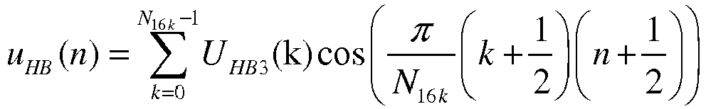
![]()
![]()
Dans le cas où le bloc 510 n'est pas une DCT, mais une autre transformation ou décomposition en sous-bandes, le bloc 502 réalise la synthèse correspondante à l'analyse réalisée dans le bloc 510.In the case where the
Le signal échantillonné à 16 kHz est ensuite de façon optionnelle mis à l'échelle par des gains définis par sous-trame de 80 échantillons (bloc 504).
Dans un mode de réalisation privilégié, on calcule d'abord (bloc 503) un gain gHB1(m) par sous-trame par des ratios d'énergie des sous-trames tel que dans chaque sous-trame d'indice m=0, 1, 2 ou 3 de la trame courante: 
![]()
![]()


Le bloc 504 effectue la mise à l'échelle du signal combiné (comprise dans l'étape E404a de la ![]()
In a preferred embodiment, we first calculate (block 503) a gain g HB1 (m) per sub-frame by energy ratios of the sub-frames such as in each sub-frame of index m = 0 , 1, 2 or 3 of the current frame:![]()
![]()
The ![]()
On notera que la réalisation du bloc 503 diffère de celle du bloc 101 de la
Ainsi, cette étape de mise à l'échelle permet de conserver dans la bande haute le ratio d'énergie entre la sous-trame et la trame de la même façon que dans la bande basse.
De façon optionnelle, le bloc 506 effectue ensuite la mise à l'échelle du signal (comprise dans l'étape E404a de la ![]()
Optionally, the ![]()
Enfin, le signal, uHB'(n) ou uHB"(n), est filtrée par le module de filtrage 507 qui peut être réalisé ici en prenant comme fonction de transfert 1/Â(z/γ), où γ=0.9 à 6.6 kbit/s et γ=0.6 aux autres débits, ce qui limite l'ordre du filtre à l'ordre 16.
Dans une variante, ce filtrage pourra être réalisé de la même façon que ce qui est décrit pour le bloc 111 de la
In a variant, this filtering could be carried out in the same way as what is described for
Dans des variantes de réalisation de l'invention, le codage de la bande basse (0-6.4 kHz) pourra être remplacé par un codeur CELP autre que celui utilisé dans AMR-WB, comme par exemple le codeur CELP dans G.718 à 8 kbit/s. Sans perte de généralité d'autres codeurs en bande élargie ou fonctionnant à des fréquences supérieurs à 16 kHz, dans lesquels le codage de la bande basse fonctionne à une fréquence interne à 12.8 kHz pourraient être utilisés. Par ailleurs, l'invention peut être adaptée de façon évidente à d'autres fréquences d'échantillonnage que 12.8 kHz, lorsqu'un codeur de basses fréquences fonctionne à une fréquence d'échantillonnage inférieure à celle du signal original ou reconstruit. Lorsque le décodage en bande basse n'utilise pas de prédiction linéaire, on ne dispose pas d'un signal d'excitation à étendre, dans ce cas on pourra réaliser une analyse LPC du signal reconstruit dans la trame courante et on calculera une excitation LPC de manière à pouvoir appliquer l'invention.In variant embodiments of the invention, the encoding of the low band (0-6.4 kHz) could be replaced by a CELP encoder other than that used in AMR-WB, such as for example the CELP encoder in G.718 to 8 kbit / s. Without loss of generality other wideband encoders or encoders operating at frequencies above 16 kHz, in which the low band encoding operates at an internal frequency of 12.8 kHz could be used. Furthermore, the invention can obviously be adapted to sampling frequencies other than 12.8 kHz, when a low frequency encoder operates at a sampling frequency lower than that of the original or reconstructed signal. When the low-band decoding does not use linear prediction, there is no excitation signal to extend, in this case an LPC analysis of the signal reconstructed in the current frame can be performed and an LPC excitation will be calculated. so as to be able to apply the invention.
Enfin, dans une autre variante de l'invention, l'excitation ou le signal bande basse ( u(n)) est ré-échantillonnée, par exemple par interpolation linéaire ou "spline" cubique, de 12.8 à 16 kHz avant transformation (par exemple DCT-IV) de longueur 320. Cette variante a le défaut d'être plus complexe, car la transformée (DCT-IV) de l'excitation ou du signal est alors calculée sur une plus grande longueur et le ré-échantillonnage n'est pas effectué dans le domaine de la transformée.Finally, in another variant of the invention, the excitation or the low band signal ( u ( n )) is resampled, for example by linear interpolation or cubic "spline", of 12.8 to 16 kHz before transformation (for example DCT-IV) of length 320. This variant has the drawback of being more complex, because the transform (DCT-IV) of the excitation or of the signal is then calculated on a larger length and resampling is not performed in the transform domain.
De plus, dans des variantes de l'invention, tous les calculs nécessaires à l'estimation des gains (GHBN , g HB1(m), gHB2 (m), gHBN ,...) pourront être effectués dans un domaine logarithmique.In addition, in variants of the invention, all the calculations necessary for estimating the gains ( G HBN , g HB 1 ( m ) , g HB2 ( m ), g HBN , etc.) can be carried out in a logarithmic domain.
La
Ce type de dispositif comporte un processeur PROC coopérant avec un bloc mémoire BM comportant une mémoire de stockage et/ou de travail MEM.
Un tel dispositif comporte un module d'entrée E apte à recevoir un signal audio décodé ou extrait dans une première bande de fréquence dite bande basse ramené dans le domaine fréquentiel (U(k)). Il comporte un module de sortie S apte à transmettre le signal d'extension dans une deuxième bande de fréquence (U HB2(k)) par exemple à un module de filtrage 501 de la
Such a device comprises an input module E capable of receiving a decoded or extracted audio signal in a first frequency band called the low band brought back to the frequency domain ( U ( k )) . It comprises an output module S capable of transmitting the extension signal in a second frequency band ( U HB 2 ( k )) for example to a
Le bloc mémoire peut avantageusement comporter un programme informatique comportant des instructions de code pour la mise en œuvre des étapes du procédé de d'extension de bande au sens de l'invention, lorsque ces instructions sont exécutées par le processeur PROC, et notamment les étapes d'extraction (E402) de composantes tonales et d'un signal d'ambiance à partir d'un signal issu du signal bande basse décodé (U(k)), de combinaison (E403) des composantes tonales (y(k)) et du signal d'ambiance (UHBA (k)) par mixage adaptatif utilisant des facteurs de contrôle de niveau d'énergie pour obtenir un signal audio, dit signal combiné (U HB2(k)), d'extension (E401a) sur au moins une deuxième bande de fréquence supérieure à la première bande de fréquence du signal décodé bande basse avant l'étape d'extraction ou du signal combiné après l'étape de combinaison.The memory block can advantageously comprise a computer program comprising code instructions for the implementation of the steps of the band extension method within the meaning of the invention, when these instructions are executed by the processor PROC, and in particular the steps extracting (E402) tonal components and a surround signal from a signal from the decoded low-band signal ( U ( k )) , combining (E403) tonal components (y (k)) and the surround signal (U HBA ( k )) by adaptive mixing using energy level control factors to obtain an audio signal, called the combined signal ( U HB 2 ( k )), of extension (E401a) on at least a second frequency band greater than the first frequency band of the low-band decoded signal before the extraction step or of the combined signal after the combining step.
Typiquement, la description de la
La mémoire MEM enregistre de manière générale, toutes les données nécessaires à la mise en œuvre du procédé.The memory MEM generally records all the data necessary for the implementation of the method.
Dans un mode possible de réalisation, le dispositif ainsi décrit peut également comporter les fonctions de décodage bande basse et autre fonctions de traitement décrites par exemple en
Claims (9)
- Method for extending the frequency band of an audio-frequency signal during a decoding or improvement process, comprising a step of obtaining the decoded signal in a first frequency band, referred to as a low band, the method comprising
the following steps performed in the frequency domain:• extraction (E402) of tonal components and of an ambient signal from a signal originating from the decoded low band signal;• combination (E403) of the tonal components and the ambient signal by adaptive mixing using energy-level control factors to obtain a combined signal;• extension (E401a) on at least one second frequency band greater than the first frequency band the decoded low band signal before the extraction step or the combined signal after the combination step• synthesis (E404b) of an audio signal to bring into the time domain:the method being characterised in that the step of extracting the tonal components and the ambient signal is performed according to the following steps:- the combined signal if the extension step (E401a) is performed before the extraction step (E402), or- the extended combined signal if the extension step (E401a) is performed after the combination step (E403) ;• obtaining the ambient signal by calculating an average value of the spectrum of the decoded or decoded and extended low band signal;• obtaining the tonal components by subtracting the calculated ambient signal from the decoded or decoded and extended low band signal. - Method according to claim 1, characterised in that the decoded low band signal is a decoded low band excitation signal.
- Method according to claim 1, characterised in that an energy-level control factor used for the adaptive mixing is calculated as a function of the total energy of the decoded or decoded and extended low band signal and of the tonal components.
- Method according to any one of the preceding claims, characterised in that the decoded low band signal undergoes a step of decomposition into sub-bands by transform or filter bank, the extraction and combination steps then taking place in the frequency domain or in sub-bands.
- Method according to any one of the preceding claims, characterised in that the extension step of the decoded low band signal is performed according to the following equation:

- Device for extending the frequency band of an audio-frequency signal, wherein the signal has been decoded in a first frequency band, referred to as a low band, the device comprising:- a module for extraction (512), in the frequency domain, of the tonal components and an ambient signal from a signal originating from the decoded low band signal;- a module for combination (513), in the frequency domain, of the tonal components and the ambient signal by adaptive mixing using energy-level control factors to obtain a combined signal;- a module for extension (511), in the frequency domain, on at least one second frequency band greater than the first frequency band implemented on the decoded low band signal before the extraction module or on the combined signal after the combination module;- a module for synthesis (502) of an audio signal to bring into the time domain:the device being characterised in that the module for extraction of the tonal components and the ambient signal is configured• the combined signal if the module for extension (511) is implemented before the module for extraction (512), or• the extended combined signal if the module for extension (511) is implemented after the module for extraction (513);- to obtain the ambient signal by calculating an average value of the spectrum of the decoded or decoded and extended low band signal;- to obtain tonal components by subtracting the calculated ambient signal from the decoded or decoded and extended low band signal.
- Audio-frequency signal decoder characterised in that it comprises a frequency band extension device according to claim 6.
- Computer program comprising code instructions for the implementation of steps of the frequency band extension method according to any one of claims 1 to 5, when these instructions are executed by a processor.
- Storage medium readable by a frequency band extension device on which a computer program is recorded, comprising code instructions for the execution of the steps of the frequency band extension method according to any one of claims 1 to 5.
Priority Applications (8)
| Application Number | Priority Date | Filing Date | Title |
|---|---|---|---|
| EP17206567.4A EP3330967B1 (en) | 2014-02-07 | 2015-02-04 | Improved frequency band extension in an audio frequency signal decoder |
| DK17206563.3T DK3330966T3 (en) | 2014-02-07 | 2015-02-04 | IMPROVED FREQUENCY BAND SPREADING IN A DECODER FOR AUDIO FREQUENCY SIGNALS |
| PL15705687T PL3103116T3 (en) | 2014-02-07 | 2015-02-04 | Improved frequency band extension in an audio signal decoder |
| RS20210945A RS62160B1 (en) | 2014-02-07 | 2015-02-04 | Improved frequency band extension in an audio signal decoder |
| EP17206563.3A EP3330966B1 (en) | 2014-02-07 | 2015-02-04 | Improved frequency band extension in an audio frequency signal decoder |
| EP17206569.0A EP3327722B1 (en) | 2014-02-07 | 2015-02-04 | Improved frequency band extension in an audio frequency signal decoder |
| SI201531646T SI3103116T1 (en) | 2014-02-07 | 2015-02-04 | Improved frequency band extension in an audio signal decoder |
| HRP20211187TT HRP20211187T1 (en) | 2014-02-07 | 2021-07-23 | Improved frequency band extension in an audio signal decoder |
Applications Claiming Priority (2)
| Application Number | Priority Date | Filing Date | Title |
|---|---|---|---|
| FR1450969A FR3017484A1 (en) | 2014-02-07 | 2014-02-07 | ENHANCED FREQUENCY BAND EXTENSION IN AUDIO FREQUENCY SIGNAL DECODER |
| PCT/FR2015/050257 WO2015118260A1 (en) | 2014-02-07 | 2015-02-04 | Improved frequency band extension in an audio signal decoder |
Related Child Applications (6)
| Application Number | Title | Priority Date | Filing Date |
|---|---|---|---|
| EP17206563.3A Division-Into EP3330966B1 (en) | 2014-02-07 | 2015-02-04 | Improved frequency band extension in an audio frequency signal decoder |
| EP17206563.3A Division EP3330966B1 (en) | 2014-02-07 | 2015-02-04 | Improved frequency band extension in an audio frequency signal decoder |
| EP17206567.4A Division-Into EP3330967B1 (en) | 2014-02-07 | 2015-02-04 | Improved frequency band extension in an audio frequency signal decoder |
| EP17206567.4A Division EP3330967B1 (en) | 2014-02-07 | 2015-02-04 | Improved frequency band extension in an audio frequency signal decoder |
| EP17206569.0A Division-Into EP3327722B1 (en) | 2014-02-07 | 2015-02-04 | Improved frequency band extension in an audio frequency signal decoder |
| EP17206569.0A Division EP3327722B1 (en) | 2014-02-07 | 2015-02-04 | Improved frequency band extension in an audio frequency signal decoder |
Publications (2)
| Publication Number | Publication Date |
|---|---|
| EP3103116A1 EP3103116A1 (en) | 2016-12-14 |
| EP3103116B1 true EP3103116B1 (en) | 2021-05-05 |
Family
ID=51014390
Family Applications (4)
| Application Number | Title | Priority Date | Filing Date |
|---|---|---|---|
| EP17206563.3A Active EP3330966B1 (en) | 2014-02-07 | 2015-02-04 | Improved frequency band extension in an audio frequency signal decoder |
| EP17206569.0A Active EP3327722B1 (en) | 2014-02-07 | 2015-02-04 | Improved frequency band extension in an audio frequency signal decoder |
| EP17206567.4A Active EP3330967B1 (en) | 2014-02-07 | 2015-02-04 | Improved frequency band extension in an audio frequency signal decoder |
| EP15705687.0A Active EP3103116B1 (en) | 2014-02-07 | 2015-02-04 | Improved frequency band extension in an audio signal decoder |
Family Applications Before (3)
| Application Number | Title | Priority Date | Filing Date |
|---|---|---|---|
| EP17206563.3A Active EP3330966B1 (en) | 2014-02-07 | 2015-02-04 | Improved frequency band extension in an audio frequency signal decoder |
| EP17206569.0A Active EP3327722B1 (en) | 2014-02-07 | 2015-02-04 | Improved frequency band extension in an audio frequency signal decoder |
| EP17206567.4A Active EP3330967B1 (en) | 2014-02-07 | 2015-02-04 | Improved frequency band extension in an audio frequency signal decoder |
Country Status (21)
| Country | Link |
|---|---|
| US (5) | US10043525B2 (en) |
| EP (4) | EP3330966B1 (en) |
| JP (4) | JP6625544B2 (en) |
| KR (5) | KR102510685B1 (en) |
| CN (4) | CN107993667B (en) |
| BR (2) | BR122017027991B1 (en) |
| DK (2) | DK3330966T3 (en) |
| ES (2) | ES2955964T3 (en) |
| FI (1) | FI3330966T3 (en) |
| FR (1) | FR3017484A1 (en) |
| HR (2) | HRP20231164T1 (en) |
| HU (2) | HUE055111T2 (en) |
| LT (2) | LT3330966T (en) |
| MX (1) | MX363675B (en) |
| PL (2) | PL3330966T3 (en) |
| PT (2) | PT3330966T (en) |
| RS (2) | RS64614B1 (en) |
| RU (4) | RU2763481C2 (en) |
| SI (2) | SI3330966T1 (en) |
| WO (1) | WO2015118260A1 (en) |
| ZA (3) | ZA201606173B (en) |
Families Citing this family (8)
| Publication number | Priority date | Publication date | Assignee | Title |
|---|---|---|---|---|
| RU2618919C2 (en) * | 2013-01-29 | 2017-05-12 | Фраунхофер-Гезелльшафт Цур Фердерунг Дер Ангевандтен Форшунг Е.Ф. | Device and method for audio synthesizing, decoder, encoder, system and computer program |
| FR3017484A1 (en) * | 2014-02-07 | 2015-08-14 | Orange | ENHANCED FREQUENCY BAND EXTENSION IN AUDIO FREQUENCY SIGNAL DECODER |
| EP2980794A1 (en) * | 2014-07-28 | 2016-02-03 | Fraunhofer-Gesellschaft zur Förderung der angewandten Forschung e.V. | Audio encoder and decoder using a frequency domain processor and a time domain processor |
| EP3382702A1 (en) * | 2017-03-31 | 2018-10-03 | Fraunhofer-Gesellschaft zur Förderung der angewandten Forschung e.V. | Apparatus and method for determining a predetermined characteristic related to an artificial bandwidth limitation processing of an audio signal |
| US10681486B2 (en) * | 2017-10-18 | 2020-06-09 | Htc Corporation | Method, electronic device and recording medium for obtaining Hi-Res audio transfer information |
| EP3518562A1 (en) * | 2018-01-29 | 2019-07-31 | Fraunhofer-Gesellschaft zur Förderung der angewandten Forschung e.V. | Audio signal processor, system and methods distributing an ambient signal to a plurality of ambient signal channels |
| KR102308077B1 (en) * | 2019-09-19 | 2021-10-01 | 에스케이텔레콤 주식회사 | Method and Apparatus for Artificial Band Conversion Based on Learning Model |
| JP2023509201A (en) * | 2020-01-13 | 2023-03-07 | ホアウェイ・テクノロジーズ・カンパニー・リミテッド | Audio encoding and decoding method and audio encoding and decoding device |
Family Cites Families (52)
| Publication number | Priority date | Publication date | Assignee | Title |
|---|---|---|---|---|
| CN1225736A (en) * | 1996-07-03 | 1999-08-11 | 英国电讯有限公司 | Voice activity detector |
| SE9700772D0 (en) * | 1997-03-03 | 1997-03-03 | Ericsson Telefon Ab L M | A high resolution post processing method for a speech decoder |
| TW430778B (en) * | 1998-06-15 | 2001-04-21 | Yamaha Corp | Voice converter with extraction and modification of attribute data |
| JP4135240B2 (en) * | 1998-12-14 | 2008-08-20 | ソニー株式会社 | Receiving apparatus and method, communication apparatus and method |
| US6226616B1 (en) * | 1999-06-21 | 2001-05-01 | Digital Theater Systems, Inc. | Sound quality of established low bit-rate audio coding systems without loss of decoder compatibility |
| JP4792613B2 (en) * | 1999-09-29 | 2011-10-12 | ソニー株式会社 | Information processing apparatus and method, and recording medium |
| US6704711B2 (en) * | 2000-01-28 | 2004-03-09 | Telefonaktiebolaget Lm Ericsson (Publ) | System and method for modifying speech signals |
| DE10041512B4 (en) * | 2000-08-24 | 2005-05-04 | Infineon Technologies Ag | Method and device for artificially expanding the bandwidth of speech signals |
| WO2003003345A1 (en) * | 2001-06-29 | 2003-01-09 | Kabushiki Kaisha Kenwood | Device and method for interpolating frequency components of signal |
| EP1701340B1 (en) * | 2001-11-14 | 2012-08-29 | Panasonic Corporation | Decoding device, method and program |
| DE60212696T2 (en) * | 2001-11-23 | 2007-02-22 | Koninklijke Philips Electronics N.V. | BANDWIDTH MAGNIFICATION FOR AUDIO SIGNALS |
| US20030187663A1 (en) * | 2002-03-28 | 2003-10-02 | Truman Michael Mead | Broadband frequency translation for high frequency regeneration |
| CN1318231C (en) * | 2002-06-28 | 2007-05-30 | 倍耐力轮胎公司 | System and method for monitoring characteristic parameters of a tyre |
| US6845360B2 (en) * | 2002-11-22 | 2005-01-18 | Arbitron Inc. | Encoding multiple messages in audio data and detecting same |
| WO2006107833A1 (en) * | 2005-04-01 | 2006-10-12 | Qualcomm Incorporated | Method and apparatus for vector quantizing of a spectral envelope representation |
| WO2006132054A1 (en) * | 2005-06-08 | 2006-12-14 | Matsushita Electric Industrial Co., Ltd. | Apparatus and method for widening audio signal band |
| FR2888699A1 (en) * | 2005-07-13 | 2007-01-19 | France Telecom | HIERACHIC ENCODING / DECODING DEVICE |
| US7546237B2 (en) * | 2005-12-23 | 2009-06-09 | Qnx Software Systems (Wavemakers), Inc. | Bandwidth extension of narrowband speech |
| CN101089951B (en) * | 2006-06-16 | 2011-08-31 | 北京天籁传音数字技术有限公司 | Band spreading coding method and device and decode method and device |
| JP5141180B2 (en) * | 2006-11-09 | 2013-02-13 | ソニー株式会社 | Frequency band expanding apparatus, frequency band expanding method, reproducing apparatus and reproducing method, program, and recording medium |
| KR101379263B1 (en) * | 2007-01-12 | 2014-03-28 | 삼성전자주식회사 | Method and apparatus for decoding bandwidth extension |
| US8229106B2 (en) * | 2007-01-22 | 2012-07-24 | D.S.P. Group, Ltd. | Apparatus and methods for enhancement of speech |
| US8489396B2 (en) * | 2007-07-25 | 2013-07-16 | Qnx Software Systems Limited | Noise reduction with integrated tonal noise reduction |
| US8041577B2 (en) * | 2007-08-13 | 2011-10-18 | Mitsubishi Electric Research Laboratories, Inc. | Method for expanding audio signal bandwidth |
| ATE535904T1 (en) * | 2007-08-27 | 2011-12-15 | Ericsson Telefon Ab L M | IMPROVED TRANSFORMATION CODING OF VOICE AND AUDIO SIGNALS |
| EP2210427B1 (en) * | 2007-09-26 | 2015-05-06 | Fraunhofer-Gesellschaft zur Förderung der angewandten Forschung e.V. | Apparatus, method and computer program for extracting an ambient signal |
| US8688441B2 (en) * | 2007-11-29 | 2014-04-01 | Motorola Mobility Llc | Method and apparatus to facilitate provision and use of an energy value to determine a spectral envelope shape for out-of-signal bandwidth content |
| KR20100086000A (en) * | 2007-12-18 | 2010-07-29 | 엘지전자 주식회사 | A method and an apparatus for processing an audio signal |
| ATE500588T1 (en) * | 2008-01-04 | 2011-03-15 | Dolby Sweden Ab | AUDIO ENCODERS AND DECODERS |
| US8600740B2 (en) * | 2008-01-28 | 2013-12-03 | Qualcomm Incorporated | Systems, methods and apparatus for context descriptor transmission |
| DE102008015702B4 (en) * | 2008-01-31 | 2010-03-11 | Fraunhofer-Gesellschaft zur Förderung der angewandten Forschung e.V. | Apparatus and method for bandwidth expansion of an audio signal |
| US8831936B2 (en) * | 2008-05-29 | 2014-09-09 | Qualcomm Incorporated | Systems, methods, apparatus, and computer program products for speech signal processing using spectral contrast enhancement |
| KR101381513B1 (en) * | 2008-07-14 | 2014-04-07 | 광운대학교 산학협력단 | Apparatus for encoding and decoding of integrated voice and music |
| US8532983B2 (en) * | 2008-09-06 | 2013-09-10 | Huawei Technologies Co., Ltd. | Adaptive frequency prediction for encoding or decoding an audio signal |
| US8352279B2 (en) * | 2008-09-06 | 2013-01-08 | Huawei Technologies Co., Ltd. | Efficient temporal envelope coding approach by prediction between low band signal and high band signal |
| PL2945159T3 (en) * | 2008-12-15 | 2018-08-31 | Fraunhofer-Gesellschaft zur Förderung der angewandten Forschung e.V. | Audio encoder and bandwidth extension decoder |
| US8463599B2 (en) * | 2009-02-04 | 2013-06-11 | Motorola Mobility Llc | Bandwidth extension method and apparatus for a modified discrete cosine transform audio coder |
| RU2452044C1 (en) * | 2009-04-02 | 2012-05-27 | Фраунхофер-Гезелльшафт цур Фёрдерунг дер ангевандтен Форшунг Е.Ф. | Apparatus, method and media with programme code for generating representation of bandwidth-extended signal on basis of input signal representation using combination of harmonic bandwidth-extension and non-harmonic bandwidth-extension |
| CN101990253A (en) * | 2009-07-31 | 2011-03-23 | 数维科技(北京)有限公司 | Bandwidth expanding method and device |
| JP5493655B2 (en) | 2009-09-29 | 2014-05-14 | 沖電気工業株式会社 | Voice band extending apparatus and voice band extending program |
| CN102612712B (en) * | 2009-11-19 | 2014-03-12 | 瑞典爱立信有限公司 | Bandwidth extension of low band audio signal |
| JP5589631B2 (en) * | 2010-07-15 | 2014-09-17 | 富士通株式会社 | Voice processing apparatus, voice processing method, and telephone apparatus |
| US9047875B2 (en) * | 2010-07-19 | 2015-06-02 | Futurewei Technologies, Inc. | Spectrum flatness control for bandwidth extension |
| KR101826331B1 (en) * | 2010-09-15 | 2018-03-22 | 삼성전자주식회사 | Apparatus and method for encoding and decoding for high frequency bandwidth extension |
| MX2013009303A (en) * | 2011-02-14 | 2013-09-13 | Fraunhofer Ges Forschung | Audio codec using noise synthesis during inactive phases. |
| US20140019125A1 (en) * | 2011-03-31 | 2014-01-16 | Nokia Corporation | Low band bandwidth extended |
| EP2791937B1 (en) | 2011-11-02 | 2016-06-08 | Telefonaktiebolaget LM Ericsson (publ) | Generation of a high band extension of a bandwidth extended audio signal |
| ES2762325T3 (en) * | 2012-03-21 | 2020-05-22 | Samsung Electronics Co Ltd | High frequency encoding / decoding method and apparatus for bandwidth extension |
| US9228916B2 (en) * | 2012-04-13 | 2016-01-05 | The Regents Of The University Of California | Self calibrating micro-fabricated load cells |
| KR101897455B1 (en) * | 2012-04-16 | 2018-10-04 | 삼성전자주식회사 | Apparatus and method for enhancement of sound quality |
| US9666202B2 (en) * | 2013-09-10 | 2017-05-30 | Huawei Technologies Co., Ltd. | Adaptive bandwidth extension and apparatus for the same |
| FR3017484A1 (en) * | 2014-02-07 | 2015-08-14 | Orange | ENHANCED FREQUENCY BAND EXTENSION IN AUDIO FREQUENCY SIGNAL DECODER |
-
2014
- 2014-02-07 FR FR1450969A patent/FR3017484A1/en active Pending
-
2015
- 2015-02-04 CN CN201711459702.6A patent/CN107993667B/en active Active
- 2015-02-04 PL PL17206563.3T patent/PL3330966T3/en unknown
- 2015-02-04 HU HUE15705687A patent/HUE055111T2/en unknown
- 2015-02-04 ES ES17206563T patent/ES2955964T3/en active Active
- 2015-02-04 SI SI201531958T patent/SI3330966T1/en unknown
- 2015-02-04 EP EP17206563.3A patent/EP3330966B1/en active Active
- 2015-02-04 RU RU2017144522A patent/RU2763481C2/en active
- 2015-02-04 RU RU2017144523A patent/RU2763547C2/en active
- 2015-02-04 SI SI201531646T patent/SI3103116T1/en unknown
- 2015-02-04 BR BR122017027991-2A patent/BR122017027991B1/en active IP Right Grant
- 2015-02-04 KR KR1020227007471A patent/KR102510685B1/en active IP Right Grant
- 2015-02-04 CN CN201711459695.XA patent/CN108109632B/en active Active
- 2015-02-04 PT PT172065633T patent/PT3330966T/en unknown
- 2015-02-04 US US15/117,100 patent/US10043525B2/en active Active
- 2015-02-04 HU HUE17206563A patent/HUE062979T2/en unknown
- 2015-02-04 HR HRP20231164TT patent/HRP20231164T1/en unknown
- 2015-02-04 CN CN201711459701.1A patent/CN108022599B/en active Active
- 2015-02-04 JP JP2016549732A patent/JP6625544B2/en active Active
- 2015-02-04 MX MX2016010214A patent/MX363675B/en unknown
- 2015-02-04 RS RS20230844A patent/RS64614B1/en unknown
- 2015-02-04 RU RU2016136008A patent/RU2682923C2/en active
- 2015-02-04 CN CN201580007250.0A patent/CN105960675B/en active Active
- 2015-02-04 LT LTEP17206563.3T patent/LT3330966T/en unknown
- 2015-02-04 KR KR1020177037706A patent/KR102380487B1/en active IP Right Grant
- 2015-02-04 RU RU2017144521A patent/RU2763848C2/en active
- 2015-02-04 LT LTEP15705687.0T patent/LT3103116T/en unknown
- 2015-02-04 WO PCT/FR2015/050257 patent/WO2015118260A1/en active Application Filing
- 2015-02-04 EP EP17206569.0A patent/EP3327722B1/en active Active
- 2015-02-04 FI FIEP17206563.3T patent/FI3330966T3/en active
- 2015-02-04 BR BR112016017616-2A patent/BR112016017616B1/en active IP Right Grant
- 2015-02-04 RS RS20210945A patent/RS62160B1/en unknown
- 2015-02-04 KR KR1020167024350A patent/KR102380205B1/en active IP Right Grant
- 2015-02-04 EP EP17206567.4A patent/EP3330967B1/en active Active
- 2015-02-04 ES ES15705687T patent/ES2878401T3/en active Active
- 2015-02-04 KR KR1020177037710A patent/KR102426029B1/en active IP Right Grant
- 2015-02-04 EP EP15705687.0A patent/EP3103116B1/en active Active
- 2015-02-04 PL PL15705687T patent/PL3103116T3/en unknown
- 2015-02-04 DK DK17206563.3T patent/DK3330966T3/en active
- 2015-02-04 PT PT157056870T patent/PT3103116T/en unknown
- 2015-02-04 KR KR1020177037700A patent/KR20180002906A/en not_active IP Right Cessation
- 2015-02-04 DK DK15705687.0T patent/DK3103116T3/en active
-
2016
- 2016-09-06 ZA ZA2016/06173A patent/ZA201606173B/en unknown
-
2017
- 2017-12-11 ZA ZA2017/08368A patent/ZA201708368B/en unknown
- 2017-12-11 ZA ZA2017/08366A patent/ZA201708366B/en unknown
-
2018
- 2018-01-12 US US15/869,560 patent/US10668760B2/en active Active
- 2018-06-18 US US16/011,153 patent/US10730329B2/en active Active
-
2019
- 2019-06-07 JP JP2019107007A patent/JP6775063B2/en active Active
- 2019-06-07 JP JP2019107008A patent/JP6775064B2/en active Active
- 2019-06-07 JP JP2019107009A patent/JP6775065B2/en active Active
-
2020
- 2020-07-13 US US16/926,818 patent/US11312164B2/en active Active
- 2020-07-27 US US16/939,104 patent/US11325407B2/en active Active
-
2021
- 2021-07-23 HR HRP20211187TT patent/HRP20211187T1/en unknown
Also Published As
Similar Documents
| Publication | Publication Date | Title |
|---|---|---|
| EP3020043B1 (en) | Optimized scale factor for frequency band extension in an audiofrequency signal decoder | |
| EP3103116B1 (en) | Improved frequency band extension in an audio signal decoder | |
| EP3014611B1 (en) | Improved frequency band extension in an audio signal decoder | |
| WO2014009657A1 (en) | Processing method for improving the quality of audio frequency signals |
Legal Events
| Date | Code | Title | Description |
|---|---|---|---|
| PUAI | Public reference made under article 153(3) epc to a published international application that has entered the european phase |
Free format text: ORIGINAL CODE: 0009012 |
|
| STAA | Information on the status of an ep patent application or granted ep patent |
Free format text: STATUS: REQUEST FOR EXAMINATION WAS MADE |
|
| 17P | Request for examination filed |
Effective date: 20160804 |
|
| AK | Designated contracting states |
Kind code of ref document: A1 Designated state(s): AL AT BE BG CH CY CZ DE DK EE ES FI FR GB GR HR HU IE IS IT LI LT LU LV MC MK MT NL NO PL PT RO RS SE SI SK SM TR |
|
| AX | Request for extension of the european patent |
Extension state: BA ME |
|
| RIN1 | Information on inventor provided before grant (corrected) |
Inventor name: KANIEWSKA, MAGDALENA Inventor name: RAGOT, STEPHANE |
|
| DAX | Request for extension of the european patent (deleted) | ||
| STAA | Information on the status of an ep patent application or granted ep patent |
Free format text: STATUS: EXAMINATION IS IN PROGRESS |
|
| 17Q | First examination report despatched |
Effective date: 20170720 |
|
| RAP1 | Party data changed (applicant data changed or rights of an application transferred) |
Owner name: KONINKLIJKE PHILIPS N.V. |
|
| RAP1 | Party data changed (applicant data changed or rights of an application transferred) |
Owner name: KONINKLIJKE PHILIPS N.V. |
|
| GRAP | Despatch of communication of intention to grant a patent |
Free format text: ORIGINAL CODE: EPIDOSNIGR1 |
|
| STAA | Information on the status of an ep patent application or granted ep patent |
Free format text: STATUS: GRANT OF PATENT IS INTENDED |
|
| INTG | Intention to grant announced |
Effective date: 20201123 |
|
| GRAS | Grant fee paid |
Free format text: ORIGINAL CODE: EPIDOSNIGR3 |
|
| GRAA | (expected) grant |
Free format text: ORIGINAL CODE: 0009210 |
|
| STAA | Information on the status of an ep patent application or granted ep patent |
Free format text: STATUS: THE PATENT HAS BEEN GRANTED |
|
| AK | Designated contracting states |
Kind code of ref document: B1 Designated state(s): AL AT BE BG CH CY CZ DE DK EE ES FI FR GB GR HR HU IE IS IT LI LT LU LV MC MK MT NL NO PL PT RO RS SE SI SK SM TR |
|
| REG | Reference to a national code |
Ref country code: GB Ref legal event code: FG4D Free format text: NOT ENGLISH |
|
| REG | Reference to a national code |
Ref country code: CH Ref legal event code: EP |
|
| REG | Reference to a national code |
Ref country code: AT Ref legal event code: REF Ref document number: 1390825 Country of ref document: AT Kind code of ref document: T Effective date: 20210515 |
|
| REG | Reference to a national code |
Ref country code: DE Ref legal event code: R096 Ref document number: 602015068913 Country of ref document: DE |
|
| REG | Reference to a national code |
Ref country code: IE Ref legal event code: FG4D Free format text: LANGUAGE OF EP DOCUMENT: FRENCH |
|
| REG | Reference to a national code |
Ref country code: PT Ref legal event code: SC4A Ref document number: 3103116 Country of ref document: PT Date of ref document: 20210712 Kind code of ref document: T Free format text: AVAILABILITY OF NATIONAL TRANSLATION Effective date: 20210705 |
|
| REG | Reference to a national code |
Ref country code: RO Ref legal event code: EPE |
|
| REG | Reference to a national code |
Ref country code: HR Ref legal event code: TUEP Ref document number: P20211187T Country of ref document: HR |
|
| REG | Reference to a national code |
Ref country code: DK Ref legal event code: T3 Effective date: 20210721 |
|
| REG | Reference to a national code |
Ref country code: NL Ref legal event code: FP Ref country code: FI Ref legal event code: FGE |
|
| REG | Reference to a national code |
Ref country code: SE Ref legal event code: TRGR |
|
| REG | Reference to a national code |
Ref country code: GR Ref legal event code: EP Ref document number: 20210401962 Country of ref document: GR Effective date: 20210813 |
|
| REG | Reference to a national code |
Ref country code: EE Ref legal event code: FG4A Ref document number: E021177 Country of ref document: EE Effective date: 20210719 |
|
| REG | Reference to a national code |
Ref country code: NO Ref legal event code: T2 Effective date: 20210505 |
|
| REG | Reference to a national code |
Ref country code: SK Ref legal event code: T3 Ref document number: E 37832 Country of ref document: SK |
|
| REG | Reference to a national code |
Ref country code: HU Ref legal event code: AG4A Ref document number: E055111 Country of ref document: HU |
|
| REG | Reference to a national code |
Ref country code: HR Ref legal event code: T1PR Ref document number: P20211187 Country of ref document: HR |
|
| REG | Reference to a national code |
Ref country code: ES Ref legal event code: FG2A Ref document number: 2878401 Country of ref document: ES Kind code of ref document: T3 Effective date: 20211118 |
|
| REG | Reference to a national code |
Ref country code: DE Ref legal event code: R097 Ref document number: 602015068913 Country of ref document: DE |
|
| REG | Reference to a national code |
Ref country code: HR Ref legal event code: ODRP Ref document number: P20211187 Country of ref document: HR Payment date: 20220127 Year of fee payment: 8 |
|
| PLBE | No opposition filed within time limit |
Free format text: ORIGINAL CODE: 0009261 |
|
| STAA | Information on the status of an ep patent application or granted ep patent |
Free format text: STATUS: NO OPPOSITION FILED WITHIN TIME LIMIT |
|
| 26N | No opposition filed |
Effective date: 20220208 |
|
| PG25 | Lapsed in a contracting state [announced via postgrant information from national office to epo] |
Ref country code: AL Free format text: LAPSE BECAUSE OF FAILURE TO SUBMIT A TRANSLATION OF THE DESCRIPTION OR TO PAY THE FEE WITHIN THE PRESCRIBED TIME-LIMIT Effective date: 20210505 |
|
| PGFP | Annual fee paid to national office [announced via postgrant information from national office to epo] |
Ref country code: MK Payment date: 20220125 Year of fee payment: 8 |
|
| REG | Reference to a national code |
Ref country code: AT Ref legal event code: UEP Ref document number: 1390825 Country of ref document: AT Kind code of ref document: T Effective date: 20210505 |
|
| REG | Reference to a national code |
Ref country code: HR Ref legal event code: ODRP Ref document number: P20211187 Country of ref document: HR Payment date: 20230124 Year of fee payment: 9 |
|
| REG | Reference to a national code |
Ref country code: FR Ref legal event code: PLFP Year of fee payment: 9 |
|
| PGFP | Annual fee paid to national office [announced via postgrant information from national office to epo] |
Ref country code: NL Payment date: 20230222 Year of fee payment: 9 |
|
| PGFP | Annual fee paid to national office [announced via postgrant information from national office to epo] |
Ref country code: SM Payment date: 20230221 Year of fee payment: 9 Ref country code: RO Payment date: 20230206 Year of fee payment: 9 Ref country code: NO Payment date: 20230216 Year of fee payment: 9 Ref country code: MC Payment date: 20230216 Year of fee payment: 9 Ref country code: LU Payment date: 20230222 Year of fee payment: 9 Ref country code: LT Payment date: 20230124 Year of fee payment: 9 Ref country code: IE Payment date: 20230215 Year of fee payment: 9 Ref country code: FR Payment date: 20230223 Year of fee payment: 9 Ref country code: FI Payment date: 20230223 Year of fee payment: 9 Ref country code: ES Payment date: 20230321 Year of fee payment: 9 Ref country code: DK Payment date: 20230223 Year of fee payment: 9 Ref country code: CZ Payment date: 20230203 Year of fee payment: 9 Ref country code: CH Payment date: 20230307 Year of fee payment: 9 Ref country code: BG Payment date: 20230224 Year of fee payment: 9 Ref country code: AT Payment date: 20230215 Year of fee payment: 9 |
|
| PGFP | Annual fee paid to national office [announced via postgrant information from national office to epo] |
Ref country code: TR Payment date: 20230124 Year of fee payment: 9 Ref country code: SK Payment date: 20230124 Year of fee payment: 9 Ref country code: SI Payment date: 20230124 Year of fee payment: 9 Ref country code: SE Payment date: 20230222 Year of fee payment: 9 Ref country code: RS Payment date: 20230124 Year of fee payment: 9 Ref country code: PT Payment date: 20230123 Year of fee payment: 9 Ref country code: PL Payment date: 20230125 Year of fee payment: 9 Ref country code: LV Payment date: 20230223 Year of fee payment: 9 Ref country code: IT Payment date: 20230220 Year of fee payment: 9 Ref country code: IS Payment date: 20230222 Year of fee payment: 9 Ref country code: HU Payment date: 20230127 Year of fee payment: 9 Ref country code: HR Payment date: 20230124 Year of fee payment: 9 Ref country code: GR Payment date: 20230220 Year of fee payment: 9 Ref country code: GB Payment date: 20230214 Year of fee payment: 9 Ref country code: EE Payment date: 20230222 Year of fee payment: 9 Ref country code: DE Payment date: 20220628 Year of fee payment: 9 Ref country code: BE Payment date: 20230222 Year of fee payment: 9 |
|
| P01 | Opt-out of the competence of the unified patent court (upc) registered |
Effective date: 20230523 |
|
| PGFP | Annual fee paid to national office [announced via postgrant information from national office to epo] |
Ref country code: MT Payment date: 20230227 Year of fee payment: 9 |
|
| PGFP | Annual fee paid to national office [announced via postgrant information from national office to epo] |
Ref country code: AL Payment date: 20230227 Year of fee payment: 9 |
|
| REG | Reference to a national code |
Ref country code: HR Ref legal event code: ODRP Ref document number: P20211187 Country of ref document: HR Payment date: 20240123 Year of fee payment: 10 |
|
| PGFP | Annual fee paid to national office [announced via postgrant information from national office to epo] |
Ref country code: MK Payment date: 20230126 Year of fee payment: 9 |
|
| PGFP | Annual fee paid to national office [announced via postgrant information from national office to epo] |
Ref country code: LU Payment date: 20240226 Year of fee payment: 10 |
|
| PGFP | Annual fee paid to national office [announced via postgrant information from national office to epo] |
Ref country code: GR Payment date: 20240221 Year of fee payment: 10 |
|
| PGFP | Annual fee paid to national office [announced via postgrant information from national office to epo] |
Ref country code: IS Payment date: 20240229 Year of fee payment: 10 |