EP3102976B1 - System and method for imaging with pinhole arrays - Google Patents
System and method for imaging with pinhole arrays Download PDFInfo
- Publication number
- EP3102976B1 EP3102976B1 EP15746767.1A EP15746767A EP3102976B1 EP 3102976 B1 EP3102976 B1 EP 3102976B1 EP 15746767 A EP15746767 A EP 15746767A EP 3102976 B1 EP3102976 B1 EP 3102976B1
- Authority
- EP
- European Patent Office
- Prior art keywords
- radiation
- aperture
- image data
- mask
- image
- Prior art date
- Legal status (The legal status is an assumption and is not a legal conclusion. Google has not performed a legal analysis and makes no representation as to the accuracy of the status listed.)
- Not-in-force
Links
Images


Classifications
-
- H—ELECTRICITY
- H04—ELECTRIC COMMUNICATION TECHNIQUE
- H04N—PICTORIAL COMMUNICATION, e.g. TELEVISION
- H04N13/00—Stereoscopic video systems; Multi-view video systems; Details thereof
- H04N13/10—Processing, recording or transmission of stereoscopic or multi-view image signals
- H04N13/106—Processing image signals
- H04N13/133—Equalising the characteristics of different image components, e.g. their average brightness or colour balance
-
- G—PHYSICS
- G01—MEASURING; TESTING
- G01T—MEASUREMENT OF NUCLEAR OR X-RADIATION
- G01T1/00—Measuring X-radiation, gamma radiation, corpuscular radiation, or cosmic radiation
- G01T1/29—Measurement performed on radiation beams, e.g. position or section of the beam; Measurement of spatial distribution of radiation
- G01T1/2914—Measurement of spatial distribution of radiation
- G01T1/2921—Static instruments for imaging the distribution of radioactivity in one or two dimensions; Radio-isotope cameras
- G01T1/295—Static instruments for imaging the distribution of radioactivity in one or two dimensions; Radio-isotope cameras using coded aperture devices, e.g. Fresnel zone plates
-
- G—PHYSICS
- G02—OPTICS
- G02B—OPTICAL ELEMENTS, SYSTEMS OR APPARATUS
- G02B26/00—Optical devices or arrangements for the control of light using movable or deformable optical elements
- G02B26/06—Optical devices or arrangements for the control of light using movable or deformable optical elements for controlling the phase of light
-
- G—PHYSICS
- G02—OPTICS
- G02B—OPTICAL ELEMENTS, SYSTEMS OR APPARATUS
- G02B27/00—Optical systems or apparatus not provided for by any of the groups G02B1/00 - G02B26/00, G02B30/00
- G02B27/42—Diffraction optics, i.e. systems including a diffractive element being designed for providing a diffractive effect
- G02B27/46—Systems using spatial filters
-
- G—PHYSICS
- G02—OPTICS
- G02B—OPTICAL ELEMENTS, SYSTEMS OR APPARATUS
- G02B30/00—Optical systems or apparatus for producing three-dimensional [3D] effects, e.g. stereoscopic images
- G02B30/20—Optical systems or apparatus for producing three-dimensional [3D] effects, e.g. stereoscopic images by providing first and second parallax images to an observer's left and right eyes
- G02B30/22—Optical systems or apparatus for producing three-dimensional [3D] effects, e.g. stereoscopic images by providing first and second parallax images to an observer's left and right eyes of the stereoscopic type
- G02B30/24—Optical systems or apparatus for producing three-dimensional [3D] effects, e.g. stereoscopic images by providing first and second parallax images to an observer's left and right eyes of the stereoscopic type involving temporal multiplexing, e.g. using sequentially activated left and right shutters
-
- G—PHYSICS
- G02—OPTICS
- G02B—OPTICAL ELEMENTS, SYSTEMS OR APPARATUS
- G02B5/00—Optical elements other than lenses
- G02B5/20—Filters
- G02B5/201—Filters in the form of arrays
-
- G—PHYSICS
- G06—COMPUTING OR CALCULATING; COUNTING
- G06T—IMAGE DATA PROCESSING OR GENERATION, IN GENERAL
- G06T5/00—Image enhancement or restoration
- G06T5/80—Geometric correction
-
- H—ELECTRICITY
- H04—ELECTRIC COMMUNICATION TECHNIQUE
- H04N—PICTORIAL COMMUNICATION, e.g. TELEVISION
- H04N13/00—Stereoscopic video systems; Multi-view video systems; Details thereof
- H04N13/10—Processing, recording or transmission of stereoscopic or multi-view image signals
- H04N13/106—Processing image signals
- H04N13/122—Improving the 3D impression of stereoscopic images by modifying image signal contents, e.g. by filtering or adding monoscopic depth cues
-
- H—ELECTRICITY
- H04—ELECTRIC COMMUNICATION TECHNIQUE
- H04N—PICTORIAL COMMUNICATION, e.g. TELEVISION
- H04N13/00—Stereoscopic video systems; Multi-view video systems; Details thereof
- H04N13/20—Image signal generators
- H04N13/204—Image signal generators using stereoscopic image cameras
- H04N13/207—Image signal generators using stereoscopic image cameras using a single 2D image sensor
- H04N13/211—Image signal generators using stereoscopic image cameras using a single 2D image sensor using temporal multiplexing
-
- H—ELECTRICITY
- H04—ELECTRIC COMMUNICATION TECHNIQUE
- H04N—PICTORIAL COMMUNICATION, e.g. TELEVISION
- H04N13/00—Stereoscopic video systems; Multi-view video systems; Details thereof
- H04N13/20—Image signal generators
- H04N13/204—Image signal generators using stereoscopic image cameras
- H04N13/207—Image signal generators using stereoscopic image cameras using a single 2D image sensor
- H04N13/218—Image signal generators using stereoscopic image cameras using a single 2D image sensor using spatial multiplexing
-
- G—PHYSICS
- G02—OPTICS
- G02B—OPTICAL ELEMENTS, SYSTEMS OR APPARATUS
- G02B2207/00—Coding scheme for general features or characteristics of optical elements and systems of subclass G02B, but not including elements and systems which would be classified in G02B6/00 and subgroups
- G02B2207/129—Coded aperture imaging
-
- G—PHYSICS
- G21—NUCLEAR PHYSICS; NUCLEAR ENGINEERING
- G21K—TECHNIQUES FOR HANDLING PARTICLES OR IONISING RADIATION NOT OTHERWISE PROVIDED FOR; IRRADIATION DEVICES; GAMMA RAY OR X-RAY MICROSCOPES
- G21K1/00—Arrangements for handling particles or ionising radiation, e.g. focusing or moderating
- G21K1/02—Arrangements for handling particles or ionising radiation, e.g. focusing or moderating using diaphragms, collimators
- G21K1/04—Arrangements for handling particles or ionising radiation, e.g. focusing or moderating using diaphragms, collimators using variable diaphragms, shutters, choppers
-
- H—ELECTRICITY
- H04—ELECTRIC COMMUNICATION TECHNIQUE
- H04N—PICTORIAL COMMUNICATION, e.g. TELEVISION
- H04N13/00—Stereoscopic video systems; Multi-view video systems; Details thereof
- H04N2013/0074—Stereoscopic image analysis
- H04N2013/0081—Depth or disparity estimation from stereoscopic image signals
-
- H—ELECTRICITY
- H04—ELECTRIC COMMUNICATION TECHNIQUE
- H04N—PICTORIAL COMMUNICATION, e.g. TELEVISION
- H04N13/00—Stereoscopic video systems; Multi-view video systems; Details thereof
- H04N2013/0074—Stereoscopic image analysis
- H04N2013/0092—Image segmentation from stereoscopic image signals
Definitions
- the invention is in the field of radiation imaging and relates to imaging techniques utilizing pinhole arrays.
- Pinhole optics may provide various advantages over the common use of lens systems, such as reducing linear distortion, providing virtually infinite depth of focus and wide angular field of view. Additionally, pinhole imaging is useful for non-optical radiation frequencies, such as X-rays, Gamma radiation and basically any wave- or particle-like phenomena.
- Imaging characteristics of a pinhole generally depend inter alia on the cross-sectional dimension (diameter) of the pinhole.
- the resulting image is typically in the form of a uniform disc being a geometrical shadow of the pinhole.
- the resulting image is a Fresnel or Fraunhofer diffraction pattern.
- Intermediate pinhole sizes can provide imaging of a scene.
- An optimal pinhole diameter can be determined as a compromise between the large spot image of the large pinhole and the wide diffraction pattern of the small pinhole size.
- pinhole size affects image resolution, contrast, brightness, exposure times, and signal to noise ratio.
- WO 2010/119,447 describes an optical system for use with a predetermined light detection surface comprising a multitude of light sensitive pixels.
- the optical system comprises an optical window defining a predetermined light transmission pattern formed by a multiple spaced apart light transmissive regions, configured in accordance with said multitude of light sensitive pixels.
- the configuration of said multiple spaced apart light transmissive regions define an irregular arrangement of said regions with respect to said multitude of light sensitive pixels.
- Said optical window with said irregular arrangement is configured for collecting light beams from different directions from a scenery to be imaged and for directing, on each of said light sensitive pixels, the light component formed by a distinct set of light intensities, corresponding to said light beams collected from different directions, thereby providing spatially distinct light intensity patterns overlapped on said light detection surface and corresponding to said light beams collected from different directions.
- US 6,545,265B describes a method for mixing pairs of confocal images and different arrangements for fast generation of parallel confocal images and the combination thereof in real time.
- the method is used for improving contrast and resolution in confocal images.
- the suggested arrangements point to some possibilities for a meaningful application of the method for image mixing in parallel confocal single-beam or double-beam methods for the generation of highly resolved images in real time for a wide variety of different applications, especially also for material inspection.
- a resolution of the fine structure of the object is achieved in the mixed image. Contrast, lateral resolution and depth resolution are improved in the mixed image of the object to be examined, which can also be a phase object.
- the method permits the generation of very highly resolved three-dimensional digital images of optical objects to be examined.
- US 2006/279,845 describes an optical system comprised of a monolithic microlens array assembly that consists of two groups of microlenses sub-assemblies having different pitches between the adjacent lenses.
- a ratio between the pitches of sub-assemblies is determined by a predetermined relationship between the parameters of the optical system so that the microlenses of the first sub-assembly create a plurality of individual intermediate images arranged side-by-side in a common intermediate plane that are transferred by the microlenses of the second sub-assembly to the final image plane in the form of a plurality of identical and accurately registered images interposed onto each other. This is achieved due to the aforementioned ratio between the pitches.
- the technique of the present invention allows for producing high quality image data of a region of interest utilizing two or more arrays of pinholes, each array having a predetermined different arrangement of pinholes.
- the arrangements of pinholes in the two or more arrays are selected to provide desired total effective transmission function of radiation collection during two or more image acquisition steps through respectively said two or more pinhole arrays.
- pinhole based imaging requires selection between image resolution (optical resolution) and intensity (energy), and according to the convention approach the improvement of one of this factor is unavoidably on the cost of the other.
- the technique of the present invention allows utilizing the benefits of pinhole imaging, for imaging with optical as well as non-optical radiation, while providing greater input intensity without reducing the resolution achieved. This is achieved in the technique of the present invention by utilizing the concept of pinhole imaging in combination with spatial and temporal image multiplexing to provide efficient imaging and enabling high quality reconstruction of the image data.
- input radiation (optical or non-optical) propagating from a region of interest is collected by an imaging system for a predetermined total exposure time.
- the input radiation is being sequentially imaged through a set of two or more pinhole (aperture) arrays for corresponding time periods.
- Each pinhole array is a mask formed by a radiation blocking surface having a preselected arrangement of one or more pinholes of predetermined dimensions and shape allowing transmission of radiation.
- the set of pinhole arrays comprises two or more pinhole arrays (e.g. masks having predetermined number of pinholes), each comprising an arrangement of predetermined number of pinholes of selected desired dimension(s) and geometry/shape(s).
- pinhole arrays e.g. masks having predetermined number of pinholes
- For each array radiation collected by the pinholes results in multiple overlapping images on an imaging plane (of a detector).
- the multiplicity of such overlapping images is collected for predetermined exposure time.
- a sequence of two or more input image data pieces are produced via collection of input radiation by the two or more pinhole arrays, respectively, each image data piece corresponding to a selected pinhole array and a selected collection (exposure) time.
- the image data pieces are then processed based on the arrangement of the pinholes in each array and exposure time(s) defining together the total effective transmission function, to determine a restored image data indicative of the region of interest.
- radiation transmission through an array of two or more pinholes generates loss of information due to interference of radiation portions passing through the different pinholes. This can be seen in a spectrum of spatial frequency transmission associated with the pinhole array and having one or more spatial frequencies with zero transmission.
- the technique of the present invention utilizes a set of two or more pinhole arrays selected such that if one of the arrays has zero or low transmission for a certain spatial frequency within desired resolution limits, one or more other arrays of the set is/are configured to have higher transmission at said spatial frequency, such that the total effective transmission function provides non-null transmission for all spatial frequencies within desired resolution limits.
- the proper selection of aperture arrays such that cumulative transmission of the set forms an effective transmission function with non-null values within the desired resolution limits.
- This selection of the set of aperture arrays also provides for relatively simple and efficient post processing of the input image data to generate restored image of the region of interest. The processing just utilizes data about the total effective transmission function and its inverse operator for image reconstruction.
- a method for imaging a region of interest comprising:
- the set of aperture arrays is selected such that transmission functions of the aperture arrays have zero values at different spatial frequencies, thereby providing said total effective transmission function having non-null transmission for spatial frequencies being lower than a predetermined maximal spatial frequency.
- this maximal spatial frequency may be defined by a minimal aperture size.
- the minimal aperture size defining the maximal spatial frequency may be selected in accordance with geometrical resolution of image detection.
- the corresponding collection time periods of the selected aperture arrays are selected for optimizing transmission intensities for selected spatial frequencies.
- the method may further comprise: detecting said image data pieces using a single readout mode for all of said collection time periods of the aperture arrays, thereby integrating said image data pieces to form the image data in one scan time while selectively using the different aperture arrays.
- a dedicated readout session may be utilized for each aperture array and the resulting image data pieces may be summed numerically.
- processing of the image data pieces for restoring the image of the region of interest may comprise: receiving or determining a sum of intensity maps of said image data pieces and utilizing inverting the distortion effect caused by the total effective transmission function, to thereby generate said restored image data.
- the processing may comprise utilizing a Weiner deconvolution of the effective transmission function.
- the restored image data may be determined in spatial frequency domain.
- the method of the invention may be used with input radiation being electromagnetic radiation in at least one of the following spectra: infra-red radiation, visible light, ultra violet radiation, x-ray radiation, and gamma radiation.
- said processing of the image data pieces for determining the restored image data may further comprises: providing a set of at least two different depth resolved effective transmission functions each corresponding to the collection of the input radiation from an object plane of the region of interest located at a different distance from said set of the aperture arrays; for each of the depth resolved effective transmission functions, determining a partially restored image data piece corresponding to the respective object plane; and generating data indicative of a three-dimensional restored image of the region of interest.
- the at least two different depth resolved effective transmission functions may be determined based on virtual aperture arrangement in accordance with varying magnification for imaging from selected object planes.
- the set of aperture arrays and the corresponding arrangement of apertures thereof may be selected in accordance of a desired Radiation Intensity Improvement (RII) factor to provide imaging of the region of interest with improved image brightness.
- RII Radiation Intensity Improvement
- the selection of said set of a plurality of a predetermined number of aperture arrays and the corresponding arrangement of apertures thereof may comprise: determining desired resolution for imaging and a corresponding minimal aperture dimension; determining the shape and angle of each aperture, determining a number of aperture to provide desired brightness of imaging; determining said predetermined number of arrays; determining aperture arrangement in each array to provide non-null total effective transmission function of the set of aperture arrays.
- Determining of the aperture arrangement may comprise: determining aperture arrangement of a first array; determining a corresponding effective transmission function; identifying spatial frequencies for which said effective transmission function provides transmission lower than a predetermined threshold; and determining one or more additional aperture arrangement such that transmission of said one or more of the additional aperture arrangement at said identified spatial frequencies is above a predetermined threshold.
- an imaging system comprising:
- the selected plurality of a predetermined number of spatial filtering patterns of the mask are preselected providing transmission functions of the spatial filtering patterns having zero values at different spatial frequencies, thereby providing said effective transmission function with non-null transmission for spatial frequencies lower than a desired predetermined maximal spatial frequency.
- the mask may be configured as a replaceable mask comprising plurality of a predetermined number of spatial filtering patterns such that the mask may be configured to selectively place a selected spatial filtering pattern on the radiation collection surface of the mask.
- the mask may be configured as a mechanical wheel comprising said two or more aperture arrays each defining a corresponding filtering pattern.
- the mask may be configured as a radiation transmission modulator and configured to electronically vary filtering pattern thereof.
- the mask may comprise a multiplexed arrangement of apertures corresponding to said predetermined number of spatial filtering patterns, said multiplexed arrangement of apertures may comprise groups of apertures corresponding to different filtering patterns, each group of apertures comprises a wavelength selective filter configured for transmission of a predetermined wavelength range being a part of a total wavelength range for imaging.
- the processor unit may further comprise a set selection module configured to be responsive to input data comprising data about desired resolution and brightness and to determine a corresponding set of filtering patterns having non-null effective transmission function.
- the processor unit may further comprise a depth resolution pre-processing module configured to determine depth resolved effective transmission function in accordance with aperture arrangement of the set of filtering patterns.
- the image processing module may be configured and operable to determined a plurality of restored depth resolved image data pieces, each of the depth resolved restored image data pieces corresponds to a selected object plane in accordance with a corresponding depth resolved effective transmission function, thereby providing three-dimensional information about the region of interest.
- the system may be configured for imaging with input radiation of at least one of the following wavelength ranges: IR radiation, visible light radiation, UV radiation, X-ray radiation, Gamma radiation.
- a method for use in pinhole based imaging comprising: determining a pinhole dimension based on data about: locations of object plane, location of image plane and desired maximal resolution; determining a desired number of apertures based on desired image brightness per time unit; selecting a first aperture array comprising one or more apertures of the desired dimension; determining a first set of spatial frequency values for which transmission of said first aperture array is below a predetermined threshold; determining at least one additional aperture array having aperture arrangement providing that transmission at said first set of spatial frequencies is above a corresponding predetermined threshold; wherein a total number of apertures divided by a total number of arrays provides a factor for said desired brightness per time unit.
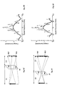
- Figs. 1A and 1B there schematically shown the principles of pinhole based imaging of an object 2 in a region of interest using single- and multipinhole imaging system.
- input radiation coming from the object 2 e.g. emitted or reflected from the object
- the radiation collection surface is defined by a mask 10 in the form of radiation blocking surface having an aperture 5 of a predetermined dimension and shape.
- radiation transmission through the aperture 5 provides an inverted image 8 of the object 2 in the image plane, which can be viewed on a screen or collected by a detector.
- the imaging system provides magnification based on a ratio between the distance Z of the object plane 2 to the aperture mask 10 and the distance U of the image plane (screen, detector) and the mask 10 (i.e. radiation collecting surface).
- magnification based on a ratio between the distance Z of the object plane 2 to the aperture mask 10 and the distance U of the image plane (screen, detector) and the mask 10 (i.e. radiation collecting surface).
- M U Z
- Additional parameters, such as image resolution and brightness, are determined by dimension (e.g. diameter) of the pinhole in relation to the wavelength of radiation used and the distance to the image plane U .
- the angular separation (minimal difference in angular orientation if two features visible as separated on the image plane) is selected to be as small as possible.
- far-field distance is defined as a distance between the object plane and the radiation collecting surface being large enough such that a phase difference between the radiation components collected at the opposite ends of an aperture is much less than the wavelength, i.e. the wavefront of the radiation from the object plane arriving at the radiation collection surface is substantially planar. In such distance individual contributions of radiation components interacting with the pinholes can be treated as though they are substantially parallel.
- far-field distance is significantly greater than W 2 / ⁇ , where ⁇ is the wavelength and W is the largest dimension of the aperture.
- the Fraunhofer equations can be used to model the diffraction effects of the radiation passage through the pinhole in such far-field distances.
- generally far-field is defined when the distance from the object plane to the pinhole mask is larger than the area of the apertures in the mask divided by the wavelength of radiation used.
- near-field condition exists when the distance from the object plane to the mask is smaller than the ratio of the largest aperture's area and the wavelength.
- pinhole imaging according to the conventional approach has an inherent tradeoff between image resolution and brightness limiting the uses thereof.
- FIG. 1B illustrates imaging of an object 2 through a mask 10 having two apertures 5a and 5b .
- imaging system may provide similar image resolution while twice the collected intensity.
- the two apertures are not separated enough, the two images 8a and 8b are overlapping. This reduces the ability to differentiate between spatial features in the collected image.
- the present invention provides a novel approach for use in pinhole based imaging, while enabling to increase image brightness without the need to sacrifice resolution.
- Fig. 2 illustrating a system 100 for pinhole based imaging of a region of interest.
- the system 100 includes a mask unit 120 formed by at least one physical mask defining a radiation collection surface for input radiation arriving from the region of interest, and a processor unit 160 .
- the radiation collection is performed by sequentially or selectively collecting radiation with different arrays of pinholes (i.e. different spatial filtering patterns).
- This may generally be implemented by replacing a mask (pattern) in the radiation collection path.
- the mask 120 may include a single mask configured and operable to define two or more different spatial filtering patterns and selectively collect input radiation with one selected spatial filtering pattern at a time (i.e. during a collection session).
- the mask has radiation transmitting regions (pinholes, apertures, windows) arranged in spaced-apart relationship within the radiation collecting surface. It should be noted that such radiation transmitting regions spaced by blocking regions may be implemented as a passive mask or electronic mask (spatial radiation modulator).
- the light collecting surface may be planar, i.e. all the radiation transmitting regions are located in substantially the same plane, or may not be planar such that different radiation transmitting regions are located in different planes.
- the latter may be implemented by providing a certain surface relief of the mask or by making the radiation transmitting regions at different depths of the mask.
- such radiation transmitting regions are referred to as apertures or pinholes.
- each of the spatial filtering patterns is formed by a predetermined arrangement of spatially separated apertures in the collection surface.
- the mask 120 may include (or operated to define in case of electronic mask) two or more pinhole arrays (three arrays 10a-10c are shown in the figure), each defining a different spatial filtering pattern, and may be associated with a suitable mechanism for selectively utilizing each of the different pinhole arrays for collection of input radiation.
- the mask 120 may for example be configured as a rotating plate, as will be described further below, made with apertures such that displacement of the plate results in that one of the two or more patterns is involved in the radiation collection, i.e. is in the active region of the mask with respect to the radiation propagation.
- a spatial radiation modulator such as spatial light modulator SLM that may include suitable polarizers on each aperture thereof
- SLM spatial light modulator
- the mask 120 may be in the form of single plate having plurality of apertures of two or more groups (arrays); each group of apertures defines a spatial filtering pattern.
- each of the aperture groups may include a wavelength selective filter allowing transmission of input radiation of a wavelength range being part of the spectrum used for imaging, thus providing multiplexed selective filtering of input radiation.
- the mask 120 includes two or more pinhole arrays, e.g. 10a and 10b , each configured with a selected predetermined number and arrangement of pinholes of predetermined dimensions and shapes.
- input radiation from the region of interest is collected through a selected set of a plurality of a predetermined number of aperture arrays, where each array has a predetermined arrangement of apertures and is operated to collect the input radiation during a collection time period.
- the selected set of the aperture arrays defines a predetermined total effective transmission function of the radiation collection.
- the corresponding collection time periods for the aperture arrays are selected to further optimize the image quality.
- image data piece is created, to thereby generate image data of the cumulative radiation collection sessions through the set of aperture arrays.
- the image data is processed utilizing the data about the total effective transmission function of the radiation collection, and a restored image of the region of interest is determined.
- the set of aperture arrays is selected such that the total effective transmission function provides non-null transmission for spatial frequencies lower than a predetermined maximal spatial frequency.
- the maximal spatial frequency is typically defined by a minimal aperture size, which may in turn be selected in accordance with geometrical resolution of image detection.
- the collection time periods of the selected aperture arrays are selected for optimizing transmission intensities for selected spatial frequencies.
- the processor unit 160 may be connected to the mask assembly 120 for controlling its operation for selectively utilizing the different aperture/pinhole arrays for collection of input radiation (e.g. shifting / rotating the mask to place a different aperture array in the radiation collection path). Additionally, the processor unit 160 may be connectable to a detector 140 which may be a constructional part of the system or not, for receiving detector output indicative of the image data pieces generated from input radiation impinging on the radiation sensing surface of the detector 140.
- the processor unit 160 may thus include a filtering controller module 165 configured to operate the mask assembly 120 to sequentially select a spatial filtering pattern to be used for light collection session (e.g. select a pinhole/aperture array such as 10a, 10b or 10c in Fig. 2 ) .
- a filtering controller module 165 configured to operate the mask assembly 120 to sequentially select a spatial filtering pattern to be used for light collection session (e.g. select a pinhole/aperture array such as 10a, 10b or 10c in Fig. 2 ) .
- an image acquisition module 170 configured for receiving image data pieces generated by the detector 140 in response to collected input radiation for a selected collection time period.
- the processor unit 160 further includes an image processing module 180 configured for receiving the image data pieces from the image acquisition module 170 and processing the image data pieces to determine a restored image data of the region of interest.
- the system may be configured for determining data indicative of a set (e.g. sequence) of spatial filtering patterns to be used in the radiation collection sessions, using a set selection module 190 being part of the processor unit 160 or a separate control unit.
- the set selection module 190 is configured to select and determine the set of aperture arrays, as will be described further below. Alternatively, such data about the set of aperture array and their corresponding collection time periods may be previously determined and provided as input data to the system.
- the processor unit may also include a depth resolving pre-processor 195 configured for determining a so-called depth resolved total effective transmission functions corresponding to radiation collection through the above-described set of aperture arrays from different locations respectively of the object plane. This will also be described more specifically further below.
- FIG. 3 Figs 4A-4C and Fig. 5 exemplifying three mask assembly configurations providing three filtering patterns each formed by an aperture array.
- Fig. 3 shows a mask assembly formed by a single rotating mask 120 having three (generally two or more) regions 10a, 10b and 10c each including a different array of apertures, i.e. different apertures' arrangement providing a different spatial filtering pattern for the radiation being collected.
- the mask is, selectively rotatable about a rotation axis 12 to selectively place one of the regions 10a, 10b and 10c in radiation collection path.
- the number of the regions and the arrangement of apertures therein are selected to provide the desired total effective transmission function as described above.
- Figs. 4A-4C show a filtering mask assembly 120 which define a plurality of spaced-apart apertures, generally at 5.
- the mask assembly defines a single mask which is formed by two plates, P1 and P2 as shown in Fig. 4B , configured such that at least one plate is rotatable with respect to the other about an axis RA .
- Each plate is formed with multiple apertures. Relative rotation of the plates results in that each respective orientation of the plates creates a different active apertures' array (spatial filtering pattern) for use in radiation collection.
- one of the plates e.g.
- Figs . 4B and 4C exemplify the arrays resulting from the angular orientations between the plates of respectively 30° and 60° resulting in different active apertures arrays 10b and 10b .
- Fig. 5 exemplifies a different configuration of a mask assembly 120 .
- the mask assembly includes a mask with multiple apertures and a spectral filter aligned with and located close to the mask.
- the spectral filter is operable to have different spectral transmissions (illustrated here for simplicity by primary colors R, G, B) in different radiation collection sessions.
- the spectral transmissions may be such that the entire aperture provides transmission of one or more spectral bands.
- the number of the apertures and their arrangement are selected to provide the desired total effective transmission function as described above.
- the set of aperture arrays is arranged such that apertures are spaced also along an optical axis, i.e. are located in different planes of the radiation collection surface.
- the apertures are located such as to define pre-determined radiation collection plane, including a so-called primary collection plane U1, and at least one other plane located closer or further to the image plane as compared to the primary plane. In this example, three such collection planes are shows.
- the processor unit 160 and the image processing module 180 thereof utilize the image data pieces in the spatial frequency domain.
- a radiation transmission through a single array of pinholes may generally cause interference between radiation components passing through different pinholes of the array.
- the effective transmission function F ( u, ⁇ ) of a single pinhole array typically has zero transmission for certain spatial frequencies.
- the technique of the present invention utilizes a predetermined number of two or more aperture arrays.
- the filtering controller module 165 selects first aperture array and the image acquisition module 170 generates image data piece corresponding to radiation collection within exposure time t 1 , a second aperture array is used for collection of radiation from the same region of interest for exposure time of t 2 , and similarly for additional aperture arrays if used.
- a second aperture array is used for collection of radiation from the same region of interest for exposure time of t 2 , and similarly for additional aperture arrays if used.
- summation of the image data pieces may be done by the detector 140 collecting input radiation for the entire exposure time (i.e. exposed to input radiation during collection through all of the aperture arrays) and providing a "combined" readout of exposure, or by the image processing module 180 determining a sum of the image data piece provided by the detector 140 .
- the set of aperture arrays is selected such that the total effective transmission function G ( u, v ) provides non-null transmission for spatial frequencies up to a predetermined limit.
- a predetermined limit is determined by the maximal resolution obtained by radiation collection with a single pinhole of corresponding diameter. More specifically, the aperture arrays/masks and corresponding exposure times are selected to provide: G u v ⁇ 0 ⁇ u v ⁇ u ⁇ u max , v ⁇ v max
- the total effective transmission function is determined in accordance with the aperture arrays used by the imaging system 100 and corresponding exposure times.
- the sum of intensity maps of the image data pieces is determined, and then a distortion effect, caused by the total effective transmission function, is inverted to thereby generate the restored image data
- Wiener deconvolution is used for correction of noise addition to a convolution based problem.
- y ( r ) h(r) ⁇ x(r) + n(r)
- * convolution operator
- x(r) is the input signal (generally image data of the region of interest)
- h(r) is the impulse response of the system
- n(r) is an unknown signal such as noise
- y ( r ) is the observed/measured signal.
- G ⁇ 1 f H ⁇ f S f H f 2 S f + N f
- G -1 and H are Fourier transform of g -1 and h in the frequency domain f (spatial frequency)
- S ( f ) is the mean power spectral density of x ( r )
- N ( f ) is the mean power spectral density of the noise n ( r ) .
- G -1 as describe herein in equation 11 refers to the inverse effective transmission function according to the present technique and thus the (-1) superscript is used herein, differently than the general terms of wiener algorithm.
- the set of aperture arrays is selected to satisfy the condition that total effective transmission function is non-null for spatial frequencies within the desired resolution limits.
- zero (or close to zero) values of the effective transmission function may cause amplification of noise in the restored image data and reduce the signal to noise ratio.
- Fig. 7 exemplifying a method for selection of the set of aperture arrays for use in the imaging system 100 .
- the desired parameters of the system need to be determined.
- the resulting image resolution is determined (step 1010) in accordance with a diameter of the apertures, together with distance from mask to the detector F , from the objects to the mask Z and the wavelength of radiation used as described above with reference to equation 2.
- a minimal aperture diameter may be selected to define the desired resolution and one or more additional, larger diameters may be selected to further increase image brightness.
- a desired energy transmission is determined. The energy transmission may be determined as a factor of improvement with respect to a single pinhole system, or with respect to a standard optical imaging system.
- the energy transmission can be presented as Radiation Intensity Improvement (RII) factor which is used to determine the number of apertures in the arrays and the number of arrays used.
- the energy transmission is determined in accordance with detector sensitivity and appropriate accumulated exposure time.
- a general decision about number of aperture arrays and arrangement of the apertures in each array is to be made ( 1030 ). For example, for desired RII of 2, two aperture arrays may be used each having two apertures along an axis. Generally the number of aperture arrays is selected to be as low as possible while providing the desired condition of equation 9. Additionally, the aperture arrangement in each array may be 1-dimensional, i.e. apertures arranged along an axis, or 2-dimensional.
- an aperture arrangement for the first array is determined. It should be noted that the order of selection of the arrays is of no importance at the imaging session. Generally the aperture arrangement of the first array may be determined arbitrarily, however generally a simple arrangement of one aperture at the center of the radiation collection surface and one aperture at certain distance therefrom along a selected axis may be preferred. Generalization to two dimensional arrangements may be done by copying 1-dimensional arrangement along a second axis and/or rotation of such 1-dimensional arrangement.
- the corresponding effective transmission function is determined and the "problematic" spatial frequencies are marked ( 1050 ).
- additional aperture arrays may be determined ( 1060 ), the number and diameter of apertures is selected in accordance with desired resolution and energy transmission, while the arrangement of the apertures is determined to provide finite values of the corresponding effective transmission function for the spatial frequencies marked for the previous array(s) ( 1070 ). This process may be performed for two, three or more aperture arrays until an appropriate set of aperture arrays is selected ( 1080 ).
- the set of aperture arrays may be pre-selected for design and assembly of the imaging system.
- the processor unit 160 of imaging system 100 may further include a set selection unit ( 190 in Fig. 2 ) configured to determine an appropriate set of aperture arrays in accordance with input parameters about desired resolution and energy transmission.
- the former method is suitable for use with pinholes punctured into a radiation blocking mask, while the later is more suitable of use with electronically controlled varying patterned mask 120 .
- the selection of an appropriate set of aperture array is configured to optimize the transmission of the aperture arrays for different spatial frequencies.
- the selection process may also include determining an estimated total effective transmission function, assuming equal exposure times for all aperture arrays.
- the estimated effective transmission function may then be compared to a Pinhole Transmission Function (PTF).
- PTF Pinhole Transmission Function
- the set of aperture arrays is selected to optimize transmission of spatial frequencies with the resolution limits to thereby optimize imaging of the region of interest.
- the aperture arrays, as well as corresponding exposure times are selected such that for at least some spatial frequencies within the desired resolution limits, the total effective transmission function provides transmission that is greater than that of the PTF.
- the above described technique can also be utilized for acquiring 3-dimensional image data. More specifically, the technique allows obtaining of image data pieces from a region of interest and to determine depth information from the acquired image data pieces.
- the processor unit 160 of the imaging system 100 may utilize predetermined information about expected distances of objects within the region of interest as well as desired depth resolution to determine different effective transmission functions in accordance with the different distances.
- Such 3-dimensional information is typically more effective in near-field imaging as described above, however it should be noted that depth information may be determined based on image data pieces acquired by the system of the present invention even in the far-field.
- the processor unit 160 may thus include a depth resolving pre-processor 195 configured to determine variation of the effective transmission function in accordance with desired depth resolution to be extracted from the image data pieces.
- effective transmission function data corresponding to depth resolving of the imaging system may be pre-configured and provided to the system, e.g. stored in a corresponding storage unit.
- a new effective depth transmission function F ( l ) Z ( u , v ) can be defined for each array and each distance Z, as well as a new total effective depth transmission function G Z ′ u v .
- the image processing module 180 may utilize the depth resolved effective transmission functions provided by the depth resolution pre-processor 195 to determined plurality of restored image data sets, each indicative to object distance Z in connection with the corresponding effective transmission function G Z ′ u v for the distance.
- the number of Z planes obtained by corresponding effective depth transmission functions G Z ′ u v determine the depth resolution.
- the maximal possible depth resolution is determined by rules of triangulation and in accordance with geometrical resolution of the detector unit 140. In this connection, variation of the distance of an object from the mask can be detected if an image generated by radiation transmission through at least one of the apertures in at least one aperture array shifts by at least one pixel with respect to a distance of a reference object plane.
- the image processing unit 180 is configured to reconstruct image data for each of the Z -planes. For each reconstructed data only objects located in the corresponding Z -plane will be accurately reconstructed providing in-focus image data. Objects located in other Z -planes will provide blurry reconstructed image data similar to 'out-of-focus' image data.
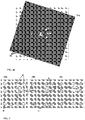
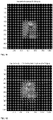
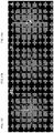
- Figs. 9A-9K show three aperture arrays, corresponding effective transmission functions and images of a test object.
- Fig. 9A-9C show aperture configuration of three aperture arrays having pinholes of diameter 170 ⁇ m;
- Fig. 6D illustrates the locations and numbering of the apertures.
- the set of aperture arrays is selected to provide 5.66 brighter imaging relative to a single pinhole of similar diameter.
- the locations of the apertures in the three arrays of Figs. 9A-9C are shown in table 1 in relative units determined in accordance with pixel size of the detector and distances in the system (i.e. U and Z ).
- apertures 1, 5 and 9 are located at the center of the mask and the rest of the apertures are arranged around to provide non-null effective transmission function.
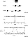
- Figs. 9E and 9F illustrate the absolute values of the effective transmission functions for each aperture array and the total effecting transmission function based on selected exposure time weights.
- graph line G 0 shows the transmission function of a single pinhole located at the center of the mask and having similar dimension.
- Graphs F 1 , F 2 and F 3 show the effective transmission function of aperture arrays of Figs. 9A-9C respectively.
- the effective transmission function of a single pinhole is in the form of sinc ( f ) function having a main lobe defining the resolution limits.
- Aperture array of Fig. 9A has several zero points while aperture arrays of Fig. 9B and 9C are designed to have zero values at different spatial frequencies in order to provide the total effective transmission function G total with non-null values for spatial resolutions within the resolution limits.
- the aperture arrays shown here are actually configured as replications of a one-dimensional array and thus the effective transmission function can be fully described in a 1D graph.
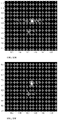
- Figs. 9G to 9K show experimental results illustrating the efficiency of the above described technique.
- Fig. 9G shows image of a test object taken with visible light through a single pinhole of diameter of 170 ⁇ m;
- Fig. 9H shows an image of the same object through a pinhole of diameter of 250 ⁇ m;
- Fig. 9I shows an image of the object through a pinhole of diameter of 350 ⁇ m;
- Fig. 9J shows raw image data generated after sequential exposure through the three aperture arrays of Figs. 9A-9C without post-processing; and
- Fig. 9K shows reconstructed image after post-processing.
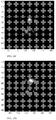
- Figs. 10A-10E show image data of simulation results using one-dimensional and two-dimensional aperture arrays configured as exemplified in Figs. 9A-9C .
- the one-dimensional aperture arrays were configured with aperture locations including apertures 1, 2; 5, 6; and 14, 9, 10 as exemplified in Fig. 9D and provide image brightness increase of 2.33.
- Fig. 10A shows an image taken through a single pinhole of similar diameter
- Fig. 10B shows a similar image taken through a pinhole diameter bigger by 150%
- Fig. 10C shows reconstructed image taken in accordance with the above described technique utilizing one-dimensional aperture arrays
- Figs. 10D and 10E show respectively raw image data and reconstructed image taken in accordance with the multi aperture technique utilizing two-dimensional aperture arrays.
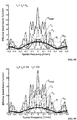
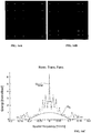
- FIG. 11A-11J illustrates simulation of Gamma imaging using the technique of the present invention.
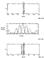
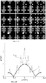
- Figs. 11A shows the structure of arrays 1-3 and corresponding aperture dimensions;
- Figs. 11B-11G show graphs of the arrays and corresponding effective transmission functions;
- Fig. 11H shows a single pinhole transmission as well the separate and total effective transmission functions of the arrays;
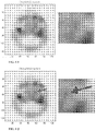
- Figs. 11I-11J show simulated images for imaging using a single pinhole ( Fig. 11I ) and reconstructed image ( Fig. 11J ) utilizing the technique of the invention with the pinhole arrays shown in Fig. 11A with conventional simulation techniques emulating bone scan for osteomyelitis transverse slice image (negative colors) using Gallium 67 radiation.
- Both Figs. 11I and 11J illustrated a region of the figure in magnification, and as shown, the reconstructed image provides higher resolution and signal to noise ratio and thus provides information on features (marked with an arrow) that cannot be resolved in the image generated by a
- the aperture arrays provide brightness increase of 2.33 with respect to a single pinhole system of similar diameter. As shown the aperture arrays are selected such that the total effective transmission function (G total in Fig. 11H ) in non-null for spatial frequencies within the resolution limits of the single pinhole dimensions.
- the signal to noise ratio (SNR) provided by the technique of the invention is significantly higher with respect to a single pinhole system.
- the improvement is greater than 2.33 , and is higher than 2.5 within similar exposure time and providing similar resolution limits.
- Figs. 12A-12C show experimental results of Gamma imaging of a resolution test object having a plurality of lead lines with different density on a surface.
- Fig. 12A shows image of the test object through a single pinhole of diameter of 4.45mm;
- Fig. 12B shows imaging of the test object using a single pinhole of diameter of 2mm;
- Fig. 12C shows reconstructed image of the test object utilizing the technique of the invention with a set of aperture arrays as shows in Fig. 12A with pinhole diameter of 2mm.
- the image of Fig. 12A is relatively bright but does not provide sufficient resolution to differentiate between the fine lines in two of the regions of the object.
- Utilizing a smaller pinhole, in Fig. 12B increases the resolution, however it limits the image brightness and thus for one of the regions, the brightness of the image is not sufficient in order to recognize the fine lines.
- Figs. 13A-13F show experimental depth resolved imaging based on the above described technique utilizing the aperture arrays of Fig. 11A .
- Fig. 13A shows a case having four radiation sources of different power located at different distances from the front surface of the case. The distance between the close sources and the further ones is 60mm
- Fig. 12B illustrates an imaging scheme and a side view of the sources' locations in the case to illustrate the different locations of the sources.
- Fig. 12C shows an image of the object as generated by imaging through a single pinhole of 2mm in diameter. In this image all four radiation sources can be seen with limited resolution and brightness.
- Fig. 13D shows a raw image resulting of collecting radiation through three aperture arrays as sown in Fig. 11A .
- This image is blurry and requires reconstruction to provide meaningful information.
- Such information is provides in Figs. 13E and 13F showing image reconstruction results for Z max and Z min distances respectively.
- the distances are defined in accordance of existing knowledge of thickness of the object being image and desired depth resolution. As shown, in each restored image there are two sources marked clearly and a multiplicity of points resulting from input radiation from the sources of the other location.
- This technique allows the use of X-ray and Gamma imaging for localizing of tumors or other radiation sources without the need to collect plurality of images from different locations. And in general to reduce radiation collection time thus allowing the use of faster decaying radiation sources and reduce the damage to the subjects.
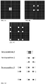
- Figs. 14A-14C as well as Figs. 15A-15D show alternative aperture array arrangement suitable for use with the technique of the present invention. As described above, the arrangement of apertures in the aperture arrays is selected to provide non-null transmission in all spatial frequencies within the desired resolution limits.
- Figs. 14A and 14B show a set of two aperture arrays, each having 25 apertures in a predetermined arrangement providing together an effective transmission function with finite transmission in all spatial frequencies within the resolution of a single pinhole of the corresponding diameter as well as beyond that resolution.
- the absolute value of the total effective transmission function is shown in Fig. 14C .
- This graph shows the total effective transmission function G total with respect to transmission of a single pinhole of a similar diameter G 0 .
- Such set of aperture arrays provide RII of 25 and thus increases brightness of imaging 25 times with respect to imaging through a single pinhole. Alternatively, this technique can be used to provide similar brightness with reduces exposure time.
- Figs. 15A-15D exemplify the use of aperture arrays having different pinhole diameters.
- Fig. 15A shows three sets of aperture arrays of similar arrangement.
- Set I is similar to the aperture arrangement described in Figs. 9A-9D and Table 1.
- Sets II is configured with additional apertures and set III provides apertures of different diameters to allow higher brightness.
- Figs. 15B to 15D show respective total effective transmission functions with respect to transmission of a single pinhole.
- Fig. 15B is the total effective transmission of set I
- Fig. 15C shows the total effective transmission function of set II
- Fig. 15D shows the total effective transmission function of set III.
- the use of additional apertures provides the total effective transmission to be greater in modulus with respect to the transmission of a single pinhole for more spatial frequencies.
- the present invention provide a technique and system for imaging a region of interest through two or more aperture arrays and for reconstruction of the acquired image data to provide reconstructed images of the region of interest.
- the technique can be used with any wavelength of electromagnetic radiation including, but not limited to, infra-red radiation, visible light radiation, ultra violet radiation, X-ray radiation, Gamma radiation or any other wavelength where a blocking material can be used.
- the technique may also be used to provide depth information based on image data without the need to move the imaging system or the object.
Landscapes
- Physics & Mathematics (AREA)
- General Physics & Mathematics (AREA)
- Engineering & Computer Science (AREA)
- Signal Processing (AREA)
- Multimedia (AREA)
- Optics & Photonics (AREA)
- High Energy & Nuclear Physics (AREA)
- Spectroscopy & Molecular Physics (AREA)
- Molecular Biology (AREA)
- Life Sciences & Earth Sciences (AREA)
- Health & Medical Sciences (AREA)
- Theoretical Computer Science (AREA)
- Image Processing (AREA)
- Studio Devices (AREA)
- Geometry (AREA)
- General Engineering & Computer Science (AREA)
Applications Claiming Priority (2)
| Application Number | Priority Date | Filing Date | Title |
|---|---|---|---|
| US201461936402P | 2014-02-06 | 2014-02-06 | |
| PCT/IL2015/050135 WO2015118540A1 (en) | 2014-02-06 | 2015-02-05 | System and method for imaging with pinhole arrays |
Publications (3)
| Publication Number | Publication Date |
|---|---|
| EP3102976A1 EP3102976A1 (en) | 2016-12-14 |
| EP3102976A4 EP3102976A4 (en) | 2017-09-13 |
| EP3102976B1 true EP3102976B1 (en) | 2020-10-07 |
Family
ID=53777401
Family Applications (1)
| Application Number | Title | Priority Date | Filing Date |
|---|---|---|---|
| EP15746767.1A Not-in-force EP3102976B1 (en) | 2014-02-06 | 2015-02-05 | System and method for imaging with pinhole arrays |
Country Status (5)
| Country | Link |
|---|---|
| US (2) | US10033996B2 (enExample) |
| EP (1) | EP3102976B1 (enExample) |
| JP (1) | JP6605483B2 (enExample) |
| IL (1) | IL246832B (enExample) |
| WO (1) | WO2015118540A1 (enExample) |
Families Citing this family (21)
| Publication number | Priority date | Publication date | Assignee | Title |
|---|---|---|---|---|
| EP2822472B1 (en) | 2012-03-07 | 2022-09-28 | Ziteo, Inc. | Systems for tracking and guiding sensors and instruments |
| US10045752B2 (en) * | 2012-05-14 | 2018-08-14 | The General Hospital Corporation | Method for coded-source phase contrast X-ray imaging |
| US10617401B2 (en) | 2014-11-14 | 2020-04-14 | Ziteo, Inc. | Systems for localization of targets inside a body |
| WO2016123529A1 (en) * | 2015-01-29 | 2016-08-04 | William Marsh Rice University | Lensless imaging system using an image sensor with one or more attenuating layers |
| DE102015218829B4 (de) * | 2015-09-30 | 2018-08-16 | Bayerische Motoren Werke Aktiengesellschaft | Bilderzeugungsvorrichtung und Verfahren zur Herstellung eines Arrays bildgebender Elemente |
| CN106842540B (zh) * | 2017-03-24 | 2018-12-25 | 南京理工大学 | 基于光强传输方程的环形光照明高分辨率定量相位显微成像方法 |
| UA126687C2 (uk) * | 2017-10-20 | 2023-01-11 | Аустраліан Нуклеар Сайенсе Енд Текнолоджі Органазеішен | Спосіб і система отримання зображення на основі стиснутого зчитування |
| JP7063378B2 (ja) * | 2018-03-20 | 2022-05-09 | 日本電気株式会社 | 撮像装置及び撮像方法 |
| JP2021520972A (ja) * | 2018-04-10 | 2021-08-26 | レンズフリー リミテッドLensFree Ltd. | コンピュータ断層撮影システム |
| CN110536049A (zh) * | 2018-05-25 | 2019-12-03 | 印象认知(北京)科技有限公司 | 图像采集设备、图像采集方法、电子设备及成像装置 |
| EP3671147A1 (en) * | 2018-12-21 | 2020-06-24 | IMEC vzw | Apparatus for depth-resolved hyperspectral imgaging |
| WO2020144675A1 (en) * | 2019-01-07 | 2020-07-16 | Lensfree Ltd. | System and method for use in imaging |
| IL287027B2 (en) | 2019-04-09 | 2025-06-01 | Ziteo Inc | Methods and systems for high performance and versatile molecular imaging |
| KR102199071B1 (ko) * | 2019-09-24 | 2021-01-06 | 상명대학교산학협력단 | 집적 영상 기반의 4차원 영상 복원 방법 및 장치 |
| EP3805810A1 (de) * | 2019-10-07 | 2021-04-14 | Siemens Healthcare GmbH | Röntgenbildgebungsvorrichtung und röntgenbildgebungsverfahren |
| GB202003333D0 (en) | 2020-03-06 | 2020-04-22 | Kromek Ltd | Radiation detection system |
| CN112099226B (zh) * | 2020-03-06 | 2022-02-08 | 中国工程物理研究院激光聚变研究中心 | 一种用于丝靶瞄准的激光束引导方法 |
| US11947048B2 (en) * | 2020-05-06 | 2024-04-02 | Waymo Llc | Crosstalk reduction for light detection and ranging (lidar) devices using wavelength locking |
| CN112926179B (zh) * | 2020-12-31 | 2023-08-01 | 江苏霆升科技有限公司 | 基于仿真确定腔内超声成像设备参数的方法及装置 |
| CN113703178B (zh) * | 2021-09-11 | 2023-05-30 | 成都航空职业技术学院 | 均匀分辨率的集成成像3d显示装置 |
| JP2024168434A (ja) * | 2023-05-24 | 2024-12-05 | 浜松ホトニクス株式会社 | 干渉光生成方法及び干渉光生成装置 |
Family Cites Families (20)
| Publication number | Priority date | Publication date | Assignee | Title |
|---|---|---|---|---|
| US3961191A (en) | 1974-06-26 | 1976-06-01 | Raytheon Company | Coded imaging systems |
| US5436958A (en) * | 1994-08-03 | 1995-07-25 | General Electric Company | Adjustable collimator |
| DE19824460A1 (de) | 1998-05-30 | 1999-12-02 | Zeiss Carl Jena Gmbh | Anordnung und Verfahren zur mikroskopischen Erzeugung von Objektbildern |
| US6737652B2 (en) * | 2000-09-29 | 2004-05-18 | Massachusetts Institute Of Technology | Coded aperture imaging |
| WO2004102958A1 (en) * | 2003-05-13 | 2004-11-25 | Xceed Imaging Ltd. | Optical method and system for enhancing image resolution |
| US20050243330A1 (en) | 2004-04-28 | 2005-11-03 | Simon Magarill | Methods and apparatus for determining three dimensional configurations |
| US7365917B2 (en) | 2004-08-16 | 2008-04-29 | Xceed Imaging Ltd. | Optical method and system for extended depth of focus |
| EP1866616B1 (en) * | 2005-04-05 | 2013-01-16 | The Board Of Trustees Of The Leland Stanford Junior University | Optical image processing using minimum phase functions |
| GB0510470D0 (en) * | 2005-05-23 | 2005-06-29 | Qinetiq Ltd | Coded aperture imaging system |
| US7187502B2 (en) | 2005-06-09 | 2007-03-06 | Microalign Techologies, Inc. | Compact optical assembly for imaging a remote object |
| GB2434934A (en) * | 2006-02-06 | 2007-08-08 | Qinetiq Ltd | Processing coded aperture image data by applying weightings to aperture functions and data frames |
| GB0602380D0 (en) | 2006-02-06 | 2006-03-15 | Qinetiq Ltd | Imaging system |
| EP2062017A4 (en) * | 2006-08-28 | 2013-05-22 | Thermo Electron Scient Instr | SPECTROSCOPE WITH REDUCING FISHING FUNCTION |
| JP5622571B2 (ja) * | 2007-07-20 | 2014-11-12 | メディツィーニシェ・ウニヴェルジテート・インスブルックMedizinische Universitaet Innsbruck | 一対の回折光学要素を備える光学デバイス |
| GB0814562D0 (en) * | 2008-08-08 | 2008-09-17 | Qinetiq Ltd | Processing for coded aperture imaging |
| WO2010119447A1 (en) | 2009-04-16 | 2010-10-21 | Doron Shlomo | Imaging system and method |
| JP5377073B2 (ja) * | 2009-05-20 | 2013-12-25 | キヤノン株式会社 | 撮像装置、ぶれ修復方法及びプログラム |
| US9146403B2 (en) | 2010-12-01 | 2015-09-29 | Massachusetts Institute Of Technology | Content-adaptive parallax barriers for automultiscopic display |
| US8949078B2 (en) | 2011-03-04 | 2015-02-03 | Ricoh Co., Ltd. | Filter modules for aperture-coded, multiplexed imaging systems |
| JP5830348B2 (ja) * | 2011-10-26 | 2015-12-09 | オリンパス株式会社 | 撮像装置 |
-
2015
- 2015-02-05 JP JP2016549382A patent/JP6605483B2/ja not_active Expired - Fee Related
- 2015-02-05 EP EP15746767.1A patent/EP3102976B1/en not_active Not-in-force
- 2015-02-05 WO PCT/IL2015/050135 patent/WO2015118540A1/en not_active Ceased
- 2015-02-05 US US15/117,356 patent/US10033996B2/en active Active
- 2015-06-30 US US14/755,104 patent/US9344700B2/en not_active Expired - Fee Related
-
2016
- 2016-07-19 IL IL246832A patent/IL246832B/en active IP Right Grant
Non-Patent Citations (1)
| Title |
|---|
| FENIMORE E E ET AL: "Coded aperture imaging with uniformly redundant arrays", APPLIED OPTICS, OPTICAL SOCIETY OF AMERICA, WASHINGTON, DC; US, vol. 17, no. 3, 1 February 1978 (1978-02-01), pages 337 - 347, XP002558348, ISSN: 0003-6935, DOI: 10.1364/AO.17.000337 * |
Also Published As
| Publication number | Publication date |
|---|---|
| US20150381958A1 (en) | 2015-12-31 |
| US20170163961A1 (en) | 2017-06-08 |
| IL246832B (en) | 2019-03-31 |
| US9344700B2 (en) | 2016-05-17 |
| JP2017507585A (ja) | 2017-03-16 |
| US10033996B2 (en) | 2018-07-24 |
| JP6605483B2 (ja) | 2019-11-13 |
| WO2015118540A1 (en) | 2015-08-13 |
| EP3102976A4 (en) | 2017-09-13 |
| EP3102976A1 (en) | 2016-12-14 |
Similar Documents
| Publication | Publication Date | Title |
|---|---|---|
| EP3102976B1 (en) | System and method for imaging with pinhole arrays | |
| US8068680B2 (en) | Processing methods for coded aperture imaging | |
| US8035085B2 (en) | Coded aperture imaging system | |
| CN102906783B (zh) | 用于处理图像的图像处理装置 | |
| EP3956692B1 (en) | In-line x-ray focusing optics used for manipulation of x-rays in medical transmission radiography | |
| JP2017526457A5 (enExample) | ||
| CN106687042A (zh) | 用于在计算机断层摄影中的光谱和强度的光栅调制的系统和方法 | |
| CN105247624B (zh) | X射线成像装置和方法 | |
| EP4351425B1 (en) | A phase-contrast x-ray imaging system for obtaining a dark-field image and a method therefor | |
| US10993686B2 (en) | Phase contrast imaging method | |
| CN112088321A (zh) | 计算机断层摄影系统 | |
| EP4453880A1 (fr) | Procédé de formation et de traitement d'une image gamma | |
| JP5935231B2 (ja) | X線イメージングの方法及び装置 | |
| Preusser | Enhanced Megavoltage Imaging for Radiotherapy by Light-Field Imaging of Scintillators | |
| Schwarz et al. | Time multiplexed pinholes array based imaging in the gamma and x-ray spectral range | |
| Byard | Application of the CLEAN algorithm to three dimensional coded aperture imaging | |
| JP2011102758A (ja) | 観察領域の物理量分布を再構成する方法 | |
| WO2020144675A1 (en) | System and method for use in imaging | |
| Chen | Validation of using artificial neural networks to correct crosstalk in simultaneous dual radionuclide imaging | |
| Brunol | Use of coded apertures in gamma-imaging techniques |
Legal Events
| Date | Code | Title | Description |
|---|---|---|---|
| PUAI | Public reference made under article 153(3) epc to a published international application that has entered the european phase |
Free format text: ORIGINAL CODE: 0009012 |
|
| STAA | Information on the status of an ep patent application or granted ep patent |
Free format text: STATUS: REQUEST FOR EXAMINATION WAS MADE |
|
| 17P | Request for examination filed |
Effective date: 20160803 |
|
| AK | Designated contracting states |
Kind code of ref document: A1 Designated state(s): AL AT BE BG CH CY CZ DE DK EE ES FI FR GB GR HR HU IE IS IT LI LT LU LV MC MK MT NL NO PL PT RO RS SE SI SK SM TR |
|
| AX | Request for extension of the european patent |
Extension state: BA ME |
|
| DAX | Request for extension of the european patent (deleted) | ||
| A4 | Supplementary search report drawn up and despatched |
Effective date: 20170814 |
|
| RIC1 | Information provided on ipc code assigned before grant |
Ipc: G02B 27/22 20060101ALI20170808BHEP Ipc: G06T 5/00 20060101ALI20170808BHEP Ipc: G01T 1/29 20060101ALI20170808BHEP Ipc: G02B 26/06 20060101ALI20170808BHEP Ipc: G02B 27/46 20060101AFI20170808BHEP Ipc: G02B 5/20 20060101ALI20170808BHEP |
|
| STAA | Information on the status of an ep patent application or granted ep patent |
Free format text: STATUS: EXAMINATION IS IN PROGRESS |
|
| 17Q | First examination report despatched |
Effective date: 20190320 |
|
| REG | Reference to a national code |
Ref country code: DE Ref legal event code: R079 Ref document number: 602015060142 Country of ref document: DE Free format text: PREVIOUS MAIN CLASS: G02B0027460000 Ipc: G02B0026060000 |
|
| RIC1 | Information provided on ipc code assigned before grant |
Ipc: G02B 26/06 20060101AFI20200403BHEP Ipc: G01T 1/29 20060101ALI20200403BHEP Ipc: G02B 27/46 20060101ALI20200403BHEP |
|
| GRAP | Despatch of communication of intention to grant a patent |
Free format text: ORIGINAL CODE: EPIDOSNIGR1 |
|
| STAA | Information on the status of an ep patent application or granted ep patent |
Free format text: STATUS: GRANT OF PATENT IS INTENDED |
|
| INTG | Intention to grant announced |
Effective date: 20200520 |
|
| GRAS | Grant fee paid |
Free format text: ORIGINAL CODE: EPIDOSNIGR3 |
|
| GRAA | (expected) grant |
Free format text: ORIGINAL CODE: 0009210 |
|
| STAA | Information on the status of an ep patent application or granted ep patent |
Free format text: STATUS: THE PATENT HAS BEEN GRANTED |
|
| AK | Designated contracting states |
Kind code of ref document: B1 Designated state(s): AL AT BE BG CH CY CZ DE DK EE ES FI FR GB GR HR HU IE IS IT LI LT LU LV MC MK MT NL NO PL PT RO RS SE SI SK SM TR |
|
| REG | Reference to a national code |
Ref country code: GB Ref legal event code: FG4D |
|
| REG | Reference to a national code |
Ref country code: AT Ref legal event code: REF Ref document number: 1321772 Country of ref document: AT Kind code of ref document: T Effective date: 20201015 Ref country code: CH Ref legal event code: EP |
|
| REG | Reference to a national code |
Ref country code: DE Ref legal event code: R096 Ref document number: 602015060142 Country of ref document: DE |
|
| REG | Reference to a national code |
Ref country code: IE Ref legal event code: FG4D |
|
| REG | Reference to a national code |
Ref country code: NL Ref legal event code: FP |
|
| REG | Reference to a national code |
Ref country code: AT Ref legal event code: MK05 Ref document number: 1321772 Country of ref document: AT Kind code of ref document: T Effective date: 20201007 |
|
| PG25 | Lapsed in a contracting state [announced via postgrant information from national office to epo] |
Ref country code: FI Free format text: LAPSE BECAUSE OF FAILURE TO SUBMIT A TRANSLATION OF THE DESCRIPTION OR TO PAY THE FEE WITHIN THE PRESCRIBED TIME-LIMIT Effective date: 20201007 Ref country code: PT Free format text: LAPSE BECAUSE OF FAILURE TO SUBMIT A TRANSLATION OF THE DESCRIPTION OR TO PAY THE FEE WITHIN THE PRESCRIBED TIME-LIMIT Effective date: 20210208 Ref country code: RS Free format text: LAPSE BECAUSE OF FAILURE TO SUBMIT A TRANSLATION OF THE DESCRIPTION OR TO PAY THE FEE WITHIN THE PRESCRIBED TIME-LIMIT Effective date: 20201007 Ref country code: NO Free format text: LAPSE BECAUSE OF FAILURE TO SUBMIT A TRANSLATION OF THE DESCRIPTION OR TO PAY THE FEE WITHIN THE PRESCRIBED TIME-LIMIT Effective date: 20210107 Ref country code: GR Free format text: LAPSE BECAUSE OF FAILURE TO SUBMIT A TRANSLATION OF THE DESCRIPTION OR TO PAY THE FEE WITHIN THE PRESCRIBED TIME-LIMIT Effective date: 20210108 |
|
| REG | Reference to a national code |
Ref country code: LT Ref legal event code: MG4D |
|
| PG25 | Lapsed in a contracting state [announced via postgrant information from national office to epo] |
Ref country code: AT Free format text: LAPSE BECAUSE OF FAILURE TO SUBMIT A TRANSLATION OF THE DESCRIPTION OR TO PAY THE FEE WITHIN THE PRESCRIBED TIME-LIMIT Effective date: 20201007 Ref country code: ES Free format text: LAPSE BECAUSE OF FAILURE TO SUBMIT A TRANSLATION OF THE DESCRIPTION OR TO PAY THE FEE WITHIN THE PRESCRIBED TIME-LIMIT Effective date: 20201007 Ref country code: BG Free format text: LAPSE BECAUSE OF FAILURE TO SUBMIT A TRANSLATION OF THE DESCRIPTION OR TO PAY THE FEE WITHIN THE PRESCRIBED TIME-LIMIT Effective date: 20210107 Ref country code: LV Free format text: LAPSE BECAUSE OF FAILURE TO SUBMIT A TRANSLATION OF THE DESCRIPTION OR TO PAY THE FEE WITHIN THE PRESCRIBED TIME-LIMIT Effective date: 20201007 Ref country code: IS Free format text: LAPSE BECAUSE OF FAILURE TO SUBMIT A TRANSLATION OF THE DESCRIPTION OR TO PAY THE FEE WITHIN THE PRESCRIBED TIME-LIMIT Effective date: 20210207 Ref country code: PL Free format text: LAPSE BECAUSE OF FAILURE TO SUBMIT A TRANSLATION OF THE DESCRIPTION OR TO PAY THE FEE WITHIN THE PRESCRIBED TIME-LIMIT Effective date: 20201007 Ref country code: SE Free format text: LAPSE BECAUSE OF FAILURE TO SUBMIT A TRANSLATION OF THE DESCRIPTION OR TO PAY THE FEE WITHIN THE PRESCRIBED TIME-LIMIT Effective date: 20201007 |
|
| PG25 | Lapsed in a contracting state [announced via postgrant information from national office to epo] |
Ref country code: HR Free format text: LAPSE BECAUSE OF FAILURE TO SUBMIT A TRANSLATION OF THE DESCRIPTION OR TO PAY THE FEE WITHIN THE PRESCRIBED TIME-LIMIT Effective date: 20201007 |
|
| REG | Reference to a national code |
Ref country code: DE Ref legal event code: R097 Ref document number: 602015060142 Country of ref document: DE |
|
| PG25 | Lapsed in a contracting state [announced via postgrant information from national office to epo] |
Ref country code: LT Free format text: LAPSE BECAUSE OF FAILURE TO SUBMIT A TRANSLATION OF THE DESCRIPTION OR TO PAY THE FEE WITHIN THE PRESCRIBED TIME-LIMIT Effective date: 20201007 Ref country code: RO Free format text: LAPSE BECAUSE OF FAILURE TO SUBMIT A TRANSLATION OF THE DESCRIPTION OR TO PAY THE FEE WITHIN THE PRESCRIBED TIME-LIMIT Effective date: 20201007 Ref country code: SK Free format text: LAPSE BECAUSE OF FAILURE TO SUBMIT A TRANSLATION OF THE DESCRIPTION OR TO PAY THE FEE WITHIN THE PRESCRIBED TIME-LIMIT Effective date: 20201007 Ref country code: SM Free format text: LAPSE BECAUSE OF FAILURE TO SUBMIT A TRANSLATION OF THE DESCRIPTION OR TO PAY THE FEE WITHIN THE PRESCRIBED TIME-LIMIT Effective date: 20201007 Ref country code: EE Free format text: LAPSE BECAUSE OF FAILURE TO SUBMIT A TRANSLATION OF THE DESCRIPTION OR TO PAY THE FEE WITHIN THE PRESCRIBED TIME-LIMIT Effective date: 20201007 Ref country code: CZ Free format text: LAPSE BECAUSE OF FAILURE TO SUBMIT A TRANSLATION OF THE DESCRIPTION OR TO PAY THE FEE WITHIN THE PRESCRIBED TIME-LIMIT Effective date: 20201007 |
|
| PLBE | No opposition filed within time limit |
Free format text: ORIGINAL CODE: 0009261 |
|
| STAA | Information on the status of an ep patent application or granted ep patent |
Free format text: STATUS: NO OPPOSITION FILED WITHIN TIME LIMIT |
|
| PG25 | Lapsed in a contracting state [announced via postgrant information from national office to epo] |
Ref country code: DK Free format text: LAPSE BECAUSE OF FAILURE TO SUBMIT A TRANSLATION OF THE DESCRIPTION OR TO PAY THE FEE WITHIN THE PRESCRIBED TIME-LIMIT Effective date: 20201007 |
|
| 26N | No opposition filed |
Effective date: 20210708 |
|
| PG25 | Lapsed in a contracting state [announced via postgrant information from national office to epo] |
Ref country code: MC Free format text: LAPSE BECAUSE OF FAILURE TO SUBMIT A TRANSLATION OF THE DESCRIPTION OR TO PAY THE FEE WITHIN THE PRESCRIBED TIME-LIMIT Effective date: 20201007 |
|
| REG | Reference to a national code |
Ref country code: BE Ref legal event code: MM Effective date: 20210228 |
|
| PG25 | Lapsed in a contracting state [announced via postgrant information from national office to epo] |
Ref country code: LI Free format text: LAPSE BECAUSE OF NON-PAYMENT OF DUE FEES Effective date: 20210228 Ref country code: LU Free format text: LAPSE BECAUSE OF NON-PAYMENT OF DUE FEES Effective date: 20210205 Ref country code: IT Free format text: LAPSE BECAUSE OF FAILURE TO SUBMIT A TRANSLATION OF THE DESCRIPTION OR TO PAY THE FEE WITHIN THE PRESCRIBED TIME-LIMIT Effective date: 20201007 Ref country code: AL Free format text: LAPSE BECAUSE OF FAILURE TO SUBMIT A TRANSLATION OF THE DESCRIPTION OR TO PAY THE FEE WITHIN THE PRESCRIBED TIME-LIMIT Effective date: 20201007 Ref country code: CH Free format text: LAPSE BECAUSE OF NON-PAYMENT OF DUE FEES Effective date: 20210228 |
|
| PG25 | Lapsed in a contracting state [announced via postgrant information from national office to epo] |
Ref country code: SI Free format text: LAPSE BECAUSE OF FAILURE TO SUBMIT A TRANSLATION OF THE DESCRIPTION OR TO PAY THE FEE WITHIN THE PRESCRIBED TIME-LIMIT Effective date: 20201007 |
|
| PG25 | Lapsed in a contracting state [announced via postgrant information from national office to epo] |
Ref country code: IE Free format text: LAPSE BECAUSE OF NON-PAYMENT OF DUE FEES Effective date: 20210205 |
|
| PGFP | Annual fee paid to national office [announced via postgrant information from national office to epo] |
Ref country code: GB Payment date: 20220303 Year of fee payment: 8 Ref country code: DE Payment date: 20220302 Year of fee payment: 8 |
|
| PG25 | Lapsed in a contracting state [announced via postgrant information from national office to epo] |
Ref country code: IS Free format text: LAPSE BECAUSE OF FAILURE TO SUBMIT A TRANSLATION OF THE DESCRIPTION OR TO PAY THE FEE WITHIN THE PRESCRIBED TIME-LIMIT Effective date: 20210207 |
|
| PGFP | Annual fee paid to national office [announced via postgrant information from national office to epo] |
Ref country code: NL Payment date: 20220228 Year of fee payment: 8 Ref country code: FR Payment date: 20220228 Year of fee payment: 8 |
|
| PG25 | Lapsed in a contracting state [announced via postgrant information from national office to epo] |
Ref country code: BE Free format text: LAPSE BECAUSE OF NON-PAYMENT OF DUE FEES Effective date: 20210228 |
|
| PG25 | Lapsed in a contracting state [announced via postgrant information from national office to epo] |
Ref country code: HU Free format text: LAPSE BECAUSE OF FAILURE TO SUBMIT A TRANSLATION OF THE DESCRIPTION OR TO PAY THE FEE WITHIN THE PRESCRIBED TIME-LIMIT; INVALID AB INITIO Effective date: 20150205 |
|
| PG25 | Lapsed in a contracting state [announced via postgrant information from national office to epo] |
Ref country code: CY Free format text: LAPSE BECAUSE OF FAILURE TO SUBMIT A TRANSLATION OF THE DESCRIPTION OR TO PAY THE FEE WITHIN THE PRESCRIBED TIME-LIMIT Effective date: 20201007 |
|
| REG | Reference to a national code |
Ref country code: DE Ref legal event code: R119 Ref document number: 602015060142 Country of ref document: DE |
|
| REG | Reference to a national code |
Ref country code: NL Ref legal event code: MM Effective date: 20230301 |
|
| GBPC | Gb: european patent ceased through non-payment of renewal fee |
Effective date: 20230205 |
|
| PG25 | Lapsed in a contracting state [announced via postgrant information from national office to epo] |
Ref country code: NL Free format text: LAPSE BECAUSE OF NON-PAYMENT OF DUE FEES Effective date: 20230301 |
|
| PG25 | Lapsed in a contracting state [announced via postgrant information from national office to epo] |
Ref country code: GB Free format text: LAPSE BECAUSE OF NON-PAYMENT OF DUE FEES Effective date: 20230205 |
|
| PG25 | Lapsed in a contracting state [announced via postgrant information from national office to epo] |
Ref country code: GB Free format text: LAPSE BECAUSE OF NON-PAYMENT OF DUE FEES Effective date: 20230205 Ref country code: FR Free format text: LAPSE BECAUSE OF NON-PAYMENT OF DUE FEES Effective date: 20230228 Ref country code: DE Free format text: LAPSE BECAUSE OF NON-PAYMENT OF DUE FEES Effective date: 20230901 |
|
| PG25 | Lapsed in a contracting state [announced via postgrant information from national office to epo] |
Ref country code: MK Free format text: LAPSE BECAUSE OF FAILURE TO SUBMIT A TRANSLATION OF THE DESCRIPTION OR TO PAY THE FEE WITHIN THE PRESCRIBED TIME-LIMIT Effective date: 20201007 |
|
| PG25 | Lapsed in a contracting state [announced via postgrant information from national office to epo] |
Ref country code: TR Free format text: LAPSE BECAUSE OF FAILURE TO SUBMIT A TRANSLATION OF THE DESCRIPTION OR TO PAY THE FEE WITHIN THE PRESCRIBED TIME-LIMIT Effective date: 20201007 |
|
| PG25 | Lapsed in a contracting state [announced via postgrant information from national office to epo] |
Ref country code: MT Free format text: LAPSE BECAUSE OF FAILURE TO SUBMIT A TRANSLATION OF THE DESCRIPTION OR TO PAY THE FEE WITHIN THE PRESCRIBED TIME-LIMIT Effective date: 20201007 |