EP3102155B1 - Flexibles prothetisches lager für gelenk - Google Patents
Flexibles prothetisches lager für gelenk Download PDFInfo
- Publication number
- EP3102155B1 EP3102155B1 EP14828496.1A EP14828496A EP3102155B1 EP 3102155 B1 EP3102155 B1 EP 3102155B1 EP 14828496 A EP14828496 A EP 14828496A EP 3102155 B1 EP3102155 B1 EP 3102155B1
- Authority
- EP
- European Patent Office
- Prior art keywords
- bearing
- attachment member
- joint
- fibres
- reinforcing element
- Prior art date
- Legal status (The legal status is an assumption and is not a legal conclusion. Google has not performed a legal analysis and makes no representation as to the accuracy of the status listed.)
- Active
Links
Images
Classifications
-
- A—HUMAN NECESSITIES
- A61—MEDICAL OR VETERINARY SCIENCE; HYGIENE
- A61F—FILTERS IMPLANTABLE INTO BLOOD VESSELS; PROSTHESES; DEVICES PROVIDING PATENCY TO, OR PREVENTING COLLAPSING OF, TUBULAR STRUCTURES OF THE BODY, e.g. STENTS; ORTHOPAEDIC, NURSING OR CONTRACEPTIVE DEVICES; FOMENTATION; TREATMENT OR PROTECTION OF EYES OR EARS; BANDAGES, DRESSINGS OR ABSORBENT PADS; FIRST-AID KITS
- A61F2/00—Filters implantable into blood vessels; Prostheses, i.e. artificial substitutes or replacements for parts of the body; Appliances for connecting them with the body; Devices providing patency to, or preventing collapsing of, tubular structures of the body, e.g. stents
- A61F2/02—Prostheses implantable into the body
- A61F2/30—Joints
- A61F2/38—Joints for elbows or knees
- A61F2/389—Tibial components
-
- A—HUMAN NECESSITIES
- A61—MEDICAL OR VETERINARY SCIENCE; HYGIENE
- A61F—FILTERS IMPLANTABLE INTO BLOOD VESSELS; PROSTHESES; DEVICES PROVIDING PATENCY TO, OR PREVENTING COLLAPSING OF, TUBULAR STRUCTURES OF THE BODY, e.g. STENTS; ORTHOPAEDIC, NURSING OR CONTRACEPTIVE DEVICES; FOMENTATION; TREATMENT OR PROTECTION OF EYES OR EARS; BANDAGES, DRESSINGS OR ABSORBENT PADS; FIRST-AID KITS
- A61F2/00—Filters implantable into blood vessels; Prostheses, i.e. artificial substitutes or replacements for parts of the body; Appliances for connecting them with the body; Devices providing patency to, or preventing collapsing of, tubular structures of the body, e.g. stents
- A61F2/02—Prostheses implantable into the body
- A61F2/30—Joints
- A61F2/3094—Designing or manufacturing processes
- A61F2/30965—Reinforcing the prosthesis by embedding particles or fibres during moulding or dipping
-
- A—HUMAN NECESSITIES
- A61—MEDICAL OR VETERINARY SCIENCE; HYGIENE
- A61F—FILTERS IMPLANTABLE INTO BLOOD VESSELS; PROSTHESES; DEVICES PROVIDING PATENCY TO, OR PREVENTING COLLAPSING OF, TUBULAR STRUCTURES OF THE BODY, e.g. STENTS; ORTHOPAEDIC, NURSING OR CONTRACEPTIVE DEVICES; FOMENTATION; TREATMENT OR PROTECTION OF EYES OR EARS; BANDAGES, DRESSINGS OR ABSORBENT PADS; FIRST-AID KITS
- A61F2/00—Filters implantable into blood vessels; Prostheses, i.e. artificial substitutes or replacements for parts of the body; Appliances for connecting them with the body; Devices providing patency to, or preventing collapsing of, tubular structures of the body, e.g. stents
- A61F2/02—Prostheses implantable into the body
- A61F2/30—Joints
- A61F2/38—Joints for elbows or knees
- A61F2/3872—Meniscus for implantation between the natural bone surfaces
-
- A—HUMAN NECESSITIES
- A61—MEDICAL OR VETERINARY SCIENCE; HYGIENE
- A61F—FILTERS IMPLANTABLE INTO BLOOD VESSELS; PROSTHESES; DEVICES PROVIDING PATENCY TO, OR PREVENTING COLLAPSING OF, TUBULAR STRUCTURES OF THE BODY, e.g. STENTS; ORTHOPAEDIC, NURSING OR CONTRACEPTIVE DEVICES; FOMENTATION; TREATMENT OR PROTECTION OF EYES OR EARS; BANDAGES, DRESSINGS OR ABSORBENT PADS; FIRST-AID KITS
- A61F2/00—Filters implantable into blood vessels; Prostheses, i.e. artificial substitutes or replacements for parts of the body; Appliances for connecting them with the body; Devices providing patency to, or preventing collapsing of, tubular structures of the body, e.g. stents
- A61F2/02—Prostheses implantable into the body
- A61F2/30—Joints
- A61F2002/30001—Additional features of subject-matter classified in A61F2/28, A61F2/30 and subgroups thereof
- A61F2002/30003—Material related properties of the prosthesis or of a coating on the prosthesis
- A61F2002/30004—Material related properties of the prosthesis or of a coating on the prosthesis the prosthesis being made from materials having different values of a given property at different locations within the same prosthesis
- A61F2002/30014—Material related properties of the prosthesis or of a coating on the prosthesis the prosthesis being made from materials having different values of a given property at different locations within the same prosthesis differing in elasticity, stiffness or compressibility
-
- A—HUMAN NECESSITIES
- A61—MEDICAL OR VETERINARY SCIENCE; HYGIENE
- A61F—FILTERS IMPLANTABLE INTO BLOOD VESSELS; PROSTHESES; DEVICES PROVIDING PATENCY TO, OR PREVENTING COLLAPSING OF, TUBULAR STRUCTURES OF THE BODY, e.g. STENTS; ORTHOPAEDIC, NURSING OR CONTRACEPTIVE DEVICES; FOMENTATION; TREATMENT OR PROTECTION OF EYES OR EARS; BANDAGES, DRESSINGS OR ABSORBENT PADS; FIRST-AID KITS
- A61F2/00—Filters implantable into blood vessels; Prostheses, i.e. artificial substitutes or replacements for parts of the body; Appliances for connecting them with the body; Devices providing patency to, or preventing collapsing of, tubular structures of the body, e.g. stents
- A61F2/02—Prostheses implantable into the body
- A61F2/30—Joints
- A61F2002/30001—Additional features of subject-matter classified in A61F2/28, A61F2/30 and subgroups thereof
- A61F2002/30316—The prosthesis having different structural features at different locations within the same prosthesis; Connections between prosthetic parts; Special structural features of bone or joint prostheses not otherwise provided for
- A61F2002/30329—Connections or couplings between prosthetic parts, e.g. between modular parts; Connecting elements
- A61F2002/30331—Connections or couplings between prosthetic parts, e.g. between modular parts; Connecting elements made by longitudinally pushing a protrusion into a complementarily-shaped recess, e.g. held by friction fit
-
- A—HUMAN NECESSITIES
- A61—MEDICAL OR VETERINARY SCIENCE; HYGIENE
- A61F—FILTERS IMPLANTABLE INTO BLOOD VESSELS; PROSTHESES; DEVICES PROVIDING PATENCY TO, OR PREVENTING COLLAPSING OF, TUBULAR STRUCTURES OF THE BODY, e.g. STENTS; ORTHOPAEDIC, NURSING OR CONTRACEPTIVE DEVICES; FOMENTATION; TREATMENT OR PROTECTION OF EYES OR EARS; BANDAGES, DRESSINGS OR ABSORBENT PADS; FIRST-AID KITS
- A61F2/00—Filters implantable into blood vessels; Prostheses, i.e. artificial substitutes or replacements for parts of the body; Appliances for connecting them with the body; Devices providing patency to, or preventing collapsing of, tubular structures of the body, e.g. stents
- A61F2/02—Prostheses implantable into the body
- A61F2/30—Joints
- A61F2002/30001—Additional features of subject-matter classified in A61F2/28, A61F2/30 and subgroups thereof
- A61F2002/30316—The prosthesis having different structural features at different locations within the same prosthesis; Connections between prosthetic parts; Special structural features of bone or joint prostheses not otherwise provided for
- A61F2002/30329—Connections or couplings between prosthetic parts, e.g. between modular parts; Connecting elements
- A61F2002/30476—Connections or couplings between prosthetic parts, e.g. between modular parts; Connecting elements locked by an additional locking mechanism
- A61F2002/30481—Connections or couplings between prosthetic parts, e.g. between modular parts; Connecting elements locked by an additional locking mechanism using a locking clip
-
- A—HUMAN NECESSITIES
- A61—MEDICAL OR VETERINARY SCIENCE; HYGIENE
- A61F—FILTERS IMPLANTABLE INTO BLOOD VESSELS; PROSTHESES; DEVICES PROVIDING PATENCY TO, OR PREVENTING COLLAPSING OF, TUBULAR STRUCTURES OF THE BODY, e.g. STENTS; ORTHOPAEDIC, NURSING OR CONTRACEPTIVE DEVICES; FOMENTATION; TREATMENT OR PROTECTION OF EYES OR EARS; BANDAGES, DRESSINGS OR ABSORBENT PADS; FIRST-AID KITS
- A61F2/00—Filters implantable into blood vessels; Prostheses, i.e. artificial substitutes or replacements for parts of the body; Appliances for connecting them with the body; Devices providing patency to, or preventing collapsing of, tubular structures of the body, e.g. stents
- A61F2/02—Prostheses implantable into the body
- A61F2/30—Joints
- A61F2002/30001—Additional features of subject-matter classified in A61F2/28, A61F2/30 and subgroups thereof
- A61F2002/30316—The prosthesis having different structural features at different locations within the same prosthesis; Connections between prosthetic parts; Special structural features of bone or joint prostheses not otherwise provided for
- A61F2002/30535—Special structural features of bone or joint prostheses not otherwise provided for
- A61F2002/30576—Special structural features of bone or joint prostheses not otherwise provided for with extending fixation tabs
-
- A—HUMAN NECESSITIES
- A61—MEDICAL OR VETERINARY SCIENCE; HYGIENE
- A61F—FILTERS IMPLANTABLE INTO BLOOD VESSELS; PROSTHESES; DEVICES PROVIDING PATENCY TO, OR PREVENTING COLLAPSING OF, TUBULAR STRUCTURES OF THE BODY, e.g. STENTS; ORTHOPAEDIC, NURSING OR CONTRACEPTIVE DEVICES; FOMENTATION; TREATMENT OR PROTECTION OF EYES OR EARS; BANDAGES, DRESSINGS OR ABSORBENT PADS; FIRST-AID KITS
- A61F2/00—Filters implantable into blood vessels; Prostheses, i.e. artificial substitutes or replacements for parts of the body; Appliances for connecting them with the body; Devices providing patency to, or preventing collapsing of, tubular structures of the body, e.g. stents
- A61F2/02—Prostheses implantable into the body
- A61F2/30—Joints
- A61F2/30767—Special external or bone-contacting surface, e.g. coating for improving bone ingrowth
- A61F2/30907—Nets or sleeves applied to surface of prostheses or in cement
- A61F2002/30919—Sleeves
-
- A—HUMAN NECESSITIES
- A61—MEDICAL OR VETERINARY SCIENCE; HYGIENE
- A61F—FILTERS IMPLANTABLE INTO BLOOD VESSELS; PROSTHESES; DEVICES PROVIDING PATENCY TO, OR PREVENTING COLLAPSING OF, TUBULAR STRUCTURES OF THE BODY, e.g. STENTS; ORTHOPAEDIC, NURSING OR CONTRACEPTIVE DEVICES; FOMENTATION; TREATMENT OR PROTECTION OF EYES OR EARS; BANDAGES, DRESSINGS OR ABSORBENT PADS; FIRST-AID KITS
- A61F2/00—Filters implantable into blood vessels; Prostheses, i.e. artificial substitutes or replacements for parts of the body; Appliances for connecting them with the body; Devices providing patency to, or preventing collapsing of, tubular structures of the body, e.g. stents
- A61F2/02—Prostheses implantable into the body
- A61F2/30—Joints
- A61F2/3094—Designing or manufacturing processes
- A61F2002/30971—Laminates, i.e. layered products
-
- A—HUMAN NECESSITIES
- A61—MEDICAL OR VETERINARY SCIENCE; HYGIENE
- A61F—FILTERS IMPLANTABLE INTO BLOOD VESSELS; PROSTHESES; DEVICES PROVIDING PATENCY TO, OR PREVENTING COLLAPSING OF, TUBULAR STRUCTURES OF THE BODY, e.g. STENTS; ORTHOPAEDIC, NURSING OR CONTRACEPTIVE DEVICES; FOMENTATION; TREATMENT OR PROTECTION OF EYES OR EARS; BANDAGES, DRESSINGS OR ABSORBENT PADS; FIRST-AID KITS
- A61F2240/00—Manufacturing or designing of prostheses classified in groups A61F2/00 - A61F2/26 or A61F2/82 or A61F9/00 or A61F11/00 or subgroups thereof
- A61F2240/001—Designing or manufacturing processes
- A61F2240/002—Designing or making customized prostheses
Definitions
- the invention relates to an at least partially flexible bearing for a prosthetic or natural joint.
- the bearing may achieve fully congruent contact throughout the full range of joint movement, and may be anatomically shaped.
- Existing prosthetic joint bearings are often configured to maintain congruent contact with the bones or prosthetics forming the joint throughout the range of joint movement.
- An aim of the present invention is to allow the use of anatomical components and a congruent bearing in a low wear bearing combination.
- the bearing may achieve fully congruent contact throughout the full range of flexion, extension and rotation of a joint.
- the bearing is suitable for use with an anatomical (poly-radial, poly-centric) femoral component or a spherical femoral component.
- the bearing maintains the low wear and extended range of movement associated with a fully congruent bearing design but allows the use of anatomical femoral and tibial surfaces.
- this design offers: shock absorbance, increased longevity, increased intraoperative flexibility, unique patient fit and placement, improved kinematics, ability to be used on young active patients and ease of revision. Further, it may be possible to use thinner components to allow increased bone conservation.
- the bearing is used in a prosthetic knee replacement (unicompartmental or otherwise), it may be possible to retain the natural condyles on the femur and/or tibia for use with the bearing. Only condyles which actually require replacement would have to be replaced.
- An improved bearing which allows more of the natural tissue to be retained has obvious benefits for the patient. Further, as the bearing is typically more flexible than existing bearings, it can be inserted or replaced using a smaller incision, which is less traumatic for a patient.
- WO-A-2012106763 discloses prosthetic menisci being internally reinforced and sequentially moulded in open form from a suitable biocompatible elastomeric polymer material, said prosthetic menisci subsequently being transformed into closed, hollow forms, filled or inflated after implantation by injection into them of a gel or settable polymer. Said prosthetic menisci are restricted in translation within the interarticular space by anchorage of their anterior and posterior horns to the tibia and by the provision of secondary locating elements.
- An embodiment of the present invention provides a bearing for a total or partial joint replacement prosthesis according to claim 1.
- the method may comprise, for example: over-moulding the body over the reinforcing element; dip casting the body over the reinforcing element; reaction injection moulding the body into the reinforcing element; structural reaction injection moulding the body from a polymeric or composite mixture, or forming the body and then drilling or engraving channels in the body into which the reinforcing element is then inserted or formed.
- the reinforcing element may be partially within the body, and extend out of the body to form the attachment member.
- the reinforcing element may comprise a fibre.
- the reinforcing element may comprise a plurality of fibres.
- the fibres may be woven together to form the attachment member.
- the fibres may be moulded or adhered together to form the attachment member.
- the attachment member may comprise a loop.
- the attachment member is be configured to be attached to a prosthesis.
- the attachment member may be configured to be attached to a clip.
- the attachment member may be configured to be attached to bone or soft tissue.
- the bearing may comprise a plurality of attachment members.
- the fibre may form a mesh which permeates the body.
- the fibre may form a mesh which substantially encases the body.
- the joint replacement prosthesis may be a knee joint replacement prosthesis and the attachment member may be adapted for attachment to a tibial wall.
- the bearing comprises a lower modulus portion and a higher modulus portion, one modulus portion of the bearing being at least partially encased by the other modulus portion of the bearing.
- a core portion of the bearing may be formed from lower modulus material than an outer portion of the bearing.
- the method of forming a bearing when the body further comprises a lower modulus portion and a higher modulus portion, may comprise forming the lower modulus portion within the higher modulus portion, or forming the higher modulus portion onto the lower modulus portion.
- the method may comprise, for example: over-moulding one portion over the other portion; dip casting one portion over the other portion; reaction injection moulding one portion into the other portion; or structural reaction injection moulding the bearing from a polymeric or composite mixture.
- the polymeric or composite material may comprise low modulus polyurethane, polycarbonate urethane, hydrogel, hydrogel reinforced with circumferential fibres, high density polyethylene, ultra-high-molecular-weight polyethylene, polyether ether ketone, carbon-fibre reinforced polyether ether ketone, other polyaryletherketones, other carbon-fibre reinforced polyaryletherketones or higher modulus polyurethanes.
- the lower modulus portion may be at least partially encased by the higher modulus portion.
- the lower modulus portion may be formed integrally with the higher modulus portion.
- a core portion of the bearing may be formed from lower modulus material than an outer portion of the bearing.
- the bearing may further comprise additional sections of differing moduli.
- the moduli of the sections vary from the edge of the bearing to the centre.
- the bearing may be substantially annular, or annular section shaped, or have a thin central section.
- the reinforcing element may extend through the lower modulus portion and the higher modulus portion.
- the bearing may be formed at least partially from flexible material.
- the bearing may comprise a web section, wherein the web section may be a central section of the bearing.
- a total or partial joint replacement prosthesis comprising a bearing having any of the above features.
- figure 5 shows the particular configuration fo the higher modulus portion of the claimed invention.
- An embodiment of the invention provides a bearing 1 for use in a total or partial joint replacement prosthesis 11.
- Figure 2A shows an exterior view of an embodiment of bearing 1
- Figure 2B shows an arrangement of the reinforcing element 5 and the attachment member 7 only.
- the bearing 1 consists of a body 3 and a reinforcing element 5 , wherein the reinforcing element 5 extends out of the body 3 of the bearing 1 to form an attachment member 7.
- the body 3 of the bearing is shaped so as to provide support for the artificial and/or natural element of the joint into which it is to be inserted, ideally such that the bearing 1 is fully congruent with the condyles of the bones forming the joint (or prosthetics replacing the bones) throughout the natural range of movement of the joint.
- the exact dimensions of the bearing 1 are tailored to the joint into which the prosthesis 11 is being inserted.
- the dimensions of the bearing 1 may be varied in the sagittal, coronal or horizontal planes.
- the bearing 1 may also be altered depending on expected load. For example, thicker bearings or bearings having a higher modulus may be used for comparatively heavy patients.
- the bearing 1 may be configured for use in a total or partial knee replacement prosthesis 11.
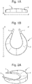
- the most favourable shape for the body 3 of the bearing 1 is a substantially horseshoe-shaped annular section (in the horizontal plane), as shown in Figure 2A .
- the bearing 1 is configured to partially or completely replace the meniscus in the knee, and to provide the support and shock absorption otherwise provided by the meniscus.
- the bearing 1 is configured to provide a concave surface into which the bottom of the femur (or femur replacing portion of a prosthetic) can sit.
- the bearing 1 may have a partially circumferential portion which is thicker than a central portion of the bearing 1 in order to provide the concave surface, as shown in Figure 2A . That is, in the sagittal and coronal planes, the cross section of the bearing 1 forms a u-shaped curve.
- the bearing could be configured for use in, for example, an ankle prosthesis, in which case the bearing would take a different anatomical shape.
- the central portion of the bearing 1 may be formed from a solid element of the same material as the circumferential portion, or a different material, but having a thinner cross section (as shown in Figure 2A ).
- the central portion may be formed from a web of the same material as the circumferential portion (or a different material), rather than a solid element.
- the circumferential portion can provide the bulk of the support for the femur (or femur replacing portion of a prosthetic).
- the central portion solid element or web can be configured to simply provide support for the circumferential portion, holding the circumferential portion in the correct shape. If the support for the circumferential portion is not necessary, the central portion can be omitted, leaving a gap in the centre of the bearing 1.
- the bearing 1 may be configured such that the central portion provides substantial support directly for the femur (or femur replacing portion of a prosthetic).
- the base section of the bearing 1 is shaped so as to conform to the top surface of all or part of the tibia (or tibia replacing portion of a prosthetic).
- the top section of the tibia (or tibia replacing portion of a prosthetic) is typically substantially flat in the transverse plane, so the corresponding base surface of the bearing 1 is then also configured to present a substantially flat surface.
- the base surface may be configured to present a different corresponding shape as required.
- the outer side portions of the bearing 1 parallel to the vertical axis are typically configured to be flat when not under load, such that the bearing 1 presents a substantially constant cross section around the outer portion parallel to the horizontal plane. This is illustrated in Figures 1A and 2A .
- the bearing 1 may alternatively present a slightly convex profile, such that the radius of the bearing 1 increases and then decreases as the vertical position varies.
- the bearing 1 can be further configured such that the thickness of the body 3 is reduced with proximity to the attachment member 7 or members 7. That is, for an annular section shaped bearing 1, the bearing 1 can be thicker around the curve of the arch section, so as to afford support in the regions where it is most required around the outer lateral and medial portions of the knee joint. This is illustrated in Figures 1A, 1B and 2A .
- the bearing 1 comprises a reinforcing element 5.
- the reinforcing element 5 may take the form of one or more elongate members, which may comprise fibres.
- the fibres may be individual cords (of single or multiple fibres), or woven into a mesh.
- the fibres may be connected together by knotting, or by moulding or adhering at connection points.
- the fibres may be adhered together using any suitable adhesive.
- the fibres may substantially encase the body 3 of the bearing 1. or may alternatively permeate the body 3 of the bearing 1 and be partially or completely encased therein,
- the reinforcing elements 5 may, alternatively, constitute a series of rigid or flexible struts or a solid rigid member within or around the body 3 of the bearing 1. Alternatively, one or more sheets of woven fibres could be used.
- the reinforcing element 5 may have a higher average modulus than the average modulus of the body 3 of the bearing 1.
- the reinforcing elements 5 may form an attachment member 7, or a plurality of attachment members 7.
- the reinforcing elements 5 are formed from a fibre or a plurality of fibres
- the attachment members 7 are the sections of the fibres which protrude from the body 3 of the bearing 1.
- the protruding sections of the fibre or fibres which form an attachment member 7 may be the ends of the fibres, or the fibre may be looped so as to re-enter the body 3 of the bearing 1 with the attachment member 7 or attachment members 7 formed by the fibre loop.
- the fibres may be linked together to form a material clip 9, which acts as the attachment member 7. by knotting, moulding or adhering.
- the material clip 9 may also be encased within a further material, for example a high modulus polymer or metal.
- an attachment member 7 may protrude from both ends of the 'arms' of the horseshoe and be linked in the middle to form a loop.
- one or more attachment members 7 may protrude from either or both arms of the horseshoe as shown in Figures 1B, 2A and 2B .
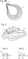
- the attachment member 7 may be configured to connect to the tibial wall (of either the tibia or a tibia replacing portion of a prosthetic), as shown in Figure 3 , where the attachment member connects to the tibia replacing portion of a prosthesis 11.
- the attachment member 7 may also or alternatively be configured to be tethered anteriorly and/or posteriorly to soft tissue via suturing of the reinforcing fibres or moulded members or by the use of bone or tethering anchors.
- the bearing 1 element may be partially held in position by raised sections on either or both of the femur and tibia (or femur and tibia replacing portions of prosthetics).
- the ridges may be created by adding additional material to the bone or prosthesis 11, or by removing sections of the bone or prosthesis 11 to leave a raised section.
- a prosthesis 11 may be used which is specifically configured to connect to the bearing 1, in particular, to the attachment member 7 or members 7.
- a prosthesis 11 may be used which has a clip or slot 9 which corresponds to the attachment member 7 or members 7 of the bearing 1 and which is therefore designed to provide a reliable connection between the bearing 1 and the prosthesis 11, as shown in Figure 3 .
- the bearing 1 may be configured to be connected directly to another bearing 1.
- a bearing 1 may be used to cushion the joint between the medial condyles of the femur and the tibia, and a further bearing 1 may be used to cushion the joint between the lateral condyles of the femur and the tibia.
- the condyles of the femur and the tibia may be fully or partially replaced by appropriate prostheses.
- the bearings may then be configured with appropriate connectors so as to connect directly to one another.
- the bearings can mutually support one another, reducing the possibility of either bearing 1 becoming dislodged.
- a larger bearing which cushions the joint area between the medial and lateral condyles of the femur and the tibia could be used.
- the clips 9 may attach onto the anterior edge of the tibial tray wall or through openings in, or on the sides of, the walls.
- the bearing 1 may also be attached to the centre of the tibial wall of the tibia (or tibia replacing portion of a prosthetic) for example by use of a bone or tethering anchor or a fibre loop/moulded member.
- the fibres may be moulded into a higher modulus material clip 9 that attaches to the tibial wall or is tethered anteriorly and/or posteriorly to soft tissue via suturing of the reinforcing fibres or moulded members or by the use of bone or tethering anchors.
- the bearing 1 may be attached to the femur, tibia, soft tissue or prosthesis 11, or any combination of these elements.
- the components of the bearing 1 must all be suitable for implantation in a living body.
- the body 3 of the bearing 1 may be manufactured from a flexible polymeric material such as low modulus polyurethane or polycarbonate urethane or hydrogel that may be reinforced with circumferential fibres to control the deformation and to minimise creep.
- a flexible polymeric material such as low modulus polyurethane or polycarbonate urethane or hydrogel that may be reinforced with circumferential fibres to control the deformation and to minimise creep.
- Other materials such as, but not limited to, high density polyethylene (HDPE), ultra-high-molecular-weight polyethylene (UHMWPE), polyether ether ketone (PEEK), carbon-fibre reinforced polyether ether ketone (CFR-PEEK), other polyaryletherketones (PAEK), other carbon-fibre reinforced polyaryletherketones (CFR-PAEK) or higher modulus polyurethanes may also be used.
- the core of the bearing 1 may incorporate one or more polymer(s) that have different moduli to modify its deformation behaviour.
- the bearing 1 may also be constructed from a series of layers of material, either alternating layers or layers where each material is used once. The layers may be stacked along one or more of the vertical, sagittal and coronal axes, or may form concentric layers.
- the attachment members 7 and clips 9 may be manufactured from implantable polymers.
- the implantable polymers have a Young's modulus (E) of 300MPa or greater.
- the implantable polymers have a Young's modulus of 600MPa or greater.
- None limiting examples of such implantable polymers are high density polyethylene (HOPE), ultra-high-molecular-weight polyethylene (UHMWPE), polyether ether ketone (PEEK), carbon-fibre reinforced polyether ether ketone (CFR-PEEK), other polyaryletherketones (PAEK), other carbon-fibre reinforced polyaryletherketones (CFR-PAEK) or higher modulus polyurethanes (e.g.
- the clips 9 may also be made from other robust materials, including metals such as steel. Depending on the materials used for the fibres the clip 9 may attach to the fibres mechanically, in any appropriate way, such as looping, via moulding or dip casting.
- the bearing 1 may be configured such that the reinforcing element 5 provides additional support for the body 3 of the bearing 1.
- the reinforcing member is typically intrinsically linked to the attachment member 7 (where the attachment member 7 is used to hold the bearing 1 in the correct position relative to the remainder of the joint)
- the remainder of the body 3 of the bearing 1 can be constructed so as to focus on allowing the best possible connection to be formed between the femur and tibia (or prosthetic) surfaces.
- the body 3 of the bearing 1 can be entirely or partially formed from a low elastic modulus material that can deform under load to conform to the femoral or tibial surface.
- An embodiment involves an anatomic femoral design.
- the bearing 1 may be configured to provide an anatomical tibial component which is also poly-radial and poly-centric.
- the invention therefore allows a bearing 1 to be used which is both anatomically fitted (so as to closely match the natural body components) and is also capable of maintaining congruency with the remaining components of the joint throughout the natural range of movement of the joint.
- This allows for prosthetic joints which are durable and which allow the user a natural range of movement.
- the joints are suitable for use by younger, more active patients as they are resistant to wear and the reinforcing member in conjunction with the attachment member 7 means that the bearings are resistant to being dislodged (e.g., by extreme impact loading).
- the bearing according to the invention is formed at least partially from a polymeric or composite material, and may comprise a lower modulus portion 105 and a higher modulus portion 103, wherein one of the modulus portions is at least partially encased within the other modulus portion.
- the lower modulus portion 105 and higher modulus portion 103 of the bearing 101 are both portions within the body 107 of the bearing.
- the lower modulus portion 105 of the body 107 is encased within the higher modulus portion 103 of the body 107 (as shown in Figure 4 . which is a cross section of a bearing 101), such that the higher modulus portion 103 of the body 107 can provide support for the lower modulus portion 105 of the body 107.
- the lower modulus portion 105 can at least partially encase the higher modulus portion 103, such that the higher modulus portion 103 provides a supporting core for the lower modulus portion 105, and the lower modulus portion 105 provides a cushioning layer on the higher modulus portion 103.
- the higher modulus portion 103 can be formed from the same compound as the lower modulus portion 105, wherein the lower modulus portion 105 is prepared in such a way as to have a lower modulus than the higher modulus portion 103.
- the lower and higher modulus portions can be formed from different compounds.
- the higher modulus portion 103 of the bearing 101 forms a tray-like structure in which the lower modulus portion 105 is configured to sit. This is illustrated in Figure 5 .
- the higher modulus portion 103 therefore provides additional bracing and support for the lower modulus portion 105.
- the tray-like structure may take any suitable shape, such as an annular or annular section shape (for example, a horseshoe shape), or an oval shape.
- the higher modulus section may provide bracing around all of the surfaces of the bearing 101, or only around some of the surfaces.
- the higher modulus section provides bracing around the base and sides of the bearing 101 but not around the top section.
- the bearing 101 may also be formed from various sections of varying moduli.
- the bearing 101 may be constructed with concentric layers of varying moduli.
- the moduli of the layers may decrease from the edge of the bearing 101 to the centre in the horizontal plane or the sagittal plane or increase from the edge to the centre, or alternate between lower and higher moduli from the edge to the centre.
- the bearing 101 is formed from portions having different moduli, this allows for a bearing 101 which is more anatomically correct while simultaneously remaining congruent with the femur and tibia (or prosthetic) surfaces.
- the central portion of the body 107 of the bearing 101 can be formed from a low elastic modulus material that can deform under load to conform to the femoral (and tibial) surface.
- the exterior portion of the bearing 101 can then provide reinforcement to the remainder of the bearing 101, effectively holding the more malleable central portion in position.
- a higher modulus central portion can be used to provide support for a lower modulus outer portion, which is thereby able to be configured so as to deform with the movement of the joint.
- An embodiment involves an anatomic femoral design. With increasing flexion the sagittal plane radius of an anatomic femoral component decreases. Full congruity in all portions is achieved either by increasing the coronal/transverse plane radius in flexion or by having the centre of curvature in flexion further medial than in extension.
- an anatomical femoral component it will be possible to have an anatomical tibial component which is also poly-radial and poly-centric.
- the invention therefore allows a bearing 101 which is both anatomically fitted (so as to closely match the natural body components) and is also capable of maintaining congruency with the remaining components of the joint throughout the natural range of movement of the joint. This allows for prosthetic joints which are durable and which allow the user a natural range of movement.
- the joints are suitable for use by younger, more active patients as they are resistant to wear and the reinforcing member in conjunction with the attachment member 7 means that the bearings 101 are resistant to being dislodged (e.g., by extreme impact loading).
- a bearing 1.101 may have reinforcing elements 5, an attachment member 7 or members 7 a lower modulus portion 105 and a higher modulus portion 103.
- the use of both reinforcing elements 5 which encase or permeate the body 3,107 of the bearing 1,101 in conjunction with a higher modulus portion 103 provides additional support for the lower modulus portion 105 of the bearing 1,101, which can therefore be configured to provide the best possible cushioning for the joint without undue concern for the support role of the bearing 1,101.
- a bearing 1,101 which combines the reinforcing element 5, attachment member 7 or members 7, a lower modulus portion 105 and a higher modulus portion 103 can therefore provide excellent cushioning and fit within a joint.
- the body 3,107 of the bearing 1,101 may be formed by first moulding (for example, injection moulding) the most central layer, typically from a thermosetting polymer as discussed. The further portions of the body 3,107 may then be over-moulded until the desired body 3,107 structure is formed.
- Bearings 1,101 having a concentric structure may also be formed using dip-coating, wherein an inner portion is formed (for example, by being moulded from a thermosetting polymer) and then outer portions are formed by dip casting onto the inner portion. Particularly good bonds between the layers may be formed if the materials used for the body 3.107 are polymers.
- inner portions of bearings 1,101 having a concentrically layered structure, or entire bearing 1,101 bodies having a uniform material structure may be formed using reaction injection moulding (RIM) or structural reaction injection moulding (SRIM).
- RIM and SRIM can produce a high density, high stiffness outer portion with a lower density inner portion.
- the inner portion may or may not be filled with a polyurethane material of different hardness to the outer portion. If SRIM is used, the materials used for the reinforcing elements (5) may also serve as the structural element for the SRIM moulded portion.
- the body 3,107 of the bearing 1,101 will be formed around pre-positioned reinforcing elements. That is, the reinforcing elements 5 are positioned in the mould, and then at least a portion of the body 3,107 of the bearing 1,101 is formed around the reinforcing elements. If further body 3,107 portions are to be added, these can then be moulded onto the body 3,107 portion having the reinforcing elements 5 attached. Alternatively, if the reinforcing elements 5 are to partially or substantially encase the bearing body 3, 107, the reinforcing elements 5 can be added after the bearing body 3,107 has been formed, or while the outer portions of the bearing body 3,107 are being formed.
- a further construction method involves forming the body 3, 107 of the bearing 1,101, and then drilling or engraving channels into which the reinforcing elements 5 are subsequently inserted or formed.
Landscapes
- Health & Medical Sciences (AREA)
- Orthopedic Medicine & Surgery (AREA)
- Engineering & Computer Science (AREA)
- Heart & Thoracic Surgery (AREA)
- Life Sciences & Earth Sciences (AREA)
- Oral & Maxillofacial Surgery (AREA)
- Transplantation (AREA)
- Biomedical Technology (AREA)
- Veterinary Medicine (AREA)
- Vascular Medicine (AREA)
- Cardiology (AREA)
- Animal Behavior & Ethology (AREA)
- General Health & Medical Sciences (AREA)
- Public Health (AREA)
- Physical Education & Sports Medicine (AREA)
- Manufacturing & Machinery (AREA)
- Prostheses (AREA)
Claims (13)
- Lager (1, 101) für eine Total- oder Teilgelenkersatzprothese (11), wobei das Lager einen Körper (3) und ein Verstärkungselement (5) aufweist, welches das Lager verstärkt und ein Befestigungselement (7) bildet, wobei das Lager zumindest teilweise aus einem polymeren oder Verbundmaterial ausgebildet ist, wobei das Lager ferner einen Teil mit niedrigem Modul (105) und einen Teil mit hohem Modul (103) umfasst, dadurch gekennzeichnet, dass der Teil mit hohem Modul (103) eine schalenartige Struktur bildet, wobei der Teil mit niedrigem Modul (105) so gestaltet ist, dass er darin sitzt, wobei die schalenartige Struktur eine Verstärkung um eine Basis und die Seiten des Lagers, jedoch nicht um einen oberen Abschnitt bereitstellt,
wobei das Befestigungselement (7) für eine Befestigung an einer Total- oder Teilgelenkersatzprothese (11) gestaltet ist. - Lager nach Anspruch 1, wobei sich das Verstärkungselement (5) teilweise in dem Körper befindet und sich aus dem Körper erstreckt, um das Befestigungselement (7) zu bilden.
- Lager nach Anspruch 1 oder 2, wobei das Verstärkungselement (5) eine Faser umfasst.
- Lager nach einem der Ansprüche 1, 2 oder 3, wobei das Verstärkungselement (5) eine Mehrzahl von Fasern umfasst.
- Lager nach Anspruch 4, wobei die Fasern so verwoben sind, um das Befestigungselement (7) zu bilden.
- Lager nach Anspruch 4, wobei die Fasern aneinander geformt oder geklebt sind, um das Befestigungselement (7) zu bilden.
- Lager nach einem der vorstehenden Ansprüche, wobei das Befestigungselement (7) eine Schlaufe umfasst.
- Lager nach einem der vorstehenden Ansprüche, wobei das Befestigungselement (7) zur Befestigung an einer Klammer (9) gestaltet ist.
- Lager nach einem der vorstehenden Ansprüche, wobei das Lager (1) eine Mehrzahl von Befestigungselemente (7) umfasst.
- Lager nach einem der Ansprüche 2 bis 9, wobei die Faser ein Gewebe bildet, das in den Körper (3) eindringt.
- Lager nach einem der Ansprüche 2 bis 9, wobei die Faser ein Gewebe bildet, das im Wesentlichen den Körper (3) umschließt.
- Lager nach Anspruch 1, das ferner zusätzliche Teile des Körpers mit unterschiedlichen Modulen umfasst.
- Lager nach Anspruch 12, wobei die Module der Teile vom Rand des Lagers zur Mitte variieren.
Applications Claiming Priority (2)
| Application Number | Priority Date | Filing Date | Title |
|---|---|---|---|
| GB1401991.3A GB2522861A (en) | 2014-02-05 | 2014-02-05 | Flexible prosthetic bearing for joint |
| PCT/GB2014/053634 WO2015118287A1 (en) | 2014-02-05 | 2014-12-08 | Flexible prosthetic bearing for joint |
Publications (2)
| Publication Number | Publication Date |
|---|---|
| EP3102155A1 EP3102155A1 (de) | 2016-12-14 |
| EP3102155B1 true EP3102155B1 (de) | 2020-01-15 |
Family
ID=50344447
Family Applications (1)
| Application Number | Title | Priority Date | Filing Date |
|---|---|---|---|
| EP14828496.1A Active EP3102155B1 (de) | 2014-02-05 | 2014-12-08 | Flexibles prothetisches lager für gelenk |
Country Status (5)
| Country | Link |
|---|---|
| US (1) | US10130482B2 (de) |
| EP (1) | EP3102155B1 (de) |
| CN (1) | CN106456333B (de) |
| GB (1) | GB2522861A (de) |
| WO (1) | WO2015118287A1 (de) |
Families Citing this family (5)
| Publication number | Priority date | Publication date | Assignee | Title |
|---|---|---|---|---|
| GB2522861A (en) | 2014-02-05 | 2015-08-12 | Biomet Uk Ltd | Flexible prosthetic bearing for joint |
| US11147677B2 (en) * | 2016-01-16 | 2021-10-19 | Philip A. Persaud | Artificial meniscus |
| EP3400912B1 (de) * | 2017-05-10 | 2019-11-20 | Howmedica Osteonics Corporation | Patientenspezifischer zusammengesetzter knieersatz |
| EP4054487A4 (de) | 2019-11-06 | 2024-02-28 | Rutgers, the State University of New Jersey | Zusammengesetztes implantat für totalmeniskusrekonstruktion |
| US12324742B2 (en) * | 2020-07-13 | 2025-06-10 | Georgia Tech Research Corporation | Orthopedic implants having circumferential and non-circumferential fibers |
Family Cites Families (14)
| Publication number | Priority date | Publication date | Assignee | Title |
|---|---|---|---|---|
| US4502161A (en) * | 1981-09-21 | 1985-03-05 | Wall W H | Prosthetic meniscus for the repair of joints |
| US5007934A (en) * | 1987-07-20 | 1991-04-16 | Regen Corporation | Prosthetic meniscus |
| US4919667A (en) | 1988-12-02 | 1990-04-24 | Stryker Corporation | Implant |
| US5171322A (en) * | 1990-02-13 | 1992-12-15 | Kenny Charles H | Stabilized meniscus prosthesis |
| US6629997B2 (en) * | 2000-03-27 | 2003-10-07 | Kevin A. Mansmann | Meniscus-type implant with hydrogel surface reinforced by three-dimensional mesh |
| US20090234453A1 (en) * | 2005-03-17 | 2009-09-17 | Active Implants Corporation | Implant devices |
| US8403985B2 (en) * | 2005-11-02 | 2013-03-26 | Zimmer, Inc. | Joint spacer implant |
| US8192491B2 (en) * | 2006-10-09 | 2012-06-05 | Active Implants Corporation | Meniscus prosthetic device |
| US20080255665A1 (en) | 2007-04-11 | 2008-10-16 | Active Implants Corporation | Anchored prosthetic meniscus device |
| US8623085B2 (en) * | 2008-06-02 | 2014-01-07 | Rutgers, The State University Of New Jersey | Bioresorbable tissue engineered fibrocartilage replacement with three-dimensional matrix of fibers |
| EP2672928A1 (de) | 2011-02-08 | 2013-12-18 | Prosthexis Pty Ltd | Meniskusprothesen und verfahren zu ihrer implantation in das menschliche kniegelenk |
| GB201109515D0 (en) | 2011-06-07 | 2011-07-20 | Imp Innovations Ltd | Implant and implant system |
| CN103007356A (zh) | 2012-12-19 | 2013-04-03 | 南京理工大学 | 带有表面耐磨层的超高分子量聚乙烯人工关节及其制备方法 |
| GB2522861A (en) | 2014-02-05 | 2015-08-12 | Biomet Uk Ltd | Flexible prosthetic bearing for joint |
-
2014
- 2014-02-05 GB GB1401991.3A patent/GB2522861A/en not_active Withdrawn
- 2014-12-08 US US15/116,447 patent/US10130482B2/en active Active
- 2014-12-08 CN CN201480077048.0A patent/CN106456333B/zh active Active
- 2014-12-08 WO PCT/GB2014/053634 patent/WO2015118287A1/en not_active Ceased
- 2014-12-08 EP EP14828496.1A patent/EP3102155B1/de active Active
Non-Patent Citations (1)
| Title |
|---|
| None * |
Also Published As
| Publication number | Publication date |
|---|---|
| EP3102155A1 (de) | 2016-12-14 |
| GB201401991D0 (en) | 2014-03-19 |
| CN106456333A (zh) | 2017-02-22 |
| WO2015118287A1 (en) | 2015-08-13 |
| GB2522861A (en) | 2015-08-12 |
| US20170007411A1 (en) | 2017-01-12 |
| CN106456333B (zh) | 2019-06-21 |
| US10130482B2 (en) | 2018-11-20 |
Similar Documents
| Publication | Publication Date | Title |
|---|---|---|
| US8403985B2 (en) | Joint spacer implant | |
| US9724202B2 (en) | Femoral component of a knee prosthesis having an angled cement pocket | |
| ES2406366T3 (es) | Prótesis con componente compuesto | |
| EP3102155B1 (de) | Flexibles prothetisches lager für gelenk | |
| US20170020679A1 (en) | Artificial Intervertebral Disc Implant Device | |
| US20130144385A1 (en) | Prosthetic menisci and method of implanting in the human knee joint | |
| US20080255665A1 (en) | Anchored prosthetic meniscus device | |
| US20080183291A1 (en) | Resurfacing the tibial plateau | |
| US20130268074A1 (en) | Prosthetic menisci and method of implanting in the human knee joint | |
| CN102440851B (zh) | 具有成角度的骨水泥腔的膝关节假体的股骨组件 | |
| JP2013537451A5 (de) | ||
| US9138322B2 (en) | Knee prosthesis having cross-compatible dome and anatomic patella components | |
| JP6430129B2 (ja) | 互換性のあるコンポーネントを有する固定軸受膝プロテーゼ | |
| JP5989490B2 (ja) | 角度付きセメントポケットを有する膝プロテーゼの脛骨コンポーネント | |
| US20220409379A1 (en) | Medical implant and anchoring system for a medical implant | |
| US8734523B2 (en) | Limited motion tibial bearing | |
| WO2025237893A1 (en) | Meniscus prosthesis for application in the lateral knee compartment | |
| CZ27453U1 (cs) | Implantát pro náhradu meziobratlového disku | |
| AU2011349045A1 (en) | Prosthetic menisci and method of implanting in the human knee joint |
Legal Events
| Date | Code | Title | Description |
|---|---|---|---|
| STAA | Information on the status of an ep patent application or granted ep patent |
Free format text: STATUS: THE INTERNATIONAL PUBLICATION HAS BEEN MADE |
|
| PUAI | Public reference made under article 153(3) epc to a published international application that has entered the european phase |
Free format text: ORIGINAL CODE: 0009012 |
|
| STAA | Information on the status of an ep patent application or granted ep patent |
Free format text: STATUS: REQUEST FOR EXAMINATION WAS MADE |
|
| 17P | Request for examination filed |
Effective date: 20160905 |
|
| AK | Designated contracting states |
Kind code of ref document: A1 Designated state(s): AL AT BE BG CH CY CZ DE DK EE ES FI FR GB GR HR HU IE IS IT LI LT LU LV MC MK MT NL NO PL PT RO RS SE SI SK SM TR |
|
| AX | Request for extension of the european patent |
Extension state: BA ME |
|
| DAX | Request for extension of the european patent (deleted) | ||
| STAA | Information on the status of an ep patent application or granted ep patent |
Free format text: STATUS: EXAMINATION IS IN PROGRESS |
|
| 17Q | First examination report despatched |
Effective date: 20181022 |
|
| GRAP | Despatch of communication of intention to grant a patent |
Free format text: ORIGINAL CODE: EPIDOSNIGR1 |
|
| STAA | Information on the status of an ep patent application or granted ep patent |
Free format text: STATUS: GRANT OF PATENT IS INTENDED |
|
| INTG | Intention to grant announced |
Effective date: 20190725 |
|
| GRAS | Grant fee paid |
Free format text: ORIGINAL CODE: EPIDOSNIGR3 |
|
| GRAA | (expected) grant |
Free format text: ORIGINAL CODE: 0009210 |
|
| STAA | Information on the status of an ep patent application or granted ep patent |
Free format text: STATUS: THE PATENT HAS BEEN GRANTED |
|
| AK | Designated contracting states |
Kind code of ref document: B1 Designated state(s): AL AT BE BG CH CY CZ DE DK EE ES FI FR GB GR HR HU IE IS IT LI LT LU LV MC MK MT NL NO PL PT RO RS SE SI SK SM TR |
|
| REG | Reference to a national code |
Ref country code: GB Ref legal event code: FG4D Ref country code: CH Ref legal event code: EP |
|
| REG | Reference to a national code |
Ref country code: CH Ref legal event code: NV Representative=s name: MICHELI AND CIE SA, CH |
|
| REG | Reference to a national code |
Ref country code: IE Ref legal event code: FG4D |
|
| REG | Reference to a national code |
Ref country code: DE Ref legal event code: R096 Ref document number: 602014060149 Country of ref document: DE |
|
| REG | Reference to a national code |
Ref country code: AT Ref legal event code: REF Ref document number: 1224504 Country of ref document: AT Kind code of ref document: T Effective date: 20200215 |
|
| REG | Reference to a national code |
Ref country code: NL Ref legal event code: MP Effective date: 20200115 |
|
| REG | Reference to a national code |
Ref country code: LT Ref legal event code: MG4D |
|
| PG25 | Lapsed in a contracting state [announced via postgrant information from national office to epo] |
Ref country code: NL Free format text: LAPSE BECAUSE OF FAILURE TO SUBMIT A TRANSLATION OF THE DESCRIPTION OR TO PAY THE FEE WITHIN THE PRESCRIBED TIME-LIMIT Effective date: 20200115 Ref country code: RS Free format text: LAPSE BECAUSE OF FAILURE TO SUBMIT A TRANSLATION OF THE DESCRIPTION OR TO PAY THE FEE WITHIN THE PRESCRIBED TIME-LIMIT Effective date: 20200115 Ref country code: FI Free format text: LAPSE BECAUSE OF FAILURE TO SUBMIT A TRANSLATION OF THE DESCRIPTION OR TO PAY THE FEE WITHIN THE PRESCRIBED TIME-LIMIT Effective date: 20200115 Ref country code: NO Free format text: LAPSE BECAUSE OF FAILURE TO SUBMIT A TRANSLATION OF THE DESCRIPTION OR TO PAY THE FEE WITHIN THE PRESCRIBED TIME-LIMIT Effective date: 20200415 Ref country code: PT Free format text: LAPSE BECAUSE OF FAILURE TO SUBMIT A TRANSLATION OF THE DESCRIPTION OR TO PAY THE FEE WITHIN THE PRESCRIBED TIME-LIMIT Effective date: 20200607 |
|
| PG25 | Lapsed in a contracting state [announced via postgrant information from national office to epo] |
Ref country code: HR Free format text: LAPSE BECAUSE OF FAILURE TO SUBMIT A TRANSLATION OF THE DESCRIPTION OR TO PAY THE FEE WITHIN THE PRESCRIBED TIME-LIMIT Effective date: 20200115 Ref country code: GR Free format text: LAPSE BECAUSE OF FAILURE TO SUBMIT A TRANSLATION OF THE DESCRIPTION OR TO PAY THE FEE WITHIN THE PRESCRIBED TIME-LIMIT Effective date: 20200416 Ref country code: SE Free format text: LAPSE BECAUSE OF FAILURE TO SUBMIT A TRANSLATION OF THE DESCRIPTION OR TO PAY THE FEE WITHIN THE PRESCRIBED TIME-LIMIT Effective date: 20200115 Ref country code: LV Free format text: LAPSE BECAUSE OF FAILURE TO SUBMIT A TRANSLATION OF THE DESCRIPTION OR TO PAY THE FEE WITHIN THE PRESCRIBED TIME-LIMIT Effective date: 20200115 Ref country code: IS Free format text: LAPSE BECAUSE OF FAILURE TO SUBMIT A TRANSLATION OF THE DESCRIPTION OR TO PAY THE FEE WITHIN THE PRESCRIBED TIME-LIMIT Effective date: 20200515 Ref country code: BG Free format text: LAPSE BECAUSE OF FAILURE TO SUBMIT A TRANSLATION OF THE DESCRIPTION OR TO PAY THE FEE WITHIN THE PRESCRIBED TIME-LIMIT Effective date: 20200415 |
|
| REG | Reference to a national code |
Ref country code: DE Ref legal event code: R097 Ref document number: 602014060149 Country of ref document: DE |
|
| REG | Reference to a national code |
Ref country code: DE Ref legal event code: R082 Ref document number: 602014060149 Country of ref document: DE Representative=s name: VENNER SHIPLEY GERMANY LLP, DE Ref country code: DE Ref legal event code: R082 Ref document number: 602014060149 Country of ref document: DE Representative=s name: VENNER SHIPLEY LLP, DE |
|
| PG25 | Lapsed in a contracting state [announced via postgrant information from national office to epo] |
Ref country code: CZ Free format text: LAPSE BECAUSE OF FAILURE TO SUBMIT A TRANSLATION OF THE DESCRIPTION OR TO PAY THE FEE WITHIN THE PRESCRIBED TIME-LIMIT Effective date: 20200115 Ref country code: RO Free format text: LAPSE BECAUSE OF FAILURE TO SUBMIT A TRANSLATION OF THE DESCRIPTION OR TO PAY THE FEE WITHIN THE PRESCRIBED TIME-LIMIT Effective date: 20200115 Ref country code: ES Free format text: LAPSE BECAUSE OF FAILURE TO SUBMIT A TRANSLATION OF THE DESCRIPTION OR TO PAY THE FEE WITHIN THE PRESCRIBED TIME-LIMIT Effective date: 20200115 Ref country code: EE Free format text: LAPSE BECAUSE OF FAILURE TO SUBMIT A TRANSLATION OF THE DESCRIPTION OR TO PAY THE FEE WITHIN THE PRESCRIBED TIME-LIMIT Effective date: 20200115 Ref country code: SM Free format text: LAPSE BECAUSE OF FAILURE TO SUBMIT A TRANSLATION OF THE DESCRIPTION OR TO PAY THE FEE WITHIN THE PRESCRIBED TIME-LIMIT Effective date: 20200115 Ref country code: DK Free format text: LAPSE BECAUSE OF FAILURE TO SUBMIT A TRANSLATION OF THE DESCRIPTION OR TO PAY THE FEE WITHIN THE PRESCRIBED TIME-LIMIT Effective date: 20200115 Ref country code: LT Free format text: LAPSE BECAUSE OF FAILURE TO SUBMIT A TRANSLATION OF THE DESCRIPTION OR TO PAY THE FEE WITHIN THE PRESCRIBED TIME-LIMIT Effective date: 20200115 Ref country code: SK Free format text: LAPSE BECAUSE OF FAILURE TO SUBMIT A TRANSLATION OF THE DESCRIPTION OR TO PAY THE FEE WITHIN THE PRESCRIBED TIME-LIMIT Effective date: 20200115 |
|
| REG | Reference to a national code |
Ref country code: AT Ref legal event code: MK05 Ref document number: 1224504 Country of ref document: AT Kind code of ref document: T Effective date: 20200115 |
|
| PLBE | No opposition filed within time limit |
Free format text: ORIGINAL CODE: 0009261 |
|
| STAA | Information on the status of an ep patent application or granted ep patent |
Free format text: STATUS: NO OPPOSITION FILED WITHIN TIME LIMIT |
|
| 26N | No opposition filed |
Effective date: 20201016 |
|
| PG25 | Lapsed in a contracting state [announced via postgrant information from national office to epo] |
Ref country code: IT Free format text: LAPSE BECAUSE OF FAILURE TO SUBMIT A TRANSLATION OF THE DESCRIPTION OR TO PAY THE FEE WITHIN THE PRESCRIBED TIME-LIMIT Effective date: 20200115 Ref country code: AT Free format text: LAPSE BECAUSE OF FAILURE TO SUBMIT A TRANSLATION OF THE DESCRIPTION OR TO PAY THE FEE WITHIN THE PRESCRIBED TIME-LIMIT Effective date: 20200115 |
|
| PG25 | Lapsed in a contracting state [announced via postgrant information from national office to epo] |
Ref country code: SI Free format text: LAPSE BECAUSE OF FAILURE TO SUBMIT A TRANSLATION OF THE DESCRIPTION OR TO PAY THE FEE WITHIN THE PRESCRIBED TIME-LIMIT Effective date: 20200115 Ref country code: PL Free format text: LAPSE BECAUSE OF FAILURE TO SUBMIT A TRANSLATION OF THE DESCRIPTION OR TO PAY THE FEE WITHIN THE PRESCRIBED TIME-LIMIT Effective date: 20200115 |
|
| PG25 | Lapsed in a contracting state [announced via postgrant information from national office to epo] |
Ref country code: MC Free format text: LAPSE BECAUSE OF FAILURE TO SUBMIT A TRANSLATION OF THE DESCRIPTION OR TO PAY THE FEE WITHIN THE PRESCRIBED TIME-LIMIT Effective date: 20200115 |
|
| REG | Reference to a national code |
Ref country code: BE Ref legal event code: MM Effective date: 20201231 |
|
| PG25 | Lapsed in a contracting state [announced via postgrant information from national office to epo] |
Ref country code: LU Free format text: LAPSE BECAUSE OF NON-PAYMENT OF DUE FEES Effective date: 20201208 Ref country code: IE Free format text: LAPSE BECAUSE OF NON-PAYMENT OF DUE FEES Effective date: 20201208 |
|
| PG25 | Lapsed in a contracting state [announced via postgrant information from national office to epo] |
Ref country code: TR Free format text: LAPSE BECAUSE OF FAILURE TO SUBMIT A TRANSLATION OF THE DESCRIPTION OR TO PAY THE FEE WITHIN THE PRESCRIBED TIME-LIMIT Effective date: 20200115 Ref country code: MT Free format text: LAPSE BECAUSE OF FAILURE TO SUBMIT A TRANSLATION OF THE DESCRIPTION OR TO PAY THE FEE WITHIN THE PRESCRIBED TIME-LIMIT Effective date: 20200115 Ref country code: CY Free format text: LAPSE BECAUSE OF FAILURE TO SUBMIT A TRANSLATION OF THE DESCRIPTION OR TO PAY THE FEE WITHIN THE PRESCRIBED TIME-LIMIT Effective date: 20200115 |
|
| PG25 | Lapsed in a contracting state [announced via postgrant information from national office to epo] |
Ref country code: MK Free format text: LAPSE BECAUSE OF FAILURE TO SUBMIT A TRANSLATION OF THE DESCRIPTION OR TO PAY THE FEE WITHIN THE PRESCRIBED TIME-LIMIT Effective date: 20200115 Ref country code: AL Free format text: LAPSE BECAUSE OF FAILURE TO SUBMIT A TRANSLATION OF THE DESCRIPTION OR TO PAY THE FEE WITHIN THE PRESCRIBED TIME-LIMIT Effective date: 20200115 |
|
| PG25 | Lapsed in a contracting state [announced via postgrant information from national office to epo] |
Ref country code: BE Free format text: LAPSE BECAUSE OF NON-PAYMENT OF DUE FEES Effective date: 20201231 |
|
| P01 | Opt-out of the competence of the unified patent court (upc) registered |
Effective date: 20230526 |
|
| PGFP | Annual fee paid to national office [announced via postgrant information from national office to epo] |
Ref country code: CH Payment date: 20250101 Year of fee payment: 11 |
|
| REG | Reference to a national code |
Ref country code: CH Ref legal event code: U11 Free format text: ST27 STATUS EVENT CODE: U-0-0-U10-U11 (AS PROVIDED BY THE NATIONAL OFFICE) Effective date: 20260101 |
|
| PGFP | Annual fee paid to national office [announced via postgrant information from national office to epo] |
Ref country code: DE Payment date: 20251112 Year of fee payment: 12 |
|
| PGFP | Annual fee paid to national office [announced via postgrant information from national office to epo] |
Ref country code: GB Payment date: 20251114 Year of fee payment: 12 |
|
| PGFP | Annual fee paid to national office [announced via postgrant information from national office to epo] |
Ref country code: FR Payment date: 20251112 Year of fee payment: 12 |