EP3100983B1 - Ballast water treatment system by using nadcc - Google Patents
Ballast water treatment system by using nadcc Download PDFInfo
- Publication number
- EP3100983B1 EP3100983B1 EP16172331.7A EP16172331A EP3100983B1 EP 3100983 B1 EP3100983 B1 EP 3100983B1 EP 16172331 A EP16172331 A EP 16172331A EP 3100983 B1 EP3100983 B1 EP 3100983B1
- Authority
- EP
- European Patent Office
- Prior art keywords
- nadcc
- valve
- inlet
- auto
- dissolution tank
- Prior art date
- Legal status (The legal status is an assumption and is not a legal conclusion. Google has not performed a legal analysis and makes no representation as to the accuracy of the status listed.)
- Active
Links
- XLYOFNOQVPJJNP-UHFFFAOYSA-N water Substances O XLYOFNOQVPJJNP-UHFFFAOYSA-N 0.000 title claims description 61
- 238000004090 dissolution Methods 0.000 claims description 33
- 239000007864 aqueous solution Substances 0.000 claims description 18
- 239000013505 freshwater Substances 0.000 claims description 17
- 239000008187 granular material Substances 0.000 claims description 13
- 238000001816 cooling Methods 0.000 claims description 3
- CEJLBZWIKQJOAT-UHFFFAOYSA-N dichloroisocyanuric acid Chemical compound ClN1C(=O)NC(=O)N(Cl)C1=O CEJLBZWIKQJOAT-UHFFFAOYSA-N 0.000 claims 6
- MSFGZHUJTJBYFA-UHFFFAOYSA-M sodium dichloroisocyanurate Chemical compound [Na+].ClN1C(=O)[N-]C(=O)N(Cl)C1=O MSFGZHUJTJBYFA-UHFFFAOYSA-M 0.000 description 85
- 239000007800 oxidant agent Substances 0.000 description 16
- 230000001590 oxidative effect Effects 0.000 description 16
- 238000000034 method Methods 0.000 description 8
- 238000002347 injection Methods 0.000 description 7
- 239000007924 injection Substances 0.000 description 7
- 230000001954 sterilising effect Effects 0.000 description 6
- 238000010586 diagram Methods 0.000 description 4
- WQYVRQLZKVEZGA-UHFFFAOYSA-N hypochlorite Chemical compound Cl[O-] WQYVRQLZKVEZGA-UHFFFAOYSA-N 0.000 description 4
- 244000052769 pathogen Species 0.000 description 4
- 230000001717 pathogenic effect Effects 0.000 description 4
- 239000013535 sea water Substances 0.000 description 4
- 239000000243 solution Substances 0.000 description 4
- 238000013019 agitation Methods 0.000 description 3
- 239000000428 dust Substances 0.000 description 3
- 238000004659 sterilization and disinfection Methods 0.000 description 3
- FAPWRFPIFSIZLT-UHFFFAOYSA-M Sodium chloride Chemical compound [Na+].[Cl-] FAPWRFPIFSIZLT-UHFFFAOYSA-M 0.000 description 2
- 239000013543 active substance Substances 0.000 description 2
- 239000003651 drinking water Substances 0.000 description 2
- 230000002070 germicidal effect Effects 0.000 description 2
- 244000005700 microbiome Species 0.000 description 2
- SUKJFIGYRHOWBL-UHFFFAOYSA-N sodium hypochlorite Chemical compound [Na+].Cl[O-] SUKJFIGYRHOWBL-UHFFFAOYSA-N 0.000 description 2
- 239000007787 solid Substances 0.000 description 2
- 241000894007 species Species 0.000 description 2
- 239000000126 substance Substances 0.000 description 2
- 206010008631 Cholera Diseases 0.000 description 1
- 239000005708 Sodium hypochlorite Substances 0.000 description 1
- 244000052616 bacterial pathogen Species 0.000 description 1
- 235000012206 bottled water Nutrition 0.000 description 1
- 230000015556 catabolic process Effects 0.000 description 1
- 239000003795 chemical substances by application Substances 0.000 description 1
- 239000002131 composite material Substances 0.000 description 1
- 238000006731 degradation reaction Methods 0.000 description 1
- 238000007599 discharging Methods 0.000 description 1
- 201000010099 disease Diseases 0.000 description 1
- 208000037265 diseases, disorders, signs and symptoms Diseases 0.000 description 1
- 235000020188 drinking water Nutrition 0.000 description 1
- 230000000694 effects Effects 0.000 description 1
- 238000001914 filtration Methods 0.000 description 1
- 239000007788 liquid Substances 0.000 description 1
- 238000012423 maintenance Methods 0.000 description 1
- 230000037125 natural defense Effects 0.000 description 1
- 239000000843 powder Substances 0.000 description 1
- 230000001681 protective effect Effects 0.000 description 1
- 150000003839 salts Chemical class 0.000 description 1
- 238000007789 sealing Methods 0.000 description 1
- 239000010865 sewage Substances 0.000 description 1
- 239000011780 sodium chloride Substances 0.000 description 1
- 239000013589 supplement Substances 0.000 description 1
- 230000001502 supplementing effect Effects 0.000 description 1
- 231100000331 toxic Toxicity 0.000 description 1
- 230000002588 toxic effect Effects 0.000 description 1
- 238000004065 wastewater treatment Methods 0.000 description 1
Images

Classifications
-
- B—PERFORMING OPERATIONS; TRANSPORTING
- B63—SHIPS OR OTHER WATERBORNE VESSELS; RELATED EQUIPMENT
- B63J—AUXILIARIES ON VESSELS
- B63J4/00—Arrangements of installations for treating ballast water, waste water, sewage, sludge, or refuse, or for preventing environmental pollution not otherwise provided for
- B63J4/002—Arrangements of installations for treating ballast water, waste water, sewage, sludge, or refuse, or for preventing environmental pollution not otherwise provided for for treating ballast water
-
- C—CHEMISTRY; METALLURGY
- C02—TREATMENT OF WATER, WASTE WATER, SEWAGE, OR SLUDGE
- C02F—TREATMENT OF WATER, WASTE WATER, SEWAGE, OR SLUDGE
- C02F1/00—Treatment of water, waste water, or sewage
- C02F1/68—Treatment of water, waste water, or sewage by addition of specified substances, e.g. trace elements, for ameliorating potable water
- C02F1/685—Devices for dosing the additives
- C02F1/686—Devices for dosing liquid additives
-
- B—PERFORMING OPERATIONS; TRANSPORTING
- B01—PHYSICAL OR CHEMICAL PROCESSES OR APPARATUS IN GENERAL
- B01F—MIXING, e.g. DISSOLVING, EMULSIFYING OR DISPERSING
- B01F27/00—Mixers with rotary stirring devices in fixed receptacles; Kneaders
- B01F27/05—Stirrers
- B01F27/11—Stirrers characterised by the configuration of the stirrers
- B01F27/112—Stirrers characterised by the configuration of the stirrers with arms, paddles, vanes or blades
-
- B—PERFORMING OPERATIONS; TRANSPORTING
- B01—PHYSICAL OR CHEMICAL PROCESSES OR APPARATUS IN GENERAL
- B01F—MIXING, e.g. DISSOLVING, EMULSIFYING OR DISPERSING
- B01F21/00—Dissolving
- B01F21/10—Dissolving using driven stirrers
-
- B—PERFORMING OPERATIONS; TRANSPORTING
- B01—PHYSICAL OR CHEMICAL PROCESSES OR APPARATUS IN GENERAL
- B01F—MIXING, e.g. DISSOLVING, EMULSIFYING OR DISPERSING
- B01F21/00—Dissolving
- B01F21/20—Dissolving using flow mixing
- B01F21/22—Dissolving using flow mixing using additional holders in conduits, containers or pools for keeping the solid material in place, e.g. supports or receptacles
-
- B—PERFORMING OPERATIONS; TRANSPORTING
- B01—PHYSICAL OR CHEMICAL PROCESSES OR APPARATUS IN GENERAL
- B01F—MIXING, e.g. DISSOLVING, EMULSIFYING OR DISPERSING
- B01F21/00—Dissolving
- B01F21/30—Workflow diagrams or layout of plants, e.g. flow charts; Details of workflow diagrams or layout of plants, e.g. controlling means
-
- B—PERFORMING OPERATIONS; TRANSPORTING
- B01—PHYSICAL OR CHEMICAL PROCESSES OR APPARATUS IN GENERAL
- B01F—MIXING, e.g. DISSOLVING, EMULSIFYING OR DISPERSING
- B01F21/00—Dissolving
- B01F21/40—Dissolving characterised by the state of the material being dissolved
- B01F21/402—Dissolving characterised by the state of the material being dissolved characterised by the configuration, form or shape of the solid material, e.g. in the form of tablets or blocks
-
- B—PERFORMING OPERATIONS; TRANSPORTING
- B01—PHYSICAL OR CHEMICAL PROCESSES OR APPARATUS IN GENERAL
- B01F—MIXING, e.g. DISSOLVING, EMULSIFYING OR DISPERSING
- B01F25/00—Flow mixers; Mixers for falling materials, e.g. solid particles
- B01F25/30—Injector mixers
- B01F25/31—Injector mixers in conduits or tubes through which the main component flows
- B01F25/316—Injector mixers in conduits or tubes through which the main component flows with containers for additional components fixed to the conduit
-
- B—PERFORMING OPERATIONS; TRANSPORTING
- B01—PHYSICAL OR CHEMICAL PROCESSES OR APPARATUS IN GENERAL
- B01F—MIXING, e.g. DISSOLVING, EMULSIFYING OR DISPERSING
- B01F27/00—Mixers with rotary stirring devices in fixed receptacles; Kneaders
- B01F27/80—Mixers with rotary stirring devices in fixed receptacles; Kneaders with stirrers rotating about a substantially vertical axis
- B01F27/90—Mixers with rotary stirring devices in fixed receptacles; Kneaders with stirrers rotating about a substantially vertical axis with paddles or arms
-
- B—PERFORMING OPERATIONS; TRANSPORTING
- B01—PHYSICAL OR CHEMICAL PROCESSES OR APPARATUS IN GENERAL
- B01F—MIXING, e.g. DISSOLVING, EMULSIFYING OR DISPERSING
- B01F35/00—Accessories for mixers; Auxiliary operations or auxiliary devices; Parts or details of general application
- B01F35/20—Measuring; Control or regulation
- B01F35/21—Measuring
- B01F35/213—Measuring of the properties of the mixtures, e.g. temperature, density or colour
-
- B—PERFORMING OPERATIONS; TRANSPORTING
- B01—PHYSICAL OR CHEMICAL PROCESSES OR APPARATUS IN GENERAL
- B01F—MIXING, e.g. DISSOLVING, EMULSIFYING OR DISPERSING
- B01F35/00—Accessories for mixers; Auxiliary operations or auxiliary devices; Parts or details of general application
- B01F35/71—Feed mechanisms
- B01F35/717—Feed mechanisms characterised by the means for feeding the components to the mixer
- B01F35/71805—Feed mechanisms characterised by the means for feeding the components to the mixer using valves, gates, orifices or openings
-
- B—PERFORMING OPERATIONS; TRANSPORTING
- B01—PHYSICAL OR CHEMICAL PROCESSES OR APPARATUS IN GENERAL
- B01F—MIXING, e.g. DISSOLVING, EMULSIFYING OR DISPERSING
- B01F35/00—Accessories for mixers; Auxiliary operations or auxiliary devices; Parts or details of general application
- B01F35/75—Discharge mechanisms
- B01F35/754—Discharge mechanisms characterised by the means for discharging the components from the mixer
- B01F35/7547—Discharge mechanisms characterised by the means for discharging the components from the mixer using valves, gates, orifices or openings
-
- C—CHEMISTRY; METALLURGY
- C02—TREATMENT OF WATER, WASTE WATER, SEWAGE, OR SLUDGE
- C02F—TREATMENT OF WATER, WASTE WATER, SEWAGE, OR SLUDGE
- C02F1/00—Treatment of water, waste water, or sewage
- C02F1/72—Treatment of water, waste water, or sewage by oxidation
- C02F1/76—Treatment of water, waste water, or sewage by oxidation with halogens or compounds of halogens
-
- B—PERFORMING OPERATIONS; TRANSPORTING
- B01—PHYSICAL OR CHEMICAL PROCESSES OR APPARATUS IN GENERAL
- B01F—MIXING, e.g. DISSOLVING, EMULSIFYING OR DISPERSING
- B01F2101/00—Mixing characterised by the nature of the mixed materials or by the application field
- B01F2101/48—Mixing water in water-taps with other ingredients, e.g. air, detergents or disinfectants
-
- C—CHEMISTRY; METALLURGY
- C02—TREATMENT OF WATER, WASTE WATER, SEWAGE, OR SLUDGE
- C02F—TREATMENT OF WATER, WASTE WATER, SEWAGE, OR SLUDGE
- C02F1/00—Treatment of water, waste water, or sewage
- C02F1/68—Treatment of water, waste water, or sewage by addition of specified substances, e.g. trace elements, for ameliorating potable water
- C02F1/685—Devices for dosing the additives
- C02F1/688—Devices in which the water progressively dissolves a solid compound
-
- C—CHEMISTRY; METALLURGY
- C02—TREATMENT OF WATER, WASTE WATER, SEWAGE, OR SLUDGE
- C02F—TREATMENT OF WATER, WASTE WATER, SEWAGE, OR SLUDGE
- C02F2103/00—Nature of the water, waste water, sewage or sludge to be treated
- C02F2103/008—Originating from marine vessels, ships and boats, e.g. bilge water or ballast water
-
- C—CHEMISTRY; METALLURGY
- C02—TREATMENT OF WATER, WASTE WATER, SEWAGE, OR SLUDGE
- C02F—TREATMENT OF WATER, WASTE WATER, SEWAGE, OR SLUDGE
- C02F2209/00—Controlling or monitoring parameters in water treatment
- C02F2209/05—Conductivity or salinity
-
- C—CHEMISTRY; METALLURGY
- C02—TREATMENT OF WATER, WASTE WATER, SEWAGE, OR SLUDGE
- C02F—TREATMENT OF WATER, WASTE WATER, SEWAGE, OR SLUDGE
- C02F2209/00—Controlling or monitoring parameters in water treatment
- C02F2209/42—Liquid level
-
- C—CHEMISTRY; METALLURGY
- C02—TREATMENT OF WATER, WASTE WATER, SEWAGE, OR SLUDGE
- C02F—TREATMENT OF WATER, WASTE WATER, SEWAGE, OR SLUDGE
- C02F2303/00—Specific treatment goals
- C02F2303/04—Disinfection
Definitions
- the present disclosure relates to a ballast water treatment system by using Sodium dichloroisocyanurate (NaDCC), and more particularly, to a ballast water treatment system by using Sodium dichloroisocyanurate (NaDCC) which enables to safely handle Sodium dichloroisocyanurate (NaDCC) of granule type.
- NaDCC Sodium dichloroisocyanurate
- Document WO 2007/122625 A2 discloses a water treatment apparatus suitable for ballast water treatment comprising a cartridge containing Sodium dichloroisocyanurate and a dissolution tank equipped with an agitator to agitate the Sodium dichloroisocyanurate.
- Document US 2010/0006513 A1 discloses a device, system and method for treating water, in which a water treating agent is prepared and dispensed to an untreated drinking water source in discrete and consecutive control volumes enabling untreated water in the untreated water source to be treated thereby to provide potable water.
- ballast water should be introduced into a ship so as to implement a balance of the ship, a safety, and an improved ship maneuverability, so that it is possible to leave on a voyage in a ballast condition.
- the ballast water is filled from a harbor and is transported to a new harbor of other place where the ballast water is discharged.
- the release of marine organism and pathogen contained in the ballast water carried from distant location may be dangerous to both people and animal in the new harbor as well as harmful to a new environment.
- non-natural marine life When non-natural marine life is introduced into a new ecosystem, it may cause a devastating effect to natural flora and fauna which may not have a natural defense system against new species.
- harmful bacterial pathogen such as cholera
- Such a pathogen may be proliferated in a ballast tank over time, so that disease may break out in an area where the pathogen is released.
- a risk posed by such marine life and pathogen may be controlled by killing the above species existing in the ballast water.
- An electrolytic method that treats ballast water by using sodium hypochlorite generated by electrolyzing sea water is widely used for the method for killing organisms.
- the treating of the ballast water by using the above mentioned electrolytic method should convert NaCl contained in seawater into NaClO, this treating of the ballast water is easy in a sea water area, but when a ship sails in a freshwater area such as river (in particular, in an area where salt concentration is 0.5 g/ kg water (0.5psu) or less), it is impossible to use the electrolytic method.
- Sodium dichloroisocyanurate (hereinafter referred to as 'NaDCC') is cheap and has a strong sterilizing power among the germicide, it is widely used in a sterilization treatment.
- NaDCC should be treated very carefully, as it causes a severe stimulus to the eyes, and is toxic if breathed in, and is harmful if swallowed. Since an aqueous solution type NaDCC have a large volume and is degraded according to temperature, a place where it can be used is limited and it is hard to treat a large amount for proper storage.
- a granule type NaDCC has difficulty in handling because it is easy to be scattered in the form of dust. Therefore, when supplementing the granule type NaDCC, an expert who is equipped with safety equipment should perform the operation, so that operation time becomes longer. Further, since the NaDCC dust is liable to be scattered, a separate ventilator is needed such that the overall system becomes complex and larger.
- the present disclosure has been made in view of the above problems, and provides a ballast water treatment apparatus by using NaDCC which enables to handle easily a granule type NaDCC.
- a ballast water treatment apparatus includes the features of independent claim 1.
- a plurality of the cartridges are connected in parallel.
- the cartridge comprises a transparent window in a side to determine whether the equipped sodium dichloroisocyanurate is used.
- a capacity of the cartridge and the dissolution tank is determined to achieve a solubility 4%, 8% or 12% of the sodium dichloroisocyanurate.
- the inlet valve and the exhaust valve are manual valves.
- An auto-inlet valve is installed in an inlet side of the inlet valve, and an auto-discharge valve is installed in a discharge side of the exhaust valve.
- the dissolution tank is provided with a cooling unit installed in an outside.
- the dissolution tank is provided with a level sensor configured to measure a water level, and the controller is configured to open or close the auto-inlet valve and the auto-discharge valve depending on a water level signal transmitted from the level sensor.
- FIG. 1 is a diagram illustrating a configuration of a ballast water treatment apparatus by using NaDCC according to an embodiment of the present disclosure
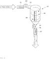
- FIG. 2 is a diagram illustrating a NaDCC injection apparatus provided in a ballast water treatment apparatus by using NaDCC according to an embodiment of the present disclosure.
- the ballast water treatment apparatus by using NaDCC may be an apparatus for treating ballast water by injecting an oxidant solution into the ballast water introduced into a ballast tank 120 along a main pipe 10 for ballast water of ship.
- the used oxidant may perform sterilization treatment for the ballast water by using a hypochlorite (HClO) which is generated by dissolving the Sodium dichloroisocyanurate (NaDCC) in water.
- HHClO hypochlorite
- NaDCC Sodium dichloroisocyanurate
- the ballast water treatment apparatus by using NaDCC may include the main pipe 10, a suction pump 13, a total residual oxidant (hereinafter referred to as 'TRO') sensor 17, a fresh water supply pipe 20, cartridges 60 and 80 equipped with NaDCC and a dissolution tank 91.
- 'TRO' total residual oxidant
- the suction pump 13 may be a pump for introducing the ballast water to the ballast tank 120 through the main pipe 10 to store the ballast water in the ballast tank 120.
- the ballast water treatment apparatus may be provided with a filter 11 to filter a foreign object or a large-sized microorganism included in the ballast water introduced into a front-side of the suction pump 13. If necessary, the filter 11 may be omitted.
- a flow meter 14 may be installed on the discharge side of the suction pump 13 to measure the flow rate of the water introduced through the suction pump 13.
- the TRO sensor 17 may be installed on the main pipe 10 after an oxidant injection pipe 40 is joined with the main pipe 10 for ballast water so as to measure the TRO concentration of the ballast water after the oxidant is injected.
- the fresh water supply pipe 20 may be installed to connect a fresh water supply unit (not shown) with the NaDCC cartridges 60 and 80 so that the fresh water may be introduced into the NaDCC cartridges 60 and 80.
- the NaDCC cartridge 60 is provided with a granule type NaDCC and, as shown in FIG. 2 , may include an inlet fitting unit 61 which is connect with the fresh water supply pipe 20 so that fresh water may be introduced and be discharged after being mixed with NaDCC, and a discharge fitting unit 67 which is connected to a dissolution tank 91 via connection pipe 30.
- the NaDCC cartridge 60 may include a body 64 having a cylindrical shape, an inlet 63 formed on the side of a top of the body 64 to guide the inflow of fresh water, and an outlet 65 of a funnel shape formed at the bottom of the body 64 to discharge aqueous solution obtained by mixing the fresh water with NaDCC.
- the NaDCC cartridge 60 may be provided with a separate injection unit to inject the granule type NaDCC, but may inject the granule type NaDCC through the above inlet 63.
- the NaDCC cartridge 60 is closed so that built-in NaDCC may not be leaked for a separate keeping or during movement to the outside for mounting and, after being mounted to a cartridge mounting unit of the ballast water treatment apparatus, is provided with an inlet valve 62 and an exhaust valve 66 which are opened to enable to accomplish the inflow of fresh water and the discharge of NaDCC aqueous solution.
- the NaDCC the cartridge 60 may be provided with a transparent window 68 on the side of the body 64 to identify amount of used built-in NaDCC of granule type to determine replacement time. At this time, gradation may be formed on the transparent window 68 to measure the stored capacity or used capacity.
- separate protective equipment may not be needed even if the NaDCC is left in the cartridge 60 because there is no dust as the NaDCC is not in a powder state but in a paste state.
- a plurality of the ballast water treatment apparatus by using NaDCC may be connected in parallel to be installed, as shown in FIG. 1 , to supply a large amount of oxidant.
- two cartridges 60 and 80 are installed in parallel in the drawing, it is also possible to provide additional cartridges in parallel when an oxidant for a larger capacity is required.
- Such a configuration may be effective in terms of maintenance because an appropriate number of cartridges can be installed to meet the needs of the ship of various sizes, and it is also possible to replace the module upon failure.
- the dissolution tank 91 may be connected by the NaDCC cartridge 60, 80 and the dissolution tank connection pipe 30 so that the NaDCC aqueous solution may be introduced.
- the dissolution tank 91 may be equipped with an agitator 99 having a blade unit 92 for agitating the NaDCC aqueous solution so that the NaDCC aqueous solution may be completely dissolved.
- a conductivity sensor 95 is installed to measure the conductivity of the dissolved NaDCC aqueous solution.
- the capacity of the cartridge 60, 80 and the dissolution tank 91 may be determined in such a manner that the solubility of NaDCC becomes 8%.
- the solubility of NaDCC is 22.7%, but, preferably, 8% when considering dissolving time and complete dissolving.
- the capacity of the dissolution tank 91 is 50L
- the capacity of cartridge 60, 80 is designed to be 4Kg.
- the capacity of the cartridge 60, 80 and the dissolution tank 91 may be determined in such a manner that the solubility becomes 4% or 12% by assigning upper and lower margins based on the solubility 8%.
- the agitator 99 may operate about 20 minutes after the dissolution tank 91 is supplemented with the NaDCC aqueous solution.
- the conductivity may increase as the NaDCC is more dissolved, and the conductivity becomes 24mS/cm2 when it is completely dissolved 8%.
- the conductivity sensor 95 it is possible to shorten the agitation time by determining whether it is fully dissolved.
- the dissolution tank 91 may be provided with a level sensor 97 to measure a water level of the NaDCC aqueous solution.
- a level sensor 97 to measure a water level of the NaDCC aqueous solution.
- auto-inlet valve 51, 71 and auto-discharge valve 59, 79 may be opened to supply fresh water into the cartridge 60, 80, and the NaDCC in the cartridge 60, 80 may be transferred to the dissolution tank 91 by the fresh water.
- the fresh water may be supplied until the level sensor 97 reaches a high level state, and, after reaching the high level state, the auto-inlet valves 51, 71 and/or the auto-discharge valve 59, 79 may be closed.
- dissolution tank 91 may be provided with an air vent 98 to introduce and discharge the NaDCC solution smoothly.
- a cooling unit may be provided in the outside to prevent degradation according to the temperature of the NaDCC aqueous solution.
- the auto-inlet valves 51, 71 may be installed in the introducing side of the inlet valve 62, 82 respectively, and the auto-discharge valves 59, 79 may be installed in the discharging side of the discharge valves 66, 86 respectively.
- the inlet valve 62, 82 and the exhaust valve 66, 86 may be configured of a manual valve.
- the inlet valve 62, 82 and the exhaust valve 66, 86 are a means for preventing the built-in NaDCC from being leaked to the outside.
- a protection film (not shown) may be provide to the inlet unit and the exhaust unit.
- the protection film (not shown) is configured to be destroyed when the cartridge is coupled to a connection pipe, it may perform a sealing function of the inlet valve and the exhaust valve of the present disclosure. However, in this case, it is disadvantages in that the cartridge cannot be recycled. Therefore, it is preferable that the built-in NaDCC is sealed by the valve.
- a dosing pump 101 may be provided between a control valve 103 and the dissolution tank 91 so that an oxidant solution 93 where the NaDCC is dissolved may be joined to the main pipe 10 through the oxidant injection pipe 40, and perform a function of controlling and injecting the oxidant solution 93 as a fixed capacity.
- a controller 110 may receive a signal from various sensors to operate a pump, or perform a function of opening and closing the valves.
- a signal relating to the level of the dissolution tank 91 may be received from the level sensor 97 to generate a control signal for opening or closing the auto-inlet valves 51, 71 and the auto-discharge valves 59, 79.
- the controller 110 may receive the TRO concentration value of the ballast water from the TRO sensor 17 to determine the amount of input of the oxidant 91, and then, adjust the rotation speed of the dosing pump 101 or the opening degree of the control valve 103, or control the dosing pump 101 and the control valve simultaneously to generate a control signal for determining the amount of input of the oxidant 91.
- the controller 110 receives conductivity information of the NaDCC aqueous solution in the dissolution tank 91 to determine whether complete dissolution is achieved based on the conductivity information, and then, generate a control signal for stopping the operation of the agitator 99 if complete dissolution is achieved.
- the cartridge 60, 80 equipped with the granule type NaDCC may be mounted in the ballast water treatment apparatus. It may be moved in the state in which the inlet valve 62, 82 and the discharge valve 66, 86 are closed before mounting, and the state of manually opening the inlet valve 62, 82 and the discharge valve 66, 86 may be maintained after mounting.
- sea water may be introduced into the inside of the ship through sea chest and transferred to the ballast tank 120 along the main pipe 10.
- fresh water may be supplied to the cartridge 60, 80 so that the NaDCC aqueous solution is introduced into the dissolution tank 91.
- the auto-inlet valves 51, 71 and the auto-discharge valves 59, 79 may be opened so that the fresh water and the NaDCC aqueous solution may be transferred.
- the NaDCC aqueous solution of the dissolution tank 91 may be joined to the main pipe 10 through the oxidant injection pipe 40 to inject the oxidant.
- the TRO concentration of the ballast water to which oxidant is introduced may be measured in the TRO sensor 17, and the measured TRO concentration information may be transmitted to the controller 110.
- the controller 110 may control the dosing pump 101 and/or the control valve 103 and adjust the amount of the NaDCC aqueous solution in order to satisfy a certain TRO concentration level. In addition, it performs a control to open and close the auto-inlet valves 51, 71 and the auto-discharge valves 59, 79 according to the level state of the dissolution tank 19. That is, in the low level state, the auto-inlet valves 51, 71 and the auto-discharge valves 59, 79 may be opened to supplement the dissolution tank 91 with the NaDCC aqueous solution. In the high level state, the auto-inlet valves 51, 71 and the auto-discharge valves 59, 79 may be closed to stop the introducing of the NaDCC aqueous solution.
- the ballast water having a certain TRO concentration may be introduced into the ballast tank 120, thereby sterilizing the microorganisms in the ballast water.
- the ballast water treatment apparatus by using NaDCC is not limited to the processing of the ballast water, but may be applied to a sterilization apparatus for sterilizing aquatic organisms in various water treatment such as household water machine or water treatment facilities, sewage/waste water treatment plant.
- a granule type NaDCC is mounted in the interior of the cartridge, so that the NaDCC is not scattered and safely supplied.
- a plurality of the cartridges containing a granule type NaDCC are mounted in parallel, so that a large amount of NaDCC may be supplied.
- an opening and closing valve may be installed in the inlet side and the discharge side of the cartridge provided with a granule type NaDCC so that the built-in NaDCC may be prevented from being leaked to the outside and a separate ventilator may not be required.
- an automatic valve may be installed in the inlet side and the discharge side of the cartridge provided with NaDCC so that a desired amount of NaDCC may be supplied to the dissolution tank.
- a transparent window may be included on the side of the cartridge provided with NaDCC so that it is possible to determine whether the built-in NaDCC is used.
Landscapes
- Chemical & Material Sciences (AREA)
- Chemical Kinetics & Catalysis (AREA)
- Engineering & Computer Science (AREA)
- Environmental & Geological Engineering (AREA)
- Organic Chemistry (AREA)
- Water Supply & Treatment (AREA)
- Hydrology & Water Resources (AREA)
- Life Sciences & Earth Sciences (AREA)
- Health & Medical Sciences (AREA)
- Mechanical Engineering (AREA)
- Ocean & Marine Engineering (AREA)
- Combustion & Propulsion (AREA)
- Toxicology (AREA)
- Public Health (AREA)
- General Health & Medical Sciences (AREA)
- Medicinal Chemistry (AREA)
- Treatment Of Water By Oxidation Or Reduction (AREA)
- Accessories For Mixers (AREA)
- Physical Water Treatments (AREA)
Description
- The present disclosure relates to a ballast water treatment system by using Sodium dichloroisocyanurate (NaDCC), and more particularly, to a ballast water treatment system by using Sodium dichloroisocyanurate (NaDCC) which enables to safely handle Sodium dichloroisocyanurate (NaDCC) of granule type.
- Document
WO 2007/122625 A2 discloses a water treatment apparatus suitable for ballast water treatment comprising a cartridge containing Sodium dichloroisocyanurate and a dissolution tank equipped with an agitator to agitate the Sodium dichloroisocyanurate. - Document
US 2010/0006513 A1 discloses a device, system and method for treating water, in which a water treating agent is prepared and dispensed to an untreated drinking water source in discrete and consecutive control volumes enabling untreated water in the untreated water source to be treated thereby to provide potable water. - Document Shigeki Fujiwara ET AL, "Ballast Water Management System Using Solid Chemical", JFE TECHNICAL REPORT No. 19, 1 March 2014 (2014-03-01), pages 153-157, XP055293775, discloses the practical application of solid active substances to a composite ballast water management system, which comprises filtration, liquid active substance, and venture tubes.
- In general, most cargo ships in maritime transport, excluding ships which perform a return voyage so as to exchange similar goods, perform one-way operation.
- During the return voyage after one-way operation with full load condition, ballast water should be introduced into a ship so as to implement a balance of the ship, a safety, and an improved ship maneuverability, so that it is possible to leave on a voyage in a ballast condition.
- In this case, the ballast water is filled from a harbor and is transported to a new harbor of other place where the ballast water is discharged. Thus, the release of marine organism and pathogen contained in the ballast water carried from distant location may be dangerous to both people and animal in the new harbor as well as harmful to a new environment.
- When non-natural marine life is introduced into a new ecosystem, it may cause a devastating effect to natural flora and fauna which may not have a natural defense system against new species. In addition, harmful bacterial pathogen, such as cholera, may exist in the original harbor. Such a pathogen may be proliferated in a ballast tank over time, so that disease may break out in an area where the pathogen is released.
- A risk posed by such marine life and pathogen may be controlled by killing the above species existing in the ballast water.
- An electrolytic method that treats ballast water by using sodium hypochlorite generated by electrolyzing sea water is widely used for the method for killing organisms.
- However, since the treating of the ballast water by using the above mentioned electrolytic method should convert NaCl contained in seawater into NaClO, this treating of the ballast water is easy in a sea water area, but when a ship sails in a freshwater area such as river (in particular, in an area where salt concentration is 0.5 g/ kg water (0.5psu) or less), it is impossible to use the electrolytic method.
- Alternatively, in addition to the electrolytic method, in order to maintain the efficiency of the ballast water treatment in a freshwater area, there is a method of killing the ballast water through a injection of chemical such as germicide.
- Since Sodium dichloroisocyanurate (NaDCC) (hereinafter referred to as 'NaDCC') is cheap and has a strong sterilizing power among the germicide, it is widely used in a sterilization treatment.
- However, NaDCC should be treated very carefully, as it causes a severe stimulus to the eyes, and is toxic if breathed in, and is harmful if swallowed. Since an aqueous solution type NaDCC have a large volume and is degraded according to temperature, a place where it can be used is limited and it is hard to treat a large amount for proper storage.
- A granule type NaDCC has difficulty in handling because it is easy to be scattered in the form of dust. Therefore, when supplementing the granule type NaDCC, an expert who is equipped with safety equipment should perform the operation, so that operation time becomes longer. Further, since the NaDCC dust is liable to be scattered, a separate ventilator is needed such that the overall system becomes complex and larger.
- The present disclosure has been made in view of the above problems, and provides a ballast water treatment apparatus by using NaDCC which enables to handle easily a granule type NaDCC.
- In accordance with the present invention, a ballast water treatment apparatus includes the features of independent claim 1.
- In further embodiments, some of the following features may be included: A plurality of the cartridges are connected in parallel.
- The cartridge comprises a transparent window in a side to determine whether the equipped sodium dichloroisocyanurate is used.
- A capacity of the cartridge and the dissolution tank is determined to achieve a solubility 4%, 8% or 12% of the sodium dichloroisocyanurate.
- The inlet valve and the exhaust valve are manual valves.
- An auto-inlet valve is installed in an inlet side of the inlet valve, and an auto-discharge valve is installed in a discharge side of the exhaust valve.
- The dissolution tank is provided with a cooling unit installed in an outside.
- The dissolution tank is provided with a level sensor configured to measure a water level, and the controller is configured to open or close the auto-inlet valve and the auto-discharge valve depending on a water level signal transmitted from the level sensor.
- The objects, features and advantages of the present disclosure will be more apparent from the following detailed description in conjunction with the accompanying drawings, in which:
-
FIG. 1 is a diagram illustrating a configuration of a ballast water treatment apparatus by using NaDCC according to an embodiment of the present disclosure; and -
FIG. 2 is a diagram illustrating a NaDCC injection apparatus provided in a ballast water treatment apparatus by using NaDCC according to an embodiment of the present disclosure. - Exemplary embodiments of the present disclosure are described with reference to the accompanying drawings in detail. The same reference numbers are used throughout the drawings to refer to the same or like parts. Detailed descriptions of well-known functions and structures incorporated herein may be omitted to avoid obscuring the subject matter of the present disclosure.
-
FIG. 1 is a diagram illustrating a configuration of a ballast water treatment apparatus by using NaDCC according to an embodiment of the present disclosure, andFIG. 2 is a diagram illustrating a NaDCC injection apparatus provided in a ballast water treatment apparatus by using NaDCC according to an embodiment of the present disclosure. - Referring to
FIG. 1 , the ballast water treatment apparatus by using NaDCC according to an embodiment of the present disclosure may be an apparatus for treating ballast water by injecting an oxidant solution into the ballast water introduced into aballast tank 120 along amain pipe 10 for ballast water of ship. The used oxidant may perform sterilization treatment for the ballast water by using a hypochlorite (HClO) which is generated by dissolving the Sodium dichloroisocyanurate (NaDCC) in water. - In detail, the ballast water treatment apparatus by using NaDCC according to an embodiment of the present disclosure may include the
main pipe 10, asuction pump 13, a total residual oxidant (hereinafter referred to as 'TRO')sensor 17, a fresh water supply
pipe 20,cartridges dissolution tank 91. - The
suction pump 13 may be a pump for introducing the ballast water to theballast tank 120 through themain pipe 10 to store the ballast water in theballast tank 120. - The ballast water treatment apparatus according to an embodiment of the present disclosure may be provided with a
filter 11 to filter a foreign object or a large-sized microorganism included in the ballast water introduced into a front-side of thesuction pump 13. If necessary, thefilter 11 may be omitted. - A
flow meter 14 may be installed on the discharge side of thesuction pump 13 to measure the flow rate of the water introduced through thesuction pump 13. - The
TRO sensor 17 may be installed on themain pipe 10 after anoxidant injection pipe 40 is joined with themain pipe 10 for ballast water so as to measure the TRO concentration of the ballast water after the oxidant is injected. - The fresh
water supply pipe 20 may be installed to connect a fresh water supply unit (not shown) with the NaDCCcartridges cartridges - The NaDCC
cartridge 60 is provided with a granule type NaDCC and, as shown inFIG. 2 , may include aninlet fitting unit 61 which is connect with the freshwater supply pipe 20 so that fresh water may be introduced and be discharged after being mixed with NaDCC, and adischarge fitting unit 67 which is connected
to adissolution tank 91 viaconnection pipe 30. - The NaDCC
cartridge 60 may include abody 64 having a cylindrical shape, aninlet 63 formed on the side of a top of thebody 64 to guide the inflow of fresh water, and anoutlet 65 of a funnel shape formed at the bottom of thebody 64 to discharge aqueous solution obtained by mixing the fresh water with NaDCC. - Here, the NaDCC
cartridge 60 may be provided with a separate injection unit to inject the granule type NaDCC, but may inject the granule type NaDCC through theabove inlet 63. - In addition, the NaDCC
cartridge 60 is closed so that built-in NaDCC may not be leaked for a separate keeping or during movement to the outside for mounting and, after being mounted to a cartridge mounting unit of the ballast water
treatment apparatus, is provided with aninlet valve 62 and anexhaust valve 66 which are opened to enable to accomplish the inflow of fresh water and the discharge of NaDCC aqueous solution. - The NaDCC the
cartridge 60 may be provided with atransparent window 68 on the side of thebody 64 to identify amount of used built-in NaDCC of granule type to determine replacement time. At this time, gradation may be formed on thetransparent window 68 to measure the stored capacity or used capacity. When replacing thecartridge 60, separate protective equipment may not be needed even if the NaDCC is left in thecartridge 60 because there is no dust as the NaDCC is not in a powder state but in a paste state. - A plurality of the ballast water treatment apparatus by using NaDCC according to an embodiment of the present disclosure may be connected in parallel to be installed, as shown in
FIG. 1 , to supply a large amount of oxidant. Although twocartridges - The
dissolution tank 91 may be connected by the NaDCCcartridge tank connection pipe 30 so that the NaDCC aqueous solution may be introduced. - Here, the
dissolution tank 91 may be equipped with anagitator 99 having ablade unit 92 for agitating the NaDCC aqueous solution so that the NaDCC aqueous solution may be completely dissolved. - In addition, a
conductivity sensor 95 is installed to measure the conductivity of the dissolved NaDCC aqueous solution. - Here, the capacity of the
cartridge dissolution tank 91 may be determined in such a manner that the solubility of NaDCC becomes 8%. The solubility of NaDCC is 22.7%, but, preferably, 8% when considering dissolving time and complete dissolving. For example, if the capacity of thedissolution tank 91 is 50L, the capacity ofcartridge cartridge dissolution tank 91 may be determined in such a manner that the solubility becomes 4% or 12% by assigning upper and lower margins based on the solubility 8%. - Next, the
agitator 99 may operate about 20 minutes after thedissolution tank 91 is supplemented with the NaDCC aqueous solution. The conductivity may increase as the NaDCC is more dissolved, and the conductivity becomes 24mS/cm2 when it is completely dissolved 8%. Thus, when using theconductivity sensor 95, it is possible to shorten the agitation time by determining whether it is fully dissolved. - Meanwhile, the
dissolution tank 91 may be provided with alevel sensor 97 to measure a water level of the NaDCC aqueous solution. When thelevel sensor 97 is a low level state, auto-inlet valve discharge valve cartridge cartridge dissolution tank 91 by the fresh water. The fresh water may be supplied until thelevel sensor 97 reaches a high level state, and, after reaching the high level state, the auto-inlet valves discharge valve - Further, the
dissolution tank 91 may be provided with anair vent 98 to introduce and discharge the NaDCC solution smoothly. - Further, a cooling unit may be provided in the outside to prevent degradation according to the temperature of the NaDCC aqueous solution.
- Meanwhile, the auto-
inlet valves inlet valve discharge valves discharge valves - Here, the
inlet valve exhaust valve inlet valve exhaust valve - If the protection film (not shown) is configured to be destroyed when the cartridge is coupled to a connection pipe, it may perform a sealing function of the inlet valve and the exhaust valve of the present disclosure. However, in this case, it is disadvantages in that the cartridge cannot be recycled. Therefore, it is preferable that the built-in NaDCC is sealed by the valve.
- A
dosing pump 101 may be provided between acontrol valve 103 and thedissolution tank 91 so that anoxidant solution 93 where the NaDCC is dissolved may be joined to themain pipe 10 through theoxidant injection pipe 40, and perform a function of controlling and injecting theoxidant solution 93 as a fixed capacity. - A
controller 110 may receive a signal from various sensors to operate a pump, or perform a function of opening and closing the valves. - As shown in
FIG. 1 , a signal relating to the level of thedissolution tank 91 may be received from thelevel sensor 97 to generate a control signal for opening or closing the auto-inlet valves discharge valves - In addition, the
controller 110 may receive the TRO concentration value of the ballast water from theTRO sensor 17 to determine the amount of input of theoxidant 91, and then, adjust the rotation speed of thedosing pump 101 or the opening degree of thecontrol valve 103, or control thedosing pump 101 and the control valve simultaneously to generate a control signal for determining the amount of input of theoxidant 91. - In addition, the
controller 110 receives conductivity information of the NaDCC aqueous solution in thedissolution tank 91 to determine whether complete dissolution is achieved based on the conductivity information, and then, generate a control signal for stopping the operation of theagitator 99 if complete dissolution is achieved. - This may prevent unnecessary agitation operation, and it is possible to perform the agitation operation in an optimal time.
- Hereinafter, the process of the above described operation of the present disclosure is described.
- First, the
cartridge inlet valve discharge valve inlet valve discharge valve - After the
NaDCC cartridge suction pump 13 operates, sea water may be introduced into the inside of the ship through sea chest and transferred to theballast tank 120 along themain pipe 10. - In order to inject the oxidant, fresh water may be supplied to the
cartridge dissolution tank 91. In this case, the auto-inlet valves discharge valves - Thereafter, after the NaDCC aqueous solution of the
dissolution tank 91 is completely dissolved, it may be joined to themain pipe 10 through theoxidant injection pipe 40 to inject the oxidant. - Next, the TRO concentration of the ballast water to which oxidant is introduced may be measured in the
TRO sensor 17, and the measured TRO concentration information may be transmitted to thecontroller 110. - The
controller 110 may control thedosing pump 101 and/or thecontrol valve 103 and adjust the amount of the NaDCC aqueous solution in order to satisfy a certain TRO concentration level. In addition, it performs a control to open and close the auto-inlet valves discharge valves inlet valves discharge valves dissolution tank 91 with the NaDCC aqueous solution. In the high level state, the auto-inlet valves discharge valves - Through this operation, the ballast water having a certain TRO concentration may be introduced into the
ballast tank 120, thereby sterilizing the microorganisms in the ballast water. - The ballast water treatment apparatus by using NaDCC according to an embodiment of the present disclosure is not limited to the processing of the ballast water, but may be applied to a sterilization apparatus for sterilizing aquatic organisms in various water treatment such as household water machine or water treatment facilities, sewage/waste water treatment plant.
- According to the present invention, a granule type NaDCC is mounted in the interior of the cartridge, so that the NaDCC is not scattered and safely supplied.
- In addition, according to an embodiment of the present disclosure, a plurality of the cartridges containing a granule type NaDCC are mounted in parallel, so that a large amount of NaDCC may be supplied.
- In addition, according to an embodiment of the present disclosure, an opening and closing valve may be installed in the inlet side and the discharge side of the cartridge provided with a granule type NaDCC so that the built-in NaDCC may be prevented from being leaked to the outside and a separate ventilator may not be required.
- In addition, according to an embodiment of the present disclosure, an automatic valve may be installed in the inlet side and the discharge side of the cartridge provided with NaDCC so that a desired amount of NaDCC may be supplied to the dissolution tank.
- In addition, according to an embodiment of the present disclosure, a transparent window may be included on the side of the cartridge provided with NaDCC so that it is possible to determine whether the built-in NaDCC is used.
- Hereinabove, although the present disclosure has been described with reference to exemplary embodiments and the accompanying drawings, the present disclosure is not limited thereto, but may be variously modified and altered by those skilled in the art to which the present disclosure pertains without departing from the scope of the present disclosure claimed in the following claims.
Claims (7)
- A ballast water treatment apparatus by using sodium dichloroisocyanurate, the apparatus comprising:a closed cartridge (60, 80) which is provided with an inlet (63) and an outlet (65) in order that a fresh water is introduced and discharged, which is provided with an inlet valve (62) and an exhaust valve (66) installed in the inlet (63) and the outlet (65) respectively, and which is equipped with a granule type sodium dichloroisocyanurate;a dissolution tank (91) which is equipped with a agitator (99) configured to be connected to the outlet (65) of the cartridge (60, 80) to agitate the sodium dichloroisocyanurate, whereinthe dissolution tank (91) is equipped with a conductivity sensor (95) to measure conductivity of the dissolved sodium dichloroisocyanurate; anda controller (110) configured to receive conductivity information of the sodium dichloroisocyanurate aqueous solution in the dissolution tank (91) to determine whether complete dissolution is achieved based on the conductivity information, and then, generate a control signal for stopping the operation of the agitator (99) if complete dissolution is achieved.
- The apparatus of claim 1, wherein a plurality of the cartridges (60, 80) are connected in parallel.
- The apparatus of claim 1, wherein the cartridge (60, 80) comprises a transparent window (68) in a side to determine whether the equipped sodium dichloroisocyanurate is used.
- The apparatus of claim 1, wherein the inlet valve (62) and the exhaust valve (66) are manual valves.
- The apparatus of claim 4, wherein an auto-inlet valve is installed in an inlet side of the inlet valve (62), and an auto-discharge valve is installed in a discharge side of the exhaust valve (66).
- The apparatus of any one of claims 1 to 5, wherein the dissolution tank (91) is provided with a cooling unit installed in an outside.
- The apparatus of claim 5, wherein the dissolution tank (91) is provided with a level sensor (97) configured to measure a water level, and the controller (110) is configured to open or close the auto-inlet valve and the auto-discharge valve depending on a water level signal transmitted from the level sensor (97).
Applications Claiming Priority (1)
| Application Number | Priority Date | Filing Date | Title |
|---|---|---|---|
| KR1020150078300A KR101709638B1 (en) | 2015-06-03 | 2015-06-03 | Ballast water treatment system by using NaDCC |
Publications (2)
| Publication Number | Publication Date |
|---|---|
| EP3100983A1 EP3100983A1 (en) | 2016-12-07 |
| EP3100983B1 true EP3100983B1 (en) | 2020-09-30 |
Family
ID=56096995
Family Applications (1)
| Application Number | Title | Priority Date | Filing Date |
|---|---|---|---|
| EP16172331.7A Active EP3100983B1 (en) | 2015-06-03 | 2016-05-31 | Ballast water treatment system by using nadcc |
Country Status (5)
| Country | Link |
|---|---|
| US (1) | US10351450B2 (en) |
| EP (1) | EP3100983B1 (en) |
| JP (1) | JP6161223B2 (en) |
| KR (1) | KR101709638B1 (en) |
| CN (1) | CN106237895A (en) |
Families Citing this family (4)
| Publication number | Priority date | Publication date | Assignee | Title |
|---|---|---|---|---|
| KR101865896B1 (en) * | 2017-07-20 | 2018-06-11 | 주식회사 워터핀 | High efficiency ballast water management system |
| CN107321260B (en) * | 2017-08-21 | 2023-07-21 | 天津市水利科学研究院 | Dosing system of mixed liquid equal-proportion dosing device |
| KR102519789B1 (en) * | 2018-12-27 | 2023-04-10 | 주식회사 쿠라레 | Ballast water treatment device |
| JP7549033B2 (en) * | 2020-05-12 | 2024-09-10 | テックウィン カンパニー リミテッド | Ship ballast water treatment method |
Citations (1)
| Publication number | Priority date | Publication date | Assignee | Title |
|---|---|---|---|---|
| US20100320157A1 (en) * | 2008-02-27 | 2010-12-23 | Simon Schnitzler | Container, and device and method for producing a disinfecting solution |
Family Cites Families (15)
| Publication number | Priority date | Publication date | Assignee | Title |
|---|---|---|---|---|
| US3886249A (en) * | 1973-03-19 | 1975-05-27 | Fmc Corp | Production of granular sodium dichloroisocyanurate |
| US4208376A (en) * | 1978-03-13 | 1980-06-17 | Olin Corporation | Water treatment chemical dispenser with control tube |
| GB2182029B (en) * | 1985-10-01 | 1990-05-09 | Thomas Richard Swift | Water recirculating systems |
| US5660802A (en) * | 1994-06-07 | 1997-08-26 | Fountainhead Technologies, Inc. | Water purifier |
| KR20010052418A (en) * | 1998-06-01 | 2001-06-25 | 니혼 아쿠아 코포레이션 리미티드 | Liquid Medicine Preparing Device |
| US6627053B2 (en) * | 1999-12-14 | 2003-09-30 | Sanyo Electric Co., Ltd. | Water treatment device |
| EP2021110A4 (en) * | 2006-04-26 | 2012-05-09 | Bromine Compounds Ltd | Multifunctional solid formulations for water conditioning |
| EP2051943A4 (en) * | 2006-08-03 | 2011-03-23 | Bromine Compounds Ltd | Method, device and system for water treatment |
| JP5238968B2 (en) * | 2007-11-08 | 2013-07-17 | 三菱重工業株式会社 | Ship |
| US20090152211A1 (en) * | 2007-12-12 | 2009-06-18 | Idrecousa, Ltd. | Hot water sterilization of water filtration beds |
| JP2011092898A (en) * | 2009-10-30 | 2011-05-12 | Jfe Engineering Corp | Ballast water treatment apparatus |
| JP5776343B2 (en) * | 2011-06-08 | 2015-09-09 | 栗田工業株式会社 | Ship ballast water treatment system |
| KR20130083573A (en) * | 2012-01-13 | 2013-07-23 | (주) 테크로스 | Cartridge type medicine automatic injection device |
| WO2015075820A1 (en) * | 2013-11-22 | 2015-05-28 | 栗田工業株式会社 | Method for controlling ballast water |
| KR101472528B1 (en) * | 2013-11-28 | 2014-12-16 | (주) 테크로스 | Apparatus for treatmenting ballast water using NaDCC |
-
2015
- 2015-06-03 KR KR1020150078300A patent/KR101709638B1/en active IP Right Grant
-
2016
- 2016-05-26 US US15/165,545 patent/US10351450B2/en not_active Expired - Fee Related
- 2016-05-31 EP EP16172331.7A patent/EP3100983B1/en active Active
- 2016-05-31 JP JP2016108654A patent/JP6161223B2/en not_active Expired - Fee Related
- 2016-06-03 CN CN201610391217.9A patent/CN106237895A/en active Pending
Patent Citations (1)
| Publication number | Priority date | Publication date | Assignee | Title |
|---|---|---|---|---|
| US20100320157A1 (en) * | 2008-02-27 | 2010-12-23 | Simon Schnitzler | Container, and device and method for producing a disinfecting solution |
Also Published As
| Publication number | Publication date |
|---|---|
| JP6161223B2 (en) | 2017-07-12 |
| KR20160142493A (en) | 2016-12-13 |
| US20160355422A1 (en) | 2016-12-08 |
| CN106237895A (en) | 2016-12-21 |
| EP3100983A1 (en) | 2016-12-07 |
| JP2016221510A (en) | 2016-12-28 |
| US10351450B2 (en) | 2019-07-16 |
| KR101709638B1 (en) | 2017-03-08 |
Similar Documents
| Publication | Publication Date | Title |
|---|---|---|
| KR101066674B1 (en) | Electrolysis unit, apparatus for treatment of ballast water of ship with the same | |
| EP3100983B1 (en) | Ballast water treatment system by using nadcc | |
| KR101349314B1 (en) | Apparatus and method for treating ship ballast water | |
| KR101118055B1 (en) | In-line treating apparatus of ballast water | |
| KR101564356B1 (en) | Ship ballast processing device having hypochlorite storage tank and processing method thereof | |
| JP4262720B2 (en) | Ballast water treatment method and treatment apparatus | |
| US11643343B2 (en) | Ballast water treatment system and method | |
| JP2016507376A (en) | In-line treatment of ship ballast water with circulation piping to suppress biofilm formation | |
| KR101763351B1 (en) | Apparatus for sterilization of ballast water | |
| KR20150125375A (en) | Chemical dosing apparatus for ballast water treatmenting system | |
| JP5776343B2 (en) | Ship ballast water treatment system | |
| KR101538501B1 (en) | Apparatus for treatmenting ballast water | |
| KR101472528B1 (en) | Apparatus for treatmenting ballast water using NaDCC | |
| KR101791441B1 (en) | Ballast water treatment system | |
| KR101462221B1 (en) | Apparatus and Method for treatment of ballast water using electrolysis | |
| KR101816906B1 (en) | System for treating a ballast water | |
| KR101775471B1 (en) | Ballast water treatment system for ships | |
| KR101163344B1 (en) | A Method for Treatment of Ballast Water of Ship Using Electrolysis Unit | |
| EP3290394B1 (en) | Ballast water treatment device and ballast water treatment method | |
| KR102082126B1 (en) | A side stream equilibrium water treatment apparatus that controls the sterilization process according to the salinity, enabling sterilization in fresh water, brackish water and sea water | |
| KR101949874B1 (en) | Ballast water treatment system | |
| KR102082127B1 (en) | A ballast water treatment system which can sterilize in fresh water, seawater and brackish water | |
| WO2020217372A1 (en) | Ballast water treatment system and ship comprising same | |
| KR101346171B1 (en) | Apparatus for treating ballast water and a ship having the same | |
| KR101764520B1 (en) | Liquid treatment method and liquid treatment device used therein |
Legal Events
| Date | Code | Title | Description |
|---|---|---|---|
| PUAI | Public reference made under article 153(3) epc to a published international application that has entered the european phase |
Free format text: ORIGINAL CODE: 0009012 |
|
| STAA | Information on the status of an ep patent application or granted ep patent |
Free format text: STATUS: REQUEST FOR EXAMINATION WAS MADE |
|
| 17P | Request for examination filed |
Effective date: 20160603 |
|
| AK | Designated contracting states |
Kind code of ref document: A1 Designated state(s): AL AT BE BG CH CY CZ DE DK EE ES FI FR GB GR HR HU IE IS IT LI LT LU LV MC MK MT NL NO PL PT RO RS SE SI SK SM TR |
|
| AX | Request for extension of the european patent |
Extension state: BA ME |
|
| STAA | Information on the status of an ep patent application or granted ep patent |
Free format text: STATUS: EXAMINATION IS IN PROGRESS |
|
| 17Q | First examination report despatched |
Effective date: 20180406 |
|
| RIC1 | Information provided on ipc code assigned before grant |
Ipc: C02F 103/00 20060101ALN20191125BHEP Ipc: C02F 1/76 20060101AFI20191125BHEP Ipc: C02F 1/68 20060101ALN20191125BHEP |
|
| RIC1 | Information provided on ipc code assigned before grant |
Ipc: C02F 1/76 20060101AFI20200221BHEP Ipc: C02F 1/68 20060101ALN20200221BHEP Ipc: B63J 4/00 20060101ALI20200221BHEP Ipc: C02F 103/00 20060101ALN20200221BHEP Ipc: B01F 1/00 20060101ALI20200221BHEP Ipc: B01F 5/04 20060101ALI20200221BHEP |
|
| GRAP | Despatch of communication of intention to grant a patent |
Free format text: ORIGINAL CODE: EPIDOSNIGR1 |
|
| STAA | Information on the status of an ep patent application or granted ep patent |
Free format text: STATUS: GRANT OF PATENT IS INTENDED |
|
| INTG | Intention to grant announced |
Effective date: 20200420 |
|
| GRAS | Grant fee paid |
Free format text: ORIGINAL CODE: EPIDOSNIGR3 |
|
| GRAA | (expected) grant |
Free format text: ORIGINAL CODE: 0009210 |
|
| STAA | Information on the status of an ep patent application or granted ep patent |
Free format text: STATUS: THE PATENT HAS BEEN GRANTED |
|
| AK | Designated contracting states |
Kind code of ref document: B1 Designated state(s): AL AT BE BG CH CY CZ DE DK EE ES FI FR GB GR HR HU IE IS IT LI LT LU LV MC MK MT NL NO PL PT RO RS SE SI SK SM TR |
|
| REG | Reference to a national code |
Ref country code: CH Ref legal event code: EP Ref country code: GB Ref legal event code: FG4D |
|
| REG | Reference to a national code |
Ref country code: DE Ref legal event code: R096 Ref document number: 602016044832 Country of ref document: DE Ref country code: AT Ref legal event code: REF Ref document number: 1318625 Country of ref document: AT Kind code of ref document: T Effective date: 20201015 |
|
| REG | Reference to a national code |
Ref country code: IE Ref legal event code: FG4D |
|
| REG | Reference to a national code |
Ref country code: NL Ref legal event code: FP |
|
| PG25 | Lapsed in a contracting state [announced via postgrant information from national office to epo] |
Ref country code: BG Free format text: LAPSE BECAUSE OF FAILURE TO SUBMIT A TRANSLATION OF THE DESCRIPTION OR TO PAY THE FEE WITHIN THE PRESCRIBED TIME-LIMIT Effective date: 20201230 Ref country code: HR Free format text: LAPSE BECAUSE OF FAILURE TO SUBMIT A TRANSLATION OF THE DESCRIPTION OR TO PAY THE FEE WITHIN THE PRESCRIBED TIME-LIMIT Effective date: 20200930 Ref country code: SE Free format text: LAPSE BECAUSE OF FAILURE TO SUBMIT A TRANSLATION OF THE DESCRIPTION OR TO PAY THE FEE WITHIN THE PRESCRIBED TIME-LIMIT Effective date: 20200930 Ref country code: GR Free format text: LAPSE BECAUSE OF FAILURE TO SUBMIT A TRANSLATION OF THE DESCRIPTION OR TO PAY THE FEE WITHIN THE PRESCRIBED TIME-LIMIT Effective date: 20201231 Ref country code: NO Free format text: LAPSE BECAUSE OF FAILURE TO SUBMIT A TRANSLATION OF THE DESCRIPTION OR TO PAY THE FEE WITHIN THE PRESCRIBED TIME-LIMIT Effective date: 20201230 Ref country code: FI Free format text: LAPSE BECAUSE OF FAILURE TO SUBMIT A TRANSLATION OF THE DESCRIPTION OR TO PAY THE FEE WITHIN THE PRESCRIBED TIME-LIMIT Effective date: 20200930 |
|
| REG | Reference to a national code |
Ref country code: AT Ref legal event code: MK05 Ref document number: 1318625 Country of ref document: AT Kind code of ref document: T Effective date: 20200930 |
|
| PG25 | Lapsed in a contracting state [announced via postgrant information from national office to epo] |
Ref country code: RS Free format text: LAPSE BECAUSE OF FAILURE TO SUBMIT A TRANSLATION OF THE DESCRIPTION OR TO PAY THE FEE WITHIN THE PRESCRIBED TIME-LIMIT Effective date: 20200930 Ref country code: LV Free format text: LAPSE BECAUSE OF FAILURE TO SUBMIT A TRANSLATION OF THE DESCRIPTION OR TO PAY THE FEE WITHIN THE PRESCRIBED TIME-LIMIT Effective date: 20200930 |
|
| REG | Reference to a national code |
Ref country code: LT Ref legal event code: MG4D |
|
| PG25 | Lapsed in a contracting state [announced via postgrant information from national office to epo] |
Ref country code: LT Free format text: LAPSE BECAUSE OF FAILURE TO SUBMIT A TRANSLATION OF THE DESCRIPTION OR TO PAY THE FEE WITHIN THE PRESCRIBED TIME-LIMIT Effective date: 20200930 Ref country code: PT Free format text: LAPSE BECAUSE OF FAILURE TO SUBMIT A TRANSLATION OF THE DESCRIPTION OR TO PAY THE FEE WITHIN THE PRESCRIBED TIME-LIMIT Effective date: 20210201 Ref country code: SM Free format text: LAPSE BECAUSE OF FAILURE TO SUBMIT A TRANSLATION OF THE DESCRIPTION OR TO PAY THE FEE WITHIN THE PRESCRIBED TIME-LIMIT Effective date: 20200930 Ref country code: RO Free format text: LAPSE BECAUSE OF FAILURE TO SUBMIT A TRANSLATION OF THE DESCRIPTION OR TO PAY THE FEE WITHIN THE PRESCRIBED TIME-LIMIT Effective date: 20200930 Ref country code: CZ Free format text: LAPSE BECAUSE OF FAILURE TO SUBMIT A TRANSLATION OF THE DESCRIPTION OR TO PAY THE FEE WITHIN THE PRESCRIBED TIME-LIMIT Effective date: 20200930 Ref country code: EE Free format text: LAPSE BECAUSE OF FAILURE TO SUBMIT A TRANSLATION OF THE DESCRIPTION OR TO PAY THE FEE WITHIN THE PRESCRIBED TIME-LIMIT Effective date: 20200930 |
|
| PG25 | Lapsed in a contracting state [announced via postgrant information from national office to epo] |
Ref country code: AL Free format text: LAPSE BECAUSE OF FAILURE TO SUBMIT A TRANSLATION OF THE DESCRIPTION OR TO PAY THE FEE WITHIN THE PRESCRIBED TIME-LIMIT Effective date: 20200930 Ref country code: AT Free format text: LAPSE BECAUSE OF FAILURE TO SUBMIT A TRANSLATION OF THE DESCRIPTION OR TO PAY THE FEE WITHIN THE PRESCRIBED TIME-LIMIT Effective date: 20200930 Ref country code: ES Free format text: LAPSE BECAUSE OF FAILURE TO SUBMIT A TRANSLATION OF THE DESCRIPTION OR TO PAY THE FEE WITHIN THE PRESCRIBED TIME-LIMIT Effective date: 20200930 Ref country code: PL Free format text: LAPSE BECAUSE OF FAILURE TO SUBMIT A TRANSLATION OF THE DESCRIPTION OR TO PAY THE FEE WITHIN THE PRESCRIBED TIME-LIMIT Effective date: 20200930 Ref country code: IS Free format text: LAPSE BECAUSE OF FAILURE TO SUBMIT A TRANSLATION OF THE DESCRIPTION OR TO PAY THE FEE WITHIN THE PRESCRIBED TIME-LIMIT Effective date: 20210130 |
|
| PG25 | Lapsed in a contracting state [announced via postgrant information from national office to epo] |
Ref country code: SK Free format text: LAPSE BECAUSE OF FAILURE TO SUBMIT A TRANSLATION OF THE DESCRIPTION OR TO PAY THE FEE WITHIN THE PRESCRIBED TIME-LIMIT Effective date: 20200930 |
|
| REG | Reference to a national code |
Ref country code: DE Ref legal event code: R097 Ref document number: 602016044832 Country of ref document: DE |
|
| PLBE | No opposition filed within time limit |
Free format text: ORIGINAL CODE: 0009261 |
|
| STAA | Information on the status of an ep patent application or granted ep patent |
Free format text: STATUS: NO OPPOSITION FILED WITHIN TIME LIMIT |
|
| PG25 | Lapsed in a contracting state [announced via postgrant information from national office to epo] |
Ref country code: DK Free format text: LAPSE BECAUSE OF FAILURE TO SUBMIT A TRANSLATION OF THE DESCRIPTION OR TO PAY THE FEE WITHIN THE PRESCRIBED TIME-LIMIT Effective date: 20200930 |
|
| 26N | No opposition filed |
Effective date: 20210701 |
|
| PG25 | Lapsed in a contracting state [announced via postgrant information from national office to epo] |
Ref country code: IT Free format text: LAPSE BECAUSE OF FAILURE TO SUBMIT A TRANSLATION OF THE DESCRIPTION OR TO PAY THE FEE WITHIN THE PRESCRIBED TIME-LIMIT Effective date: 20200930 |
|
| PG25 | Lapsed in a contracting state [announced via postgrant information from national office to epo] |
Ref country code: SI Free format text: LAPSE BECAUSE OF FAILURE TO SUBMIT A TRANSLATION OF THE DESCRIPTION OR TO PAY THE FEE WITHIN THE PRESCRIBED TIME-LIMIT Effective date: 20200930 |
|
| REG | Reference to a national code |
Ref country code: DE Ref legal event code: R119 Ref document number: 602016044832 Country of ref document: DE |
|
| REG | Reference to a national code |
Ref country code: CH Ref legal event code: PL |
|
| GBPC | Gb: european patent ceased through non-payment of renewal fee |
Effective date: 20210531 |
|
| PG25 | Lapsed in a contracting state [announced via postgrant information from national office to epo] |
Ref country code: LI Free format text: LAPSE BECAUSE OF NON-PAYMENT OF DUE FEES Effective date: 20210531 Ref country code: MC Free format text: LAPSE BECAUSE OF FAILURE TO SUBMIT A TRANSLATION OF THE DESCRIPTION OR TO PAY THE FEE WITHIN THE PRESCRIBED TIME-LIMIT Effective date: 20200930 Ref country code: LU Free format text: LAPSE BECAUSE OF NON-PAYMENT OF DUE FEES Effective date: 20210531 Ref country code: CH Free format text: LAPSE BECAUSE OF NON-PAYMENT OF DUE FEES Effective date: 20210531 |
|
| REG | Reference to a national code |
Ref country code: BE Ref legal event code: MM Effective date: 20210531 |
|
| PG25 | Lapsed in a contracting state [announced via postgrant information from national office to epo] |
Ref country code: IE Free format text: LAPSE BECAUSE OF NON-PAYMENT OF DUE FEES Effective date: 20210531 Ref country code: GB Free format text: LAPSE BECAUSE OF NON-PAYMENT OF DUE FEES Effective date: 20210531 Ref country code: DE Free format text: LAPSE BECAUSE OF NON-PAYMENT OF DUE FEES Effective date: 20211201 |
|
| PG25 | Lapsed in a contracting state [announced via postgrant information from national office to epo] |
Ref country code: IS Free format text: LAPSE BECAUSE OF FAILURE TO SUBMIT A TRANSLATION OF THE DESCRIPTION OR TO PAY THE FEE WITHIN THE PRESCRIBED TIME-LIMIT Effective date: 20210130 Ref country code: FR Free format text: LAPSE BECAUSE OF NON-PAYMENT OF DUE FEES Effective date: 20210531 |
|
| PG25 | Lapsed in a contracting state [announced via postgrant information from national office to epo] |
Ref country code: BE Free format text: LAPSE BECAUSE OF NON-PAYMENT OF DUE FEES Effective date: 20210531 |
|
| PG25 | Lapsed in a contracting state [announced via postgrant information from national office to epo] |
Ref country code: HU Free format text: LAPSE BECAUSE OF FAILURE TO SUBMIT A TRANSLATION OF THE DESCRIPTION OR TO PAY THE FEE WITHIN THE PRESCRIBED TIME-LIMIT; INVALID AB INITIO Effective date: 20160531 |
|
| PG25 | Lapsed in a contracting state [announced via postgrant information from national office to epo] |
Ref country code: CY Free format text: LAPSE BECAUSE OF FAILURE TO SUBMIT A TRANSLATION OF THE DESCRIPTION OR TO PAY THE FEE WITHIN THE PRESCRIBED TIME-LIMIT Effective date: 20200930 |
|
| PG25 | Lapsed in a contracting state [announced via postgrant information from national office to epo] |
Ref country code: MK Free format text: LAPSE BECAUSE OF FAILURE TO SUBMIT A TRANSLATION OF THE DESCRIPTION OR TO PAY THE FEE WITHIN THE PRESCRIBED TIME-LIMIT Effective date: 20200930 |
|
| PGFP | Annual fee paid to national office [announced via postgrant information from national office to epo] |
Ref country code: NL Payment date: 20240521 Year of fee payment: 9 |
|
| PG25 | Lapsed in a contracting state [announced via postgrant information from national office to epo] |
Ref country code: TR Free format text: LAPSE BECAUSE OF FAILURE TO SUBMIT A TRANSLATION OF THE DESCRIPTION OR TO PAY THE FEE WITHIN THE PRESCRIBED TIME-LIMIT Effective date: 20200930 |