EP3100897B1 - Electric vehicle - Google Patents
Electric vehicle Download PDFInfo
- Publication number
- EP3100897B1 EP3100897B1 EP15742784.0A EP15742784A EP3100897B1 EP 3100897 B1 EP3100897 B1 EP 3100897B1 EP 15742784 A EP15742784 A EP 15742784A EP 3100897 B1 EP3100897 B1 EP 3100897B1
- Authority
- EP
- European Patent Office
- Prior art keywords
- electric vehicle
- power lines
- arm portion
- power
- charging
- Prior art date
- Legal status (The legal status is an assumption and is not a legal conclusion. Google has not performed a legal analysis and makes no representation as to the accuracy of the status listed.)
- Active
Links
Images


Classifications
-
- B—PERFORMING OPERATIONS; TRANSPORTING
- B60—VEHICLES IN GENERAL
- B60L—PROPULSION OF ELECTRICALLY-PROPELLED VEHICLES; SUPPLYING ELECTRIC POWER FOR AUXILIARY EQUIPMENT OF ELECTRICALLY-PROPELLED VEHICLES; ELECTRODYNAMIC BRAKE SYSTEMS FOR VEHICLES IN GENERAL; MAGNETIC SUSPENSION OR LEVITATION FOR VEHICLES; MONITORING OPERATING VARIABLES OF ELECTRICALLY-PROPELLED VEHICLES; ELECTRIC SAFETY DEVICES FOR ELECTRICALLY-PROPELLED VEHICLES
- B60L5/00—Current collectors for power supply lines of electrically-propelled vehicles
- B60L5/36—Current collectors for power supply lines of electrically-propelled vehicles with means for collecting current simultaneously from more than one conductor, e.g. from more than one phase
-
- B—PERFORMING OPERATIONS; TRANSPORTING
- B60—VEHICLES IN GENERAL
- B60L—PROPULSION OF ELECTRICALLY-PROPELLED VEHICLES; SUPPLYING ELECTRIC POWER FOR AUXILIARY EQUIPMENT OF ELECTRICALLY-PROPELLED VEHICLES; ELECTRODYNAMIC BRAKE SYSTEMS FOR VEHICLES IN GENERAL; MAGNETIC SUSPENSION OR LEVITATION FOR VEHICLES; MONITORING OPERATING VARIABLES OF ELECTRICALLY-PROPELLED VEHICLES; ELECTRIC SAFETY DEVICES FOR ELECTRICALLY-PROPELLED VEHICLES
- B60L5/00—Current collectors for power supply lines of electrically-propelled vehicles
- B60L5/38—Current collectors for power supply lines of electrically-propelled vehicles for collecting current from conductor rails
-
- B—PERFORMING OPERATIONS; TRANSPORTING
- B60—VEHICLES IN GENERAL
- B60L—PROPULSION OF ELECTRICALLY-PROPELLED VEHICLES; SUPPLYING ELECTRIC POWER FOR AUXILIARY EQUIPMENT OF ELECTRICALLY-PROPELLED VEHICLES; ELECTRODYNAMIC BRAKE SYSTEMS FOR VEHICLES IN GENERAL; MAGNETIC SUSPENSION OR LEVITATION FOR VEHICLES; MONITORING OPERATING VARIABLES OF ELECTRICALLY-PROPELLED VEHICLES; ELECTRIC SAFETY DEVICES FOR ELECTRICALLY-PROPELLED VEHICLES
- B60L53/00—Methods of charging batteries, specially adapted for electric vehicles; Charging stations or on-board charging equipment therefor; Exchange of energy storage elements in electric vehicles
- B60L53/10—Methods of charging batteries, specially adapted for electric vehicles; Charging stations or on-board charging equipment therefor; Exchange of energy storage elements in electric vehicles characterised by the energy transfer between the charging station and the vehicle
- B60L53/14—Conductive energy transfer
- B60L53/16—Connectors, e.g. plugs or sockets, specially adapted for charging electric vehicles
-
- B—PERFORMING OPERATIONS; TRANSPORTING
- B60—VEHICLES IN GENERAL
- B60L—PROPULSION OF ELECTRICALLY-PROPELLED VEHICLES; SUPPLYING ELECTRIC POWER FOR AUXILIARY EQUIPMENT OF ELECTRICALLY-PROPELLED VEHICLES; ELECTRODYNAMIC BRAKE SYSTEMS FOR VEHICLES IN GENERAL; MAGNETIC SUSPENSION OR LEVITATION FOR VEHICLES; MONITORING OPERATING VARIABLES OF ELECTRICALLY-PROPELLED VEHICLES; ELECTRIC SAFETY DEVICES FOR ELECTRICALLY-PROPELLED VEHICLES
- B60L53/00—Methods of charging batteries, specially adapted for electric vehicles; Charging stations or on-board charging equipment therefor; Exchange of energy storage elements in electric vehicles
- B60L53/30—Constructional details of charging stations
- B60L53/35—Means for automatic or assisted adjustment of the relative position of charging devices and vehicles
- B60L53/36—Means for automatic or assisted adjustment of the relative position of charging devices and vehicles by positioning the vehicle
-
- B—PERFORMING OPERATIONS; TRANSPORTING
- B60—VEHICLES IN GENERAL
- B60M—POWER SUPPLY LINES, AND DEVICES ALONG RAILS, FOR ELECTRICALLY- PROPELLED VEHICLES
- B60M1/00—Power supply lines for contact with collector on vehicle
- B60M1/30—Power rails
-
- H—ELECTRICITY
- H02—GENERATION; CONVERSION OR DISTRIBUTION OF ELECTRIC POWER
- H02J—CIRCUIT ARRANGEMENTS OR SYSTEMS FOR SUPPLYING OR DISTRIBUTING ELECTRIC POWER; SYSTEMS FOR STORING ELECTRIC ENERGY
- H02J7/00—Circuit arrangements for charging or depolarising batteries or for supplying loads from batteries
- H02J7/0042—Circuit arrangements for charging or depolarising batteries or for supplying loads from batteries characterised by the mechanical construction
- H02J7/0045—Circuit arrangements for charging or depolarising batteries or for supplying loads from batteries characterised by the mechanical construction concerning the insertion or the connection of the batteries
-
- Y—GENERAL TAGGING OF NEW TECHNOLOGICAL DEVELOPMENTS; GENERAL TAGGING OF CROSS-SECTIONAL TECHNOLOGIES SPANNING OVER SEVERAL SECTIONS OF THE IPC; TECHNICAL SUBJECTS COVERED BY FORMER USPC CROSS-REFERENCE ART COLLECTIONS [XRACs] AND DIGESTS
- Y02—TECHNOLOGIES OR APPLICATIONS FOR MITIGATION OR ADAPTATION AGAINST CLIMATE CHANGE
- Y02T—CLIMATE CHANGE MITIGATION TECHNOLOGIES RELATED TO TRANSPORTATION
- Y02T10/00—Road transport of goods or passengers
- Y02T10/60—Other road transportation technologies with climate change mitigation effect
- Y02T10/70—Energy storage systems for electromobility, e.g. batteries
-
- Y—GENERAL TAGGING OF NEW TECHNOLOGICAL DEVELOPMENTS; GENERAL TAGGING OF CROSS-SECTIONAL TECHNOLOGIES SPANNING OVER SEVERAL SECTIONS OF THE IPC; TECHNICAL SUBJECTS COVERED BY FORMER USPC CROSS-REFERENCE ART COLLECTIONS [XRACs] AND DIGESTS
- Y02—TECHNOLOGIES OR APPLICATIONS FOR MITIGATION OR ADAPTATION AGAINST CLIMATE CHANGE
- Y02T—CLIMATE CHANGE MITIGATION TECHNOLOGIES RELATED TO TRANSPORTATION
- Y02T10/00—Road transport of goods or passengers
- Y02T10/60—Other road transportation technologies with climate change mitigation effect
- Y02T10/7072—Electromobility specific charging systems or methods for batteries, ultracapacitors, supercapacitors or double-layer capacitors
-
- Y—GENERAL TAGGING OF NEW TECHNOLOGICAL DEVELOPMENTS; GENERAL TAGGING OF CROSS-SECTIONAL TECHNOLOGIES SPANNING OVER SEVERAL SECTIONS OF THE IPC; TECHNICAL SUBJECTS COVERED BY FORMER USPC CROSS-REFERENCE ART COLLECTIONS [XRACs] AND DIGESTS
- Y02—TECHNOLOGIES OR APPLICATIONS FOR MITIGATION OR ADAPTATION AGAINST CLIMATE CHANGE
- Y02T—CLIMATE CHANGE MITIGATION TECHNOLOGIES RELATED TO TRANSPORTATION
- Y02T90/00—Enabling technologies or technologies with a potential or indirect contribution to GHG emissions mitigation
- Y02T90/10—Technologies relating to charging of electric vehicles
- Y02T90/12—Electric charging stations
-
- Y—GENERAL TAGGING OF NEW TECHNOLOGICAL DEVELOPMENTS; GENERAL TAGGING OF CROSS-SECTIONAL TECHNOLOGIES SPANNING OVER SEVERAL SECTIONS OF THE IPC; TECHNICAL SUBJECTS COVERED BY FORMER USPC CROSS-REFERENCE ART COLLECTIONS [XRACs] AND DIGESTS
- Y02—TECHNOLOGIES OR APPLICATIONS FOR MITIGATION OR ADAPTATION AGAINST CLIMATE CHANGE
- Y02T—CLIMATE CHANGE MITIGATION TECHNOLOGIES RELATED TO TRANSPORTATION
- Y02T90/00—Enabling technologies or technologies with a potential or indirect contribution to GHG emissions mitigation
- Y02T90/10—Technologies relating to charging of electric vehicles
- Y02T90/14—Plug-in electric vehicles
Definitions
- the present invention relates to an electric vehicle that charges an energy storage device of the electric vehicle by bringing a charging head into contact with power lines through which electrical power is supplied during traveling.
- Japanese Laid-Open Patent Publication No. H02-273004 discloses an electric vehicle configured to charge an energy storage device by bringing power receiving elements of a charging arm into contact with power lines, which are disposed along a travel path of the electric vehicle and to which electrical power is supplied.
- the charging arm comprises an arm portion that is deployed, during charging, in a vehicle vertical direction and above the electric vehicle.
- the power receiving elements are disposed in a circular charging head positioned on a distal end of the arm portion.
- the charging arm compensates for small distance variations in the vertical direction when the vehicle swings.
- the present invention has the object of providing an electric vehicle that enables power receiving elements and power lines to stably remain in contact with each other, even in the case that the angle formed by a charging head and the power lines vary due to a variation in the distance between the electric vehicle and the power lines.
- the present invention is characterized by an electric vehicle that charges an energy storage device configured to drive the electric vehicle, by bringing power receiving elements of a charging arm into contact with power lines, which are disposed along a travel path of the electric vehicle together with facing toward a side portion of the electric vehicle, and to which electrical power is supplied,
- the charging arm comprises an arm portion configured to be deployed, during charging, from the side portion of the electric vehicle toward an outer side in a vehicle transverse direction by rotating the charging arm about a rotary shaft
- the power receiving elements are disposed in a charging head configured to be positioned on a distal end of the arm portion
- the charging head is set so as to face toward the power lines at an orientation in which a longitudinal direction of the charging head is perpendicular to the power lines in a case where the arm portion is deployed at a predetermined angle of rotation about the rotary shaft as from the state in which the arm portion is accommodated, and the arm portion is deployed up to a first angle of rotation about the rotary shaft as from the state in which the arm portion is accommodated
- the charging arm in the electric vehicle, includes an actuator configured to slide along a slide rail, and a spring damper comprising one end attached rotatably to the arm portion, and another end attached rotatably to the actuator, and the spring damper biases the arm portion in a direction to deploy the arm portion outwardly in the vehicle transverse direction.
- the actuator is configured to slide along the slide rail when the slide rail is disposed in a longitudinal direction of the electric vehicle.
- the charging head is attached to a distal end of the arm portion through a bracket, to define a predetermined angle between the longitudinal direction of the charging head and a direction in which the arm portion extends.
- the arm portion is deployed to the first angle of rotation that is greater than the predetermined angle of rotation, even in the case that the distance between the electric vehicle and the power lines is varied by the power receiving elements contacting the power lines and the arm portion being returned to the side of the electric vehicle, the power receiving elements and the power lines can stably be kept in contact with each other.
- the spring damper biases the arm portion in a direction to deploy the arm portion outwardly in the vehicle transverse direction, when the arm portion is brought into contact with the power lines and returned to the side of the electric vehicle, the power receiving elements are pressed against the power lines by the biasing force of the spring damper. Consequently, the contact pressure between the power receiving elements and the power lines can be maintained, and electrical power from the power lines can be supplied in a stable manner to the energy storage device.
- the charging head since the charging head is attached to the distal end of the arm portion through a bracket, in such a manner that the longitudinal direction of the charging head and a direction in which the arm portion extends define a predetermined angle, at a time that the arm portion is deployed to the predetermined angle, the charging head can simply be attached to the distal end of the arm portion so that the longitudinal direction thereof faces toward the power lines at a direction perpendicular with respect to the power lines.
- FIG. 1 shows a schematic overall configuration of a contact type charging system 12 when an electric vehicle 10 is viewed from an upper side
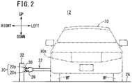
- FIG. 2 shows a schematic overall configuration of the contact type charging system 12 when the electric vehicle 10 is viewed from a front side
- the electric vehicle 10 is a vehicle in which there are mounted an electric motor 14 serving as a drive source, and a driving energy storage device 16 for supplying electrical power to the electric motor 14, and corresponds, for example, to an electric automobile, a hybrid vehicle equipped with an internal combustion engine, and a fuel cell vehicle equipped with a fuel cell.
- the front and rear, left and right, and upper and lower directions will be described in accordance with the directions of the arrows shown in FIGS. 1 and 2 .
- the contact type charging system 12 is constituted at least from power lines 20 made of a conductive material to which electrical power is supplied, and the electric vehicle 10, which is equipped with a charging arm 22 capable of being placed in contact with the power lines 20.
- the charging arm 22 is provided on a side portion 10s on the side of a driver's seat 18 on the right side of the electric vehicle 10, and is disposed between the front wheels WF and the rear wheels WR. In countries in which roads are for right side traveling, the driver's seat 18 generally is located on the left side of the electric vehicle 10, and therefore, the charging arm 22 is disposed on a side portion on the left side of the electric vehicle 10.
- the power lines 20 are arranged along a travel path (road) 24 on which the electric vehicle 10 travels, and are arranged in facing relation to the side portion 10s on the driver's seat 18 side of the electric vehicle 10.
- the power lines 20 are arranged on the side of a central line of the travel path 24.
- the power lines 20 are arranged in the vicinity of the central line and are not disposed respectively in each of the lanes. Further, in the case of a road in which there is a central dividing median, the power lines 20 may be arranged on the median.
- the power lines 20 may be disposed at the length of a specified section.
- the length of the specified section for example, may be set to a length that is capable of charging the electric vehicle 10, so as to be capable of traveling from a position where certain power lines 20 are disposed to the position where next power lines 20 are disposed. While traveling along the power lines 20 on a travel path 24 on which the power lines 20 are arranged, a charging head 26 provided on the distal end of the charging arm 22 of the electric vehicle 10 is extended outwardly in the vehicle transverse direction, and the energy storage device 16 is charged by the charging head 26 coming into contact with the power lines 20.
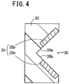
- FIG. 3 is a view showing an installation structure for the power lines 20, and FIG. 4 is a cross-sectional view taken along line IV-IV of FIG. 3 .
- the power lines 20 are retained by a power line retaining unit 30 made of an insulating material, and the power line retaining unit 30 is supported from a rear side thereof by guard posts 32 disposed at predetermined intervals along the travel path 24.
- the guard posts 32 support the power line retaining unit 30 so that the height thereof enables the power lines 20 to come into contact with the distal end of the charging arm 22.
- the power line retaining unit 30 maintains the power lines 20 along the lengthwise direction of the power lines 20.
- a power source 34 supplies electrical power to the power lines 20.
- the power lines 20 include a positive electrode side power line 20p made of a conductive material, and a negative electrode side power line 20n made of a conductive material and arranged below the positive electrode side power line 20p.
- a first voltage which is a high DC voltage
- a second voltage which is a low DC voltage (reference voltage) of a lower direct current than the first voltage, is imposed on the negative electrode side power line 20n from the power source 34.
- a front side of the power line retaining unit 30 is shaped in the form of a V-shaped groove 36 so as to open in the vertical direction.
- the positive electrode side power line 20p is embedded therein so that a front surface thereof is exposed on an upper surface 36a of the V-shaped groove 36
- the negative electrode side power line 20n is embedded therein so that a front surface thereof is exposed on a lower surface 36b of the V-shaped groove 36.
- the voltage imposed on the power lines 20 (20p, 20n) may also be an AC voltage.
- the power lines 20, the power line retaining unit 30, and the power source 34 make up an electrical power supplying device 38 that supplies electrical power to the electric vehicle 10.
- FIG. 5 is a view showing an example of the electrical power supplying device 38 disposed on a travel path 24.
- a one-side three lane travel path 24, or stated otherwise, a six lane road is illustrated, in which a central median 39 serving as a central line is disposed on the road.
- One of the travel paths 24 is a travel path 24a along which the electric vehicle 10 travels, and the other of the travel paths 24 is a travel path 24b along which an oncoming vehicle travels.
- the central median 39 which serves as a central line, serves to partition the travel path 24a and the travel path 24b.
- power line retaining units 30 that retain the power lines 20 are disposed respectively corresponding to the travel paths 24a, 24b.
- the power line retaining unit 30 that is disposed corresponding to the travel path 24a is disposed on the travel path 24b side of the travel path 24a
- the power line retaining unit 30 that is disposed corresponding to the travel path 24b is disposed on the travel path 24a side of the travel path 24b.
- the power source 34 is disposed between the travel path 24a and the travel path 24b. As shown in FIG. 5 , the power source 34 is disposed on the central median 39. Owing thereto, the power source 34 that supplies power to the power lines 20 disposed on the travel paths 24a, 24b can be used in common.
- a single power source 34 supplies electrical power with respect to the power lines 20 of both of the travel paths 24a, 24b. Consequently, complexity of the electrical wiring from the power source 34 to the power lines 20 of the travel paths 24a, 24b can be suppressed.
- the power line retaining units 30 that retain the power lines 20 of the travel paths 24a, 24b may also be disposed on the central median 39.
- the power line retaining unit 30 corresponding to the travel path 24a is disposed on the side of the travel path 24a
- the power line retaining unit 30 corresponding to the travel path 24b is disposed on the side of the travel path 24b.
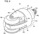
- FIG. 6 is a perspective view of the charging head 26
- FIG. 7 is a side view of the charging head 26
- FIG. 8 is a plan view of the charging head 26.
- the charging head 26 comprises a positive electrode side power receiving element 40p in the form of a roller that contacts the positive electrode side power line 20p of the power lines 20, and a negative electrode side power receiving element 40n in the form of a roller that contacts the negative electrode side power line 20n of the power lines 20.
- the positive electrode side power receiving element 40p and the negative electrode side power receiving element 40n are provided vertically in a pair.
- Power receiving elements 40 (40p, 40n) are disposed on a distal end side of the charging head 26.
- the power receiving elements 40p, 40n are formed from a conductive material. As shown in FIG.
- the power receiving elements 40p, 40n are each of the same structure and shape, and include a first roller member 42a having a substantially frustoconical shape, and a second roller member 42b having a substantially cylindrical shape and disposed on a bottom surface side of the first roller member 42a.
- the first roller member 42a and the second roller member 42b are formed integrally with centers thereof arranged on the same axis (coaxially).
- the cylindrically shaped second roller members 42b have an outer circumferential surface of a first radius r1, and the outer circumferential surface of the first roller members 42a include radii that are larger than the first radius r1. Owing thereto, the first roller members 42a can be placed in contact with respect to the power lines 20, and the circumferential velocity of the outer circumferential surface of the second roller members 42b is smaller in comparison with that of the first roller members 42a. More specifically, the first roller member 42a is substantially in the form of a truncated cone, the bottom surface of which is formed with a circular second radius r2 that is greater than the first radius r1, and the upper surface of which is formed with a circular third radius r3 that is smaller than the second radius r2. Stated otherwise, the outer circumferential surface of the first roller member 42a is formed by the second radius r2 and the third radius r3. The third radius r3 may be either smaller or larger than the first radius r1.
- the power receiving elements 40p, 40n are mounted on the charging head 26 by being separated in a vertically symmetrical manner, such that the second roller members 42b face toward one another mutually. It is possible for the positive electrode side power line 20p and the negative electrode side power line 20n provided in the V-shaped groove 36 to be contacted by the first roller members 42a of the positive electrode side power receiving element 40p and the negative electrode side power receiving element 40n.
- the first roller members 42a may also be formed in a cylindrical columnar shape of the second radius r2. In this case, there is no need for the V-shaped groove 36 to be provided in the power line retaining unit 30.
- the power receiving elements 40p, 40n are axially supported rotatably by a rotary support member 46 that is mounted on a main body portion 44 of the charging head 26.
- the rotary support member 46 includes a first support member 46a that rotatably supports the power receiving element 40p, and a second support member 46b that rotatably supports the power receiving element 40n.
- the first support member 46a includes a support shaft (central shaft) 48a that extends in a vertical direction supporting the power receiving element 40p, and the power receiving element 40p is attached rotatably to the support shaft 48a through a bearing 50a.
- the second support member 46b includes a support shaft (central shaft) 48b that extends in a vertical direction supporting the power receiving element 40n, and the power receiving element 40n is attached rotatably to the support shaft 48b through a bearing 50b.
- the first support member 46a and the second support member 46b have the same shape, and are attached in a vertically symmetrical manner to the main body portion 44.
- the main body portion 44 includes a base section 52 having a disk-shaped flange 52a, and a partition plate 54 disposed contiguously toward the distal end side of the charging head 26 from a side surface of the flange 52a, and which vertically partitions the power receiving element 40p and the power receiving element 40n.
- the first support member 46a is attached upwardly of the partition plate 54, and the second support member 46b is attached downwardly of the partition plate 54.
- Distal end parts of the power receiving elements 40p, 40n (distal ends of the first roller members 42a) project out more toward the distal end side than the partition plate 54. Consequently, the distal end parts of the power receiving elements 40p, 40n can be placed in contact with the power lines 20. Further, as shown in FIG. 6 , the rearward side of the main body portion 44 and the power receiving elements 40p, 40n are covered by a cover 56.
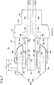
- a conductive brush (contact conductor) 58a that contacts the second roller member 42b of the power receiving element 40p is disposed slidably along a longitudinal direction of the charging head 26 (the directions of the arrow x in FIGS. 7 and 8 ) in the interior of the first support member 46a.
- a contact surface of the brush 58a in contact with the second roller member 42b includes an arcuate shape in accordance with the shape of the second roller member 42b.
- two conductive bus bars 60a, 60a extend through a through hole 62a formed in the interior of the base section 52 and a through hole 64a formed in the interior of the first support member 46a, and are connected electrically to the brush 58a.
- the two bus bars 60a, 60a are connected to the brush 58a over a predetermined interval in the horizontal direction. Other ends of the bus bars 60a, 60a are fixed in a non-movable state, and are connected electrically to the energy storage device 16 of the electric vehicle 10 through electrical cables 86a disposed in the interior of an arm portion 86 (see FIG. 10 ) of the charging arm 22.
- the through hole 62a communicates with the through hole 64a by being branched into two in a horizontal direction in the interior of the flange 52a of the base section 52.
- An opening 66a of the through hole 64a has a size that covers two openings 68a, 68a of the through hole 62a that is formed in the flange 52a.
- a conductive brush (contact conductor) 58b that contacts the second roller member 42b of the power receiving element 40n is disposed slidably along a longitudinal direction of the charging head 26 in the interior of the second support member 46b.
- a contact surface of the brush 58b in contact with the second roller member 42b includes an arcuate shape in accordance with the shape of the second roller member 42b.
- two conductive bus bars 60b, 60b extend through a through hole 62b formed in the interior of the base section 52 and a through hole 64b formed in the interior of the second support member 46b, and are connected to the brush 58b. The two bus bars 60b, 60b are connected to the brush 58b over a predetermined interval in the horizontal direction.
- bus bars 60b, 60b are fixed in a non-movable state, and are connected electrically to the energy storage device 16 of the electric vehicle 10 through electrical cables 86b disposed in the interior of the arm portion 86 (see FIG. 10 ) of the charging arm 22.
- the through hole 62b communicates with the through hole 64b by being branched into two in a horizontal direction in the interior of the flange 52a of the base section 52.
- An opening 66b of the through hole 64b has a size that covers two openings 68b, 68b of the through hole 62b that is formed in the flange 52a.
- the brushes 58a, 58b are biased (pressed) in the direction of the arrow x toward the sides of the second roller members 42b (toward the distal end side of the charging head 26). Owing thereto, even if the power receiving elements 40p, 40n and/or the brushes 58a, 58b become abraded, due to the spring members 70a, 70b, the brushes 58a, 58b can be pressed against the second roller members 42b of the power receiving elements 40p, 40n by sliding (or being moved) toward the distal end side.
- the first voltage can be transmitted reliably to the bus bars 60a, 60a from the positive electrode side power line 20p through the positive electrode side power receiving element 40p
- the second voltage can be transmitted reliably to the bus bars 60b, 60b from the negative electrode side power line 20n through the negative electrode side power receiving element 40n.
- the bus bars 60a, 60a at the interior of the through holes 62a, 64a, and the bus bars 60b, 60b at the interior of the through holes 62b, 64b are retained to a certain degree in a slackened state. Stated otherwise, in comparison with a length of a shortest distance of the bus bars 60a, 60b that interconnects the distal end sides of the electrical cables 86a, 86b and the brushes 58a, 58b, a length of the bus bars 60a, 60b is set to possess a further surplus length, and the surplus length thereof is subjected to slackening in the interior of the through holes 62a, 64a and the through holes 62b, 64b. Owing thereto, the bus bars 60a, 60b can be allowed to follow along with the movement of the brushes 58a, 58b, and thus, the brushes 58a, 58b can be moved toward the side of the power receiving elements 40p, 40n.
- One end of the spring member 70a is mounted on the brush 58a between the two bus bars 60a, 60a, and the other end of the spring member 70a is mounted on the flange 52a between the openings 68a, 68a.
- one end of the spring member 70b is mounted on the brush 58b between the two bus bars 60b, 60b, and the other end of the spring member 70b is mounted on the flange 52a between the openings 68b, 68b.
- wear debris generated by rotation of the power receiving element 40p may fall downwardly and impart an adverse influence on the power receiving element 40n.
- an influence will be effected on the contact state between the power lines 20 and the power receiving element 40n, or that the power receiving element 40p cannot be rotated smoothly, or that an arc may be generated.
- a recessed part 54a is provided, which is recessed a predetermined depth in an upper surface of the partition plate (accommodating section) 54 that is disposed between the power receiving elements 40p, 40n.
- the recessed part 54a is formed around an outer periphery of the partition plate 54. Since wear debris, which is generated by contact friction between the first roller member 42a of the power receiving element 40p and the positive electrode side power line 20p, is accommodated in the recessed part 54a, scattering about of the wear debris that is generated by contact friction between the first roller member 42a of the power receiving element 40p and the positive electrode side power line 20p can be prevented. Accordingly, the occurrence of adverse effects such as insulation defects or the like in peripheral components can be suppressed.
- the recessed part 54a is formed in the partition plate 54 so as to surround the contact position between the power receiving element 40p and the brush 58a. Consequently, since wear debris, which is generated by contact friction between the second roller member 42b of the power receiving element 40p and the brush 58a, is accommodated in the recessed part 54a, scattering about of the wear debris that is generated by contact friction between the second roller member 42b of the power receiving element 40p and the brush 58a can be prevented. Accordingly, the occurrence of adverse effects such as insulation defects or the like in peripheral components can be suppressed.
- the charging arm 22 includes, apart from the charging head 26, a bracket 80 to which the charging head 26 is attached, and a slider crank mechanism 82 by which the charging head 26 is moved (rotated) through the bracket 80 in the directions of the arrow q (q1, q2).
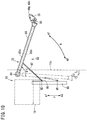
- the slider crank mechanism 82 includes the arm portion 86, which is deployed horizontally in a vehicle transverse and outward direction by rotating about a rotary shaft 84 provided on the electric vehicle 10, a slide rail 88, which is mounted along the longitudinal direction of the vehicle body more on an inner side of the vehicle body of the electric vehicle 10 than the arm portion 86, an actuator 90 that slides on the slide rail 88 in the directions of the arrow p (p1, p2), and a spring damper 92, one end of which is attached rotatably to the arm portion 86, and another end of which is attached rotatably to the actuator 90.
- the charging head 26 is attached to the distal end side (a side opposite to the rotary shaft 84) of the arm portion 86 through the bracket 80.
- the spring damper 92 biases the arm portion 86 in a direction to deploy the arm portion 86 outwardly in the vehicle transverse direction.
- the arm portion 86 When the actuator 90 moves on the slide rail 88 in the direction of the arrow p1, the arm portion 86 is rotated about the rotary shaft 84 in the direction of the arrow q1, and the charging head 26 is also moved together therewith in the direction of the arrow q1. As a result, the arm portion 86 opens horizontally about the rotary shaft 84 from a lateral side of the vehicle body of the electric vehicle 10, and the charging head 26 moves to the side of the power lines 20.
- the position of the actuator 90 when the charging head 26 is accommodated (the state shown by the two-dot-dashed lines of FIG. 10 ) is regarded as an initial position d1, and in the case that charging is to be carried out, the actuator 90 is moved from the initial position d1 to a predetermined position d2 along the direction of the arrow p1. Consequently, the arm portion 86 is deployed up to a first angle of rotation ⁇ 1, and the charging head 26 projects (outwardly of the electric vehicle 10) toward the side of the power lines 20 (the state shown by the solid lines of FIG. 10 ).
- the angle of rotation refers to an angle from the state in which the arm portion 86 is accommodated.
- the charging head 26 when the arm portion 86 is deployed up to the first angle of rotation ⁇ 1, the charging head 26 can be placed in contact with the power lines 20, which are separated a first predetermined distance z1 from the side portion 10s on the side of the driver's seat 18 of the electric vehicle 10. Additionally, when the distance to the power lines 20 from the side portion 10s on the side of the driver's seat 18 of the electric vehicle 10 becomes shorter than the first predetermined distance z1, the charging head 26 is pressed by the power lines 20, whereupon the arm portion 86 undergoes rotation in the direction (closing direction) of the arrow q2 in opposition to the biasing force of the spring damper 92. Along therewith, the charging head 26 also is moved in the direction of the arrow q2 (toward the side of the vehicle body).
- the range within which the charging head 26 can be moved in the direction of the arrow q2 is limited.
- the angle of rotation of the arm portion 86 at the time that the spring damper 92 is contracted maximally will be referred to as a second angle of rotation ⁇ 2.
- the arm portion 86 can be rotated within the range of the second angle of rotation ⁇ 2 from the first angle of rotation ⁇ 1.
- the distance between the power lines 20, which are contacted by the power receiving elements 40p, 40n of the charging head 26 when the arm portion 86 is at the second angle of rotation ⁇ 2, and the side portion 10s on the side of the driver's seat 18 of the electric vehicle 10 becomes a second predetermined distance z2 that is shorter than the first predetermined distance z1.
- the angle of rotation of the arm portion 86 does not become smaller than the second angle of rotation ⁇ 2, and therefore, the distance between the power lines 20 and the side portion 10s on the side of the driver's seat 18 of the electric vehicle 10 (also referred to as a "distance between the electric vehicle 10 and the power lines 20) does not become less than the second predetermined distance z2.
- the angle of rotation can be controlled by controlling or interlocking the retraction of the spring damper 92 and movement of the actuator 90.
- the contact pressure between the power lines 20 and the power receiving elements 40p, 40n due to the spring damper 92 can be controlled more finely.
- the rotational range of the arm portion 86 is limited to within a predetermined angular range.
- the contact pressure between the power lines 20 and the power receiving elements 40p, 40n of the charging head 26 can be maintained by the spring damper 92, and thus they can be allowed to contact one another in a stable manner.
- a guideline 100 for guiding the distance between the electric vehicle 10 and the power lines 20 may be disposed on the travel path 24.
- the guideline 100 also constitutes part of the contact type charging system 12.
- the charging head 26 When the rotational angle of the arm portion 86 is at the third angle of rotation ⁇ 3, the charging head 26 is attached to the arm portion 86 through the bracket 80, such that the longitudinal direction of the charging head 26 faces toward the power lines 20 at a direction perpendicular with respect to the power lines 20. Stated otherwise, the charging head 26 is attached to the distal end of the arm portion 86 through the bracket 80, in such a manner that the longitudinal direction of the charging head 26 with respect to the longitudinal direction of the arm portion 86 (direction of extension) is bent toward the side of the opening direction of the arm portion 86.
- the longitudinal direction of the charging head 26 and the longitudinal direction of the arm portion 86 define a predetermined angle.
- the charging head 26 is disposed so that the longitudinal direction of the charging head 26 is perpendicular with respect to the power lines 20 when the rotational angle of the arm portion 86 is at the first angle of rotation ⁇ 1, and the distance between the electric vehicle 10 and the power lines 20 has become the second predetermined distance z2, then the angle ⁇ of the charging head 26 with respect to the power lines 20 becomes excessively small compared to the angles ⁇ 1, ⁇ 2.
- the charging head 26 is disposed so that the longitudinal direction of the charging head 26 is perpendicular with respect to the power lines 20 when the rotational angle of the arm portion 86 is at the second angle of rotation ⁇ 2, and the distance between the electric vehicle 10 and the power lines 20 has become the first predetermined distance z1, then the angle ⁇ of the charging head 26 with respect to the power lines 20 becomes excessively small compared to the angles ⁇ 1, ⁇ 2.
- the charging head 26 by disposing the charging head 26 so that the longitudinal direction of the charging head 26 faces toward the power lines 20 (i.e., so that the charging head 26 and the power lines 20 are disposed face to face) when the rotational angle of the arm portion 86 is at the third angle of rotation ⁇ 3, even if the distance between the electric vehicle 10 and the power lines 20 varies within a range from the first predetermined distance z1 to the second predetermined distance z2, the power receiving elements 40p, 40n of the charging head 26 can stably be placed in contact with the power lines 20.
- the charging head 26 when the arm portion 86 is deployed so as to be placed at the third angle of rotation ⁇ 3, the charging head 26 is set so that the longitudinal direction thereof faces toward the power lines 20 perpendicularly with respect to the power lines 20 (i.e., so that the charging head 26 and the power lines 20 are disposed face to face), and the arm portion 86 is deployed up to the first angle of rotation ⁇ 1 which is greater than the third angle of rotation ⁇ 3. Consequently, it is possible for the power receiving elements 40p, 40n and the power lines 20 to stably be placed in contact with each other, even if the angle ⁇ formed by the charging head 26 and the power lines 20 varies due to the variation of the distance between the electric vehicle 10 and the power lines 20.
- the charging arm 22 includes the actuator 90 that slides along the slide rail 88, and the spring damper 92, one end of which is attached rotatably to the arm portion 86, and another end of which is attached rotatably to the actuator 90, and the spring damper 92 biases the arm portion 86 in a direction to deploy the arm portion 86 outwardly in the vehicle transverse direction. Accordingly, when the power receiving elements 40p, 40n contact the power lines 20 and the arm portion 86 is returned to the side of the electric vehicle 10, the power receiving elements 40p, 40n are pressed against the power lines 20 by the biasing force of the spring damper 92. Consequently, the contact pressure between the power receiving elements 40p, 40n and the power lines 20 can be maintained, and electrical power from the power lines 20 can be supplied in a stable manner to the energy storage device 16.
- the charging head 26 is attached to the distal end of the arm portion 86 through a bracket 80, in such a manner that the longitudinal direction of the charging head 26 and a direction in which the arm portion 86 extends define a predetermined angle. Accordingly, when the arm portion 86 is deployed to the third angle of rotation ⁇ 3, the charging head 26 can easily be attached to the distal end of the arm portion 86, so that the longitudinal direction of the charging head 26 faces toward the power lines 20 at a direction perpendicular with respect to the power lines 20.
- the power lines 20 come into contact with the first roller members 42a of the power receiving elements 40p, 40n, and the brushes 58a, 58b are placed in contact with the second roller members 42b of the power receiving elements 40p, 40n. More specifically, the positions at which the power receiving elements 40p, 40n contact the power lines 20 are shifted in the axial direction of the support shafts 48a, 48b from the positions at which the power receiving elements 40p, 40n contact the brushes 58a, 58b. Owing thereto, abrasion of the power receiving elements 40p, 40n at the contact position between the power receiving elements 40p, 40n and the power lines 20 can be suppressed. Consequently, the power receiving elements 40p, 40n and the power lines 20 can stably be kept in contact, and electrical power from the power lines 20 can be supplied in a stable manner to the energy storage device 16.
- the charging head 26 is equipped with the spring members 70a, 70b that press the brushes 58a, 58b toward the side of the power receiving elements 40p, 40n. Owing to this feature, even in the case that the power receiving elements 40p, 40n or the brushes 58a, 58b are abraded and subjected to wear due to contact between the power receiving elements 40p, 40n and the brushes 58a, 58b, the contact state between the power receiving elements 40p, 40n and the brushes 58a, 58b can be maintained by the spring members 70a, 70b.
- the bus bars 60a, 60b that connect the brushes 58a, 58b and the electrical cables 86a, 86b are retained in a slackened state. Owing thereto, the bus bars 60a, 60b can be allowed to follow along with the movement of the brushes 58a, 58b, and thus, the brushes 58a, 58b can be moved toward the side of the power receiving elements 40p, 40n. Consequently, the contact state between the brushes 58a, 58b and the power receiving elements 40p, 40n can be maintained.
- the power receiving elements 40p, 40n are equipped with the first roller members 42a that contact the power lines 20, and the second roller members 42b having the outer circumferential surface of a first radius r1 and which contact the brushes 58a, 58b, and further, the outer circumferential surface of the first roller members 42a include radii that are larger than the first radius r1. Owing thereto, the first roller members 42a can be placed in contact with respect to the power lines 20. Further, the circumferential velocity of the outer circumferential surface of the second roller members 42b is smaller in comparison with that of the first roller members 42a, whereby frictional wear and abrasion between the second roller members 42b and the brushes 58a, 58b can be suppressed.
- the charging arm 22 extends outwardly in the vehicle transverse direction from the side portion 10s on the driver's seat 18 side of the electric vehicle 10, the driver can easily grasp and comprehend the distance between the electric vehicle 10 and the power lines 20, and by steering a non-illustrated steering handle, the contact state between the power lines 20 and the power receiving elements 40p, 40n of the charging arm 22 can suitably be maintained.
- the distance between the electric vehicle 10 and the power lines 20 can be maintained at an appropriate distance. Consequently, the contact state between the power lines 20 and the power receiving elements 40p, 40n of the charging arm 22 can suitably be maintained.
- the power source 34 that supplies electrical power to the power lines 20 is disposed between the travel path 24a on which the electric vehicle 10 travels and the travel path 24b on which oncoming vehicles travel, the power source 34 can be used in common with the travel path 24a and the travel path 24b. Consequently, complexity of the electrical wiring from the power source 34 to the power lines 20 of the travel paths 24a, 24b can be suppressed.
- the recessed part 54a which is recessed at a predetermined depth, is formed on the upper surface of the partition plate 54 of the charging head 26, even in the case that the power receiving element 40p or the power line 20p is subjected to frictional wear due to contact between the power receiving element 40p and the power line 20p, wear debris therefrom can be accommodated in the recessed part 54a. As a result, the occurrence of adverse effects such as insulation defects or the like in peripheral components by scattering about of such wear debris from the power receiving element 40p or the power line 20p can be suppressed.
- the recessed part 54a is formed in the partition plate 54 so as to surround the contact position between the power receiving element 40p and the brush 58a. Owing thereto, even if wear debris is generated by frictional wearing between the power receiving element 40p and the brush 58a, the wear debris can be accommodated in the partition plate 54. As a result, generation of adverse effects such as insulation defects or the like in peripheral components by wear debris due to contact between the power receiving element 40p and the brush 58a can be suppressed.
- the charging head 26 is equipped with the two positive electrode and negative electrode power receiving elements 40p, 40n in a pair, which are separated mutually in the vertical direction, and the partition plate 54 is arranged between the pair of power receiving elements 40p, 40n in the vertical direction. Owing thereto, for example, falling down of wear debris, which is generated by the power receiving element 40p that is arranged on the upper side, to the side of the power receiving element 40n on the lower side, and imparting of an adverse effect on the contact state between the power receiving element 40n and the power line 20n can be suppressed. Consequently, electrical power from the power lines 20 can be supplied in a stable manner to the energy storage device 16 through the pair of power receiving elements 40p, 40n.
- FIG. 12 is a view showing a charging head 26A according to the present modification
- FIG. 13 is a view showing a main body portion 44A illustrated in FIG. 12 .
- the capital letter A is appended to the reference numerals concerning constituent elements having the same functions as those of FIG. 1 , and only necessary locations thereof will be described.
- a through hole 62aA provided in a base section 52A of the main body portion 44A branches into two in the interior of a flange 52aA, and communicates with two openings 68aA, 68aA that are formed in the flange 52aA.
- the through holes 62aA are formed horizontally in the interior of the base section 52A, and the cross-sectional areas thereof are of the same size.
- the recessed part 110 is formed in an upper surface of a partition plate 54A on the side of the openings 68aA, 68aA.
- the recessed part 110 is formed so that two bus bars 60aA, 60aA, which extend from the two openings 68aA, 68aA horizontally through the through holes 62aA, will not interfere with the partition plate 54A.
- the two bus bars 60aA, 60aA extend from the openings 68aA, 68aA in an upwardly bending manner, and are connected to a brush 58aA through the inside of a first support member 46aA (not shown).
- the two bus bars 60aA, 60aA are retained in a slackened state in the interior of a through hole 64aA of the first support member 46aA (not shown).
- Another recessed part 54aA which is recessed at a predetermined depth around an outer periphery thereof, is formed on the upper surface of the partition plate (accommodating section) 54A.
- Wear debris which is generated by contact friction between a positive electrode side power line 20pA and a power receiving element 40pA, and wear debris, which is generated by contact friction between the power receiving element 40pA and the brush 58aA is accommodated by the recessed part 54aA.
- the communicating state of non-illustrated bus bars 60bA, 60bA is the same as that of the bus bars 60aA, 60aA. More specifically, differently from the above-described embodiment, through holes 62bA are formed horizontally in the interior of the base section 52A, and the cross-sectional areas thereof are of the same size. In addition, a recessed part 110 is formed in a lower surface of the partition plate 54A on the side of openings 68bA, 68bA. The recessed part 110 is formed so that the two bus bars 60bA, 60bA, which extend from the two openings 68bA, 68bA horizontally through the through holes 62bA, will not interfere with the partition plate 54A.
- the two bus bars 60bA, 60bA extend from the openings 68bA, 68bA in an downwardly bending manner, and are connected to a brush 58bA through the inside of a second support member 46bA (not shown). According to the present modification, the two bus bars 60bA, 60bA are retained in a slackened state in the interior of a through hole 64bA of the second support member 46bA (not shown).
- a recess 112 formed in the upper surface of the partition plate 54A is formed for the purpose of receiving a support shaft 48aA therein, and similarly, in the lower surface of the partition plate 54A, a recess (not shown) is formed for the purpose of receiving a support shaft 48bA therein.
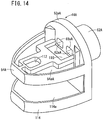
- an accommodating section 114 in which a recessed part 114a is formed on a lower portion of the charging head 26A (main body portion 44A) may be provided for accommodating wear debris, which is generated by contact friction between a negative electrode side power line 20nA and a power receiving element 40nA, and wear debris, which is generated by contact friction between the power receiving element 40nA and the brush 58bA.
- the recessed part 114a is formed on the upper surface of the accommodating section 114.
Description
- The present invention relates to an electric vehicle that charges an energy storage device of the electric vehicle by bringing a charging head into contact with power lines through which electrical power is supplied during traveling.
- In Japanese Laid-Open Patent Publication No.
2013-233037 claim 1, charging of an energy storage device of an electric vehicle is disclosed in which, during traveling of the electric vehicle, power receiving elements (rollers) of a charging head disposed on a distal end of an arm portion of the electric vehicle are brought into contact while undergoing rotation with power lines to which electric power is supplied. The charging arm compensates for small distance variations in the vertical direction when the vehicle swings. - Besides, Japanese Laid-Open Patent Publication No.
H02-273004 - Provisionally, in the case of a configuration in which a longitudinal direction of the charging head is arranged perpendicularly to the power lines when the arm portion is open, if the distance between the electric vehicle and the power lines becomes shorter, the arm portion is returned toward the side of the electric vehicle in a state in which the charging head is in contact with the power lines. For this reason, as the distance between the electric vehicle and the power lines becomes shorter, the angle defined by the longitudinal direction of the charging head and the power lines gradually becomes smaller. Consequently portions apart from the power receiving elements of the charging head interfere with the power lines, and it becomes impossible for the charging member to remain in contact with the power lines.
- The present invention has the object of providing an electric vehicle that enables power receiving elements and power lines to stably remain in contact with each other, even in the case that the angle formed by a charging head and the power lines vary due to a variation in the distance between the electric vehicle and the power lines.
- The present invention is characterized by an electric vehicle that charges an energy storage device configured to drive the electric vehicle, by bringing power receiving elements of a charging arm into contact with power lines, which are disposed along a travel path of the electric vehicle together with facing toward a side portion of the electric vehicle, and to which electrical power is supplied, wherein the charging arm comprises an arm portion configured to be deployed, during charging, from the side portion of the electric vehicle toward an outer side in a vehicle transverse direction by rotating the charging arm about a rotary shaft, the power receiving elements are disposed in a charging head configured to be positioned on a distal end of the arm portion, the charging head is set so as to face toward the power lines at an orientation in which a longitudinal direction of the charging head is perpendicular to the power lines in a case where the arm portion is deployed at a predetermined angle of rotation about the rotary shaft as from the state in which the arm portion is accommodated, and the arm portion is deployed up to a first angle of rotation about the rotary shaft as from the state in which the arm portion is accommodated, the first angle of rotation being greater than the predetermined angle of rotation.
- According to the present invention, in the electric vehicle, the charging arm includes an actuator configured to slide along a slide rail, and a spring damper comprising one end attached rotatably to the arm portion, and another end attached rotatably to the actuator, and the spring damper biases the arm portion in a direction to deploy the arm portion outwardly in the vehicle transverse direction.
- According to the present invention, in the electric vehicle, the actuator is configured to slide along the slide rail when the slide rail is disposed in a longitudinal direction of the electric vehicle.
- According to the present invention, in the electric vehicle, the charging head is attached to a distal end of the arm portion through a bracket, to define a predetermined angle between the longitudinal direction of the charging head and a direction in which the arm portion extends.
- According to the present invention, since the arm portion is deployed to the first angle of rotation that is greater than the predetermined angle of rotation, even in the case that the distance between the electric vehicle and the power lines is varied by the power receiving elements contacting the power lines and the arm portion being returned to the side of the electric vehicle, the power receiving elements and the power lines can stably be kept in contact with each other.
- According to the present invention, since the spring damper biases the arm portion in a direction to deploy the arm portion outwardly in the vehicle transverse direction, when the arm portion is brought into contact with the power lines and returned to the side of the electric vehicle, the power receiving elements are pressed against the power lines by the biasing force of the spring damper. Consequently, the contact pressure between the power receiving elements and the power lines can be maintained, and electrical power from the power lines can be supplied in a stable manner to the energy storage device.
- According to the present invention, since the charging head is attached to the distal end of the arm portion through a bracket, in such a manner that the longitudinal direction of the charging head and a direction in which the arm portion extends define a predetermined angle, at a time that the arm portion is deployed to the predetermined angle, the charging head can simply be attached to the distal end of the arm portion so that the longitudinal direction thereof faces toward the power lines at a direction perpendicular with respect to the power lines.
-
-
FIG. 1 is a view showing a schematic overall configuration of a contact type charging system when an electric vehicle according to an embodiment of the invention is viewed from an upper side; -
FIG. 2 is a view showing a schematic overall configuration of the contact type charging system when an electric vehicle according to an embodiment of the invention is viewed from a front side; -
FIG. 3 is a view showing an installation structure for the power lines shown inFIG. 1 ; -
FIG. 4 is a cross-sectional view taken along line IV-IV ofFIG. 3 ; -
FIG. 5 is a view showing an example of an electrical power supplying device provided on a travel path; -
FIG. 6 is a perspective view of a charging head shown inFIG. 1 ; -
FIG. 7 is a side view of the charging head shown inFIG. 1 ; -
FIG. 8 is a plan view of the charging head shown inFIG. 1 ; -
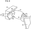
FIG. 9 is a view showing a state of contact between the charging head and the power lines; -
FIG. 10 is a schematic view of a charging arm shown inFIG. 1 ; -
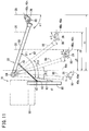
FIG. 11 is a view showing a relationship between an angle of rotation of the charging arm, and a distance to the power lines from a side portion on a driver's seat side of the electric vehicle; -
FIG. 12 is a view showing a charging head according to a modification; -
FIG. 13 is a view showing a main body portion illustrated inFIG. 12 ; and -
FIG. 14 is a view showing an example in which an accommodating section is disposed on a lower part of the main body portion according to a modification. - A preferred embodiment of an electric vehicle according to the present embodiment will be described in detail below with reference to the accompanying drawings.
-
FIG. 1 shows a schematic overall configuration of a contacttype charging system 12 when anelectric vehicle 10 is viewed from an upper side, andFIG. 2 shows a schematic overall configuration of the contacttype charging system 12 when theelectric vehicle 10 is viewed from a front side. Theelectric vehicle 10 is a vehicle in which there are mounted anelectric motor 14 serving as a drive source, and a drivingenergy storage device 16 for supplying electrical power to theelectric motor 14, and corresponds, for example, to an electric automobile, a hybrid vehicle equipped with an internal combustion engine, and a fuel cell vehicle equipped with a fuel cell. The front and rear, left and right, and upper and lower directions will be described in accordance with the directions of the arrows shown inFIGS. 1 and2 . - The contact
type charging system 12 is constituted at least frompower lines 20 made of a conductive material to which electrical power is supplied, and theelectric vehicle 10, which is equipped with acharging arm 22 capable of being placed in contact with thepower lines 20. Thecharging arm 22 is provided on aside portion 10s on the side of a driver'sseat 18 on the right side of theelectric vehicle 10, and is disposed between the front wheels WF and the rear wheels WR. In countries in which roads are for right side traveling, the driver'sseat 18 generally is located on the left side of theelectric vehicle 10, and therefore, thecharging arm 22 is disposed on a side portion on the left side of theelectric vehicle 10. - The
power lines 20 are arranged along a travel path (road) 24 on which theelectric vehicle 10 travels, and are arranged in facing relation to theside portion 10s on the driver'sseat 18 side of theelectric vehicle 10. Thepower lines 20 are arranged on the side of a central line of thetravel path 24. In the case of roads on which there are plural lanes on one side (for example, in the case of roads on which there are two lanes or three lanes on one side), thepower lines 20 are arranged in the vicinity of the central line and are not disposed respectively in each of the lanes. Further, in the case of a road in which there is a central dividing median, thepower lines 20 may be arranged on the median. - The
power lines 20 may be disposed at the length of a specified section. The length of the specified section, for example, may be set to a length that is capable of charging theelectric vehicle 10, so as to be capable of traveling from a position wherecertain power lines 20 are disposed to the position wherenext power lines 20 are disposed. While traveling along thepower lines 20 on atravel path 24 on which thepower lines 20 are arranged, a charginghead 26 provided on the distal end of thecharging arm 22 of theelectric vehicle 10 is extended outwardly in the vehicle transverse direction, and theenergy storage device 16 is charged by the charginghead 26 coming into contact with thepower lines 20. -
FIG. 3 is a view showing an installation structure for thepower lines 20, andFIG. 4 is a cross-sectional view taken along line IV-IV ofFIG. 3 . Thepower lines 20 are retained by a powerline retaining unit 30 made of an insulating material, and the powerline retaining unit 30 is supported from a rear side thereof byguard posts 32 disposed at predetermined intervals along thetravel path 24. Theguard posts 32 support the powerline retaining unit 30 so that the height thereof enables thepower lines 20 to come into contact with the distal end of thecharging arm 22. The powerline retaining unit 30 maintains thepower lines 20 along the lengthwise direction of thepower lines 20. - A
power source 34 supplies electrical power to thepower lines 20. Thepower lines 20 include a positive electrodeside power line 20p made of a conductive material, and a negative electrodeside power line 20n made of a conductive material and arranged below the positive electrodeside power line 20p. A first voltage, which is a high DC voltage, is imposed on the positive electrodeside power line 20p from thepower source 34, and a second voltage, which is a low DC voltage (reference voltage) of a lower direct current than the first voltage, is imposed on the negative electrodeside power line 20n from thepower source 34. A front side of the powerline retaining unit 30 is shaped in the form of a V-shaped groove 36 so as to open in the vertical direction. The positive electrodeside power line 20p is embedded therein so that a front surface thereof is exposed on anupper surface 36a of the V-shaped groove 36, and the negative electrodeside power line 20n is embedded therein so that a front surface thereof is exposed on alower surface 36b of the V-shaped groove 36. The voltage imposed on the power lines 20 (20p, 20n) may also be an AC voltage. Thepower lines 20, the powerline retaining unit 30, and thepower source 34 make up an electricalpower supplying device 38 that supplies electrical power to theelectric vehicle 10. -
FIG. 5 is a view showing an example of the electricalpower supplying device 38 disposed on atravel path 24. InFIG. 5 , a one-side threelane travel path 24, or stated otherwise, a six lane road is illustrated, in which a central median 39 serving as a central line is disposed on the road. One of thetravel paths 24 is atravel path 24a along which theelectric vehicle 10 travels, and the other of thetravel paths 24 is atravel path 24b along which an oncoming vehicle travels. Thecentral median 39, which serves as a central line, serves to partition thetravel path 24a and thetravel path 24b. - As shown in
FIG. 5 , powerline retaining units 30 that retain thepower lines 20 are disposed respectively corresponding to thetravel paths line retaining unit 30 that is disposed corresponding to thetravel path 24a is disposed on thetravel path 24b side of thetravel path 24a, whereas the powerline retaining unit 30 that is disposed corresponding to thetravel path 24b is disposed on thetravel path 24a side of thetravel path 24b. Further, thepower source 34 is disposed between thetravel path 24a and thetravel path 24b. As shown inFIG. 5 , thepower source 34 is disposed on thecentral median 39. Owing thereto, thepower source 34 that supplies power to thepower lines 20 disposed on thetravel paths single power source 34 supplies electrical power with respect to thepower lines 20 of both of thetravel paths power source 34 to thepower lines 20 of thetravel paths - The power
line retaining units 30 that retain thepower lines 20 of thetravel paths central median 39. In this case, the powerline retaining unit 30 corresponding to thetravel path 24a is disposed on the side of thetravel path 24a, whereas the powerline retaining unit 30 corresponding to thetravel path 24b is disposed on the side of thetravel path 24b. -
FIG. 6 is a perspective view of the charginghead 26,FIG. 7 is a side view of the charginghead 26, andFIG. 8 is a plan view of the charginghead 26. The charginghead 26 comprises a positive electrode sidepower receiving element 40p in the form of a roller that contacts the positive electrodeside power line 20p of thepower lines 20, and a negative electrode sidepower receiving element 40n in the form of a roller that contacts the negative electrodeside power line 20n of thepower lines 20. The positive electrode sidepower receiving element 40p and the negative electrode sidepower receiving element 40n are provided vertically in a pair. Power receiving elements 40 (40p, 40n) are disposed on a distal end side of the charginghead 26. Thepower receiving elements FIG. 7 , thepower receiving elements first roller member 42a having a substantially frustoconical shape, and asecond roller member 42b having a substantially cylindrical shape and disposed on a bottom surface side of thefirst roller member 42a. Thefirst roller member 42a and thesecond roller member 42b are formed integrally with centers thereof arranged on the same axis (coaxially). - The cylindrically shaped
second roller members 42b have an outer circumferential surface of a first radius r1, and the outer circumferential surface of thefirst roller members 42a include radii that are larger than the first radius r1. Owing thereto, thefirst roller members 42a can be placed in contact with respect to thepower lines 20, and the circumferential velocity of the outer circumferential surface of thesecond roller members 42b is smaller in comparison with that of thefirst roller members 42a. More specifically, thefirst roller member 42a is substantially in the form of a truncated cone, the bottom surface of which is formed with a circular second radius r2 that is greater than the first radius r1, and the upper surface of which is formed with a circular third radius r3 that is smaller than the second radius r2. Stated otherwise, the outer circumferential surface of thefirst roller member 42a is formed by the second radius r2 and the third radius r3. The third radius r3 may be either smaller or larger than the first radius r1. - The
power receiving elements head 26 by being separated in a vertically symmetrical manner, such that thesecond roller members 42b face toward one another mutually. It is possible for the positive electrodeside power line 20p and the negative electrodeside power line 20n provided in the V-shapedgroove 36 to be contacted by thefirst roller members 42a of the positive electrode sidepower receiving element 40p and the negative electrode sidepower receiving element 40n. Thefirst roller members 42a may also be formed in a cylindrical columnar shape of the second radius r2. In this case, there is no need for the V-shapedgroove 36 to be provided in the powerline retaining unit 30. - The
power receiving elements rotary support member 46 that is mounted on amain body portion 44 of the charginghead 26. Therotary support member 46 includes afirst support member 46a that rotatably supports thepower receiving element 40p, and asecond support member 46b that rotatably supports thepower receiving element 40n. More specifically, thefirst support member 46a includes a support shaft (central shaft) 48a that extends in a vertical direction supporting thepower receiving element 40p, and thepower receiving element 40p is attached rotatably to thesupport shaft 48a through abearing 50a. Similarly, thesecond support member 46b includes a support shaft (central shaft) 48b that extends in a vertical direction supporting thepower receiving element 40n, and thepower receiving element 40n is attached rotatably to thesupport shaft 48b through abearing 50b. Thefirst support member 46a and thesecond support member 46b have the same shape, and are attached in a vertically symmetrical manner to themain body portion 44. - The
main body portion 44 includes abase section 52 having a disk-shapedflange 52a, and apartition plate 54 disposed contiguously toward the distal end side of the charginghead 26 from a side surface of theflange 52a, and which vertically partitions thepower receiving element 40p and thepower receiving element 40n. Thefirst support member 46a is attached upwardly of thepartition plate 54, and thesecond support member 46b is attached downwardly of thepartition plate 54. Distal end parts of thepower receiving elements first roller members 42a) project out more toward the distal end side than thepartition plate 54. Consequently, the distal end parts of thepower receiving elements power lines 20. Further, as shown inFIG. 6 , the rearward side of themain body portion 44 and thepower receiving elements cover 56. - A conductive brush (contact conductor) 58a that contacts the
second roller member 42b of thepower receiving element 40p is disposed slidably along a longitudinal direction of the charging head 26 (the directions of the arrow x inFIGS. 7 and8 ) in the interior of thefirst support member 46a. A contact surface of thebrush 58a in contact with thesecond roller member 42b includes an arcuate shape in accordance with the shape of thesecond roller member 42b. In addition, twoconductive bus bars hole 62a formed in the interior of thebase section 52 and a throughhole 64a formed in the interior of thefirst support member 46a, and are connected electrically to thebrush 58a. The twobus bars brush 58a over a predetermined interval in the horizontal direction. Other ends of thebus bars energy storage device 16 of theelectric vehicle 10 throughelectrical cables 86a disposed in the interior of an arm portion 86 (seeFIG. 10 ) of the chargingarm 22. The throughhole 62a communicates with the throughhole 64a by being branched into two in a horizontal direction in the interior of theflange 52a of thebase section 52. Anopening 66a of the throughhole 64a has a size that covers twoopenings hole 62a that is formed in theflange 52a. - Similarly, a conductive brush (contact conductor) 58b that contacts the
second roller member 42b of thepower receiving element 40n is disposed slidably along a longitudinal direction of the charginghead 26 in the interior of thesecond support member 46b. A contact surface of thebrush 58b in contact with thesecond roller member 42b includes an arcuate shape in accordance with the shape of thesecond roller member 42b. In addition, twoconductive bus bars hole 62b formed in the interior of thebase section 52 and a throughhole 64b formed in the interior of thesecond support member 46b, and are connected to thebrush 58b. The twobus bars brush 58b over a predetermined interval in the horizontal direction. Other ends of the bus bars 60b, 60b are fixed in a non-movable state, and are connected electrically to theenergy storage device 16 of theelectric vehicle 10 throughelectrical cables 86b disposed in the interior of the arm portion 86 (seeFIG. 10 ) of the chargingarm 22. The throughhole 62b communicates with the throughhole 64b by being branched into two in a horizontal direction in the interior of theflange 52a of thebase section 52. Anopening 66b of the throughhole 64b has a size that covers twoopenings hole 62b that is formed in theflange 52a. - As shown in
FIG. 9 , while theelectric vehicle 10 is traveling, since charging is carried out by thepower receiving elements head 26 being placed in contact with thepower lines 20, thepower receiving elements head 26 contact thebrushes brushes power receiving elements second roller members 42b of thepower receiving elements brushes brushes second roller members 42b of thepower receiving elements - Thus, by spring members (biasing members) 70a, 70b that are disposed inside the through
holes brushes second roller members 42b (toward the distal end side of the charging head 26). Owing thereto, even if thepower receiving elements brushes spring members brushes second roller members 42b of thepower receiving elements bus bars side power line 20p through the positive electrode sidepower receiving element 40p, and the second voltage can be transmitted reliably to the bus bars 60b, 60b from the negative electrodeside power line 20n through the negative electrode sidepower receiving element 40n. - Further, in the charging
head 26, thebus bars holes holes bus bars electrical cables brushes bus bars holes holes bus bars brushes brushes power receiving elements - One end of the
spring member 70a is mounted on thebrush 58a between the twobus bars spring member 70a is mounted on theflange 52a between theopenings spring member 70b is mounted on thebrush 58b between the twobus bars spring member 70b is mounted on theflange 52a between theopenings - Further, by contact friction between the
power lines 20 and thefirst roller members 42a of thepower receiving elements power receiving elements first roller members 42a of thepower receiving elements power lines 20 gradually are abraded and subjected to wear over time. As a result of such abrasion, wear debris (shavings) from thefirst roller members 42a and/or thepower lines 20 are ejected. Further, as discussed previously, by abrasion due to contact friction between thesecond roller members 42b of thepower receiving elements brushes second roller members 42b and/or thebrushes - When such wear debris is scattered about, there is a possibility for adverse effects such as insulation defects or the like in peripheral components to occur. Further, it is contemplated that such wear debris generated by rotation of the
power receiving element 40p may fall downwardly and impart an adverse influence on thepower receiving element 40n. For example, it is conceivable that an influence will be effected on the contact state between thepower lines 20 and thepower receiving element 40n, or that thepower receiving element 40p cannot be rotated smoothly, or that an arc may be generated. - Thus, a recessed
part 54a is provided, which is recessed a predetermined depth in an upper surface of the partition plate (accommodating section) 54 that is disposed between thepower receiving elements part 54a is formed around an outer periphery of thepartition plate 54. Since wear debris, which is generated by contact friction between thefirst roller member 42a of thepower receiving element 40p and the positive electrodeside power line 20p, is accommodated in the recessedpart 54a, scattering about of the wear debris that is generated by contact friction between thefirst roller member 42a of thepower receiving element 40p and the positive electrodeside power line 20p can be prevented. Accordingly, the occurrence of adverse effects such as insulation defects or the like in peripheral components can be suppressed. - Further, when the charging
head 26 is observed from a vertical direction, the recessedpart 54a is formed in thepartition plate 54 so as to surround the contact position between thepower receiving element 40p and thebrush 58a. Consequently, since wear debris, which is generated by contact friction between thesecond roller member 42b of thepower receiving element 40p and thebrush 58a, is accommodated in the recessedpart 54a, scattering about of the wear debris that is generated by contact friction between thesecond roller member 42b of thepower receiving element 40p and thebrush 58a can be prevented. Accordingly, the occurrence of adverse effects such as insulation defects or the like in peripheral components can be suppressed. - As shown in
FIG. 10 , the chargingarm 22 includes, apart from the charginghead 26, abracket 80 to which the charginghead 26 is attached, and a slider crankmechanism 82 by which the charginghead 26 is moved (rotated) through thebracket 80 in the directions of the arrow q (q1, q2). - The slider crank
mechanism 82 includes thearm portion 86, which is deployed horizontally in a vehicle transverse and outward direction by rotating about arotary shaft 84 provided on theelectric vehicle 10, aslide rail 88, which is mounted along the longitudinal direction of the vehicle body more on an inner side of the vehicle body of theelectric vehicle 10 than thearm portion 86, anactuator 90 that slides on theslide rail 88 in the directions of the arrow p (p1, p2), and aspring damper 92, one end of which is attached rotatably to thearm portion 86, and another end of which is attached rotatably to theactuator 90. The charginghead 26 is attached to the distal end side (a side opposite to the rotary shaft 84) of thearm portion 86 through thebracket 80. Thespring damper 92 biases thearm portion 86 in a direction to deploy thearm portion 86 outwardly in the vehicle transverse direction. - When the
actuator 90 moves on theslide rail 88 in the direction of the arrow p1, thearm portion 86 is rotated about therotary shaft 84 in the direction of the arrow q1, and the charginghead 26 is also moved together therewith in the direction of the arrow q1. As a result, thearm portion 86 opens horizontally about therotary shaft 84 from a lateral side of the vehicle body of theelectric vehicle 10, and the charginghead 26 moves to the side of thepower lines 20. - On the other hand, when the
actuator 90 moves on theslide rail 88 in the direction of the arrow p2, thearm portion 86 is rotated about therotary shaft 84 in the direction of the arrow q2, and the charginghead 26 is also moved together therewith in the direction of the arrow q2. As a result, a closed state of thearm portion 86 is brought about, and the charginghead 26 is housed in theelectric vehicle 10. - In the present embodiment, the position of the
actuator 90 when the charginghead 26 is accommodated (the state shown by the two-dot-dashed lines ofFIG. 10 ) is regarded as an initial position d1, and in the case that charging is to be carried out, theactuator 90 is moved from the initial position d1 to a predetermined position d2 along the direction of the arrow p1. Consequently, thearm portion 86 is deployed up to a first angle of rotation θ1, and the charginghead 26 projects (outwardly of the electric vehicle 10) toward the side of the power lines 20 (the state shown by the solid lines ofFIG. 10 ). The angle of rotation refers to an angle from the state in which thearm portion 86 is accommodated. - As shown in
FIG. 11 , when thearm portion 86 is deployed up to the first angle of rotation θ1, the charginghead 26 can be placed in contact with thepower lines 20, which are separated a first predetermined distance z1 from theside portion 10s on the side of the driver'sseat 18 of theelectric vehicle 10. Additionally, when the distance to thepower lines 20 from theside portion 10s on the side of the driver'sseat 18 of theelectric vehicle 10 becomes shorter than the first predetermined distance z1, the charginghead 26 is pressed by thepower lines 20, whereupon thearm portion 86 undergoes rotation in the direction (closing direction) of the arrow q2 in opposition to the biasing force of thespring damper 92. Along therewith, the charginghead 26 also is moved in the direction of the arrow q2 (toward the side of the vehicle body). - However, since it is impossible for the
spring damper 92 to be contracted beyond a predetermined length, the range within which the charginghead 26 can be moved in the direction of the arrow q2 is limited. For the sake of convenience, the angle of rotation of thearm portion 86 at the time that thespring damper 92 is contracted maximally will be referred to as a second angle of rotation θ2. In other words, during power reception, in accordance with thespring damper 92, thearm portion 86 can be rotated within the range of the second angle of rotation θ2 from the first angle of rotation θ1. Consequently, the distance between thepower lines 20, which are contacted by thepower receiving elements head 26 when thearm portion 86 is at the second angle of rotation θ2, and theside portion 10s on the side of the driver'sseat 18 of theelectric vehicle 10 becomes a second predetermined distance z2 that is shorter than the first predetermined distance z1. Moreover, during charging, the angle of rotation of thearm portion 86 does not become smaller than the second angle of rotation θ2, and therefore, the distance between thepower lines 20 and theside portion 10s on the side of the driver'sseat 18 of the electric vehicle 10 (also referred to as a "distance between theelectric vehicle 10 and the power lines 20) does not become less than the second predetermined distance z2. - Further, when the
spring damper 92 has been retracted to a fixed length, by theactuator 90 undergoing movement or the like in the direction of the arrow p2, the angle of rotation can be controlled by controlling or interlocking the retraction of thespring damper 92 and movement of theactuator 90. In this case, the contact pressure between thepower lines 20 and thepower receiving elements spring damper 92 can be controlled more finely. Further, even in this case, the rotational range of thearm portion 86 is limited to within a predetermined angular range. - Since charging of the
electric vehicle 10 is carried out during traveling, accompanying the time of traveling, due to vibration and swaying of theelectric vehicle 10 or the like, theelectric vehicle 10 swings to the left and right, and the distance between theelectric vehicle 10 and thepower lines 20 becomes both longer and shorter. Further, when the distance between theelectric vehicle 10 and thepower lines 20 becomes smaller than the first predetermined distance z1, a condition occurs in which thepower receiving elements head 26 are pressed against thepower lines 20 by the biasing force of thespring damper 92. Consequently, when charging is carried out during traveling, by setting the distance between theelectric vehicle 10 and thepower lines 20 in advance to be shorter than the first predetermined distance z1, even if vibration and swaying occurs in theelectric vehicle 10, the contact pressure between thepower lines 20 and thepower receiving elements head 26 can be maintained by thespring damper 92, and thus they can be allowed to contact one another in a stable manner. - When charging is carried out, by allowing the
electric vehicle 10 to travel in such a manner that the distance between theelectric vehicle 10 and thepower lines 20 becomes a distance (third predetermined distance z3) exactly in the middle of the first predetermined distance z1 and the second predetermined distance z2, swinging of theelectric vehicle 10 to the left and right can be responded to most effectively. The rotational angle of thearm portion 86 when the distance between theelectric vehicle 10 and thepower lines 20 is at the third predetermined distance z3, for the sake of convenience, will be referred to as a third angle of rotation (predetermined angle of rotation) θ3. - According to the present embodiment, it is assumed that the
electric vehicle 10 travels in such a manner that the distance between theelectric vehicle 10 and thepower lines 20 becomes the third predetermined distance z3. Therefore, as shown inFIG. 1 , aguideline 100 for guiding the distance between theelectric vehicle 10 and thepower lines 20 may be disposed on thetravel path 24. In this case, theguideline 100 also constitutes part of the contacttype charging system 12. - When the rotational angle of the
arm portion 86 is at the third angle of rotation θ3, the charginghead 26 is attached to thearm portion 86 through thebracket 80, such that the longitudinal direction of the charginghead 26 faces toward thepower lines 20 at a direction perpendicular with respect to thepower lines 20. Stated otherwise, the charginghead 26 is attached to the distal end of thearm portion 86 through thebracket 80, in such a manner that the longitudinal direction of the charginghead 26 with respect to the longitudinal direction of the arm portion 86 (direction of extension) is bent toward the side of the opening direction of thearm portion 86. The longitudinal direction of the charginghead 26 and the longitudinal direction of thearm portion 86 define a predetermined angle. - When the rotational angle of the
arm portion 86 is at the third angle of rotation θ3, an angle α defined by thepower lines 20 and the longitudinal direction of the charginghead 26 is set to α3 (α3 = 90°). Further, when the rotational angle of thearm portion 86 is at the first angle of rotation θ1, the angle α defined by thepower lines 20 and the longitudinal direction of the charginghead 26 is set to α1, and when the rotational angle of thearm portion 86 is at the second angle of rotation θ2, the angle α defined by thepower lines 20 and the longitudinal direction of the charginghead 26 is set to α2. In terms of the angle α in the present embodiment, among the angles defined by thepower lines 20 and the longitudinal direction of the charginghead 26, a smaller angle is indicated. - If the charging
head 26 is disposed so that the longitudinal direction of the charginghead 26 is perpendicular with respect to thepower lines 20 when the rotational angle of thearm portion 86 is at the first angle of rotation θ1, and the distance between theelectric vehicle 10 and thepower lines 20 has become the second predetermined distance z2, then the angle α of the charginghead 26 with respect to thepower lines 20 becomes excessively small compared to the angles α1, α2. Conversely, if the charginghead 26 is disposed so that the longitudinal direction of the charginghead 26 is perpendicular with respect to thepower lines 20 when the rotational angle of thearm portion 86 is at the second angle of rotation θ2, and the distance between theelectric vehicle 10 and thepower lines 20 has become the first predetermined distance z1, then the angle α of the charginghead 26 with respect to thepower lines 20 becomes excessively small compared to the angles α1, α2. As a result, by the charginghead 26 becoming an excessively acute angle with respect to thepower lines 20, a portion (for example, the cover 56) other than thepower receiving elements head 26 interferes with thepower lines 20, and there is a concern that thepower receiving elements power lines 20. - Accordingly, by disposing the charging
head 26 so that the longitudinal direction of the charginghead 26 faces toward the power lines 20 (i.e., so that the charginghead 26 and thepower lines 20 are disposed face to face) when the rotational angle of thearm portion 86 is at the third angle of rotation θ3, even if the distance between theelectric vehicle 10 and thepower lines 20 varies within a range from the first predetermined distance z1 to the second predetermined distance z2, thepower receiving elements head 26 can stably be placed in contact with thepower lines 20. - In the foregoing manner, according to the present embodiment, when the
arm portion 86 is deployed so as to be placed at the third angle of rotation θ3, the charginghead 26 is set so that the longitudinal direction thereof faces toward thepower lines 20 perpendicularly with respect to the power lines 20 (i.e., so that the charginghead 26 and thepower lines 20 are disposed face to face), and thearm portion 86 is deployed up to the first angle of rotation θ1 which is greater than the third angle of rotation θ3. Consequently, it is possible for thepower receiving elements power lines 20 to stably be placed in contact with each other, even if the angle α formed by the charginghead 26 and thepower lines 20 varies due to the variation of the distance between theelectric vehicle 10 and thepower lines 20. - The charging
arm 22 includes theactuator 90 that slides along theslide rail 88, and thespring damper 92, one end of which is attached rotatably to thearm portion 86, and another end of which is attached rotatably to theactuator 90, and thespring damper 92 biases thearm portion 86 in a direction to deploy thearm portion 86 outwardly in the vehicle transverse direction. Accordingly, when thepower receiving elements power lines 20 and thearm portion 86 is returned to the side of theelectric vehicle 10, thepower receiving elements power lines 20 by the biasing force of thespring damper 92. Consequently, the contact pressure between thepower receiving elements power lines 20 can be maintained, and electrical power from thepower lines 20 can be supplied in a stable manner to theenergy storage device 16. - The charging
head 26 is attached to the distal end of thearm portion 86 through abracket 80, in such a manner that the longitudinal direction of the charginghead 26 and a direction in which thearm portion 86 extends define a predetermined angle. Accordingly, when thearm portion 86 is deployed to the third angle of rotation θ3, the charginghead 26 can easily be attached to the distal end of thearm portion 86, so that the longitudinal direction of the charginghead 26 faces toward thepower lines 20 at a direction perpendicular with respect to thepower lines 20. - Further, the
power lines 20 come into contact with thefirst roller members 42a of thepower receiving elements brushes second roller members 42b of thepower receiving elements power receiving elements power lines 20 are shifted in the axial direction of thesupport shafts power receiving elements brushes power receiving elements power receiving elements power lines 20 can be suppressed. Consequently, thepower receiving elements power lines 20 can stably be kept in contact, and electrical power from thepower lines 20 can be supplied in a stable manner to theenergy storage device 16. - The charging
head 26 is equipped with thespring members brushes power receiving elements power receiving elements brushes power receiving elements brushes power receiving elements brushes spring members - In the charging
head 26, thebus bars brushes electrical cables bus bars brushes brushes power receiving elements brushes power receiving elements - The
power receiving elements first roller members 42a that contact thepower lines 20, and thesecond roller members 42b having the outer circumferential surface of a first radius r1 and which contact thebrushes first roller members 42a include radii that are larger than the first radius r1. Owing thereto, thefirst roller members 42a can be placed in contact with respect to thepower lines 20. Further, the circumferential velocity of the outer circumferential surface of thesecond roller members 42b is smaller in comparison with that of thefirst roller members 42a, whereby frictional wear and abrasion between thesecond roller members 42b and thebrushes - Further, because the charging
arm 22 extends outwardly in the vehicle transverse direction from theside portion 10s on the driver'sseat 18 side of theelectric vehicle 10, the driver can easily grasp and comprehend the distance between theelectric vehicle 10 and thepower lines 20, and by steering a non-illustrated steering handle, the contact state between thepower lines 20 and thepower receiving elements arm 22 can suitably be maintained. - In the event that a two-wheeled vehicle such as a motorcycle is traveling adjacent to the central line or the
central median 39, ordinarily, a four-wheeled vehicle does not overtake from the side of the central line or thecentral median 39. Accordingly, since the chargingarm 22 is disposed on the side of the central line or the side of thecentral median 39 of theelectric vehicle 10, safety of the two-wheeled vehicle can be assured. - Since the
guideline 100 that guides the distance between theelectric vehicle 10 and thepower lines 20 is provided on thetravel path 24, the distance between theelectric vehicle 10 and thepower lines 20 can be maintained at an appropriate distance. Consequently, the contact state between thepower lines 20 and thepower receiving elements arm 22 can suitably be maintained. - Since the
power source 34 that supplies electrical power to thepower lines 20 is disposed between thetravel path 24a on which theelectric vehicle 10 travels and thetravel path 24b on which oncoming vehicles travel, thepower source 34 can be used in common with thetravel path 24a and thetravel path 24b. Consequently, complexity of the electrical wiring from thepower source 34 to thepower lines 20 of thetravel paths - Further, since the recessed
part 54a, which is recessed at a predetermined depth, is formed on the upper surface of thepartition plate 54 of the charginghead 26, even in the case that thepower receiving element 40p or thepower line 20p is subjected to frictional wear due to contact between thepower receiving element 40p and thepower line 20p, wear debris therefrom can be accommodated in the recessedpart 54a. As a result, the occurrence of adverse effects such as insulation defects or the like in peripheral components by scattering about of such wear debris from thepower receiving element 40p or thepower line 20p can be suppressed. - When observed from a vertical direction, the recessed
part 54a is formed in thepartition plate 54 so as to surround the contact position between thepower receiving element 40p and thebrush 58a. Owing thereto, even if wear debris is generated by frictional wearing between thepower receiving element 40p and thebrush 58a, the wear debris can be accommodated in thepartition plate 54. As a result, generation of adverse effects such as insulation defects or the like in peripheral components by wear debris due to contact between thepower receiving element 40p and thebrush 58a can be suppressed. - The charging
head 26 is equipped with the two positive electrode and negative electrodepower receiving elements partition plate 54 is arranged between the pair ofpower receiving elements power receiving element 40p that is arranged on the upper side, to the side of thepower receiving element 40n on the lower side, and imparting of an adverse effect on the contact state between thepower receiving element 40n and thepower line 20n can be suppressed. Consequently, electrical power from thepower lines 20 can be supplied in a stable manner to theenergy storage device 16 through the pair ofpower receiving elements - The charging
head 26 according to the aforementioned embodiment may be modified as described below.FIG. 12 is a view showing a charginghead 26A according to the present modification, andFIG. 13 is a view showing amain body portion 44A illustrated inFIG. 12 . In the description of the present modification, the capital letter A is appended to the reference numerals concerning constituent elements having the same functions as those ofFIG. 1 , and only necessary locations thereof will be described. As noted above, a through hole 62aA provided in abase section 52A of themain body portion 44A branches into two in the interior of a flange 52aA, and communicates with two openings 68aA, 68aA that are formed in the flange 52aA. Differently from the above-described embodiment, the through holes 62aA are formed horizontally in the interior of thebase section 52A, and the cross-sectional areas thereof are of the same size. The recessedpart 110 is formed in an upper surface of apartition plate 54A on the side of the openings 68aA, 68aA. The recessedpart 110 is formed so that two bus bars 60aA, 60aA, which extend from the two openings 68aA, 68aA horizontally through the through holes 62aA, will not interfere with thepartition plate 54A. Using the space that is formed by the recessedpart 110, the two bus bars 60aA, 60aA extend from the openings 68aA, 68aA in an upwardly bending manner, and are connected to a brush 58aA through the inside of a first support member 46aA (not shown). According to the present modification, the two bus bars 60aA, 60aA are retained in a slackened state in the interior of a through hole 64aA of the first support member 46aA (not shown). Another recessed part 54aA, which is recessed at a predetermined depth around an outer periphery thereof, is formed on the upper surface of the partition plate (accommodating section) 54A. Wear debris, which is generated by contact friction between a positive electrode side power line 20pA and a power receiving element 40pA, and wear debris, which is generated by contact friction between the power receiving element 40pA and the brush 58aA is accommodated by the recessed part 54aA. - The communicating state of non-illustrated bus bars 60bA, 60bA is the same as that of the bus bars 60aA, 60aA. More specifically, differently from the above-described embodiment, through holes 62bA are formed horizontally in the interior of the
base section 52A, and the cross-sectional areas thereof are of the same size. In addition, a recessedpart 110 is formed in a lower surface of thepartition plate 54A on the side of openings 68bA, 68bA. The recessedpart 110 is formed so that the two bus bars 60bA, 60bA, which extend from the two openings 68bA, 68bA horizontally through the through holes 62bA, will not interfere with thepartition plate 54A. The two bus bars 60bA, 60bA extend from the openings 68bA, 68bA in an downwardly bending manner, and are connected to a brush 58bA through the inside of a second support member 46bA (not shown). According to the present modification, the two bus bars 60bA, 60bA are retained in a slackened state in the interior of a through hole 64bA of the second support member 46bA (not shown). - A
recess 112 formed in the upper surface of thepartition plate 54A is formed for the purpose of receiving a support shaft 48aA therein, and similarly, in the lower surface of thepartition plate 54A, a recess (not shown) is formed for the purpose of receiving a support shaft 48bA therein. - As shown in
FIG. 14 , anaccommodating section 114 in which a recessedpart 114a is formed on a lower portion of the charginghead 26A (main body portion 44A) may be provided for accommodating wear debris, which is generated by contact friction between a negative electrode side power line 20nA and a power receiving element 40nA, and wear debris, which is generated by contact friction between the power receiving element 40nA and the brush 58bA. The recessedpart 114a is formed on the upper surface of theaccommodating section 114.
Claims (5)
- An electric vehicle (10) comprising a charging arm (22) that is configured to charge an energy storage device (16) configured to drive the electric vehicle (10), by bringing power receiving elements (40p, 40n, 40pA, 40nA) of a charging arm (22) into contact with power lines (20), which are disposed along a travel path (24) of the electric vehicle (10) together with facing toward a side portion (10s) of the electric vehicle (10), and to which electrical power is supplied, wherein:
the charging arm (22) comprises an arm portion (86) configured to be deployed, during charging, from the side portion (10s) of the electric vehicle (10) toward an outer side in a vehicle transverse direction by rotating the charging arm (22) about a rotary shaft (84);
the power receiving elements (40p, 40n, 40pA, 40nA) are disposed in a charging head (26, 26A) configured to be positioned on a distal end of the arm portion (86);
characterized in that the charging head (26, 26A) is set so as to face toward the power lines (20) at an orientation in which a longitudinal direction of the charging head (26, 26A) is perpendicular to the power lines (20) in a case where the arm portion (86) is deployed at a predetermined angle of rotation (θ3) about the rotary shaft (84) as from the state in which the arm portion (86) is accommodated; and
the arm portion (86) is deployed up to a first angle of rotation (θ1) about the rotary shaft (84) as from the state in which the arm portion (86) is accommodated, the first angle of rotation (θ1) being greater than the predetermined angle of rotation (θ3). - The electric vehicle (10) according to claim 1, wherein:the charging arm (22) includes an actuator (90) configured to slide along a slide rail (88), and a spring damper (92) comprising one end attached rotatably to the arm portion (86), and another end attached rotatably to the actuator (90); andthe spring damper (92) biases the arm portion (86) in a direction to deploy the arm portion (86) outwardly in the vehicle transverse direction.
- The electric vehicle (10) according to claim 2, wherein the actuator (90) is configured to slide along the slide rail (88) when the slide rail (88) is disposed in a longitudinal direction of the electric vehicle (10).
- The electric vehicle (10) according to claim 1, wherein the charging head (26, 26A) is attached to a distal end of the arm portion (86) through a bracket (80), to define a predetermined angle between the longitudinal direction of the charging head (26, 26A) and a direction in which the arm portion (86) extends.
- The electric vehicle (10) according to any one of claims 2 and 3, wherein, during charging, the power lines (20) are separated by a third predetermined distance (z3) from the side portion (10s) of the electric vehicle (10) that is in the middle of a first predetermined distance (z1) and a second predetermined distance (z2) that are defined such that:- the power lines (20) are separated by the first predetermined distance (z1) from the side portion (10s) of the electric vehicle (10) when the arm portion (86) is deployed up to the first angle of rotation (θ1) and the charging head (26) is placed in contact with the power lines (20), and that- the power lines (20) are separated by the second predetermined distance (z2) from the side portion (10s) of the electric vehicle (10) when the spring damper (92) is contracted maximally so that the arm portion (86) is deployed up to a second angle of rotation (θ2), the second predetermined distance (z2) being shorter than the first predetermined distance (z1).
Applications Claiming Priority (2)
| Application Number | Priority Date | Filing Date | Title |
|---|---|---|---|
| JP2014017508 | 2014-01-31 | ||
| PCT/JP2015/050033 WO2015115122A1 (en) | 2014-01-31 | 2015-01-05 | Electric vehicle |
Publications (3)
| Publication Number | Publication Date |
|---|---|
| EP3100897A1 EP3100897A1 (en) | 2016-12-07 |
| EP3100897A4 EP3100897A4 (en) | 2017-08-23 |
| EP3100897B1 true EP3100897B1 (en) | 2019-09-04 |
Family
ID=53756700
Family Applications (1)
| Application Number | Title | Priority Date | Filing Date |
|---|---|---|---|
| EP15742784.0A Active EP3100897B1 (en) | 2014-01-31 | 2015-01-05 | Electric vehicle |
Country Status (5)
| Country | Link |
|---|---|
| US (1) | US20170166071A1 (en) |
| EP (1) | EP3100897B1 (en) |
| JP (1) | JP6178872B2 (en) |
| CN (1) | CN105960348B (en) |
| WO (1) | WO2015115122A1 (en) |
Families Citing this family (14)
| Publication number | Priority date | Publication date | Assignee | Title |
|---|---|---|---|---|
| DE102014213831A1 (en) * | 2014-07-16 | 2016-01-21 | Siemens Aktiengesellschaft | Charging device for an electrically rechargeable vehicle |
| EP3356177A1 (en) * | 2015-09-30 | 2018-08-08 | Volvo Truck Corporation | A charging device for a vehicle |
| US10286793B2 (en) * | 2016-02-05 | 2019-05-14 | Faraday & Future Inc. | Autonomous vehicle charging station connection |
| US10071645B2 (en) | 2016-02-05 | 2018-09-11 | Faraday&Future Inc. | Autonomous vehicle charging station connection |
| CN107284276A (en) * | 2017-07-14 | 2017-10-24 | 尚圣杰 | A kind of side brush charging device of unlimited long-range continuation of the journey electric automobile |
| EA033441B1 (en) * | 2017-08-03 | 2019-10-31 | Anatoly Eduardovich Yunitsky | Transportation system roadway current collector |
| CN110116630B (en) * | 2018-02-06 | 2021-04-20 | 比亚迪股份有限公司 | Charging device of rail vehicle and rail transit system |
| CN108928263A (en) * | 2018-07-12 | 2018-12-04 | 天津益昌电气设备股份有限公司 | A kind of Brush type high-speed silent electric railway transmission system |
| CN109017374A (en) * | 2018-07-27 | 2018-12-18 | 南京灵雀智能制造有限公司 | A kind of trickle charge device based on highway barrier |
| CN108725252A (en) * | 2018-07-28 | 2018-11-02 | 共享智能铸造产业创新中心有限公司 | charging bracket |
| US20220153151A1 (en) * | 2019-03-20 | 2022-05-19 | Schunk Transit Systems Gmbh | Contact device, vehicle, and charging station |
| CN112008706B (en) * | 2020-08-31 | 2022-02-11 | 哈尔滨工业大学(深圳) | Lifting type rope-driven flexible charging robot |
| CN112918264B (en) * | 2021-02-01 | 2022-09-27 | 湖南星光速流科技有限责任公司 | Current collector |
| RU210271U1 (en) * | 2021-12-02 | 2022-04-05 | Федеральное государственное бюджетное образовательное учреждение высшего образования "Ульяновский государственный аграрный университет имени П.А. Столыпина" | CURRENT COLLECTOR |
Family Cites Families (8)
| Publication number | Priority date | Publication date | Assignee | Title |
|---|---|---|---|---|
| JPH02273004A (en) * | 1989-04-14 | 1990-11-07 | Mitsubishi Agricult Mach Co Ltd | Trolley type automatic running gear of working travelling car |
| CN1262191A (en) * | 2000-02-02 | 2000-08-09 | 徐正义 | Dual-bow four-unit multi-loop electric collecting system for trolleybus |
| CN201380759Y (en) * | 2009-04-19 | 2010-01-13 | 李学军 | Bow collector of electric locomotive |
| CN202206014U (en) * | 2011-09-20 | 2012-04-25 | 江苏江鹤滑线电气有限公司 | Wheel collector |
| CN102354889A (en) * | 2011-09-20 | 2012-02-15 | 江苏江鹤滑线电气有限公司 | Sliding contact moving conduction device |
| JP6138425B2 (en) * | 2012-04-27 | 2017-05-31 | 本田技研工業株式会社 | Contact charging method and contact charging system for electric vehicle |
| CN104540705B (en) * | 2012-05-31 | 2016-10-19 | 株式会社日立电力解决方案 | The pantograph device of stringing formula truck |
| CN104303397B (en) * | 2012-05-31 | 2018-02-16 | 埃地沃兹日本有限公司 | Vavuum pump IPM motor |
-
2015
- 2015-01-05 EP EP15742784.0A patent/EP3100897B1/en active Active
- 2015-01-05 JP JP2015559837A patent/JP6178872B2/en active Active
- 2015-01-05 CN CN201580006306.0A patent/CN105960348B/en active Active
- 2015-01-05 US US15/115,560 patent/US20170166071A1/en not_active Abandoned
- 2015-01-05 WO PCT/JP2015/050033 patent/WO2015115122A1/en active Application Filing
Non-Patent Citations (1)
| Title |
|---|
| None * |
Also Published As
| Publication number | Publication date |
|---|---|
| WO2015115122A1 (en) | 2015-08-06 |
| EP3100897A1 (en) | 2016-12-07 |
| CN105960348A (en) | 2016-09-21 |
| US20170166071A1 (en) | 2017-06-15 |
| CN105960348B (en) | 2018-03-06 |
| JPWO2015115122A1 (en) | 2017-03-23 |
| JP6178872B2 (en) | 2017-08-09 |
| EP3100897A4 (en) | 2017-08-23 |
Similar Documents
| Publication | Publication Date | Title |
|---|---|---|
| EP3100897B1 (en) | Electric vehicle | |
| US10889194B2 (en) | Contact charging method and contact charging system for electric vehicle | |
| WO2015115474A1 (en) | Electric vehicle, contact charging system, and power feeding device | |
| JP2013233037A5 (en) | ||
| JP6163115B2 (en) | Electric vehicle | |
| JP6138425B2 (en) | Contact charging method and contact charging system for electric vehicle | |
| JP6193408B2 (en) | Power feeding device and contact power feeding system | |
| JP6460068B2 (en) | vehicle | |
| JP5759575B2 (en) | Electric vehicle and contact charging system for electric vehicle | |
| JP6170448B2 (en) | Electric vehicle | |
| CN101108602A (en) | Vehicle tray coupling means, tray that makes use of said means, and procedure for installation of same | |
| US10566597B2 (en) | Battery wiring module | |
| JP5883464B2 (en) | Passenger electric vehicle and contact charging system for passenger electric vehicle | |
| US20140073147A1 (en) | Vehicle | |
| WO2012074095A1 (en) | Power-feed system for electric vehicle | |
| KR20180031931A (en) | Fuel door apparatus | |
| JP5759576B2 (en) | Electric vehicle and contact charging system for electric vehicle |
Legal Events
| Date | Code | Title | Description |
|---|---|---|---|
| PUAI | Public reference made under article 153(3) epc to a published international application that has entered the european phase |
Free format text: ORIGINAL CODE: 0009012 |
|
| STAA | Information on the status of an ep patent application or granted ep patent |
Free format text: STATUS: REQUEST FOR EXAMINATION WAS MADE |
|
| 17P | Request for examination filed |
Effective date: 20160729 |
|
| AK | Designated contracting states |
Kind code of ref document: A1 Designated state(s): AL AT BE BG CH CY CZ DE DK EE ES FI FR GB GR HR HU IE IS IT LI LT LU LV MC MK MT NL NO PL PT RO RS SE SI SK SM TR |
|
| AX | Request for extension of the european patent |
Extension state: BA ME |
|
| DAX | Request for extension of the european patent (deleted) | ||
| A4 | Supplementary search report drawn up and despatched |
Effective date: 20170726 |
|
| RIC1 | Information provided on ipc code assigned before grant |
Ipc: B60L 11/18 20060101ALI20170720BHEP Ipc: B60L 5/40 20060101ALI20170720BHEP Ipc: B60M 7/00 20060101ALI20170720BHEP Ipc: B60L 5/38 20060101AFI20170720BHEP |
|
| RIC1 | Information provided on ipc code assigned before grant |
Ipc: B60L 5/40 20060101ALI20190201BHEP Ipc: B60M 7/00 20060101ALI20190201BHEP Ipc: B60L 5/38 20060101AFI20190201BHEP |
|
| GRAP | Despatch of communication of intention to grant a patent |
Free format text: ORIGINAL CODE: EPIDOSNIGR1 |
|
| STAA | Information on the status of an ep patent application or granted ep patent |
Free format text: STATUS: GRANT OF PATENT IS INTENDED |
|
| INTG | Intention to grant announced |
Effective date: 20190321 |
|
| GRAS | Grant fee paid |
Free format text: ORIGINAL CODE: EPIDOSNIGR3 |
|
| GRAA | (expected) grant |
Free format text: ORIGINAL CODE: 0009210 |
|
| STAA | Information on the status of an ep patent application or granted ep patent |
Free format text: STATUS: THE PATENT HAS BEEN GRANTED |
|
| AK | Designated contracting states |
Kind code of ref document: B1 Designated state(s): AL AT BE BG CH CY CZ DE DK EE ES FI FR GB GR HR HU IE IS IT LI LT LU LV MC MK MT NL NO PL PT RO RS SE SI SK SM TR |
|
| REG | Reference to a national code |
Ref country code: GB Ref legal event code: FG4D |
|
| REG | Reference to a national code |
Ref country code: CH Ref legal event code: EP |
|
| REG | Reference to a national code |
Ref country code: AT Ref legal event code: REF Ref document number: 1174878 Country of ref document: AT Kind code of ref document: T Effective date: 20190915 |
|
| REG | Reference to a national code |
Ref country code: DE Ref legal event code: R096 Ref document number: 602015037187 Country of ref document: DE |
|
| REG | Reference to a national code |
Ref country code: IE Ref legal event code: FG4D |
|
| REG | Reference to a national code |
Ref country code: NL Ref legal event code: MP Effective date: 20190904 |
|
| REG | Reference to a national code |
Ref country code: LT Ref legal event code: MG4D |
|
| PG25 | Lapsed in a contracting state [announced via postgrant information from national office to epo] |
Ref country code: FI Free format text: LAPSE BECAUSE OF FAILURE TO SUBMIT A TRANSLATION OF THE DESCRIPTION OR TO PAY THE FEE WITHIN THE PRESCRIBED TIME-LIMIT Effective date: 20190904 Ref country code: NO Free format text: LAPSE BECAUSE OF FAILURE TO SUBMIT A TRANSLATION OF THE DESCRIPTION OR TO PAY THE FEE WITHIN THE PRESCRIBED TIME-LIMIT Effective date: 20191204 Ref country code: SE Free format text: LAPSE BECAUSE OF FAILURE TO SUBMIT A TRANSLATION OF THE DESCRIPTION OR TO PAY THE FEE WITHIN THE PRESCRIBED TIME-LIMIT Effective date: 20190904 Ref country code: BG Free format text: LAPSE BECAUSE OF FAILURE TO SUBMIT A TRANSLATION OF THE DESCRIPTION OR TO PAY THE FEE WITHIN THE PRESCRIBED TIME-LIMIT Effective date: 20191204 Ref country code: LT Free format text: LAPSE BECAUSE OF FAILURE TO SUBMIT A TRANSLATION OF THE DESCRIPTION OR TO PAY THE FEE WITHIN THE PRESCRIBED TIME-LIMIT Effective date: 20190904 Ref country code: HR Free format text: LAPSE BECAUSE OF FAILURE TO SUBMIT A TRANSLATION OF THE DESCRIPTION OR TO PAY THE FEE WITHIN THE PRESCRIBED TIME-LIMIT Effective date: 20190904 |
|
| PG25 | Lapsed in a contracting state [announced via postgrant information from national office to epo] |
Ref country code: GR Free format text: LAPSE BECAUSE OF FAILURE TO SUBMIT A TRANSLATION OF THE DESCRIPTION OR TO PAY THE FEE WITHIN THE PRESCRIBED TIME-LIMIT Effective date: 20191205 Ref country code: AL Free format text: LAPSE BECAUSE OF FAILURE TO SUBMIT A TRANSLATION OF THE DESCRIPTION OR TO PAY THE FEE WITHIN THE PRESCRIBED TIME-LIMIT Effective date: 20190904 Ref country code: ES Free format text: LAPSE BECAUSE OF FAILURE TO SUBMIT A TRANSLATION OF THE DESCRIPTION OR TO PAY THE FEE WITHIN THE PRESCRIBED TIME-LIMIT Effective date: 20190904 Ref country code: LV Free format text: LAPSE BECAUSE OF FAILURE TO SUBMIT A TRANSLATION OF THE DESCRIPTION OR TO PAY THE FEE WITHIN THE PRESCRIBED TIME-LIMIT Effective date: 20190904 Ref country code: RS Free format text: LAPSE BECAUSE OF FAILURE TO SUBMIT A TRANSLATION OF THE DESCRIPTION OR TO PAY THE FEE WITHIN THE PRESCRIBED TIME-LIMIT Effective date: 20190904 |
|
| REG | Reference to a national code |
Ref country code: AT Ref legal event code: MK05 Ref document number: 1174878 Country of ref document: AT Kind code of ref document: T Effective date: 20190904 |
|
| PG25 | Lapsed in a contracting state [announced via postgrant information from national office to epo] |
Ref country code: RO Free format text: LAPSE BECAUSE OF FAILURE TO SUBMIT A TRANSLATION OF THE DESCRIPTION OR TO PAY THE FEE WITHIN THE PRESCRIBED TIME-LIMIT Effective date: 20190904 Ref country code: IT Free format text: LAPSE BECAUSE OF FAILURE TO SUBMIT A TRANSLATION OF THE DESCRIPTION OR TO PAY THE FEE WITHIN THE PRESCRIBED TIME-LIMIT Effective date: 20190904 Ref country code: NL Free format text: LAPSE BECAUSE OF FAILURE TO SUBMIT A TRANSLATION OF THE DESCRIPTION OR TO PAY THE FEE WITHIN THE PRESCRIBED TIME-LIMIT Effective date: 20190904 Ref country code: EE Free format text: LAPSE BECAUSE OF FAILURE TO SUBMIT A TRANSLATION OF THE DESCRIPTION OR TO PAY THE FEE WITHIN THE PRESCRIBED TIME-LIMIT Effective date: 20190904 Ref country code: PT Free format text: LAPSE BECAUSE OF FAILURE TO SUBMIT A TRANSLATION OF THE DESCRIPTION OR TO PAY THE FEE WITHIN THE PRESCRIBED TIME-LIMIT Effective date: 20200106 Ref country code: PL Free format text: LAPSE BECAUSE OF FAILURE TO SUBMIT A TRANSLATION OF THE DESCRIPTION OR TO PAY THE FEE WITHIN THE PRESCRIBED TIME-LIMIT Effective date: 20190904 Ref country code: AT Free format text: LAPSE BECAUSE OF FAILURE TO SUBMIT A TRANSLATION OF THE DESCRIPTION OR TO PAY THE FEE WITHIN THE PRESCRIBED TIME-LIMIT Effective date: 20190904 |
|
| PGFP | Annual fee paid to national office [announced via postgrant information from national office to epo] |
Ref country code: DE Payment date: 20200130 Year of fee payment: 6 |
|
| PG25 | Lapsed in a contracting state [announced via postgrant information from national office to epo] |
Ref country code: CZ Free format text: LAPSE BECAUSE OF FAILURE TO SUBMIT A TRANSLATION OF THE DESCRIPTION OR TO PAY THE FEE WITHIN THE PRESCRIBED TIME-LIMIT Effective date: 20190904 Ref country code: SK Free format text: LAPSE BECAUSE OF FAILURE TO SUBMIT A TRANSLATION OF THE DESCRIPTION OR TO PAY THE FEE WITHIN THE PRESCRIBED TIME-LIMIT Effective date: 20190904 Ref country code: IS Free format text: LAPSE BECAUSE OF FAILURE TO SUBMIT A TRANSLATION OF THE DESCRIPTION OR TO PAY THE FEE WITHIN THE PRESCRIBED TIME-LIMIT Effective date: 20200224 Ref country code: SM Free format text: LAPSE BECAUSE OF FAILURE TO SUBMIT A TRANSLATION OF THE DESCRIPTION OR TO PAY THE FEE WITHIN THE PRESCRIBED TIME-LIMIT Effective date: 20190904 |
|
| REG | Reference to a national code |
Ref country code: DE Ref legal event code: R097 Ref document number: 602015037187 Country of ref document: DE |
|
| PGFP | Annual fee paid to national office [announced via postgrant information from national office to epo] |
Ref country code: FR Payment date: 20200123 Year of fee payment: 6 |
|
| PLBE | No opposition filed within time limit |
Free format text: ORIGINAL CODE: 0009261 |
|
| STAA | Information on the status of an ep patent application or granted ep patent |
Free format text: STATUS: NO OPPOSITION FILED WITHIN TIME LIMIT |
|
| PG2D | Information on lapse in contracting state deleted |
Ref country code: IS |
|
| PG25 | Lapsed in a contracting state [announced via postgrant information from national office to epo] |
Ref country code: IS Free format text: LAPSE BECAUSE OF FAILURE TO SUBMIT A TRANSLATION OF THE DESCRIPTION OR TO PAY THE FEE WITHIN THE PRESCRIBED TIME-LIMIT Effective date: 20200105 Ref country code: DK Free format text: LAPSE BECAUSE OF FAILURE TO SUBMIT A TRANSLATION OF THE DESCRIPTION OR TO PAY THE FEE WITHIN THE PRESCRIBED TIME-LIMIT Effective date: 20190904 |
|
| 26N | No opposition filed |
Effective date: 20200605 |
|
| PG25 | Lapsed in a contracting state [announced via postgrant information from national office to epo] |
Ref country code: MC Free format text: LAPSE BECAUSE OF FAILURE TO SUBMIT A TRANSLATION OF THE DESCRIPTION OR TO PAY THE FEE WITHIN THE PRESCRIBED TIME-LIMIT Effective date: 20190904 Ref country code: SI Free format text: LAPSE BECAUSE OF FAILURE TO SUBMIT A TRANSLATION OF THE DESCRIPTION OR TO PAY THE FEE WITHIN THE PRESCRIBED TIME-LIMIT Effective date: 20190904 |
|
| REG | Reference to a national code |
Ref country code: CH Ref legal event code: PL |
|
| GBPC | Gb: european patent ceased through non-payment of renewal fee |
Effective date: 20200105 |
|
| REG | Reference to a national code |
Ref country code: BE Ref legal event code: MM Effective date: 20200131 |
|
| PG25 | Lapsed in a contracting state [announced via postgrant information from national office to epo] |
Ref country code: LU Free format text: LAPSE BECAUSE OF NON-PAYMENT OF DUE FEES Effective date: 20200105 Ref country code: GB Free format text: LAPSE BECAUSE OF NON-PAYMENT OF DUE FEES Effective date: 20200105 |
|
| PG25 | Lapsed in a contracting state [announced via postgrant information from national office to epo] |
Ref country code: BE Free format text: LAPSE BECAUSE OF NON-PAYMENT OF DUE FEES Effective date: 20200131 Ref country code: CH Free format text: LAPSE BECAUSE OF NON-PAYMENT OF DUE FEES Effective date: 20200131 Ref country code: LI Free format text: LAPSE BECAUSE OF NON-PAYMENT OF DUE FEES Effective date: 20200131 |
|
| PG25 | Lapsed in a contracting state [announced via postgrant information from national office to epo] |
Ref country code: IE Free format text: LAPSE BECAUSE OF NON-PAYMENT OF DUE FEES Effective date: 20200105 |
|
| REG | Reference to a national code |
Ref country code: DE Ref legal event code: R119 Ref document number: 602015037187 Country of ref document: DE |
|
| PG25 | Lapsed in a contracting state [announced via postgrant information from national office to epo] |
Ref country code: FR Free format text: LAPSE BECAUSE OF NON-PAYMENT OF DUE FEES Effective date: 20210131 |
|
| PG25 | Lapsed in a contracting state [announced via postgrant information from national office to epo] |
Ref country code: DE Free format text: LAPSE BECAUSE OF NON-PAYMENT OF DUE FEES Effective date: 20210803 |
|
| PG25 | Lapsed in a contracting state [announced via postgrant information from national office to epo] |
Ref country code: TR Free format text: LAPSE BECAUSE OF FAILURE TO SUBMIT A TRANSLATION OF THE DESCRIPTION OR TO PAY THE FEE WITHIN THE PRESCRIBED TIME-LIMIT Effective date: 20190904 Ref country code: MT Free format text: LAPSE BECAUSE OF FAILURE TO SUBMIT A TRANSLATION OF THE DESCRIPTION OR TO PAY THE FEE WITHIN THE PRESCRIBED TIME-LIMIT Effective date: 20190904 Ref country code: CY Free format text: LAPSE BECAUSE OF FAILURE TO SUBMIT A TRANSLATION OF THE DESCRIPTION OR TO PAY THE FEE WITHIN THE PRESCRIBED TIME-LIMIT Effective date: 20190904 |
|
| PG25 | Lapsed in a contracting state [announced via postgrant information from national office to epo] |
Ref country code: MK Free format text: LAPSE BECAUSE OF FAILURE TO SUBMIT A TRANSLATION OF THE DESCRIPTION OR TO PAY THE FEE WITHIN THE PRESCRIBED TIME-LIMIT Effective date: 20190904 |