EP3100655B1 - Autocuiseur à baionnette pourvu d'éléments de guidage - Google Patents
Autocuiseur à baionnette pourvu d'éléments de guidage Download PDFInfo
- Publication number
- EP3100655B1 EP3100655B1 EP16171008.2A EP16171008A EP3100655B1 EP 3100655 B1 EP3100655 B1 EP 3100655B1 EP 16171008 A EP16171008 A EP 16171008A EP 3100655 B1 EP3100655 B1 EP 3100655B1
- Authority
- EP
- European Patent Office
- Prior art keywords
- lid
- vessel
- tank
- support
- arrangement
- Prior art date
- Legal status (The legal status is an assumption and is not a legal conclusion. Google has not performed a legal analysis and makes no representation as to the accuracy of the status listed.)
- Active
Links
Images


Classifications
-
- A—HUMAN NECESSITIES
- A47—FURNITURE; DOMESTIC ARTICLES OR APPLIANCES; COFFEE MILLS; SPICE MILLS; SUCTION CLEANERS IN GENERAL
- A47J—KITCHEN EQUIPMENT; COFFEE MILLS; SPICE MILLS; APPARATUS FOR MAKING BEVERAGES
- A47J27/00—Cooking-vessels
- A47J27/08—Pressure-cookers; Lids or locking devices specially adapted therefor
- A47J27/0804—Locking devices
- A47J27/0806—Locking devices of the bayonet-type
-
- A—HUMAN NECESSITIES
- A47—FURNITURE; DOMESTIC ARTICLES OR APPLIANCES; COFFEE MILLS; SPICE MILLS; SUCTION CLEANERS IN GENERAL
- A47J—KITCHEN EQUIPMENT; COFFEE MILLS; SPICE MILLS; APPARATUS FOR MAKING BEVERAGES
- A47J27/00—Cooking-vessels
- A47J27/08—Pressure-cookers; Lids or locking devices specially adapted therefor
- A47J27/0802—Control mechanisms for pressure-cookers
-
- A—HUMAN NECESSITIES
- A47—FURNITURE; DOMESTIC ARTICLES OR APPLIANCES; COFFEE MILLS; SPICE MILLS; SUCTION CLEANERS IN GENERAL
- A47J—KITCHEN EQUIPMENT; COFFEE MILLS; SPICE MILLS; APPARATUS FOR MAKING BEVERAGES
- A47J27/00—Cooking-vessels
- A47J27/08—Pressure-cookers; Lids or locking devices specially adapted therefor
- A47J27/0804—Locking devices
- A47J27/0815—Locking devices where vessel and lid have adapted shapes to provide for the locking action
-
- A—HUMAN NECESSITIES
- A47—FURNITURE; DOMESTIC ARTICLES OR APPLIANCES; COFFEE MILLS; SPICE MILLS; SUCTION CLEANERS IN GENERAL
- A47J—KITCHEN EQUIPMENT; COFFEE MILLS; SPICE MILLS; APPARATUS FOR MAKING BEVERAGES
- A47J27/00—Cooking-vessels
- A47J27/08—Pressure-cookers; Lids or locking devices specially adapted therefor
- A47J27/09—Safety devices
-
- A—HUMAN NECESSITIES
- A47—FURNITURE; DOMESTIC ARTICLES OR APPLIANCES; COFFEE MILLS; SPICE MILLS; SUCTION CLEANERS IN GENERAL
- A47J—KITCHEN EQUIPMENT; COFFEE MILLS; SPICE MILLS; APPARATUS FOR MAKING BEVERAGES
- A47J45/00—Devices for fastening or gripping kitchen utensils or crockery
- A47J45/06—Handles for hollow-ware articles
- A47J45/062—Bowl handles
-
- Y—GENERAL TAGGING OF NEW TECHNOLOGICAL DEVELOPMENTS; GENERAL TAGGING OF CROSS-SECTIONAL TECHNOLOGIES SPANNING OVER SEVERAL SECTIONS OF THE IPC; TECHNICAL SUBJECTS COVERED BY FORMER USPC CROSS-REFERENCE ART COLLECTIONS [XRACs] AND DIGESTS
- Y10—TECHNICAL SUBJECTS COVERED BY FORMER USPC
- Y10S—TECHNICAL SUBJECTS COVERED BY FORMER USPC CROSS-REFERENCE ART COLLECTIONS [XRACs] AND DIGESTS
- Y10S220/00—Receptacles
- Y10S220/912—Cookware, i.e. pots and pans
Definitions
- the present invention relates to the general technical field of pressurized food cooking appliances, and in particular domestic appliances of the pressure cooker type intended to form a cooking chamber capable of rising in pressure to ensure cooking under pressure of steam food contained within it.
- the present invention relates more particularly to a pressurized food cooking appliance comprising a bowl, a lid, and a bayonet locking system comprising first and second sets of locking protrusions integral respectively of the lid and the bowl. .
- Appliances for cooking food under pressure are well known. They generally comprise a metal tank on which is intended to be reported sealingly, via a flexible seal ring seal, a lid also metal, so as to constitute a cooking chamber capable of mounting in pressure .
- the lid is intended to be connected to the tank by means of locking means allowing the pressure cooker to move between a locking configuration of the lid relative to the tank, in which the cooking chamber is able to mount in pressure, and an unlocking configuration in which the lid can be freely separated from the tank.
- locking means well known in the prior art.
- bayonet locking system which is based on the implementation of tank and cover ramps intended to come into mutual support sliding after rotation of the lid to thereby provide a mechanical restraining link preventing the separation of the tank and the lid under the effect of the rise in pressure.
- the cover ramps are conventionally made by refolding inwardly of the annular falling edge of the lid, while the tank ramps are obtained by folding and cutting the free upper edge of the tank.
- bayonet locking system is generally satisfactory, particularly because of its relatively low weight, ease of manufacture and reliability. However, it also has some significant disadvantages, particularly in terms of practicality and ergonomics.
- the very principle of the bayonet lock requires the user to return the lid to the tank in a specific specific arrangement allowing the cover ramps to pass through the cutouts in the upper edge of the tank to meet below the tank ramps, in a locking standby position, from which the user can then bring the lid and tank ramps in locking correspondence, by rotation of the lid on the tank. It turns out in practice often inconvenient and not very ergonomic to position the lid on the tank according to the specific specific arrangement referred to above.
- bayonet pressure cookers are generally much less easy and convenient to use than pressure cookers for example, the latter, however, being much heavier than bayonet pressure cookers, and a manufacturing cost generally higher.
- the document CN-201 624 512 U discloses an electric pressure cooker which comprises a tank and a lid connected to the tank by a hinge and intended to be locked relative to the tank by means of a bayonet type system.
- the invention therefore proposes to remedy the various disadvantages described above and to propose a new pressure food cooking appliance which is particularly light, safe, quick and inexpensive to manufacture, while being particularly practical and ergonomic.
- Another object of the invention is to provide a new device for cooking food under pressure very easy to use, and in particular easy to use with one hand.
- Another object of the invention is to propose a new device for cooking food under pressure whose locking can be controlled in a particularly simple and reliable manner.
- Another object of the invention is to provide a novel pressure food cooking appliance which has a high capacity to suggest in a natural and intuitive way its own use.
- Another object of the invention is to propose a new device for cooking food under pressure which provides a high level of safety of use.
- Another object of the invention is to propose a new device for cooking pressurized food whose design renders completely useless a possible manual immobilization of the tank by the user when the latter controls the locking of the lid relative to the tank.
- Another object of the invention is to propose a new pressure food cooking appliance which uses a particularly robust and compact lock control mechanism.
- Another object of the invention is to propose a new device for cooking food under pressure whose design minimizes the manual effort exerted by a user to control the lock.
- Another object of the invention is to provide a new pressure food cooking appliance whose lock control mechanism is particularly simple, lightweight and reliable.
- Another object of the invention is to propose a new device for cooking food under pressure provided with a control member that allows both to control the locking and unlocking in a particularly intuitive manner.
- Another object of the invention is to provide a novel pressure food cooking appliance which is easy and convenient to store and wash in the dishwasher.
- Another object of the invention is to propose a new device for cooking food under pressure which considerably limits the risk of a user lifting the entire apparatus through the lid.
- Another object of the invention is to propose a new device for cooking food under pressure whose design limits the risk of the lid escape the user's grip.
- a pressurized food cooking apparatus comprising a tank, a lid, and a bayonet locking system comprising first and second series of growths of interlocking respectively of the lid and the bowl
- said apparatus comprising a lid subassembly which includes said lid and a support attached to said lid so that the latter can pivot relative to said support
- said lid and tank sub-assembly being adapted to be associated in at least a first arrangement in which the lid overcomes the vessel so that said first series of growths is substantially higher than said second series of growths and a second arrangement obtained from said first arrangement by a downward movement of said lid subset until said first ser ie of excrescences is found substantially lower than said second series of excrescences
- said support and vessel being further provided respectively with first and second complementary guide elements designed to collaborate as soon as said subset of cover and vat are associated according to said first arrangement for guiding said lid subset in its downward movement.
- the invention relates to a device 1 for cooking food under pressure, intended to ensure the cooking of different foods at a pressure level higher than atmospheric pressure, in the presence of steam, and for example steam. 'water. Said steam is generated by heating, within the apparatus 1 and in the presence of food, a cooking liquid, for example an aqueous liquid.
- the apparatus 1 according to the invention is preferably intended for domestic use, it being understood however that the invention may also relate to professional or semi-professional apparatus.
- the apparatus 1 according to the invention is designed to mount pressure exclusively under the effect of a heating source (onboard or external), without external pressure.
- the apparatus 1 for cooking food under pressure is thus advantageously designed to be subjected to an external heating source, such as for example a cooking plate (induction, electric or gas) and therefore constitutes a pressure cooker devoid of means of embedded heating and preferentially intended to be arranged on an independent hob to heat the contents.
- the cooking apparatus 1 according to the invention comprises at least one bowl 2 forming a cooking vessel, intended to accommodate the food to be cooked and in this case substantially having a symmetry of revolution along a central vertical axis X-X ', which extends in a direction that is similar to the vertical direction when the apparatus 1 is in normal operation, that is to say rests on a horizontal plane.
- the tank 2 comprises a bottom 2A and an annular side wall 2B which rises between said bottom 2A and a free upper edge 2C, which in this case is circular in shape and delimits an access opening to the 2.
- the conformation of this free upper edge 2C will be described in greater detail in the following, in relation to the locking means of the apparatus 1.
- the tank 2 is advantageously provided with at least one 2D handle, 2E which is fixed to said bowl 2, so as to project outwardly of the latter.
- said 2D handle protrudes from the apparatus 1, the tank 2 of which forms the outer casing locally, so that a user can manipulate the tank 2, and even the apparatus 1, by means of said handle 2D.
- said 2D handle is mounted on the outer face of the side wall 2B of the tank 2, so as to extend radially outwardly of the vessel 2 and thus form a catch intended to to be caught manually by the user to manipulate the tank 2 (for example to lift and move it).
- the cooking apparatus 1 comprises two identical handles 2D, 2E fixed on the side wall 2B of the tank 2 in a diametrically opposite manner with respect to the central axis X-X ', said handles 2D, 2E being in this case arranged near the upper free edge 2C of the tank 2. It is however perfectly conceivable that the tank 2 is provided with only one tank handle, or more than two handfuls of tank (For example three or four), without departing from the scope of the invention.
- the apparatus 1 also comprises a lid 3 intended to be associated with the tank 2 and locked relative to the latter to form a cooking chamber capable of mounting in pressure, that is to say an enclosure of cooking sufficiently hermetic to allow the pressure rise of the apparatus 1.
- the device 1 advantageously includes a seal (not shown), preferably formed by a flexible annular seal, elastomer for example, intended to be interposed between the cover 3 and the tank 2, to prevent thus any uncontrolled leakage of steam and / or air between the inside of the enclosure and the outside.
- the lid 3 is independent of the tank 2, that is to say it is not attached or permanently connected to the latter (which means in particular that the lid 3 and the tank 2 are not connected by a hinge or other mechanical connection).
- the lid 3 can thus be freely manipulated and moved by a user, independently of the tank 2.
- the lid 3 advantageously has a shape conjugate to that of the tank 2, for example a generally discoidal shape, which advantageously extends in a plane means substantially parallel to the mean plane of extension of the bottom 2A of the tank 2 (that is to say a substantially horizontal plane in this case) when it is attached and locked on the latter.
- the cover 3 includes a discoid cover element 3A of shape and dimensions conjugated to those of the access opening delimited by the free upper edge 2C of the annular side wall 2B of the vessel 2
- the cover 3 also advantageously includes an annular belt 3B, for example of substantially cylindrical or frustoconical shape, which rises between a first annular edge 30B integral with the discoidal cover element 3A (in FIG. species at the periphery of the latter) and a second free annular edge 31B, which is for example itself extended by an end flange.
- the discoidal cover element 3A extends generally along a horizontal mean plane, that is to say in this case parallel to the mean extension plane of the bottom 2A of the tank 2 when the cover 3 is associated with the tank 2 to form the cooking chamber, while the annular belt 3B extends substantially vertically, that is to say parallel to the central axis X-X ', the end flange s' extending substantially horizontally.
- the discoid cover element 3A may be, as shown in the figures, slightly curved or curved locally, for example to accommodate a control mechanism.
- the annular belt 3B is formed by an annular falling edge which extends downwardly from the periphery of the discoid cover member 3A.
- the lid 3 is intended to cap substantially adjusted the top of the tank 2 to form the cooking chamber, so that the annular belt 3B surrounds from the outside the top of the annular side wall 2B and the free upper edge 2C, while the discoid cover element 3A rests on the free edge 2C, by means of the seal interposed between the tank 2 and the cover 3.
- the belt annular 3B is alternatively intended to be inserted into the vessel 2, so as to be surrounded by and contained in the vessel 2, without departing from the scope of the invention.
- the apparatus 1 for cooking food under pressure advantageously comprises a pressure regulating means 4, such as for example a valve, for maintaining the pressure prevailing in the cooking chamber at a predetermined value that is substantially constant.
- a pressure regulating means 4 such as for example a valve, for maintaining the pressure prevailing in the cooking chamber at a predetermined value that is substantially constant.
- said operating pressure which exceeds the atmospheric pressure by a value which is for example between substantially 10 and 120 kPa, and which is preferably of the order of 100 kPa.
- the apparatus 1 for cooking food under pressure may comprise other operating members (for example an opening safety means 5, an overpressure safety valve 6, etc.).
- the apparatus 1 also comprises a bayonet locking system, in order to allow the cooking chamber formed by the combination of the lid 3 and the tank 2 to reach at least the aforementioned operating pressure. without risk of the lid 3 escape under the effect of the pressure prevailing within the enclosure.
- the locking system is designed to ensure a mechanical connection between the tank 2 and the lid 3 which is sufficiently robust to prevent the lid 3 from separating from the tank 2 under the effect of the rise in pressure within the cooking chamber.
- said bayonet locking system is designed to ensure the locking and unlocking of the cover 3 relative to the tank 2, by pivoting the lid 3 relative to the tank 2 according to the species said central vertical axis X-X ' , to thus pass the apparatus 1 of a locking waiting configuration, in which the cover 3 is attached to the tank 2 and rests freely on the latter ( Figures 1 and 3 ), to a configuration of locking in which the tank 2 and the lid 3 interact to prevent their free separation ( figures 16 and 17 ), and vice versa.
- the apparatus 1 moves from its locking waiting configuration to its locking configuration by rotating the lid 3 relative to the tank 2 according to a predetermined angular stroke around the central axis X-X ', in a clockwise direction S1, and moves from its locking configuration to its latching waiting configuration by rotation of the lid 3 relative to the tank 2 according to said predetermined angular stroke around the central axis XX' in counterclockwise opposite S2 ( figures 3 and 17 ), it being understood that the opposite is entirely possible without departing from the scope of the invention (counterclockwise direction S1 and clockwise direction S2).
- the bayonet locking system of the cooking apparatus 1 advantageously comprises for this purpose first and second series of excrescences 7A-7J, 8A-8J which are secured respectively to the lid 3 and the bowl 2 and which are designed, to ensure the locking and unlocking of the cover 3 relative to the tank 2, to engage, respectively disengage, mutually by rotation of the cover 3 relative to the tank 2 about the central vertical axis XX 'according to said race predetermined angle.
- the protuberances 7A-7J, 8A-8J of each of said first and second series are intended to cooperate in pairs, that is to say that each growth of one of said series is brought, by rotation of the lid 3 relative to the tank 2, to pass under a corresponding protrusion of the other series to lock the lid 3 relative to the tank 2.
- said annular belt 3B carries said first set of growths 7A-7J.
- the locking protrusions 7A-7J of the cover protrude outwardly from the lid 3 and for the bowl protuberances 8A-8J to project radially towards the inside of the latter.
- the invention is therefore not limited to a particular configuration of the locking ramps of the bayonet system, the essential being that the protrusions of the lid 7A-7J and the tank 8A-8J, forming respectively lid and bowl ramps, cooperate together by setting relative rotation of the tank 2 and the lid 3, in this case along the central vertical axis X-X ', so that the lid ramps are positioned under the tank ramps to achieve a mechanical connection between the tank 2 the lid 3 capable of withstanding the internal pressure in the cooking chamber.
- each protrusion 7A-7J cover is constituted by a volume element obtained by a local volume deformation of the constituent material of the cover of the cover 3, and more precisely of the annular belt 3B along of which are preferably arranged, at regular intervals or not, the protuberances 7A-7J.
- the invention is however not limited to the implementation of specific growths 7A-7J, and in particular obtained by stamping as in the example shown in the figures. It is, for example, quite possible for the cover protuberances 7A-7J to be formed by flat tongues obtained by refolding located towards the inside of the free edge 31B of the annular belt 3B of the lid 3. In the example illustrated in FIGS.
- the vane protuberances 8A-8J are formed by an annular flange projecting outwardly from the free upper edge 2C, notches 9A-9J being formed through said annular flange so as to allow the passage of said protuberances 7A-9J. 7J cover, so that the portions of said annular flange extending between each notch 9A-9J form the respective tank ramps intended to cooperate with the cover protrusions 7A-7J which form the cover ramps.
- the cover protrusions 7A-7J can pass through the notches 9A-9J to be lower than the annular flange.
- the apparatus 1 is then in its pre-lock configuration (also referred to herein as the lock wait pattern), from which the lock configuration can be reached by simply rotating the lid 3 relative to the bowl 2 according to the vertical axis X-X ', which has the effect of angularly shift the protrusions 7A-7J of the cover 3 and the notches 9A-9J of the annular rim, performing a locking type " bayonet ".
- the lock wait pattern also referred to herein as the lock wait pattern
- the cover protuberances 7A-7B are located on the annular belt 3B of the cover 3 at a distance from the second free circular edge 31B of said annular belt 3B, so that the annular belt 3B forms, below said elements in volume, a self-centering skirt of the cover 3 relative to the vessel 2.
- This annular skirt allows, in cooperation with the quasi-continuous lateral rim (with the exception of the notches 9A -9J) forming the tank ramps, lid 3 to position themselves naturally and spontaneously centrally relative to the tank 2 when it is deposited on the latter.
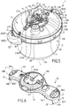
- the apparatus 1 comprises a lid subassembly (illustrated in isolation by the figure 4 ) which includes both the cover 3 and a support 10 attached to said cover 3, in this case permanently, so that the latter can pivot relative to said support 10, preferably between two positions respectively corresponding to the species to an unlocking configuration and a locking configuration of said lid subset.
- said lid sub-assembly is independent of the tank 2, so that it can be freely manipulated and moved independently of the tank 2.
- said subset is advantageously not attached or connected to the tank 2 permanently (which means in particular that the lid subassembly and the tank 2 are not connected by a hinge or other mechanical connection).
- the lid subassembly can therefore be freely manipulated and moved by a user, independently of the tank 2, in a free path.
- said independent lid subassembly rests freely against the tank 2 (and in this case on the tank 2) when said subset of lid and tank 2 are associated according to said second arrangement, which corresponds advantageously to the lock waiting configuration.
- the lid sub-assembly is not attached to the vessel 2 (in particular by a hinge or any hinge).
- the apparatus 1 comprises at least one guiding pin 18, and preferably two guiding pins 18, 19 arranged diametrically opposite relative to the central axis XX 'and attached to the lid 3 permanently (for example by being welded to the latter so as to rise vertically from the outer surface of said lid 3, in this case at the periphery of the latter, as illustrated in the figures).
- Each of said guide pins 18, 19 is designed to slide in a complementary elongate guide groove 18A, 19A formed in the support 10, for example towards each end of said support 10.
- the length of each groove 18A, 19A is adapted in this case to the angular travel of the cover 3 relative to the support 10.
- Each pin 18, 19 is further provided with an enlarged section head which cooperates with the edges of the corresponding groove 18A, 19A to vertically retain the support 10 and prevent it from moving vertically away from the lid 3.
- the lid subassembly thus forms an independent unitary element intended to be associated with the tank subassembly formed by the tank 2 itself and the bowl handles 2D, 2E, to form the cooking chamber.
- said lid subassembly also includes a seal (not shown) which advantageously has an annular shape and which is preferably carried by the lid 3. Said seal is intended to be interposed between the lid 3 and the tank 2 when the lid 3 is locked relative to the tank 2 to seal the cooking chamber.
- the support 10 is attached to said cover 3 so that the latter can pivot relative to said support 10 according to said central vertical axis X-X '.
- the pivot connection between the cover 3 and the support 10 can be achieved by any means known to those skilled in the art.
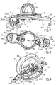
- said subset of cover and tank 2 are designed to be associated in at least a first arrangement (illustrated in FIGS. Figures 10 to 13 ) according to which the lid 3 overcomes the tank 2, that is to say is above and substantially to the right of the tank 2, preferably so as to extend substantially parallel to the bottom 2A of the tank 2, so that said first series of protuberances 7A-7J is substantially higher than said second series of excrescences 8A-8J.
- This first arrangement is a pre-docking arrangement, in which there is temporarily, and even fleetingly, the lid subassembly and the tank 2 when the lid subassembly is being reported by a user on the tank 2 to thereby close the tank 2 to form a sealed cooking chamber.
- the lid 3 is located above the tank 2, kept at a distance from the latter 2 by the user who is manually feeding the lid subassembly onto the tank 2.
- the weight of the sub the cover assembly is therefore not yet exerted on the vessel 2 and said first series of excrescences 7A-7J has not yet passed through the notches 9A-9J.
- the first arrangement therefore corresponds to an unstable positioning of the lid subassembly relative to the tank 2 which occurs momentarily on the trajectory followed by the lid subassembly when it is being fed towards the tank 2 to form the cooking chamber.
- the altitude (measured for example along the central vertical axis X-X ', from the bottom 2A of the tank 2) of the first series of protuberances 7A-7J carried by the lid 3 is therefore substantially greater than that of the second series of protuberances 8A-8J carried by the tank 2.
- said subset of cover and tank 2 are also designed to be associated in a second arrangement, obtained from said first arrangement referred to above by a downward movement (that is to say in this case vertical displacement from top to bottom, said displacement preferably not including rotation) of said lid subset until said first series of protuberances 7A-7J carried by the lid 3 are substantially lower than said second series of protuberances 8A-8J carried by the tank 2.
- the second arrangement therefore forms a pre-locking arrangement (corresponding to the pre-locking configuration of the apparatus 1 mentioned above), from which it is possible to lock the lid 3 relative to the tank 2 by simply pivoting the cover 3 relative to the support 10 and the tank 2.
- the second arrangement therefore allows the pivoting of the cover 3 relative to the support 10 for bringing said first series of excrescences 7A-7J under said second series of excrescences 8A-8J in lock match.
- the cover ramps formed by the first series of excrescences 7A-7J
- the series of notches 9A-9J so that the downward movement leading to the second arrangement allows each cover outgrowth 7A-7J to pass through a corresponding notch 9A-9J to end up at an altitude substantially lower than that of the protuberances 8A-8J forming the vessel ramps.
- said subassemblies lid and tank assembly 2 are designed so that when they are associated according to said second arrangement, the lid subassembly rests directly against the tank 2, in this case via the seal carried by the cover 3, which is found interposed between the upper free edge 2C and the lid 3.
- the second arrangement is therefore advantageously a stable arrangement of pre-lock ge, according to which the lid subassembly rests in equilibrium on and against the free upper edge 2C of the tank 2 (the user then no longer exerts any manual lifting effort of the lid subassembly).
- the downward movement is a displacement in translation parallel to said central vertical axis X-X ', that is to say that to go from the first arrangement to the second arrangement the vertically slidable lid subassembly , in a rectilinear trajectory, towards the bottom 2A of the tank 2, while the latter remains stationary.
- the tank 2 is locally surrounded by the second free annular edge 31B when said subset of cover and tank 2 are associated according to said second arrangement.
- the annular belt 3B is positioned substantially concentrically to the side wall 2B of the vessel 2, so as to surround the free end portion thereof, including at least the free upper edge 2C.
- said second free annular edge 31B is higher than the tank 2, as is apparent particularly from the Figures 11 to 13 , and therefore does not surround said tank 2.
- the second annular edge free 31B is at an altitude substantially greater than the altitude of the free upper edge 2C of the tank 2, the downward movement to move from the first to the second arrangement of lowering the annular belt 3B so that the second free annular edge 31B is found at an altitude lower than that of the free upper edge 2C of the tank 2, this relative positioning corresponding to the second arrangement.
- said support 10 and tank 2 are respectively provided with a first guide element 10 ', 10 "and second guide element 2', 2" complementary designed to collaborate as soon as said lid subassembly and the tank 2 are associated according to said first arrangement, for guiding said lid subassembly in its downward movement mentioned above, to move from the first arrangement to the second arrangement.
- the first and second complementary guide elements 10 ', 10 ", 2', 2" are therefore designed to be in a specific relative position, when the lid subassembly and the tank 2 are associated according to the first arrangement, which provides a function of assisting the positioning of the support 10 and the tank 2, to guide the lid subset in its downward movement leading to the second arrangement.
- the first guide element 10 ', 10 "mechanically interacts with the second complementary guide element 2', 2" to assist the user. placing the support 10 and the vessel 2 in a predetermined relative position from which said subset of the lid and the vessel 2 can reach their second arrangement by simply approaching each other in pure translation parallel to the central vertical axis XX 'of the support 10 and the tank 2.
- the lid subassembly is guided early in its downhill path vertical to the tank 2 to cap the latter in the second arrangement, that is to say it is guided even before the cover ramps interact in one way or another with the annular flange which protrudes outwardly from the free upper edge 2C to form the tubular ramps 8A-8J and the passage notches 9A-9J.
- This feature greatly facilitates the proper positioning of the lid 3 relative to the tank 2, avoiding having to resort to several attempts, " blindly ", unlike prior art devices with which it is common that the user reports the lid 3 relative to the tank 2 in an incorrect orientation that does not allow the direct passage, at the first attempt, the cover ramps 7A-7J through the passage notches 9A-9J.
- the invention has thus made it possible to establish that the implementation of a prior guidance, which begins to take place not when the first series of excrescences 7A-7J is substantially at the same height or lower than the second series of excrescences 8A-8J, but although said first series of excrescences 7A-7J is still at an altitude greater than that of said second series the protuberances 8A-8J, contributes to confer a particularly ergonomic and practical character to the pressure cooker 1.
- said first complementary guiding element 10 ', 10 "and second guiding element 2', 2" are designed to substantially continuously guide the lid subset in its downward movement until said second arrangement is obtained.
- said complementary first and second guide members 10 ', 10 ", 2', 2" interact with each other over the entire trajectory of the lid subassembly during the downward movement of the lid subassembly, in order to prevent said subassembly from underlining.
- cover assembly does not completely leave said path, for example by shifting angularly in the horizontal plane perpendicular to the central vertical axis XX 'or in a vertical plane parallel to said central vertical axis X-X', or by shifting axially by translation horizontal.
- the said first and complementary second guiding elements 10 ', 10 ", 2', 2" collaborate as soon as said lid and tank subassemblies 2 are associated according to the first arrangement and continue their collaboration of guiding and positioning aid at least until to obtaining the second arrangement.
- said collaboration of said first and second guide elements 10 ', 10 ", 2', 2" for guiding said lid subset in its downward movement between the first arrangement and the second arrangement is a male / female type collaboration, resting on the insertion of all or part of a male portion, that is to say of a portion having a substantially convex surface, in a female portion, that is to say a portion having a concave surface , to carry out a guide, by facing the male and female portions.
- Said male / female cooperation rests for example on a mutual interlocking of said first and second guide elements 10 ', 10 ", 2', 2".
- said first and second guide elements 10 ', 10 ", 2', 2" respectively have a male conformation which advantageously has a curved profile and a female conformation which advantageously has a curved profile conjugated to said curved profile, said conformation male and female conformation are thus complementary.
- the second guide element 2 ', 2 "which has a male conformation and the first guide element 10', 10 "which has a female conformation are instead the second guide element 2 ', 2 "which has a male conformation and the first guide element 10', 10 "which has a female conformation.
- the second guide element 2 ', 2 " is carried by said bowl handle 2D, 2E
- the vessel 2 is provided with two second guide elements 2', 2" arranged diametrically opposed to the central vertical axis X-X '.
- Said second guiding elements 2 ', 2 "thus form two female conformations which are fixed on the external face of the side wall 2B of the tank 2 and which are advantageously carried respectively by the two bowl handles 2D, 2E, and even more
- the support 10 projects more radially from the cover 3 to which it is attached, to form said first guide element 10 ', 10 ".
- the support 10 extends substantially beyond the periphery of the cover 3 according to the radial direction Y-Y ', so that said first guide member 10', 10 "protrudes laterally from the lid 3, and thus forms a radial protuberance at the periphery of the lid 3.
- the support 10 comprises an upper portion 100 , 101, 102 which is mounted above the cover 3, for example on and against the outer face of the discoid cover member 3A and which protrudes radially from the latter to extend by a vertical falling edge 10A, 10B which carries said first guide element 10 ', 10 ", and which even more preferably forms said male conformation of said guide element 10', 10" in question, said falling edge 10A, 10B extends in this case locally facing annular belt 3B, substantially parallel to the latter.
- the vertical falling edge 10A, 10B advantageously has a curved shape for locally following the circular contour of the annular belt 3B.
- the support 10 is, in the embodiment illustrated in the figures, in the form of a cross member, that is to say a substantially elongate piece which extends diametrically on the cover 3 and which is extended in this case at each of its ends by two respective falling edges 10A, 10B respectively forming two first guide members 10 ', 10 "arranged diametrically opposite to the central vertical axis X-X'.
- the cross-piece in question comprises an enlarged central zone 100, for example of generally circular shape, extended on either side by a first arm 101 and a second arm 102 which themselves respectively terminate in said falling edges 10A, 10B
- the central portion 100 is advantageously provided with a central orifice in which is intended to be threaded an axis 30 fixed on the lid 3, in the center of the latter, and around which the support 10 is intended to rotate. r along the central vertical axis X-X '.
- the axis 30 is for example welded to the cover 3 so as to rise vertically from the center of the latter, and thus to be inserted into said hole 100A.
- the axis 30 is provided with a threaded recess for cooperating with a screw 16 in order to fix the support 10 to the cover 3 while allowing the cover 3 to pivot about the axis 30.
- the support 10 includes, in addition to the cross-piece shown at figure 6 , a plate 17 which has a generally circular shape substantially complementary to that of the central portion 100 of the cross member and which is intended to be interposed between said cross member and the upper face of the cover 3 to form a housing intended to accommodate at least partly a mechanism for controlling the pivoting of the cover 3 relative to the support 10 which will be described more in detail below.
- the plate 17 is in the form of a plastic cup provided with a central orifice, which is extended by a vertical cylindrical tube within which is intended to be inserted the axis 30.
- the visible crossbar at the figure 6 is itself designed to be fixed (for example by means of several screws) permanently to the plate 17, in order to form with the latter a subassembly unitary cross member, monobloc, held on the cover 3 by means of the Coupling axis 30 / screw 16, which coupling allows the pivoting of the lid 3 relative to the superstructure subassembly mentioned in this case the support 10.
- the female conformation of the second guide element 2 ', 2 forms a housing 20D, 20E intended to gradually accommodate the first guide element 10', 10" as the lid subassembly descends towards the vessel 2 to go from the first arrangement to the second arrangement.
- Said housing 20D, 20E is advantageously delimited by at least one bottom 20D ', 20E', which is preferably substantially horizontal, and from which extends vertically a side wall 20D “, 20E” between a lower edge 201D ", 201E “and an upper edge 202D", 202E ".
- Said housing 20D, 20E is advantageously intended to accommodate within it, by vertical downward insertion, said male conformation of the first guide element 10 ', 10 "formed in this case by the falling vertical edge 10A, 10B.
- 20D “, 20E” of said housing 20D ', 20E' is substantially vertically, substantially parallel to the side wall 2B of the vessel 2, and has a substantially curved profile so as to form a concavity arranged facing the side wall 2B
- the shape of this concavity is substantially conjugated, as previously stated, to the convex shape of the vertical falling edge 10A, 10B forming the first guide element 10 ', 10 ".
- said male conformation of the first guide element 10 ', 10 "extends vertically between an upper edge 10A', 10B 'and a lower edge 10A", 10B "respectively corresponding to the species at the high and low ends of the vertical falling edge 10A, 10B coming from the support 10.
- said male conformation is inserted in said housing 20D, 20E so that the lower edge 10A ", 10B" of the male conformation is found lower than the upper edge 202D “, 202E” of the side wall 20D “, 20E” of said housing 20D, 20E and is separated vertically from the bottom 20D ', 20E' of the housing 20D, 20E by a first height H1.
- said male conformation is inserted into the housing 20D, 20E so that the lower edge 10A ", 10B" of the male conformation is lower. that the upper edge 202D “, 202E” of said side wall 20D “, 20E” of said housing 20D, 20E and is separated vertically from the bottom 20D ', 20E' of the housing 20D, 20E by a second height H2 less than said first height H1 .
- said second height H2 is non-zero, that is to say that the male conformation does not come into contact with the bottom 20D ', 20E' when the lid subassembly and the tank 2 are associated according to said second arrangement.
- said lid and bowl subassemblies 2 are designed so that when they are associated according to the second arrangement, the lid subassembly rests directly against the bowl 2 so as to maintain a vertical spacing (corresponding to the non-zero distance H2) between said first and second guide elements 10 ', 10 ", 2', 2", so that said first guide element 10 ', 10 "does not exert vertical support on said second element of 2 ', 2 "guide.
- the cooperation between said first guide element 10 ', 10 "and second guide element 2', 2" is therefore advantageously only a positioning and guiding cooperation, and not a support cooperation of a guide element by the other .
- said housing 20D, 20E is carried by the handle 2D, 2E, and is preferably directly formed by said handle 2D, 2E.
- said handle 2D, 2E comprises a gripping portion 200D, 200E which is shaped so that it can be grasped manually in order to allow the manipulation of the tank 2 through it.
- the said gripping portion 200D, 200E has a shape that makes it adapted to be caught by hand by a user to lift or carry the tank 2.
- said handle 2D, 2E also includes a fastening portion 201D, 201E which connects said tank 2 and gripping portion 200D, 200E.
- the fastening portion 201D, 201E extends radially outwardly of the side wall 2B of the tank 2, and supports the corresponding gripping portion 200D, 200E.
- said housing 20D, 20E is delimited (i) vertically by the fixing portion 201D, 201E, which advantageously forms the bottom 20D ', 20E' of the housing 20D, 20E and (ii) laterally by the gripping portion 200D , 200E which in this case forms said side wall 20D ", 20E" of said housing 20D, 20E.
- the apparatus 1 further comprises a first positioning element 12, 13 which is carried by the support 10 and which is designed to interact mechanically, when said lid subassembly and the tank 2 are associated according to said second arrangement, with a second complementary positioning element 14, 15 carried by the tank 2, and preferably by the 2D handle, 2E tank, to lock the relative angular positioning of the support 10 and the tank 2 in a horizontal plane (which is in this case perpendicular to said central vertical axis X-X ').
- This mechanical interaction makes it possible to prevent the support 10 from being able to pivot relative to the tank 2, in this case along said central vertical axis X-X ', when the lid subassembly and the tank 2 are united according to said second arrangement. pre-locking.
- the combination of the lid subassembly and the tank 2 according to said second arrangement causes interlocking of the support 10 and the tank 2, by cooperation of said first positioning element 12, 13 and second positioning element 14, 15, in order to obtain a locking of the relative angular position of the support 10 and the tank 2.
- This angular locking in the horizontal plane allows the support 10 to act as a stationary fixed frame relative to the vessel 2 and with respect to which the lid 3 can pivot about the central vertical axis XX 'according to said predetermined angular stroke (which is for example of the order of 15 °) to go from an unlocked state (illustrated in FIG. figure 1 ) to a locked state (shown in figure 16 ).
- said mechanical interaction of said first positioning element 12, 13 with said second positioning element 14, 15 is a male / female cooperation, based on the insertion of all or part of a male portion into a female portion to achieve a mechanical locking of angular locking.
- Said male / female cooperation rests for example on a mutual engagement of said first positioning element 12, 13 and second positioning element 14, 15.
- the first and second positioning elements 12, 13, 14, 15 respectively have a female conformation and a complementary male conformation.
- the first positioning element 12, 13 to have a male conformation while the second positioning element 14, 15 has a conformation. female.
- the vessel 2 is provided with two male tank formations 14, 15 arranged diametrically opposite to the central vertical axis XX 'and fixed on the external face of the side wall 2B of the tank 2, while the support 10 has two complementary female support conformations 12, 13 arranged diametrically opposite on the cover 3 relative to the central vertical axis X-X ', said female support formations 12, 13 being species disposed facing the outer face of the annular belt 3B of the cover 3.
- said support 10 and tank 2 are filled respectively a single support and vessel conformation, or even that the support 10 and tank 2 are provided, instead of male / female conformations intended to cooperate by interlocking, elements Interlocking of another nature based on the implementation of a force cooperation (friction, clipping, meshing, magnetic attraction ...) sufficient to lock the relative angular position of the support 10 and the vessel 2.
- said first positioning element 12, 13 is formed by a notch formed in the vertical falling edge 10A, 10B, while said second positioning element 14, 15 is formed by a rib advantageously arranged in the said housing 20D, 20E.
- said rib is preferably carried by the handle 2D, 2E, and even more preferably is an integral part of the latter.
- each handle 2D, 2E is permanently fixed to the side wall 2B of the tank 2 and embeds a respective male conformation, which is for example in the form of a rib that advantageously comes from material with the handle 2D, corresponding 2E.
- said rib rises vertically from the bottom 20D ', 20E' of the housing 20D, 20E and protrudes radially inwardly from the side wall 20D ", 20E", as illustrated in the figures.
- the support 10 is advantageously in the form of a cross member which extends on the cover 3 (being connected thereto by a pivot connection) and which is extended at each of its ends by respective vertical falling edges 10A, 10B, which protrude radially from the cover 3 and extend substantially parallel to the annular belt 3B, outside thereof.
- a notch is advantageously formed in the free lower edge 10A ", 10B" of each of said falling edges 10A, 10B of the support 10, to form a female conformation complementary to the rib preferably forming the male conformation.
- the apparatus 1 further advantageously comprises a control member 11 of the bayonet locking system, designed in this case to be manually movable relative to the support 10, so as to allow the user to control the locking / unlocking of the cover 3 relative to the tank 2, that is to say the passage of the device 1 from its pre-locking configuration (also called locking waiting configuration - illustrated in FIG. figure 1 ) to its lock configuration (shown in figure 16 ), and vice versa, by rotating the lid 3 relative to the support 10 and the tank 2.
- the control member 11 is advantageously carried by the support 10, in this case permanently, so that it makes part of said lid subset.
- the control member 11 is mounted on the support 10 so as to be manually movable relative to the latter between locking positions ( figure 16 ) and unlocking ( figure 1 ).
- control member 11 is advantageously fixed permanently to the support 10 while maintaining a mobility ability relative to the latter, so that a user can drive manually the control member 11 relative to the support 10 from the unlocking position to the locking position and vice versa.
- apparatus 1 advantageously comprises a device for transforming said manual displacement of the control member 11 by pivoting the lid 3 relative to the support 10.
- the transformation device which is in particular visible to the figures 5 , 9 , 18 , 20 and 21 , is therefore designed to convert the movement of the control member 11 relative to the support 10 in rotary motion of the cover 3 relative to the same support 10, in this case along said central vertical axis!
- the aforementioned conversion device is designed according to the nature of the displacement of the control member 11 relative to the support 10 and may implement any drive component (toothed wheel, cam, lever, rod, etc.. ) required.
- the implementation of a control member 11 embedded on the support 10 and mounted movably relative to the latter is however perfectly optional.
- control member 11 it is conceivable, without departing from the scope of the invention, for the control member 11 to be formed by a simple fixed handle attached directly to the cover 3 and separate from the support 10, in which case the setting implementation of a transformation device is not necessary.
- the use of a control member 11 embedded on the support 10 and mounted movably relative to the latter is however preferred, because it facilitates the use of the apparatus 1.
- the invention is absolutely not limited to the implementation of a specific mechanical connection connecting the control member 11 and the support 10.
- the control member 11 can thus be mounted pivotally and / or translationally relative to the support 10, by any appropriate means .
- control member 11 can be mounted with pure rotation around an axis of rotation which extends in a direction intersecting with the direction of the central vertical axis X-X ', and even more preferably along an axis of rotation secant to the central vertical axis X-X ', or alternatively be mounted in translation relative to the support 10, for example vertical sliding (preferably according to a sliding axis coincides with the central vertical axis X-X ') relative to said support 10, or else be connected to the support 10 by a mechanical link combining a translation and a rotation (for example a helical connection of axis X-X ').
- the control member 11 can thus be in the form of a rotary member of the handle, lever, handle, handle ...
- control member 11 is pivotally mounted relative to said support 10 according to a radial axis YY 'pivoting which is perpendicular to the central vertical axis X-X', and is preferably secant to this last.
- said transformation device comprises a gear reduction mechanism designed to drive the cover 3 in rotation about said central vertical axis X-X ', in a race having a first predetermined angular amplitude a, in response to a rotation of said control member 11 around said radial axis YY 'in a race having a second predetermined angular amplitude ⁇ greater than said first predetermined angular amplitude a.
- the control member 11 is designed to pivot about said radial axis YY 'between a raised position (corresponding to the unlocking) and a folded position (corresponding to the lock) separated by a stroke having a predetermined angular amplitude ⁇ of approximately 90 °, while the lid 3 pivots relative to the support 10, in response to the angular displacement of about 90 ° of the control member 11 relative to the support 10, in a path having a predetermined angular amplitude ⁇ of about 15 ° .
- the transformation device comprises a transmission part 20 mounted to move in translation in a horizontal plane perpendicular to said central vertical axis XX 'relative to said support 10.
- the transformation device comprises a mechanism for transforming the pivoting movement of the organ 11 relative to the support 10 in translational movement of said transmission member 20 relative to said support 10.
- the transformation mechanism in question is formed by a cam 110, 111 integral with the control member 11, said cam 110, 111 being provided a pin which is received in a corresponding housing formed in the transmission part 20, so that the pivoting of the control member 11 causes the concomitant pivoting of the cam 110, 111, which then pushes the transmission piece 20 in the horizontal plane perpendicular to the central vertical axis X-X '.
- the transformation device comprises, in accordance with the embodiment illustrated in the figures, at least one horizontal lever 21 pivotally mounted relative to the support 10 according to an eccentric vertical axis ZZ 'which is fixed with respect to said support 10, parallel to said vertical axis central XX 'and located at a predetermined distance from the latter.
- said horizontal lever 21 extends longitudinally between a first end 21A hinged to the cover 3 and a second end 21B hinged either to said control member 11 or to a transmission part (such as for example the transmission 20 evoked above) which is part of the transformation device and which is driven in displacement relative to the support 10 by the control member 11, for example according to the embodiment described above.
- the horizontal lever 21 is provided with a housing (formed for example by a through hole) intended to accommodate an axis 22 secured to the support 10, and for example from the plate 17, so as to achieve a pivotal connection d ZZ 'axis between the horizontal lever 21 and the support 10.
- said horizontal lever 21 is pivotally mounted relative to the support 10 at a pivot point located between said first end 21A and second end 21B, so that the Eccentric vertical axis ZZ 'passes through an area of the horizontal lever 21 which is located at a distance from both the first and the second end 21A, 21B.
- the articulation of the first end 21A relative to the cover 3 is for example made by means of a first pin 210A which is integral with the cover 3, and which is for example welded to the outer face of said cover 3 so as to rise vertically from the latter.
- Said pin 210A is advantageously received in a first corresponding groove 211A formed at the first end 21A of the horizontal lever 21, so that said first pin 210A can both slide and turn in the first groove 211A in question.
- the conversion device also advantageously comprises a second pin 210B which is in this case secured to the transmission part 20 and embarked on the latter.
- Said second stud 210B is advantageously received in a second complementary groove 211B formed at the second end 21B of the horizontal lever 21, so that said second pin 210B can both slide and pivot in the second groove 211B in question.
- the horizontal lever 21 advantageously has an overall shape of a sickle, with a substantially rectilinear arm extending from the first end 21A to the point of rotation traversed by the eccentric vertical axis Z-Z ', and then continuing. by an arcuate portion to the second end 21B.
- control member 11 comprises a handle 11A to be manually actuated so that it can be moved manually by a user between two stop positions, respectively corresponding to the locking and unlocking.
- control member 11 is therefore in the form of an arched, loop-shaped, arched piece, advantageously designed to be grasped firmly, preferably by hand, by a user. .
- the control member 11 is advantageously designed so that its manual movement relative to the support 10 can be performed in either a locking direction or an opposite direction of unlocking.
- the control member 11 is mounted pivotally relative to said support 10 between on the one hand an extended position ( figure 1 ) corresponding to the unlocking of the cover 3 and wherein said control member 11 protrudes vertically, in this case to the right of the cover 3 to the outside, and on the other hand a retracted position which forms said locking position and in which said control member 11 is lowered towards the cover 3.
- control member 11 In its deployed position, the control member 11 advantageously extends in a mean direction substantially parallel to said central vertical axis X-X ', whereas in its retracted position it advantageously extends according to a mean direction substantially perpendicular to said central vertical axis X-X ', as shown in the figures.
- the operation of the cooking appliance 1 illustrated in the figures will now be briefly described.
- the user first fills the tank 2 illustrated in FIG. figure 2 of food to be cooked, possibly positioning the food away from the bottom of the tank 2, in a perforated cooking basket.
- the user then grabs the lid subassembly shown in figure 4 by the handle 11A for lifting said lid subassembly for the return to the tank 2 to cap the latter to form a sealed cooking chamber.
- the user first brings the lid subassembly above the tank 2, according to a relative positioning which corresponds to the first predetermined arrangement illustrated in FIGS. Figures 11 to 13 .
- the curved falling edges 10A, 10B of the support 10 begin to partially fit in the corresponding housings 20D, 20E, while the cover 3 is always held manually above the tank 2 against its weight.
- This cooperation of the vertical falling edges 10A, 10B with the corresponding housings 20D, 20E formed by the handles 2D, 2E of the tank 2 makes it possible to correctly position the lid 3 relative to the tank 2 in the horizontal plane, and to guide the vertical trajectory of the lid 3 relative to the tank 2 when the user then continues to lower the lid subassembly on the tank 2 to cover the latter and thus reach the second pre-locking arrangement, in which the ribs forming the second positioning elements 14, 15 are interlocked in the corresponding notches forming the first positioning elements 12, 13, thereby locking the relative angular positioning of the support 10 and the vessel 2 in a horizontal plane perpendicular to the vertical axis central X-X '.
- the apparatus 1 is then in a locking waiting configuration, from which it is possible, by simply rotating the lid 3 relative to the tank 2, to lock the lid 3 relative to the tank 2.
- the apparatus 1 User folds the handle 11A in an angular stroke ⁇ of about 90 °, until reaching a folded abutment position illustrated in particular to figures 16 and 17 .
- This manual movement of the handle 11A from its deployed position to its folded position concomitantly causes the pivoting of the lid 3 relative to the support 10 at an angle ⁇ of about 15 °, thus allowing the cover ramps 7A-7J to match under the tank ramps 8A-8J in a locking configuration for the pressure rise.
- the user At the end of the cooking cycle, and once the pressure within the chamber has fallen back to a predetermined safety level, the user only has to raise the handle 11A to rotate the cover 3 relative to the support 10 in the opposite direction and thus disengage the tank and lid ramps, allowing the separation of the lid 3 and the tank 2.
Landscapes
- Engineering & Computer Science (AREA)
- Food Science & Technology (AREA)
- Cookers (AREA)
Priority Applications (1)
| Application Number | Priority Date | Filing Date | Title |
|---|---|---|---|
| PL16171008T PL3100655T3 (pl) | 2015-06-02 | 2016-05-24 | Szybkowar bagnetowy wyposażony w elementy prowadzące |
Applications Claiming Priority (1)
| Application Number | Priority Date | Filing Date | Title |
|---|---|---|---|
| FR1555001A FR3036937A1 (fr) | 2015-06-02 | 2015-06-02 | Autocuiseur a baionnette pourvu d'elements de guidage |
Publications (2)
| Publication Number | Publication Date |
|---|---|
| EP3100655A1 EP3100655A1 (fr) | 2016-12-07 |
| EP3100655B1 true EP3100655B1 (fr) | 2018-03-21 |
Family
ID=54007857
Family Applications (1)
| Application Number | Title | Priority Date | Filing Date |
|---|---|---|---|
| EP16171008.2A Active EP3100655B1 (fr) | 2015-06-02 | 2016-05-24 | Autocuiseur à baionnette pourvu d'éléments de guidage |
Country Status (10)
| Country | Link |
|---|---|
| US (1) | US10244883B2 (pl) |
| EP (1) | EP3100655B1 (pl) |
| JP (1) | JP6783557B2 (pl) |
| KR (1) | KR102472986B1 (pl) |
| CN (2) | CN106213984B (pl) |
| BR (1) | BR102016012399B1 (pl) |
| ES (1) | ES2670038T3 (pl) |
| FR (1) | FR3036937A1 (pl) |
| PL (1) | PL3100655T3 (pl) |
| PT (1) | PT3100655T (pl) |
Families Citing this family (19)
| Publication number | Priority date | Publication date | Assignee | Title |
|---|---|---|---|---|
| FR3036937A1 (fr) * | 2015-06-02 | 2016-12-09 | Seb Sa | Autocuiseur a baionnette pourvu d'elements de guidage |
| EP3638543B1 (en) * | 2017-06-30 | 2021-06-02 | SMR Patents S.à.r.l. | Rearview device with moveable head assembly and vehicle therewith |
| CN110123159A (zh) | 2017-08-09 | 2019-08-16 | 沙克忍者运营有限责任公司 | 烹饪系统 |
| CN109124329B (zh) * | 2017-08-10 | 2025-06-27 | 武汉苏泊尔炊具有限公司 | 压力锅 |
| CN109892966B (zh) * | 2017-12-12 | 2024-02-02 | 佛山市顺德区美的电热电器制造有限公司 | 盖体及烹饪器具 |
| USD914436S1 (en) | 2018-06-19 | 2021-03-30 | Sharkninja Operating Llc | Air diffuser with food preparation pot |
| FR3082717B1 (fr) * | 2018-06-26 | 2020-07-03 | Seb S.A. | Autocuiseur muni d'une butee pour couvercle |
| USD934027S1 (en) | 2018-08-09 | 2021-10-26 | Sharkninja Operating Llc | Reversible cooking rack |
| USD883014S1 (en) | 2018-08-09 | 2020-05-05 | Sharkninja Operating Llc | Food preparation device |
| USD903413S1 (en) | 2018-08-09 | 2020-12-01 | Sharkninja Operating Llc | Cooking basket |
| USD883015S1 (en) | 2018-08-09 | 2020-05-05 | Sharkninja Operating Llc | Food preparation device and parts thereof |
| US20190254476A1 (en) | 2019-02-25 | 2019-08-22 | Sharkninja Operating Llc | Cooking device and components thereof |
| CN212788226U (zh) | 2019-02-25 | 2021-03-26 | 沙克忍者运营有限责任公司 | 烹饪系统 |
| USD918654S1 (en) | 2019-06-06 | 2021-05-11 | Sharkninja Operating Llc | Grill plate |
| USD982375S1 (en) | 2019-06-06 | 2023-04-04 | Sharkninja Operating Llc | Food preparation device |
| CN110421643B (zh) * | 2019-07-10 | 2024-05-28 | 杭州中亚机械股份有限公司 | 一种切割装置 |
| US11647861B2 (en) | 2020-03-30 | 2023-05-16 | Sharkninja Operating Llc | Cooking device and components thereof |
| FR3117757B1 (fr) * | 2020-12-18 | 2023-04-21 | Seb Sa | Autocuiseur a baionnette pourvu d’un module de commande |
| USD1114552S1 (en) | 2023-10-09 | 2026-02-24 | Lagom Kitchen Co. | Cookware appliance or cookware |
Family Cites Families (31)
| Publication number | Priority date | Publication date | Assignee | Title |
|---|---|---|---|---|
| US2600703A (en) * | 1946-05-18 | 1952-06-17 | Speed Meal Corp | Pressure cooker |
| CH298375A (de) | 1948-11-26 | 1954-04-30 | Keller Max | Druckkocher. |
| GB657982A (en) | 1949-04-29 | 1951-10-03 | Midland Metal Spinning Company | Pressure cookers |
| US2583085A (en) * | 1949-09-21 | 1952-01-22 | John F Campbell | Flexible sleeve type vulcanizing apparatus for v belts and the like |
| US3653533A (en) * | 1969-10-24 | 1972-04-04 | Peder Mortensen | Door assembly |
| US3876385A (en) * | 1972-07-31 | 1975-04-08 | Johns Manville | Fail-safe system for operating an autoclave door |
| CH571335A5 (en) | 1972-11-28 | 1976-01-15 | Tanner Willy | Pressure cooker with bayonet type lid fixing - prevents excessive pressure by allowing local deflection of sealing ring |
| BR8601076A (pt) * | 1986-03-13 | 1987-10-27 | Alcan Brasil | Recipiente para preparacao de conservas de alimentos |
| IT1227311B (it) * | 1988-10-10 | 1991-04-05 | Lagostina Spa | Sistema di chiusura per pentola a pressione |
| KR0128775Y1 (ko) * | 1995-12-07 | 1998-10-15 | 문무영 | 전기압력솥의 압력뚜껑 자동 개폐로크장치 |
| FR2783687B1 (fr) | 1998-09-28 | 2000-11-17 | Seb Sa | Dispositif de verrouillage/deverrouillage d'un appareil de cuisson sous pression a fermeture a baionnettes |
| CN2389593Y (zh) | 1999-09-09 | 2000-08-02 | 周赛方 | 压力锅 |
| FR2802400B1 (fr) * | 1999-12-15 | 2002-07-12 | Seb Sa | Appareil de cuisson sous pression a poignees amovibles |
| CH694356A5 (de) | 2000-09-27 | 2004-12-15 | Marlene Hurni | Dampfkochtopf für Linkshänder. |
| CN2469839Y (zh) | 2001-03-30 | 2002-01-09 | 简伟文 | 多功能电热锅 |
| JP4649424B2 (ja) * | 2006-05-17 | 2011-03-09 | パナソニック株式会社 | 炊飯器 |
| CN201404063Y (zh) * | 2009-05-06 | 2010-02-17 | 上海奔腾企业(集团)有限公司 | 电压力锅上盖防漏装限位装置 |
| CH701207A1 (de) | 2009-06-02 | 2010-12-15 | Kuhn Rikon Ag | Schnellkochtopf. |
| CN101606821A (zh) * | 2009-07-03 | 2009-12-23 | 佛山市富士宝电器科技股份有限公司 | 电压力锅的锅盖结构 |
| CN201523971U (zh) * | 2009-11-30 | 2010-07-14 | 东莞市步步高家用电器有限公司 | 合盖到位与定时开关互锁的电压力锅 |
| CN201624512U (zh) * | 2010-03-30 | 2010-11-10 | 黄振雄 | 一种连体式电压力锅 |
| CN103930007B (zh) | 2011-09-15 | 2016-04-13 | 金雨龙 | 不具有橡胶衬垫的电饭压力锅和压力锅 |
| US9756979B2 (en) * | 2011-10-07 | 2017-09-12 | All-Clad Metalcrafters Llc | Pot with bail handle and tiltable lid |
| CN102349791B (zh) * | 2011-10-12 | 2014-04-02 | 中山市雅乐思电器实业有限公司 | 一种侧翻盖压力锅 |
| CN202287775U (zh) * | 2011-10-20 | 2012-07-04 | 浙江苏泊尔股份有限公司 | 压力锅开合盖装置 |
| CN102423236B (zh) * | 2011-11-17 | 2016-05-04 | 美的集团股份有限公司 | 用于微波炉的饭煲 |
| JP3174577U (ja) * | 2012-01-16 | 2012-03-29 | 浙江永▲達▼工貿有限公司 | 圧力調理容器の蓋体開閉構造 |
| CN202681623U (zh) * | 2012-07-12 | 2013-01-23 | 中山市雅乐思电器实业有限公司 | 一种旋转后翻盖的压力锅 |
| FR2998152B1 (fr) | 2012-11-16 | 2017-11-24 | Seb Sa | Appareil de cuisson d'aliments sous pression comportant un organe de commande ameliore |
| CN203000535U (zh) * | 2013-01-15 | 2013-06-19 | 广东创迪电器有限公司 | 一种锅盖拆装方便的电压力锅 |
| FR3036937A1 (fr) * | 2015-06-02 | 2016-12-09 | Seb Sa | Autocuiseur a baionnette pourvu d'elements de guidage |
-
2015
- 2015-06-02 FR FR1555001A patent/FR3036937A1/fr not_active Ceased
-
2016
- 2016-05-24 PT PT161710082T patent/PT3100655T/pt unknown
- 2016-05-24 ES ES16171008.2T patent/ES2670038T3/es active Active
- 2016-05-24 EP EP16171008.2A patent/EP3100655B1/fr active Active
- 2016-05-24 PL PL16171008T patent/PL3100655T3/pl unknown
- 2016-05-31 BR BR102016012399-2A patent/BR102016012399B1/pt active IP Right Grant
- 2016-06-01 JP JP2016110174A patent/JP6783557B2/ja active Active
- 2016-06-01 KR KR1020160067972A patent/KR102472986B1/ko active Active
- 2016-06-02 US US15/172,048 patent/US10244883B2/en active Active
- 2016-06-02 CN CN201610387751.2A patent/CN106213984B/zh active Active
- 2016-06-02 CN CN201620527121.6U patent/CN206342327U/zh active Active
Non-Patent Citations (1)
| Title |
|---|
| None * |
Also Published As
| Publication number | Publication date |
|---|---|
| JP2016221290A (ja) | 2016-12-28 |
| CN106213984B (zh) | 2022-04-08 |
| US20160353915A1 (en) | 2016-12-08 |
| FR3036937A1 (fr) | 2016-12-09 |
| KR20160142245A (ko) | 2016-12-12 |
| JP6783557B2 (ja) | 2020-11-11 |
| ES2670038T3 (es) | 2018-05-29 |
| BR102016012399B1 (pt) | 2022-02-15 |
| CN206342327U (zh) | 2017-07-21 |
| EP3100655A1 (fr) | 2016-12-07 |
| PT3100655T (pt) | 2018-05-23 |
| PL3100655T3 (pl) | 2018-08-31 |
| KR102472986B1 (ko) | 2022-12-02 |
| BR102016012399A2 (pt) | 2016-12-06 |
| US10244883B2 (en) | 2019-04-02 |
| CN106213984A (zh) | 2016-12-14 |
Similar Documents
| Publication | Publication Date | Title |
|---|---|---|
| EP3100655B1 (fr) | Autocuiseur à baionnette pourvu d'éléments de guidage | |
| EP3100653B1 (fr) | Autocuiseur a baionnette pourvu d'un organe de commande | |
| EP3100652B1 (fr) | Autocuiseur pourvu d'un organe de commande manuel du verrouillage | |
| FR3036936B1 (fr) | Autocuiseur a baionnette pourvu d'une poignee de cuve | |
| EP3072423B1 (fr) | Autocuiseur a baionnette et procede de fabrication afferent | |
| EP2732736B1 (fr) | Appareil de cuisson d'aliments sous pression comportant un organe de commande amélioré | |
| EP3329810B1 (fr) | Autocuiseur a baionnette et verrou mobile | |
| EP3461379B1 (fr) | Autocuiseur a baionnette et procede de fabrication afferent | |
| EP3100656B1 (fr) | Autocuiseur équipé d'un support et d'un couvercle mobile relativement audit support | |
| EP3586689B1 (fr) | Autocuiseur muni d'une butee pour couvercle | |
| EP2937026B1 (fr) | Appareil de cuisson sous pression a organe de commande manuel relevable | |
| EP2478801A1 (fr) | Appareil de cuisson sous pression à organe de commande du verrouillage / déverrouillage bi-fonctionnel | |
| EP3329809B1 (fr) | Autocuiseur à baionnette à poignées de cuve et de couvercle interverrouillables | |
| EP2624728A1 (fr) | Appareil de cuisson sous pression a organe de commande debrayable | |
| WO2008102073A1 (fr) | Appareil de cuisson sous pression muni d'un verrou | |
| EP3100657A1 (fr) | Autocuiseur pourvu d'une soupape démontable et d'un capteur de température | |
| EP2716188B1 (fr) | Appareil de cuisson d'aliments sous pression a couvercle allege | |
| EP4014795B1 (fr) | Autocuiseur à baionnette pourvu d'un organe de commande au comportement dynamique amélioré |
Legal Events
| Date | Code | Title | Description |
|---|---|---|---|
| PUAI | Public reference made under article 153(3) epc to a published international application that has entered the european phase |
Free format text: ORIGINAL CODE: 0009012 |
|
| AK | Designated contracting states |
Kind code of ref document: A1 Designated state(s): AL AT BE BG CH CY CZ DE DK EE ES FI FR GB GR HR HU IE IS IT LI LT LU LV MC MK MT NL NO PL PT RO RS SE SI SK SM TR |
|
| AX | Request for extension of the european patent |
Extension state: BA ME |
|
| 17P | Request for examination filed |
Effective date: 20170607 |
|
| RBV | Designated contracting states (corrected) |
Designated state(s): AL AT BE BG CH CY CZ DE DK EE ES FI FR GB GR HR HU IE IS IT LI LT LU LV MC MK MT NL NO PL PT RO RS SE SI SK SM TR |
|
| GRAP | Despatch of communication of intention to grant a patent |
Free format text: ORIGINAL CODE: EPIDOSNIGR1 |
|
| INTG | Intention to grant announced |
Effective date: 20171011 |
|
| GRAS | Grant fee paid |
Free format text: ORIGINAL CODE: EPIDOSNIGR3 |
|
| GRAA | (expected) grant |
Free format text: ORIGINAL CODE: 0009210 |
|
| AK | Designated contracting states |
Kind code of ref document: B1 Designated state(s): AL AT BE BG CH CY CZ DE DK EE ES FI FR GB GR HR HU IE IS IT LI LT LU LV MC MK MT NL NO PL PT RO RS SE SI SK SM TR |
|
| REG | Reference to a national code |
Ref country code: GB Ref legal event code: FG4D Free format text: NOT ENGLISH |
|
| REG | Reference to a national code |
Ref country code: CH Ref legal event code: EP |
|
| REG | Reference to a national code |
Ref country code: AT Ref legal event code: REF Ref document number: 980177 Country of ref document: AT Kind code of ref document: T Effective date: 20180415 |
|
| REG | Reference to a national code |
Ref country code: IE Ref legal event code: FG4D Free format text: LANGUAGE OF EP DOCUMENT: FRENCH |
|
| REG | Reference to a national code |
Ref country code: DE Ref legal event code: R096 Ref document number: 602016002094 Country of ref document: DE |
|
| REG | Reference to a national code |
Ref country code: PT Ref legal event code: SC4A Ref document number: 3100655 Country of ref document: PT Date of ref document: 20180523 Kind code of ref document: T Free format text: AVAILABILITY OF NATIONAL TRANSLATION Effective date: 20180516 |
|
| REG | Reference to a national code |
Ref country code: ES Ref legal event code: FG2A Ref document number: 2670038 Country of ref document: ES Kind code of ref document: T3 Effective date: 20180529 |
|
| REG | Reference to a national code |
Ref country code: FR Ref legal event code: PLFP Year of fee payment: 3 |
|
| REG | Reference to a national code |
Ref country code: NL Ref legal event code: MP Effective date: 20180321 |
|
| PG25 | Lapsed in a contracting state [announced via postgrant information from national office to epo] |
Ref country code: HR Free format text: LAPSE BECAUSE OF FAILURE TO SUBMIT A TRANSLATION OF THE DESCRIPTION OR TO PAY THE FEE WITHIN THE PRESCRIBED TIME-LIMIT Effective date: 20180321 Ref country code: CY Free format text: LAPSE BECAUSE OF FAILURE TO SUBMIT A TRANSLATION OF THE DESCRIPTION OR TO PAY THE FEE WITHIN THE PRESCRIBED TIME-LIMIT Effective date: 20180321 Ref country code: LT Free format text: LAPSE BECAUSE OF FAILURE TO SUBMIT A TRANSLATION OF THE DESCRIPTION OR TO PAY THE FEE WITHIN THE PRESCRIBED TIME-LIMIT Effective date: 20180321 Ref country code: NO Free format text: LAPSE BECAUSE OF FAILURE TO SUBMIT A TRANSLATION OF THE DESCRIPTION OR TO PAY THE FEE WITHIN THE PRESCRIBED TIME-LIMIT Effective date: 20180621 Ref country code: FI Free format text: LAPSE BECAUSE OF FAILURE TO SUBMIT A TRANSLATION OF THE DESCRIPTION OR TO PAY THE FEE WITHIN THE PRESCRIBED TIME-LIMIT Effective date: 20180321 |
|
| REG | Reference to a national code |
Ref country code: LT Ref legal event code: MG4D |
|
| REG | Reference to a national code |
Ref country code: AT Ref legal event code: MK05 Ref document number: 980177 Country of ref document: AT Kind code of ref document: T Effective date: 20180321 |
|
| PG25 | Lapsed in a contracting state [announced via postgrant information from national office to epo] |
Ref country code: LV Free format text: LAPSE BECAUSE OF FAILURE TO SUBMIT A TRANSLATION OF THE DESCRIPTION OR TO PAY THE FEE WITHIN THE PRESCRIBED TIME-LIMIT Effective date: 20180321 Ref country code: BG Free format text: LAPSE BECAUSE OF FAILURE TO SUBMIT A TRANSLATION OF THE DESCRIPTION OR TO PAY THE FEE WITHIN THE PRESCRIBED TIME-LIMIT Effective date: 20180621 Ref country code: GR Free format text: LAPSE BECAUSE OF FAILURE TO SUBMIT A TRANSLATION OF THE DESCRIPTION OR TO PAY THE FEE WITHIN THE PRESCRIBED TIME-LIMIT Effective date: 20180622 Ref country code: RS Free format text: LAPSE BECAUSE OF FAILURE TO SUBMIT A TRANSLATION OF THE DESCRIPTION OR TO PAY THE FEE WITHIN THE PRESCRIBED TIME-LIMIT Effective date: 20180321 Ref country code: SE Free format text: LAPSE BECAUSE OF FAILURE TO SUBMIT A TRANSLATION OF THE DESCRIPTION OR TO PAY THE FEE WITHIN THE PRESCRIBED TIME-LIMIT Effective date: 20180321 |
|
| PG25 | Lapsed in a contracting state [announced via postgrant information from national office to epo] |
Ref country code: MT Free format text: LAPSE BECAUSE OF FAILURE TO SUBMIT A TRANSLATION OF THE DESCRIPTION OR TO PAY THE FEE WITHIN THE PRESCRIBED TIME-LIMIT Effective date: 20180321 |
|
| PG25 | Lapsed in a contracting state [announced via postgrant information from national office to epo] |
Ref country code: AL Free format text: LAPSE BECAUSE OF FAILURE TO SUBMIT A TRANSLATION OF THE DESCRIPTION OR TO PAY THE FEE WITHIN THE PRESCRIBED TIME-LIMIT Effective date: 20180321 Ref country code: RO Free format text: LAPSE BECAUSE OF FAILURE TO SUBMIT A TRANSLATION OF THE DESCRIPTION OR TO PAY THE FEE WITHIN THE PRESCRIBED TIME-LIMIT Effective date: 20180321 Ref country code: NL Free format text: LAPSE BECAUSE OF FAILURE TO SUBMIT A TRANSLATION OF THE DESCRIPTION OR TO PAY THE FEE WITHIN THE PRESCRIBED TIME-LIMIT Effective date: 20180321 Ref country code: EE Free format text: LAPSE BECAUSE OF FAILURE TO SUBMIT A TRANSLATION OF THE DESCRIPTION OR TO PAY THE FEE WITHIN THE PRESCRIBED TIME-LIMIT Effective date: 20180321 |
|
| PG25 | Lapsed in a contracting state [announced via postgrant information from national office to epo] |
Ref country code: SM Free format text: LAPSE BECAUSE OF FAILURE TO SUBMIT A TRANSLATION OF THE DESCRIPTION OR TO PAY THE FEE WITHIN THE PRESCRIBED TIME-LIMIT Effective date: 20180321 Ref country code: AT Free format text: LAPSE BECAUSE OF FAILURE TO SUBMIT A TRANSLATION OF THE DESCRIPTION OR TO PAY THE FEE WITHIN THE PRESCRIBED TIME-LIMIT Effective date: 20180321 Ref country code: SK Free format text: LAPSE BECAUSE OF FAILURE TO SUBMIT A TRANSLATION OF THE DESCRIPTION OR TO PAY THE FEE WITHIN THE PRESCRIBED TIME-LIMIT Effective date: 20180321 |
|
| REG | Reference to a national code |
Ref country code: DE Ref legal event code: R097 Ref document number: 602016002094 Country of ref document: DE |
|
| PLBE | No opposition filed within time limit |
Free format text: ORIGINAL CODE: 0009261 |
|
| STAA | Information on the status of an ep patent application or granted ep patent |
Free format text: STATUS: NO OPPOSITION FILED WITHIN TIME LIMIT |
|
| REG | Reference to a national code |
Ref country code: BE Ref legal event code: MM Effective date: 20180531 |
|
| PG25 | Lapsed in a contracting state [announced via postgrant information from national office to epo] |
Ref country code: DK Free format text: LAPSE BECAUSE OF FAILURE TO SUBMIT A TRANSLATION OF THE DESCRIPTION OR TO PAY THE FEE WITHIN THE PRESCRIBED TIME-LIMIT Effective date: 20180321 Ref country code: MC Free format text: LAPSE BECAUSE OF FAILURE TO SUBMIT A TRANSLATION OF THE DESCRIPTION OR TO PAY THE FEE WITHIN THE PRESCRIBED TIME-LIMIT Effective date: 20180321 |
|
| REG | Reference to a national code |
Ref country code: IE Ref legal event code: MM4A |
|
| 26N | No opposition filed |
Effective date: 20190102 |
|
| PG25 | Lapsed in a contracting state [announced via postgrant information from national office to epo] |
Ref country code: LU Free format text: LAPSE BECAUSE OF NON-PAYMENT OF DUE FEES Effective date: 20180524 |
|
| PG25 | Lapsed in a contracting state [announced via postgrant information from national office to epo] |
Ref country code: IE Free format text: LAPSE BECAUSE OF NON-PAYMENT OF DUE FEES Effective date: 20180524 |
|
| PG25 | Lapsed in a contracting state [announced via postgrant information from national office to epo] |
Ref country code: BE Free format text: LAPSE BECAUSE OF NON-PAYMENT OF DUE FEES Effective date: 20180531 Ref country code: SI Free format text: LAPSE BECAUSE OF FAILURE TO SUBMIT A TRANSLATION OF THE DESCRIPTION OR TO PAY THE FEE WITHIN THE PRESCRIBED TIME-LIMIT Effective date: 20180321 |
|
| REG | Reference to a national code |
Ref country code: CH Ref legal event code: PL |
|
| PG25 | Lapsed in a contracting state [announced via postgrant information from national office to epo] |
Ref country code: LI Free format text: LAPSE BECAUSE OF NON-PAYMENT OF DUE FEES Effective date: 20190531 Ref country code: CH Free format text: LAPSE BECAUSE OF NON-PAYMENT OF DUE FEES Effective date: 20190531 |
|
| PG25 | Lapsed in a contracting state [announced via postgrant information from national office to epo] |
Ref country code: HU Free format text: LAPSE BECAUSE OF FAILURE TO SUBMIT A TRANSLATION OF THE DESCRIPTION OR TO PAY THE FEE WITHIN THE PRESCRIBED TIME-LIMIT; INVALID AB INITIO Effective date: 20160524 Ref country code: MK Free format text: LAPSE BECAUSE OF NON-PAYMENT OF DUE FEES Effective date: 20180321 |
|
| PG25 | Lapsed in a contracting state [announced via postgrant information from national office to epo] |
Ref country code: IS Free format text: LAPSE BECAUSE OF FAILURE TO SUBMIT A TRANSLATION OF THE DESCRIPTION OR TO PAY THE FEE WITHIN THE PRESCRIBED TIME-LIMIT Effective date: 20180721 |
|
| P01 | Opt-out of the competence of the unified patent court (upc) registered |
Effective date: 20230517 |
|
| PGFP | Annual fee paid to national office [announced via postgrant information from national office to epo] |
Ref country code: PL Payment date: 20250424 Year of fee payment: 10 Ref country code: DE Payment date: 20250513 Year of fee payment: 10 |
|
| PGFP | Annual fee paid to national office [announced via postgrant information from national office to epo] |
Ref country code: ES Payment date: 20250610 Year of fee payment: 10 Ref country code: GB Payment date: 20250521 Year of fee payment: 10 |
|
| PGFP | Annual fee paid to national office [announced via postgrant information from national office to epo] |
Ref country code: IT Payment date: 20250509 Year of fee payment: 10 |
|
| PGFP | Annual fee paid to national office [announced via postgrant information from national office to epo] |
Ref country code: PT Payment date: 20250423 Year of fee payment: 10 |
|
| PGFP | Annual fee paid to national office [announced via postgrant information from national office to epo] |
Ref country code: FR Payment date: 20250530 Year of fee payment: 10 |
|
| PGFP | Annual fee paid to national office [announced via postgrant information from national office to epo] |
Ref country code: TR Payment date: 20250514 Year of fee payment: 10 |
|
| PGFP | Annual fee paid to national office [announced via postgrant information from national office to epo] |
Ref country code: CZ Payment date: 20250520 Year of fee payment: 10 |