EP3100630B1 - Fermoir à boucle déployante interchangeable - Google Patents
Fermoir à boucle déployante interchangeable Download PDFInfo
- Publication number
- EP3100630B1 EP3100630B1 EP16172518.9A EP16172518A EP3100630B1 EP 3100630 B1 EP3100630 B1 EP 3100630B1 EP 16172518 A EP16172518 A EP 16172518A EP 3100630 B1 EP3100630 B1 EP 3100630B1
- Authority
- EP
- European Patent Office
- Prior art keywords
- clasp
- locking element
- bracelet
- strip
- strand
- Prior art date
- Legal status (The legal status is an assumption and is not a legal conclusion. Google has not performed a legal analysis and makes no representation as to the accuracy of the status listed.)
- Active
Links
Images


Classifications
-
- A—HUMAN NECESSITIES
- A44—HABERDASHERY; JEWELLERY
- A44C—PERSONAL ADORNMENTS, e.g. JEWELLERY; COINS
- A44C5/00—Bracelets; Wrist-watch straps; Fastenings for bracelets or wrist-watch straps
- A44C5/18—Fasteners for straps, chains or the like
- A44C5/22—Fasteners for straps, chains or the like for closed straps
- A44C5/24—Fasteners for straps, chains or the like for closed straps with folding devices
Definitions
- the present invention relates to a clasp with a folding clasp for a bracelet and which is interchangeable between various bracelets.
- Such clasps of the unfolding type with two or three blades are known, such as that described in the document EP0775455 , or any other type of clasps to bring and secure two strands of a bracelet in a closed position and to separate these two strands of the bracelet in an open position.
- the document EP1188389 discloses a clasp comprising two interchangeable connecting pieces that can be fixed and articulated on the free end of the clasp blades by means of a locking device.
- the connecting pieces are shaped so as to each receive a strand of a flexible bracelet or a chain bracelet. Fixing the connecting pieces on the end of the clasp blades is carried out using a hinge pin traversing transversely said connecting pieces and the free end of the blades serving as connecting pin and hinge.
- This axis comprises an annular groove in which is housed a lock secured to a pusher subjected to the action of a spring.
- the user must push on the pusher with the tip of a pen and slide the axis.
- each pair of connecting pieces must be specially shaped to receive a flexible bracelet or a rigid link bracelet articulated to each other.
- the document FR2819695 discloses a clasp comprising a base box and a blade for cooperating with the base housing.
- the blade includes a pivoting pusher between an unlocked position and a locked position.
- the document DE267495 describes a security lock system for jewelry including a security system and the document DE19746476 describes such a system for a chain allowing a harmonious chain path, even at different positions in the neckline area.
- the document US7788774 discloses a clasp for removably connecting the free ends of chains, wires or cables, and more particularly a torsion locking clasp for jewelry such as necklaces, neck chains, bracelets and other chains.
- the document FR2692116 discloses a clasp with folding clasp according to the preamble of claim 1.
- the present invention relates to a clasp with a folding clasp for a wristlet to be worn, comprising a first blade fixed in a foldable and foldable manner around a hinge on a second blade; the clasp comprising a hooking element provided with a pin and intended to be fixed in a first strand of the bracelet, and a blind or through cavity defining a counter form, formed in the first blade and configured to cooperate with said pin; the cons shape being configured so that the hooking member can pivot freely in a plane of the first blade, in a first position to mount the hook member on the first blade removably, and in a second position for mounting the fastening element on the first blade (2) in a fixed manner.
- the proposed solution provides an interchangeable clasp that adapts to various bracelets, regardless of the material of the bracelet.
- the folding clasp of the invention can be easily removed from a bracelet for use with another bracelet, without the aid of tools.
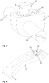
- the figure 1 illustrates an overview of a three-blade folding clasp according to one embodiment.
- the folding clasp comprises a central branch 1 articulated at each of its ends, on one end of a first blade 2 and a second blade 3, each of the blades 2, 3 being foldable around joints 4.
- These blades 2, 3 comprise at their ends not connected to the central branch 1 fastening means (not shown) for holding the blades 2, 3 in the closed position of the clasp folded on the central branch 1.
- These fixing means may be for example any type mechanical clipping means or resilient fixing means for locking the blades 2, 3 in the closed position.
- the clasp 10 comprises a fastening element 7 intended to be fixed in a short strand 8 of the bracelet.
- a detail view of the hooking element 7 is shown in FIG. figure 3 .
- the attachment element 7 comprises a stud 9 provided with an oblong-shaped head 11.
- pin 9 is illustrated as a separate part of the attachment element 7 in which the pin 9 is assembled by means of a peg pin 9 fitting into a groove of the element of hanging 7.
- the figures 4 and 5 are a detailed view of the first blade 2 showing a form against 13.
- the attachment element 7 also comprises a hinge pin 12 transversely passing through the fastening element.
- the end of the short strand 8 can be wound around the hinge axis 12 so as to fix the fastening element 7 on the short strand 8 in an articulated manner.
- the first blade 2 is provided with the counter-form 13 intended to receive the stud 9 with the oblong-shaped head 11.
- the counterform 13 is a blind or through-shaped cavity made in the first blade 2.
- the cavity defining the counter form 13 comprises a first portion 14 and a third portion 22, each of lateral dimension greater than the lateral dimension of the elongated head 11.
- the cavity defining the counter form 13 also comprises a second portion 15 conforming with the shape of the oblong-shaped head 11 of the pin 9.
- the short strand 8 can be mounted on the first blade 2 of the buckle 1 by introducing the stud 9 into the first portion 14 of the counter form 13.
- the short strand 8 (and the fastening element 7) is then pivoted relative to an axis 23 of the counter form 13 (see FIG. figure 2 ), in a first position in which the oblong-shaped head 11 is aligned with the second conforming portion.
- the oblong-shaped head 11 can be pivoted in all pivotal orientations with respect to the axis 23.
- the head 11 can pass through the second portion 15 into the third portion 22.
- the short strand 8 can be pivoted again relative to the axis 23 so as to lock the head 11 in the against form 13. In this latter position, the attachment element 7 is mounted on the first blade 2.
- the first position of the attachment element 7 corresponds to a position of the short strand 8 being rotated about 180 ° relative to the position of the short strand 8 when the bracelet is worn.
- the second position of the fastening element 7 corresponds to a position of the short strand 8 being rotated about 180 ° with respect to the first position.
- the attachment element 7 also comprises latching means, such as a ball pawl 16 cooperating with a recess 17 formed by the first blade 2.
- the latching means are configured so as to immobilize and maintain the hooking element 7 in the second position, when mounted in the first blade 2.
- the free end of the second blade 3 carries a device 18 for adjusting the useful length of the long strand of the bracelet (not shown) intended to be associated with the clasp 10.
- the adjusting device 18 is shown comprising a cover 19 and carrying side walls 20.
- the adjustment device 18 accommodates one end of the long strand of the bracelet in a conventional manner.
- the long strand thus received in the adjusting device 18 can extend, according to the adjustment of its length, in guide loops 21, above the short strand 8.
- the first blade 2 prevents the pivoting of the attachment element 7 and the short strand 8 around the counter form 13.
- the clasp can not open as long as the long strand is mounted on the clasp 10 .
- the hooking element 7 can pivot relative to the counter form 13. As long as the bracelet is worn, the hooking element 7 will not be detached from the first blade 2 , since the hooking element 7 can not pivot to the first position of the short strand 8 and the attachment element 7 where a stall is possible.
- the fastening element 7 is made of titanium or titanium alloy so as to obtain good mechanical strength.
- a fastening element 7 made of titanium or titanium alloy may be used in combination with other elements of the clasp made of a material other than titanium.
- the body of the fastening element 7 may be made of a material other than titanium or titanium alloy, such as an alloy of a precious metal, and a titanium or alloy insert. of titanium comprising counter form 13 may be provided in the fastening element 7.
- clasp 10 of the invention An advantage of the clasp 10 of the invention is that the clasp can be removed from the wristband simply and without tools.
- the clasp 10 is interchangeable, that is to say that it can be used on other bracelets, provided that the fastening element 7 is previously attached to the short strand of the other bracelets.
- a single clasp can therefore be used with several different bracelets that do not need to be dedicated to the clasp 10 but which may be existing bracelets on which the clasp 10 is adapted.
- the clasp 10 of the invention is based on a simple and robust mechanical locking. It does not require a pusher or elastic elements.
- the clasp 10 is also discrete since its components such as the fastening element 7 are invisible to the wearer when the bracelet is worn.
- the pin 9 and the attachment element 7 are formed as a single piece.
- the fastening element 7 of the invention can be used with another clasp system, for example a clasp with two blades or any other type of folding clasp.
- the clasp of the invention can be applied to a clasp of a bracelet associated with a wristwatch.
- the clasp of the invention can be associated with any other bracelet for any object to be fixed on a wrist or any other part. This object can also be a jewelery component.
Landscapes
- Buckles (AREA)
Description
- La présente invention concerne un fermoir à boucle déployante pour bracelet et qui est interchangeable entre divers bracelets.
- On connait de tels fermoirs du type déployant à deux ou trois lames, comme celui décrit dans le document
EP0775455 , ou tout autre type de fermoirs permettant de rapprocher et fixer deux brins d'un bracelet dans une position fermée et de séparer ces deux brins du bracelet dans une position ouverte. - Ces fermoirs connus présentent notamment l'inconvénient de nécessiter l'usage d'outils spéciaux pour la fixation des brins du bracelet aux parties correspondantes du fermoir et surtout de ne pas pouvoir recevoir différents types de bracelets, par exemple souples ou métalliques, c'est-à-dire à maillons rigides articules les uns aux autres. En effet, le mode de fixation de l'extrémité d'un bracelet sur une extrémité du fermoir est diffèrent qu'il s'agisse d'un bracelet souple ou d'un bracelet métallique. Ainsi, un même fermoir ne peut pas être utilisé avec différents types de bracelets.
- Le document
EP1188389 décrit un fermoir comprenant deux pièces de liaison interchangeables pouvant être fixées et articulées sur l'extrémité libre des lames du fermoir à l'aide d'un dispositif de verrouillage. Les pièces de liaison sont conformées de manière à recevoir chacune un brin d'un bracelet souple ou d'un bracelet-chaine. La fixation des pièces de liaison sur l'extrémité des lames du fermoir est réalisée à l'aide d'un axe d'articulation traversant transversalement lesdites pièces de liaison et l'extrémité libre des lames servant d'axe de liaison et d'articulation. Cet axe comporte une gorge annulaire dans laquelle vient se loger un verrou solidaire d'un poussoir soumis à l'action d'un ressort. Pour séparer la pièce de liaison du fermoir lors d'un changement de bracelet par exemple, l'usager doit pousser sur le poussoir à l'aide de la pointe d'un stylo et faire coulisser l'axe. Cependant, chacune des paires de pièces de liaison doit être spécialement conformée pour recevoir un bracelet souple ou un bracelet à maillons rigides articulés les uns aux autres. - Le document
FR2819695 - Le document
DE267495 décrit un système de verrouillage de sécurité pour les bijoux comprenant un système de sécurité et le documentDE19746476 décrit un tel système pour une chaine permettant un trajet de chaîne harmonieuse, même à des positions différentes dans la zone du décolleté. - Le document
US7788774 décrit un fermoir pour relier de manière amovible les extrémités libres des chaînes, des fils ou des câbles, et plus particulièrement un fermoir de verrouillage de torsion pour les bijoux tels que colliers, chaînes de cou, chaîne bracelets et autres. Le documentFR2692116 - La présente invention concerne un fermoir à boucle déployante pour un bracelet destiné à être porté, comprenant une première lame fixée de manière dépliable et repliable autour d'une articulation sur une seconde lame; le fermoir comprenant un élément d'accrochage pourvu un piton et destiné à venir se fixer dans un premier brin du bracelet, et une cavité borgne ou traversante définissant une contre forme, pratiquée dans la première lame et configurée pour coopérer avec ledit piton; la contre forme étant configurée de manière à ce que l'élément d'accrochage puisse pivoter librement dans un plan de la première lame, dans une première position permettant de monter l'élément d'accrochage sur la première lame de manière amovible, et dans une seconde position permettant de monter l'élément d'accrochage sur la première lame (2) de manière fixe.
- La solution proposée permet d'obtenir un fermoir interchangeable qui s'adapte à divers bracelets, quelle que soit la matière du bracelet. La boucle déployante de l'invention peut être aisément enlevée d'un bracelet pour être utilisée avec un autre bracelet, sans l'aide d'outils.
- Des exemples de mise en oeuvre de l'invention sont indiqués dans la description illustrée par les figures annexées dans lesquelles :
- la
figure 1 illustre une vue d'ensemble d'un fermoir déployant comprenant une première et seconde lame montées articulées sur une branche centrale, et un élément d'accrochage destiné à être fixé sur un bracelet, selon un mode de réalisation; - la
figure 2 montre une vue de détail de l'élément d'accrochage monté sur la première lame, selon un mode de réalisation; - la
figure 3 montre une vue de détail de l'élément d'accrochage, selon un mode de réalisation; - les
figures 4 et5 montrent vue de détail de la première lame, selon un mode de réalisation; et - la
figure 6 montre l'élément d'accrochage monté sur la première lame, selon un autre mode de réalisation. - La
figure 1 illustre une vue d'ensemble d'un fermoir déployant 10 à trois lames, selon un mode de réalisation. Le fermoir déployant comprend une branche centrale 1 articulée à chacune de ses extrémités, sur une extrémité d'une première lame 2 et d'une seconde lame 3, chacune des lames 2, 3 étant repliable autour d'articulations 4. Ces lames 2, 3 comportent à leurs extrémités non reliées à la branche centrale 1 des moyens de fixation (non représentés) permettant à maintenir les lames 2, 3 en position fermée du fermoir repliées sur la branche centrale 1. Ces moyens de fixation peuvent être par exemple tout type de moyens de clipsage mécanique ou moyens de fixation élastiques, permettant de verrouiller les lames 2, 3 en position fermée. - Le fermoir 10 comprend un élément d'accrochage 7 destiné à venir se fixer dans un brin court 8 du bracelet. Une vue de détail de l'élément d'accrochage 7 est montrée à la
figure 3 . L'élément d'accrochage 7 comprend un piton 9 pourvu d'une tête en forme d'oblong 11. - Dans l'exemple de la
figure 2 , piton 9 est illustré comme une pièce distincte de l'élément d'accrochage 7 dans lequel le piton 9 vient s'assembler par l'intermédiaire d'une cheville du piton 9 venant s'insérer dans une gorge de l'élément d'accrochage 7. - Les
figures 4 et5 sont une vue de détail de la première lame 2 montrant une contre forme 13. L'élément d'accrochage 7 comprend également un axe d'articulation 12 traversant transversalement l'élément d'accrochage. L'extrémité du brin court 8 peut être enroulée autour de l'axe d'articulation 12 de sorte à fixer l'élément d'accrochage 7 sur le brin court 8 de manière articulée. - La première lame 2 est pourvue de la contre forme 13 destinée à recevoir le piton 9 avec la tête en forme d'oblong 11. La contre forme 13 est une cavité, borgne ou traversante, pratiquée dans la première lame 2. Dans l'exemple illustré, la cavité définissant la contre forme 13 comporte une première portion 14 et une troisième portion 22, chacune de dimension latérale supérieure à la dimension latérale de la tête en forme d'oblong 11. La cavité définissant la contre forme 13 comporte également une seconde portion 15 conforme avec la forme de la tête en forme d'oblong 11 du piton 9.
- Lorsque l'élément d'accrochage 7 est fixé sur le brin court 8 du bracelet, le brin court 8 peut être monté sur la première lame 2 de la boucle 1 en introduisant le piton 9 dans la première portion 14 de la contre forme 13. Le brin court 8 (et l'élément d'accrochage 7) est ensuite pivoté par rapport à un axe 23 de la contre forme 13 (voir
figure 2 ), dans une première position dans laquelle la tête en forme d'oblong 11 est alignée avec la seconde portion 15 conforme. Dans la première portion 14, la tête en forme d'oblong 11 peut être pivotée dans toutes les orientations de pivotement par rapport à l'axe 23. Une fois alignée avec la seconde portion 15, la tête 11 peut passer au travers de la seconde portion 15 jusque dans la troisième portion 22. Lorsque la tête 11 a traversé dans la troisième portion 22, le brin court 8 peut être de nouveau pivoté par rapport à l'axe 23 de manière à bloquer la tête 11 dans la contre forme 13. Dans cette dernière position, l'élément d'accrochage 7 est monté sur la première lame 2. - Selon une forme d'exécution préférée, la première position de l'élément d'accrochage 7 correspond à une position du brin court 8 étant pivotée à environ 180° par rapport à la position du brin court 8 lorsque le bracelet est porté. La seconde position de l'élément d'accrochage 7 correspond à une position du brin court 8 étant pivotée à environ 180° par rapport à la première position.
- Dans un mode de réalisation, l'élément d'accrochage 7 comprend également des moyens d'encliquetage, tel qu'un cliquet à bille 16 coopérant avec une creusure 17 pratiquée la première lame 2. Les moyens d'encliquetage sont configurés de manière à immobiliser et maintenir l'élément d'accrochage 7 dans la seconde position, lorsqu'il est monté dans la première lame 2.
- De retour à la
figure 1 , l'extrémité libre de la seconde lame 3 porte un dispositif de réglage 18 de la longueur utile du brin long du bracelet (non représenté) destiné à être associe au fermoir 10. Dans lafigure 1 , le dispositif de réglage 18 est représenté comprenant un capot 19 et portant des parois latérales 20. Le dispositif de réglage 18 permet de loger une extrémité du brin long du bracelet de manière conventionnelle. Le brin long ainsi reçu dans le dispositif de réglage 18 peut s'étendre, selon le réglage de sa longueur, dans des passants de guidage 21, au-dessus du brin court 8. - Lorsque les lames 2, 3 sont clipsées en position fermée du fermoir 10 repliées sur la branche centrale 1, la proximité de la seconde lame 3, sur lequel est fixée le brin long (non représenté), de la première lame 2 empêche le pivotement de l'élément d'accrochage 7 et du brin court 8 autour de la contre forme 13. D'autre part, le brin long du bracelet s'étendant au-dessus du brin court 8 et de l'élément d'accrochage 7, dans les passants de guidage 21, empêche également le pivotement de l'élément d'accrochage 7 et du brin court 8 autour de la contre forme 13. Le fermoir ne peut donc pas s'ouvrir tant que le brin long est monté sur le fermoir 10.
- Par contre, lorsque la boucle déployante est ouverte, l'élément d'accrochage 7 peut pivoter par rapport à la contre forme 13. Tant que le bracelet est porté, l'élément d'accrochage 7 ne se décrochera pas de la première lame 2, puisque l'élément d'accrochage 7 ne peut pivoter jusqu'à la première position du brin court 8 et de l'élément d'accrochage 7 où un décrochage est possible.
- Encore selon une forme d'exécution, l'élément d'accrochage 7 est fabriqué en titane ou en alliage de titane de sorte à obtenir une bonne résistance mécanique. Un élément d'accrochage 7 en titane ou en alliage de titane peut être utilisé en combinaison avec d'autres éléments du fermoir fabriqué dans un autre matériau que le titane. Par exemple, le corps de l'élément d'accrochage 7 peut être fabriqué dans un matériau autre que le titane ou l'alliage de titane, tel qu'un alliage d'un métal précieux, et d'un insert en titane ou alliage de titane comprenant la contre forme 13 peut être prévu dans l'élément d'accrochage 7.
- Un avantage du fermoir 10 de l'invention est que le fermoir peut être enlevé du bracelet simplement et sans outils. En outre, le fermoir 10 est interchangeable, c'est-à-dire qu'il peut être utilisé sur d'autres bracelets, pourvu que l'élément d'accrochage 7 est préalablement fixé sur le brin court des autres bracelets. Un seul fermoir peut donc être utilisé avec plusieurs bracelets différents qui n'ont pas besoin d'être dédiés pour le fermoir 10 mais qui peuvent être des bracelets existants sur lequel le fermoir 10 vient s'adapter.
- Le fermoir 10 de l'invention est basé sur un verrouillage mécanique simple et robuste. Il ne requiert pas de poussoir ni d'éléments élastiques. Le fermoir 10 est également discret puisque ses composants tels que l'élément d'accrochage 7 sont invisibles au porteur lorsque le bracelet est porté.
- Il va de soi que la présente invention n'est pas limitée au mode de réalisation qui vient d'être décrit et que diverses modifications et variantes simples peuvent être envisagées par l'homme de métier sans sortir du cadre de la présente invention.
- Par exemple, dans la
figure 6 , le piton 9 et l'élément d'accrochage 7 sont formés comme une seule pièce monobloc. - L'élément d'accrochage 7 de l'invention peut être utilisé avec un autre système de fermoir, par exemple un fermoir à deux lames ou tout autre type de fermoir dépliant.
- D'autre part, le fermoir de l'invention peut s'appliquer à un fermoir d'un bracelet associé à une montre-bracelet. En variante, le fermoir de l'invention peut être associé à tout autre bracelet, pour tout objet à fixer sur un poignet ou toute autre partie. Cet objet peut également être un composant de joaillerie.
-
- 1
- branche centrale
- 2
- première lame
- 3
- seconde lame
- 4
- articulations
- 5
- formations
- 6
- formations
- 7
- élément d'accrochage
- 8
- brin court
- 9
- piton
- 10
- fermoir déployant
- 11
- tête en forme d'oblong
- 12
- axe d'articulation
- 13
- contre forme
- 14
- première portion
- 15
- seconde portion
- 16
- cliquet à bille
- 17
- creusure
- 18
- dispositif de réglage
- 19
- capot
- 20
- parois latérales
- 21
- passant de guidage
- 22
- troisième portion
- 23
- axe de la contre forme
Claims (12)
- Fermoir (10) à boucle déployante pour un bracelet, comprenant:une première lame (2) fixée de manière dépliable et repliable autour d'une articulation (4) sur une seconde lame (1);le fermoir comprenant un élément d'accrochage (7) pourvu d'un piton (9) et destiné à venir se fixer dans un premier brin (8) du bracelet; et une cavité borgne ou traversante définissant une contre forme (13), pratiquée dans la première lame (2) et configurée pour coopérer avec ledit piton (9); caractérisé en ce que la contre forme (13) est configurée de manière à ce que l'élément d'accrochage (7) puisse pivoter librement dans un plan de la première lame (2), dans une première position permettant de monter l'élément d'accrochage (7) sur la première lame (2) de manière amovible, et dans une seconde position permettant de monter l'élément d'accrochage (7) sur la première lame (2) de manière fixe.
- Le fermoir selon la revendication 1,
dans lequel la première position de l'élément d'accrochage (7) correspond à une position du brin court (8) étant pivotée à environ 180° par rapport à la position du brin court (8) lorsque le bracelet est porté. - Le fermoir selon la revendication 2,
dans lequel la seconde position de l'élément d'accrochage (7) correspond à une position du brin court (8) étant pivotée à environ 180° par rapport à la première position. - Le fermoir selon l'une des revendications 1 à 3,
dans lequel il comprend des moyens d'encliquetage (16, 17) configurés de manière à immobiliser et maintenir l'élément d'accrochage (7) dans la seconde position, lorsqu'il est monté dans la première lame (2). - Le fermoir selon la revendication 4,
dans lequel les moyens d'encliquetage comprennent un cliquet à bille (16) inclut dans l'élément d'accrochage (7) et coopérant avec une creusure (17) pratiquée dans la première lame (2). - Le fermoir selon l'une des revendications 1 à 5,
dans lequel le piton (9) est pourvu d'une tête en forme d'oblong (11); et dans lequel la cavité définissant la contre forme (13) comprend une première portion (14) et une troisième portion (22) de dimension latérale supérieure à la dimension latérale de la tête en forme d'oblong (11) et une seconde portion (15) conforme avec la forme de la tête en forme d'oblong (11);
la tête (11) étant introduite de manière amovible dans la première portion (14) lorsque l'élément d'accrochage (7) est dans la première position et la tête (11) étant introduite de manière fixe dans la troisième portion (22) lorsque l'élément d'accrochage (7) est dans la seconde position. - Le fermoir selon l'une des revendications 1 à 6,
étant configuré de sorte à empêcher le pivotement de l'élément d'accrochage (7) dans la première position lorsque le bracelet est porté. - Le fermoir selon l'une des revendications 1 à 7,
dans lequel l'élément d'accrochage (7) est fabriqué en titane ou en alliage de titane. - Le fermoir selon la revendication 8,
dans lequel la contre forme (13) est comprise dans un insert inclut dans l'élément d'accrochage (7). - Le fermoir selon l'une des revendications 1 à 9,
étant configuré de sorte que, lorsque la première lame (2) est repliée sur la seconde lame (1) dans une position fermée du fermoir, l'élément d'accrochage (7) ne peut pas pivoter. - Le fermoir selon l'une des revendications 1 à 10,
dans lequel le premier brin (8) est un brin court du bracelet. - Le fermoir selon la revendication 11,
dans lequel, en position fermée du fermoir (10), le second brin du bracelet s'étend au-dessus du brin court (8), empêchant le pivotement de l'élément d'accrochage (7).
Applications Claiming Priority (1)
| Application Number | Priority Date | Filing Date | Title |
|---|---|---|---|
| CH7842015 | 2015-06-02 |
Publications (2)
| Publication Number | Publication Date |
|---|---|
| EP3100630A1 EP3100630A1 (fr) | 2016-12-07 |
| EP3100630B1 true EP3100630B1 (fr) | 2018-05-16 |
Family
ID=56363690
Family Applications (1)
| Application Number | Title | Priority Date | Filing Date |
|---|---|---|---|
| EP16172518.9A Active EP3100630B1 (fr) | 2015-06-02 | 2016-06-01 | Fermoir à boucle déployante interchangeable |
Country Status (1)
| Country | Link |
|---|---|
| EP (1) | EP3100630B1 (fr) |
Family Cites Families (9)
| Publication number | Priority date | Publication date | Assignee | Title |
|---|---|---|---|---|
| DE267495C (de) | 1913-09-07 | 1913-11-20 | Max Schreiber | Sicherheitsschloss für schmucksachen |
| CH250977A (fr) * | 1945-02-22 | 1947-09-30 | Cornu Ami | Fermoir pour bracelet. |
| JPS4422930Y1 (fr) * | 1967-06-19 | 1969-09-27 | ||
| FR2692116B1 (fr) * | 1992-06-10 | 1994-08-19 | Boucledor Sa | Moyens de verrouillage d'un fermoir de bracelet à boucle déployante. |
| FR2741244B1 (fr) | 1995-11-21 | 1998-01-16 | Grandjean Sa | Fermoir a boucle deployante |
| DE19746476C2 (de) | 1997-10-22 | 2002-02-21 | Michael Schleicher | Verschluß für eine Schmuckkette |
| DE60018066T2 (de) | 2000-08-22 | 2006-01-12 | Richemont International S.A. | Armbandverschluss |
| FR2819695A1 (fr) | 2001-01-22 | 2002-07-26 | Celine Pantaleo | Fermoir de securite |
| US7788774B1 (en) | 2007-09-10 | 2010-09-07 | Paul Brian Cravey | Twist lock clasp and coupling method |
-
2016
- 2016-06-01 EP EP16172518.9A patent/EP3100630B1/fr active Active
Non-Patent Citations (1)
| Title |
|---|
| None * |
Also Published As
| Publication number | Publication date |
|---|---|
| EP3100630A1 (fr) | 2016-12-07 |
Similar Documents
| Publication | Publication Date | Title |
|---|---|---|
| EP1790247B1 (fr) | Dispositif de réglage de la longueur d'un bracelet, bracelet muni d'un tel dispositif, et montre équipée d'un tel bracelet | |
| WO2017081071A1 (fr) | Bijou à porter au doigt comportant une liaison glissière | |
| CH704810A1 (fr) | Brin de bracelet flexible. | |
| EP1943917B1 (fr) | Fermoir à boucle déployante pour bracelet | |
| FR2548879A1 (fr) | Charniere demontable pour bracelet | |
| EP3266335A1 (fr) | Montre bracelet | |
| EP1188389B1 (fr) | Fermoir pour bracelet | |
| FR3094873A1 (fr) | mini boucle déployante avec longerons rigides | |
| EP3470935A1 (fr) | Système de clipsage par exemple pour attacher un bracelet a une montre | |
| EP3100630B1 (fr) | Fermoir à boucle déployante interchangeable | |
| EP3329796B1 (fr) | Dispositif de reglage de confort de la longueur d'un bracelet | |
| CH713091A2 (fr) | Système de clipsage pour attacher un bracelet à une montre. | |
| EP1785784A2 (fr) | Dispositif de fixation d'un bracelet de montre | |
| CH650389A5 (fr) | Fermoir de bracelet a boucle deployante. | |
| FR2601864A1 (fr) | Dispositif d'attache pour article de bijouterie, d'horlogerie ou de maroquinerie notamment pour montre | |
| WO2021099332A1 (fr) | Article de bijouterie comprenant un fermoir | |
| FR3093897A1 (fr) | Boucle déployante avec longerons rigides parallèles | |
| EP1240841B1 (fr) | Fermoir déployant pour bracelet de montre interchangeable | |
| EP4129110A1 (fr) | Article de bijouterie ou de maroquinerie | |
| CH701804A2 (fr) | Fermoir de bracelet avec dispositif de mise en longueur. | |
| WO2018002789A1 (fr) | Boucle pour ceinture, pièce de bijouterie ou d'horlogerie | |
| CH702693B1 (fr) | Bracelet de montre. | |
| EP3379344B1 (fr) | Bracelet souple a largeur adaptable | |
| FR2743641A1 (fr) | Montre-bracelet a cornes munie d'un dispositif de fixation d'un bracelet aux cornes et bracelet pour une telle montre | |
| CH710931B1 (fr) | Dispositif comportant une sangle et un module à fonction électronique intégré dans un fermoir. |
Legal Events
| Date | Code | Title | Description |
|---|---|---|---|
| PUAI | Public reference made under article 153(3) epc to a published international application that has entered the european phase |
Free format text: ORIGINAL CODE: 0009012 |
|
| AK | Designated contracting states |
Kind code of ref document: A1 Designated state(s): AL AT BE BG CH CY CZ DE DK EE ES FI FR GB GR HR HU IE IS IT LI LT LU LV MC MK MT NL NO PL PT RO RS SE SI SK SM TR |
|
| AX | Request for extension of the european patent |
Extension state: BA ME |
|
| 17P | Request for examination filed |
Effective date: 20170517 |
|
| RBV | Designated contracting states (corrected) |
Designated state(s): AL AT BE BG CH CY CZ DE DK EE ES FI FR GB GR HR HU IE IS IT LI LT LU LV MC MK MT NL NO PL PT RO RS SE SI SK SM TR |
|
| RIC1 | Information provided on ipc code assigned before grant |
Ipc: A44C 5/24 20060101AFI20170928BHEP |
|
| GRAP | Despatch of communication of intention to grant a patent |
Free format text: ORIGINAL CODE: EPIDOSNIGR1 |
|
| INTG | Intention to grant announced |
Effective date: 20171206 |
|
| GRAS | Grant fee paid |
Free format text: ORIGINAL CODE: EPIDOSNIGR3 |
|
| GRAA | (expected) grant |
Free format text: ORIGINAL CODE: 0009210 |
|
| AK | Designated contracting states |
Kind code of ref document: B1 Designated state(s): AL AT BE BG CH CY CZ DE DK EE ES FI FR GB GR HR HU IE IS IT LI LT LU LV MC MK MT NL NO PL PT RO RS SE SI SK SM TR |
|
| REG | Reference to a national code |
Ref country code: GB Ref legal event code: FG4D Free format text: NOT ENGLISH |
|
| REG | Reference to a national code |
Ref country code: CH Ref legal event code: EP Ref country code: CH Ref legal event code: NV Representative=s name: P&TS SA, CH |
|
| REG | Reference to a national code |
Ref country code: IE Ref legal event code: FG4D Free format text: LANGUAGE OF EP DOCUMENT: FRENCH |
|
| REG | Reference to a national code |
Ref country code: DE Ref legal event code: R096 Ref document number: 602016003065 Country of ref document: DE |
|
| REG | Reference to a national code |
Ref country code: AT Ref legal event code: REF Ref document number: 998743 Country of ref document: AT Kind code of ref document: T Effective date: 20180615 |
|
| REG | Reference to a national code |
Ref country code: FR Ref legal event code: PLFP Year of fee payment: 3 |
|
| REG | Reference to a national code |
Ref country code: NL Ref legal event code: MP Effective date: 20180516 |
|
| REG | Reference to a national code |
Ref country code: LT Ref legal event code: MG4D |
|
| PG25 | Lapsed in a contracting state [announced via postgrant information from national office to epo] |
Ref country code: LT Free format text: LAPSE BECAUSE OF FAILURE TO SUBMIT A TRANSLATION OF THE DESCRIPTION OR TO PAY THE FEE WITHIN THE PRESCRIBED TIME-LIMIT Effective date: 20180516 Ref country code: SE Free format text: LAPSE BECAUSE OF FAILURE TO SUBMIT A TRANSLATION OF THE DESCRIPTION OR TO PAY THE FEE WITHIN THE PRESCRIBED TIME-LIMIT Effective date: 20180516 Ref country code: BG Free format text: LAPSE BECAUSE OF FAILURE TO SUBMIT A TRANSLATION OF THE DESCRIPTION OR TO PAY THE FEE WITHIN THE PRESCRIBED TIME-LIMIT Effective date: 20180816 Ref country code: NO Free format text: LAPSE BECAUSE OF FAILURE TO SUBMIT A TRANSLATION OF THE DESCRIPTION OR TO PAY THE FEE WITHIN THE PRESCRIBED TIME-LIMIT Effective date: 20180816 Ref country code: FI Free format text: LAPSE BECAUSE OF FAILURE TO SUBMIT A TRANSLATION OF THE DESCRIPTION OR TO PAY THE FEE WITHIN THE PRESCRIBED TIME-LIMIT Effective date: 20180516 Ref country code: ES Free format text: LAPSE BECAUSE OF FAILURE TO SUBMIT A TRANSLATION OF THE DESCRIPTION OR TO PAY THE FEE WITHIN THE PRESCRIBED TIME-LIMIT Effective date: 20180516 |
|
| PG25 | Lapsed in a contracting state [announced via postgrant information from national office to epo] |
Ref country code: NL Free format text: LAPSE BECAUSE OF FAILURE TO SUBMIT A TRANSLATION OF THE DESCRIPTION OR TO PAY THE FEE WITHIN THE PRESCRIBED TIME-LIMIT Effective date: 20180516 Ref country code: HR Free format text: LAPSE BECAUSE OF FAILURE TO SUBMIT A TRANSLATION OF THE DESCRIPTION OR TO PAY THE FEE WITHIN THE PRESCRIBED TIME-LIMIT Effective date: 20180516 Ref country code: GR Free format text: LAPSE BECAUSE OF FAILURE TO SUBMIT A TRANSLATION OF THE DESCRIPTION OR TO PAY THE FEE WITHIN THE PRESCRIBED TIME-LIMIT Effective date: 20180817 Ref country code: LV Free format text: LAPSE BECAUSE OF FAILURE TO SUBMIT A TRANSLATION OF THE DESCRIPTION OR TO PAY THE FEE WITHIN THE PRESCRIBED TIME-LIMIT Effective date: 20180516 Ref country code: RS Free format text: LAPSE BECAUSE OF FAILURE TO SUBMIT A TRANSLATION OF THE DESCRIPTION OR TO PAY THE FEE WITHIN THE PRESCRIBED TIME-LIMIT Effective date: 20180516 |
|
| REG | Reference to a national code |
Ref country code: AT Ref legal event code: MK05 Ref document number: 998743 Country of ref document: AT Kind code of ref document: T Effective date: 20180516 |
|
| PG25 | Lapsed in a contracting state [announced via postgrant information from national office to epo] |
Ref country code: AT Free format text: LAPSE BECAUSE OF FAILURE TO SUBMIT A TRANSLATION OF THE DESCRIPTION OR TO PAY THE FEE WITHIN THE PRESCRIBED TIME-LIMIT Effective date: 20180516 Ref country code: DK Free format text: LAPSE BECAUSE OF FAILURE TO SUBMIT A TRANSLATION OF THE DESCRIPTION OR TO PAY THE FEE WITHIN THE PRESCRIBED TIME-LIMIT Effective date: 20180516 Ref country code: EE Free format text: LAPSE BECAUSE OF FAILURE TO SUBMIT A TRANSLATION OF THE DESCRIPTION OR TO PAY THE FEE WITHIN THE PRESCRIBED TIME-LIMIT Effective date: 20180516 Ref country code: SK Free format text: LAPSE BECAUSE OF FAILURE TO SUBMIT A TRANSLATION OF THE DESCRIPTION OR TO PAY THE FEE WITHIN THE PRESCRIBED TIME-LIMIT Effective date: 20180516 Ref country code: RO Free format text: LAPSE BECAUSE OF FAILURE TO SUBMIT A TRANSLATION OF THE DESCRIPTION OR TO PAY THE FEE WITHIN THE PRESCRIBED TIME-LIMIT Effective date: 20180516 Ref country code: CZ Free format text: LAPSE BECAUSE OF FAILURE TO SUBMIT A TRANSLATION OF THE DESCRIPTION OR TO PAY THE FEE WITHIN THE PRESCRIBED TIME-LIMIT Effective date: 20180516 Ref country code: PL Free format text: LAPSE BECAUSE OF FAILURE TO SUBMIT A TRANSLATION OF THE DESCRIPTION OR TO PAY THE FEE WITHIN THE PRESCRIBED TIME-LIMIT Effective date: 20180516 |
|
| REG | Reference to a national code |
Ref country code: DE Ref legal event code: R097 Ref document number: 602016003065 Country of ref document: DE |
|
| PG25 | Lapsed in a contracting state [announced via postgrant information from national office to epo] |
Ref country code: SM Free format text: LAPSE BECAUSE OF FAILURE TO SUBMIT A TRANSLATION OF THE DESCRIPTION OR TO PAY THE FEE WITHIN THE PRESCRIBED TIME-LIMIT Effective date: 20180516 Ref country code: IT Free format text: LAPSE BECAUSE OF FAILURE TO SUBMIT A TRANSLATION OF THE DESCRIPTION OR TO PAY THE FEE WITHIN THE PRESCRIBED TIME-LIMIT Effective date: 20180516 |
|
| REG | Reference to a national code |
Ref country code: BE Ref legal event code: MM Effective date: 20180630 |
|
| REG | Reference to a national code |
Ref country code: IE Ref legal event code: MM4A |
|
| PLBE | No opposition filed within time limit |
Free format text: ORIGINAL CODE: 0009261 |
|
| STAA | Information on the status of an ep patent application or granted ep patent |
Free format text: STATUS: NO OPPOSITION FILED WITHIN TIME LIMIT |
|
| PG25 | Lapsed in a contracting state [announced via postgrant information from national office to epo] |
Ref country code: LU Free format text: LAPSE BECAUSE OF NON-PAYMENT OF DUE FEES Effective date: 20180601 Ref country code: MC Free format text: LAPSE BECAUSE OF FAILURE TO SUBMIT A TRANSLATION OF THE DESCRIPTION OR TO PAY THE FEE WITHIN THE PRESCRIBED TIME-LIMIT Effective date: 20180516 |
|
| 26N | No opposition filed |
Effective date: 20190219 |
|
| PG25 | Lapsed in a contracting state [announced via postgrant information from national office to epo] |
Ref country code: IE Free format text: LAPSE BECAUSE OF NON-PAYMENT OF DUE FEES Effective date: 20180601 |
|
| PG25 | Lapsed in a contracting state [announced via postgrant information from national office to epo] |
Ref country code: SI Free format text: LAPSE BECAUSE OF FAILURE TO SUBMIT A TRANSLATION OF THE DESCRIPTION OR TO PAY THE FEE WITHIN THE PRESCRIBED TIME-LIMIT Effective date: 20180516 Ref country code: BE Free format text: LAPSE BECAUSE OF NON-PAYMENT OF DUE FEES Effective date: 20180630 |
|
| PG25 | Lapsed in a contracting state [announced via postgrant information from national office to epo] |
Ref country code: AL Free format text: LAPSE BECAUSE OF FAILURE TO SUBMIT A TRANSLATION OF THE DESCRIPTION OR TO PAY THE FEE WITHIN THE PRESCRIBED TIME-LIMIT Effective date: 20180516 |
|
| PG25 | Lapsed in a contracting state [announced via postgrant information from national office to epo] |
Ref country code: MT Free format text: LAPSE BECAUSE OF FAILURE TO SUBMIT A TRANSLATION OF THE DESCRIPTION OR TO PAY THE FEE WITHIN THE PRESCRIBED TIME-LIMIT Effective date: 20180516 |
|
| PG25 | Lapsed in a contracting state [announced via postgrant information from national office to epo] |
Ref country code: TR Free format text: LAPSE BECAUSE OF FAILURE TO SUBMIT A TRANSLATION OF THE DESCRIPTION OR TO PAY THE FEE WITHIN THE PRESCRIBED TIME-LIMIT Effective date: 20180516 |
|
| PG25 | Lapsed in a contracting state [announced via postgrant information from national office to epo] |
Ref country code: PT Free format text: LAPSE BECAUSE OF FAILURE TO SUBMIT A TRANSLATION OF THE DESCRIPTION OR TO PAY THE FEE WITHIN THE PRESCRIBED TIME-LIMIT Effective date: 20180516 |
|
| PG25 | Lapsed in a contracting state [announced via postgrant information from national office to epo] |
Ref country code: MK Free format text: LAPSE BECAUSE OF NON-PAYMENT OF DUE FEES Effective date: 20180516 Ref country code: CY Free format text: LAPSE BECAUSE OF FAILURE TO SUBMIT A TRANSLATION OF THE DESCRIPTION OR TO PAY THE FEE WITHIN THE PRESCRIBED TIME-LIMIT Effective date: 20180516 Ref country code: HU Free format text: LAPSE BECAUSE OF FAILURE TO SUBMIT A TRANSLATION OF THE DESCRIPTION OR TO PAY THE FEE WITHIN THE PRESCRIBED TIME-LIMIT; INVALID AB INITIO Effective date: 20160601 |
|
| PG25 | Lapsed in a contracting state [announced via postgrant information from national office to epo] |
Ref country code: IS Free format text: LAPSE BECAUSE OF FAILURE TO SUBMIT A TRANSLATION OF THE DESCRIPTION OR TO PAY THE FEE WITHIN THE PRESCRIBED TIME-LIMIT Effective date: 20180916 |
|
| PGFP | Annual fee paid to national office [announced via postgrant information from national office to epo] |
Ref country code: FR Payment date: 20230628 Year of fee payment: 8 Ref country code: DE Payment date: 20230620 Year of fee payment: 8 |
|
| PGFP | Annual fee paid to national office [announced via postgrant information from national office to epo] |
Ref country code: GB Payment date: 20230622 Year of fee payment: 8 Ref country code: CH Payment date: 20230702 Year of fee payment: 8 |