EP3100570B1 - Funkknoten, kommunikationsvorrichtungen und verfahren darin - Google Patents
Funkknoten, kommunikationsvorrichtungen und verfahren darin Download PDFInfo
- Publication number
- EP3100570B1 EP3100570B1 EP14881120.1A EP14881120A EP3100570B1 EP 3100570 B1 EP3100570 B1 EP 3100570B1 EP 14881120 A EP14881120 A EP 14881120A EP 3100570 B1 EP3100570 B1 EP 3100570B1
- Authority
- EP
- European Patent Office
- Prior art keywords
- pattern
- communication device
- radio
- radio resource
- carrier band
- Prior art date
- Legal status (The legal status is an assumption and is not a legal conclusion. Google has not performed a legal analysis and makes no representation as to the accuracy of the status listed.)
- Not-in-force
Links
- 238000004891 communication Methods 0.000 title claims description 304
- 238000000034 method Methods 0.000 title claims description 38
- 238000012545 processing Methods 0.000 claims description 31
- 230000011664 signaling Effects 0.000 claims description 14
- 238000001228 spectrum Methods 0.000 description 12
- 230000005540 biological transmission Effects 0.000 description 10
- 238000004590 computer program Methods 0.000 description 8
- 230000006870 function Effects 0.000 description 8
- 230000001413 cellular effect Effects 0.000 description 6
- 238000010586 diagram Methods 0.000 description 6
- 238000005516 engineering process Methods 0.000 description 5
- 238000001514 detection method Methods 0.000 description 4
- 238000005259 measurement Methods 0.000 description 3
- 238000010295 mobile communication Methods 0.000 description 3
- 238000013461 design Methods 0.000 description 2
- 230000007774 longterm Effects 0.000 description 2
- 241000760358 Enodes Species 0.000 description 1
- 238000013459 approach Methods 0.000 description 1
- 230000009286 beneficial effect Effects 0.000 description 1
- 239000000969 carrier Substances 0.000 description 1
- 230000000694 effects Effects 0.000 description 1
- 238000012423 maintenance Methods 0.000 description 1
- 239000000203 mixture Substances 0.000 description 1
- 238000013468 resource allocation Methods 0.000 description 1
- 230000003595 spectral effect Effects 0.000 description 1
Images


Classifications
-
- H—ELECTRICITY
- H04—ELECTRIC COMMUNICATION TECHNIQUE
- H04W—WIRELESS COMMUNICATION NETWORKS
- H04W72/00—Local resource management
- H04W72/04—Wireless resource allocation
- H04W72/044—Wireless resource allocation based on the type of the allocated resource
- H04W72/0453—Resources in frequency domain, e.g. a carrier in FDMA
-
- H—ELECTRICITY
- H04—ELECTRIC COMMUNICATION TECHNIQUE
- H04B—TRANSMISSION
- H04B1/00—Details of transmission systems, not covered by a single one of groups H04B3/00 - H04B13/00; Details of transmission systems not characterised by the medium used for transmission
- H04B1/69—Spread spectrum techniques
- H04B1/713—Spread spectrum techniques using frequency hopping
-
- H—ELECTRICITY
- H04—ELECTRIC COMMUNICATION TECHNIQUE
- H04W—WIRELESS COMMUNICATION NETWORKS
- H04W72/00—Local resource management
- H04W72/50—Allocation or scheduling criteria for wireless resources
- H04W72/54—Allocation or scheduling criteria for wireless resources based on quality criteria
- H04W72/541—Allocation or scheduling criteria for wireless resources based on quality criteria using the level of interference
-
- H—ELECTRICITY
- H04—ELECTRIC COMMUNICATION TECHNIQUE
- H04W—WIRELESS COMMUNICATION NETWORKS
- H04W76/00—Connection management
- H04W76/10—Connection setup
- H04W76/14—Direct-mode setup
Definitions
- Embodiments herein relate to a radio node, communication devices and methods therein in a radio communications network.
- embodiments herein relate to enable communication over a device-to-device connection.
- wireless terminals also known as mobile stations and/or user equipments (UEs) communicate via a Radio Access Network (RAN) to one or more core networks.
- the radio access network covers a geographical area which is divided into cell areas, with each cell area being served by a base station, e.g., a radio base station (RBS), which in some networks may also be called, for example, a "NodeB” or "eNodeB".
- RBS radio base station
- a cell is a geographical area where radio coverage is provided by the radio base station at a base station site or an antenna site in case the antenna and the radio base station are not collocated. Each cell is identified by an identity within the local radio area, which is broadcast in the cell.
- One base station may have one or more cells.
- a cell may be downlink (DL) and/or uplink (UL) cell.
- DL means communication from the base station to the UE and UL means communication from the UE to the base station.
- the base stations communicate over the air interface operating on radio frequencies with the user equipments within range of the base stations.
- a Universal Mobile Telecommunications System is a third generation mobile communication system, which evolved from the second generation (2G) Global System for Mobile Communications (GSM).
- the UMTS terrestrial radio access network is essentially a RAN using wideband code division multiple access (WCDMA) and/or High Speed Packet Access (HSPA) for user equipments.
- WCDMA wideband code division multiple access
- HSPA High Speed Packet Access
- 3GPP Third Generation Partnership Project
- telecommunications suppliers propose and agree upon standards for third generation networks and UTRAN specifically, and investigate enhanced data rate and radio capacity.
- the RAN as e.g.
- RNC radio network controller
- BSC base station controller
- the Evolved Packet System comprises the Evolved Universal Terrestrial Radio Access Network (E-UTRAN), also known as the Long Term Evolution (LTE) radio access, and the Evolved Packet Core (EPC), also known as System Architecture Evolution (SAE) core network.
- E-UTRAN/LTE is a variant of a 3GPP radio access technology wherein the radio base station nodes are directly connected to the EPC core network rather than to RNCs.
- the functions of a RNC are distributed between the radio base stations nodes, e.g. eNodeBs in LTE, and the core network.
- the Radio Access Network (RAN) of an EPS has an essentially "flat" architecture comprising radio base station nodes without reporting to RNCs.
- D2D communication is widely used as a component of many existing wireless technologies, including ad hoc and cellular networks. Examples include Bluetooth and several variants of the IEEE 802.11 standards suite such as WiFi Direct. These systems operate in unlicensed spectrums of radio resources.
- D2D communications as an underlay to cellular networks have been proposed as a means to take advantage of the proximity of communicating communication devices and at the same time to allow communication devices to operate in a controlled interference environment.
- D2D communication shares the same spectrum of radio resources as the cellular network, for example by reserving some of the cellular uplink radio resources for D2D purposes.
- Allocating dedicated spectrum of radio resources for D2D purposes is a less likely alternative as spectrum of radio resources is a scarce radio resource and, dynamic, sharing between the D2D services and cellular services is more flexible and provides higher spectrum efficiency.
- Radio resources for such channels/signals may be assigned by a third controlling node such as an eNB or a control communication device, or the radio resources could be selected autonomously by the transmitting communication device, possibly within a restricted pool of available radio resources.
- TDM Time Division Multiplexing
- FDM Frequency Division Multiplexing
- CDM Code Division Multiplexing
- Radio resources for transmission of data, and control channels, including discovery may be assigned by a controlling node or be defined according to pre-configured patterns.
- each channel from each communication device occupies a subset of the time/frequency and possibly code radio resources in the system.
- Channels with different purpose or associated to, e.g., different service types may be associated to different bandwidths and/or number of Physical Radio resource Blocks (PRB).
- PRB Physical Radio resource Blocks
- SC-OFDM Single Carrier Orthogonal Frequency Division Multiplexing
- frequency and/or time diversity is beneficial in the radio resource patterns used for each physical channel.
- the channels should span different portions of the spectrum in a pseudo-random fashion, a so called frequency hopping. Possibly, code patterns may be exploited, too.
- feedback-based acknowledgement mechanism may not be available, e.g., control channels, broadcast communication channels, discovery channels, etc.
- a possible approach is to provide blind retransmissions, i.e., transmit the same payload multiple times on different radio resources, possibly with different encoding parameters, e.g. redundancy versions.
- the receiver might be able to reconstruct the correct information based on reception of at least some of the retransmissions of the same packet. In order to maximize the detection probability, it is useful to provide frequency hopping between packet retransmissions.
- Frequency Hopping is known since LTE Rel-8, where hopping patterns that sample the frequency spectrum in a pseudo-random fashion are defined and assigned to transmitting communication devices.
- radio resource patterns with frequency hopping and possibly channels with different bandwidth requirements results in an inefficient use of the spectrum of radio resources.
- An object of embodiments herein is to provide a mechanism that enables communication in a radio communications network in an efficient manner.
- the object is achieved by a method in a radio node for enabling communication between a first communication device and a second communication device over a device-to-device, D2D, connection in a radio communications network.
- the radio node allocates radio resource bands of a carrier band for the D2D connection according to at least a first pattern for frequency hopping.
- the radio resource bands are used for frequency hopping over the carrier band and are at a respective carrier band edge and/or at the respective carrier band edge plus or minus a margin such that a contiguous bandwidth of radio resources between the radio resource bands is not used by the first pattern.
- the radio node signals an indication of the allocated radio resource bands to the first communication device and/or the second communication device.
- the object is achieved by a method in a first communication device for enabling communication between the first communication device and a second communication device over a D2D connection in a radio communications network.
- the first communication device obtains an indication of radio resource bands of a carrier band according to at least a first pattern for frequency hopping for the D2D connection.
- the radio resource bands are at a respective carrier band edge and/or at the respective carrier band edge plus or minus a margin such that a contiguous bandwidth of radio resources between the radio resource bands is not used by the first pattern.
- the first communication device uses the indication when setting up the D2D connection to the second communication device.
- the object is achieved by a method in a second communication device for enabling communication between a first communication device and the second communication device over a D2D connection in a radio communications network.
- the second communication device obtains an indication of radio resource bands of a carrier band according to at least a first pattern for frequency hopping for the D2D connection.
- the radio resource bands are at a respective carrier band edge and/or at the respective carrier band edge plus or minus a margin such that a contiguous bandwidth of radio resources between the radio resource bands is not used by the first pattern.
- the second communication device receives, from the first communication device and/or the radio node, an indication of radio resource bands of a pattern used in the D2D connection, and the second communication device uses the pattern indicated by the received indication for communicating with the first communication device.
- a radio node for enabling communication between a first communication device and a second communication device over a D2D connection in a radio communications network.
- the radio node comprises processing means configured to allocate radio resource bands of a carrier band for the D2D connection according to at least a first pattern for frequency hopping.
- the radio resource bands are used for frequency hopping over the carrier band and are at a respective carrier band edge and/or at the respective carrier band edge plus or minus a margin such that a contiguous bandwidth of radio resources between the radio resource bands is not used by the first pattern.
- the processing means is configured to signal an indication of the allocated radio resource bands to the first communication device and/or the second communication device.
- a first communication device for enabling communication between the first communication device and a second communication device over D2D connection in a radio communications network.
- the first communication device comprises processing means configured to obtain an indication of radio resource bands of a carrier band according to at least a first pattern for frequency hopping for the D2D connection.
- the radio resource bands are at a respective carrier band edge and/or at the respective carrier band edge plus or minus a margin such that a contiguous bandwidth of radio resources between the radio resource bands is not used by the first pattern.
- the processing means is configured to use the indication when setting up the D2D connection to the second communication device.
- a second communication device for enabling communication between a first communication device and the second communication device over a D2D connection in a radio communications network.
- the second communication device comprises processing means configured to obtain an indication of radio resource bands of a carrier band according to at least a first pattern for frequency hopping for the D2D connection.
- the radio resource bands are at a respective carrier band edge and/or at the respective carrier band edge plus or minus a margin such that a contiguous bandwidth of radio resources between the radio resource bands is not used by the first pattern.
- the processing means are further configured to receive from the first communication device and/or a radio node, an indication of radio resources of a pattern used in the D2D connection.
- the processing means is further configured to use the pattern indicated by the received indication for communicating with the first communication device.
- Embodiments herein disclose a solution that uses radio resources in an efficient manner as a contiguous bandwidth between the radio resource bands is obtained that may be used for other communication.
- FIG. 1 is a schematic overview depicting a radio communications network 1.
- the radio communications network 1 comprises one or more Radio Access Networks (RAN) and one or more Core Networks (CN).
- the radio communications network 1 may use a number of different technologies, such as Long Term Evolution (LTE), LTE-Advanced, Wideband Code Division Multiple Access (WCDMA), Global System for Mobile communications/Enhanced Data rate for GSM Evolution (GSM/EDGE), Worldwide Interoperability for Microwave Access (WiMax), or Ultra Mobile Broadband (UMB), just to mention a few possible implementations.
- LTE Long Term Evolution
- WCDMA Wideband Code Division Multiple Access
- GSM/EDGE Global System for Mobile communications/Enhanced Data rate for GSM Evolution
- WiMax Worldwide Interoperability for Microwave Access
- UMB Ultra Mobile Broadband
- the radio communications network 1 is exemplified herein as an LTE network.
- a first communication device 10 also known as a mobile station, a user equipment, communication device, and/or a wireless terminal, may communicate via a RAN to one or more CNs.
- first communication device is a non-limiting term which means any wireless terminal, user equipment, Machine Type Communication (MTC) communication device, a device to device (D2D) terminal, or node e.g. Personal Digital Assistant (PDA), laptop, mobile, sensor, relay, mobile tablets or even a small base station communicating within a cell.
- MTC Machine Type Communication
- D2D device to device
- PDA Personal Digital Assistant
- a second communication device 11 is configured to communicate with the first communication device 10 directly, without communicating with a radio node, over a device-to-device (D2D) connection.
- the first communication device 10 is configured to communicate with the second communication device 11 directly, without communicating with a radio node, over a D2D connection.
- the second communication device 11 may also be known as a mobile station, a user equipment, communication device, and/or a wireless terminal, may communicate via a RAN to one or more CNs.
- second communication device is a non-limiting term which means any wireless terminal, user equipment, Machine Type Communication (MTC) communication device, a D2D terminal, or node e.g. Personal Digital Assistant (PDA), laptop, mobile, sensor, relay, mobile tablets or even a small base station communicating within a cell.
- MTC Machine Type Communication
- D2D terminal or node e.g. Personal Digital Assistant (PDA), laptop, mobile, sensor, relay, mobile tablets or even a small base station communicating within a cell.
- PDA Personal Digital Assistant
- the radio communications network 1 covers a geographical area which is divided into cell areas, e.g. a cell 13 being served by a radio node 12.
- the radio node 12 may also be referred to as a base station and e.g. a NodeB, an evolved Node B (eNB, eNode B), a base transceiver station, a radio network controller, Access Point Base Station, base station router, or any other network unit capable of communicating with a user equipment within the cell served by the radio base station depending e.g. on the radio access technology and terminology used.
- the radio node 12 may serve one or more cells, such as the cell 13.
- a cell is a geographical area where radio coverage is provided by radio base station equipment at a base station site and/or at remote locations in Remote Radio Units (RRU).
- the cell definition may also incorporate frequency bands and radio access technology used for transmissions, which means that two different cells may cover the same geographical area but using different frequency bands.
- Each cell is identified by an identity within the local radio area, which is broadcast in the cell. Another identity identifying the cell 13 uniquely in the whole radio communications network 1 is also broadcasted in the cell 13.
- the radio node 12 communicates over the air or radio interface operating on radio frequencies with the user equipment 10 within range of the radio node 12.
- the first/second communication device 10/11 transmits data over the radio interface to the radio node 12 in Uplink (UL) transmissions and the radio node 12 transmits data over an air or radio interface to the communication devices in Downlink (DL) transmissions.
- UL Uplink
- DL Downlink
- Frequency Hopping where hopping patterns that sample the frequency spectrum in a pseudo-random fashion are defined and assigned to transmitting communication devices.
- At least one or more of the following problems may occur if a pattern for frequency hopping similar to legacy LTE UL is used:
- Embodiments herein use ordered patterns of radio resource bands with frequency hopping.
- a first pattern only occupies most external radio resource bands of a carrier band, in an alternating fashion, and successive or following patterns occupy radio resource bands that are either progressively closer to a carrier center of the carrier band, or occupy a same frequency subband, but a different time instance than the radio resource bands of the first pattern.
- one or more patterns out of multiple patterns may be allocated to a D2D connection.
- a contiguous bandwidth for e.g. a UL connection for a third communication device 14 to the radio node 12 is not used by the first pattern or any of the multiple patterns.
- Each pattern may be "narrowband", e.g., associated to the bandwidth of the smallest D2D channel.
- Such multiple patterns are known, specified or configured, also called obtained herein, for all nodes participating to D2D communication.
- Multiple patterns may be arranged in an ordered indexed list, wherein each index indicates a pattern of frequency hopping. For example index '1' indicates pattern 1, index '2' indicates pattern 2 etc.
- D2D communication and UL communication may share the same UL radio resource.
- the radio resource of D2D is assigned by control node or pre-configured. To explore frequency hopping in D2D, it is better to allocate e.g. two separate subbands to D2D at the carrier band edge which would reduce radio resource fractioning of e.g. a data channel allocated between the subbands.
- Embodiments herein fully exploit FH gains without incurring in e.g. frequency radio resources fractioning and cumbersome signalling and utilization of free radio resources.
- the method actions in the radio node 12 for enabling communication between the first communication device 10 and the second communication device 11 over a D2D connection in the radio communications network 1 will now be described with reference to a flowchart depicted in Fig. 2 .
- the actions do not have to be taken in the order stated below, but may be taken in any suitable order. Actions performed in some embodiments are marked with dashed boxes.
- the radio node 12 may be configured with an indexed list of patterns indicating radio resource bands of respective pattern of multiple patterns.
- the radio node 12 may receive an index of a pattern from the first communication device 10.
- the index may indicate an interference-free pattern or a pattern, used or not used by the first communication device 10.
- the radio node 12 allocates radio resource bands of a carrier band for the D2D connection according to at least a first pattern, e.g. pattern 1 or pattern 3 illustrated in Figs. 7-12 , for frequency hopping.
- the radio resource bands are used for frequency hopping over the carrier band and are at a respective carrier band edge and/or at the respective carrier band edge plus or minus a margin such that a contiguous bandwidth of radio resources between the radio resource bands is not used by the first pattern.
- the first pattern of multiple patterns employs radio resources with index x, where x : k x ; N ⁇ 1 ⁇ t x , wherein N defines a number of radio resource blocks of the carrier band and function k x defines the margin to a first radio resource block of the first pattern from a first carrier band edge and N-1-t x defines another radio resource block wherein t x defines the margin to a second carrier band edge, and x is the index indicating the first pattern.
- k x and t x may be based on index of the first pattern.
- the margin may be based on radio resource band of a control channel such as the PUCCH.
- 'x' may take the pattern value of the respective pattern number, e.g. 1,2,3 or 4.
- the indices may be in a list of indices wherein each index indicates a pattern for frequency hopping.
- the radio resource bands of a successive or following pattern for example pattern 2, to the first pattern occupy radio resource bands that occupy a same frequency subband, but at a different time instance than the radio resource bands of the first pattern.
- the radio resource bands of a successive or following pattern e.g. Pattern 3 or 4
- to the first pattern occupy radio resource bands that are progressively closer to a center carrier of the carrier band than the radio resource bands of the first pattern.
- an uplink communication by the third communication device 14 to a radio node uses radio resources of the carrier band.
- At least a fraction of the contiguous bandwidth is for an uplink channel, such as shared uplink channel.
- a bandwidth for a Physical Uplink Shared Channel (PUSCH) is continuous and not fractioned according to embodiments herein.
- the radio node allocates one or more patterns that are contiguous in frequency domain with the first pattern and the one or more patterns are combined with the first pattern to obtain a joint pattern of a desired bandwidth.
- the radio node 12 may take the received indication of interference free pattern into account when allocating the first pattern, e.g. when pattern 2 is reported as an interference free pattern the radio node 12 may allocate pattern 2 for the D2D connection.
- the radio node 12 signals an indication of the allocated radio resource bands, such as an index of the first pattern, to the first communication device 10 and/or the second communication device 11.
- the radio node may signal, to the first communication device 10 and/or the second communication device 11, an index, being the indication, of the first pattern in the joint pattern with a lowest index when assigning radio resource bands.
- Figure 3 is a combined schematic flowchart and signalling scheme according to embodiments herein for setting up a D2D connection between the first communication device 10 and the second communication device 11.
- the first communication device 10 determines a pattern for frequency hopping that is interference free, or has an interference below a certain threshold defining an interference free pattern.
- the first communication device 10 may then send an indication, such as an index or similar, indicating the determined pattern to the radio node 12.
- the radio node 12 allocates, selects or chooses, radio resource bands of a first pattern for frequency hopping to the first communication device 10 for the D2D connection to the second communication device 11.
- the first pattern may be e.g. the pattern corresponding to the index received. This corresponds to the action 202 in Fig. 2 .
- the radio node 12 may allocate a plurality of patterns depending on amount of data traffic needed or indicated as needed.
- the radio node 12 may then transmit an index of the allocated pattern to the first communication device 10. This corresponds to action 203 in Fig. 2 .
- the radio node 12 may additionally or alternatively transmit the index of the pattern to the second communication device 11. This corresponds to action 203 in Fig. 2 . It should be noted that the radio node 12 does not necessarily need to inform the second communication device 11 of the allocated pattern, instead it may be the first communication device 10 that informs the second communication device 11 of the received index.
- the first communication device 10 and the second communication device 11 then uses the pattern indicated by the received index and sets up the D2D connection.
- the method actions in the first communication device 10 for enabling communication between the first communication device 10 and the second communication device 11 over a D2D connection in the radio communications network 1 will now be described with reference to a flowchart depicted in Fig. 4 .
- the actions do not have to be taken in the order stated below, but may be taken in any suitable order. Actions performed in some embodiments are marked with dashed boxes.
- the first communication device 10 obtains an indication of radio resource bands of a carrier band according to at least a first pattern for frequency hopping for the D2D connection.
- the radio resource bands are at a respective carrier band edge and/or at the respective carrier band edge plus or minus a margin such that a contiguous bandwidth of radio resources between the radio resource bands is not used by the first pattern. Not used herein means that a certain measurement shows low energy on at least a subset of radio resources that are contiguous in bandwidth to the first pattern.
- the first communication device 10 may e.g. receive the indication from a radio node, such as the radio node 12 or a core node or similar, in the radio communications network 1, or may retrieve the indication from a memory within the first communication device 10.
- the first communication device 10 obtains indications of radio resource bands of more than one pattern of radio resources bands.
- the first communication device 10 may then identify an interference-free pattern that is closest to the carrier band edges or with a lowest index among the patterns.
- the first communication device 10 may be configured with an indexed list of patterns indicating radio resource bands of respective pattern of multiple patterns.
- the first communication device 10 determines amount of radio resources needed to transmit data.
- the first communication device 10 further uses the indication when setting up the D2D connection to the second communication device.
- the first communication device 10 may receive an index from the radio node 12, when patterns are indexed, indicating allocated pattern for D2D connection.
- the first communication device 10 may then use the radio bands of that pattern for frequency hopping when communicating directly with the second communication device 11.
- the first communication device 10 may use the identified interference-free pattern to set up the D2D connection.
- the first communication device 10 may report the index of the identified interference-free pattern to the radio node 12 and/or the second communication device 11.
- the first communication device 10 may take the determined amount into account when setting up the D2D connection.
- the first communication device 10 obtains in action 401 that a successive or following pattern is contiguous in frequency domain with the first pattern and the first communication device 10 combines the successive or following pattern with the first pattern to obtain a joint pattern of a desired bandwidth. This may be based on the determined amount of radio resources needed in action 403.
- the first communication device 10 may then signal, to the second communication device 11 and/or the radio node 12, an index of the successive or following pattern in the joint pattern with a highest index. Alternatively or additionally may the first communication device 10 signal, to the second communication device 11 and/or the radio node 12, an index of a pattern used in the D2D connection.
- Fig. 5 is a schematic combined flowchart and signalling scheme depicting some embodiments of setting up a D2D connection between the first communication device 10 and the second communication device 11.
- the first communication device 10 may have obtained the different patterns during a configuration from the radio node 12.
- the first communication device 10 may determine amount of radio resources needed to transmit data to the second communication device 11. This corresponds to action 403 in Fig. 4 .
- the first communication device 10 uses the obtained different patterns and the determined amount of data to be transmitted to select at least a first pattern to be used to set up the D2D connection. This corresponds to action 404 in Fig. 4 .
- the first communication device 10 may then transmit the index of the selected pattern to the second communication device 11. This corresponds to action 405 in Fig. 4 .
- the first communication device 10 and the second communication device 11 may then use the transmitted index to set up the D2D connection.
- the second communication device 11 obtains an indication of radio resource bands of a carrier band according to at least a first pattern for frequency hopping for the D2D connection.
- the radio resource bands are at a respective carrier band edge and/or at the respective carrier band edge plus or minus a margin such that a contiguous bandwidth of radio resources between the radio resource bands is not used by the first pattern.
- the second communication device 11 may obtain the indication from the first communication device or the radio node 12 or may obtain it from a memory within the second communication device 11.
- the second communication device may be configured with an indexed list of patterns indicating radio resource bands of respective pattern of multiple patterns.
- the second communication device 11 receives from the first communication device 10 and/or the radio node 12 an indication of radio resources of a pattern, e.g. an index of a pattern, used in the D2D connection.
- the second communication device 11 uses the pattern indicated by the received indication for communicating with the first communication device 10. This correspond to the action 306 in Fig. 3 and action 504 in Fig. 5 .
- the definition of radio resource patterns for frequency hopping are configured such that the first pattern only occupies the most external radio resources and successive or following patterns occupy radio resources that are either progressively closer to the carrier center, or occupy a same frequency subband, but a different time instance than the radio resource bands of the first pattern.
- the patterns are known by at least the node selecting the patterns, the first communication device 10 transmitting the patterns and the second communication device 12 potentially receiving such patterns.
- the patterns may be standardized, possibly for different carrier bandwidths.
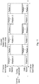
- a first pattern, Pattern 1 comprises radio resource bands at a first carrier band edge and, at a second subframe, at a second carrier band respectively.
- the frequency hopping is carried out over these to radio resource bands.
- a second pattern, Pattern 2 comprises radio resource bands at the second carrier band edge and, at the second subframe, at the first carrier band respectively.
- a third pattern, Pattern 3 comprises radio resource bands contiguous in frequency domain with the first pattern, Pattern 1.
- a fourth pattern, Pattern 4 comprise radio resource bands contiguous in frequency domain with the second pattern, Pattern 2.
- successive or following patterns of the first pattern such as the third and fourth pattern, occupy radio resources that are either progressively closer to the carrier center, or occupy a same frequency subband, but a different time instance than the radio resource bands of the first pattern.
- Each pattern periodically selects radio resources close to both band edges, in order to achieve the FH gain.
- the periodicity could be one subframe or several subframes.
- Each pattern is narrowband and does not exceed the bandwidth of the narrowest physical channel to be transmitted over the considered radio resources.
- the defined patterns are orthogonal to each other, i.e., they occupy different sets of radio resources.
- the different patterns are alsO referred to as the D2D bands.
- Example of embodiment 1 UL transmissions may happen in the band-center part (not shown in the picture) but indicated as a contiguous bandwidth not used by any of the patterns.
- the bandwidth for e.g. PUSCH is continuous and not fractioned, differently from prior art. This suits UL single-carrier allocations.
- the patterns may be allocated to different D2D connections between different communication devices.
- Pattern 1 may be allocated to a first D2D connection, Pattern 2 to a second D2D connection, Pattern 3 to a third D2D connection and Pattern 4 to a fourth D2D connection.
- the contiguous bandwidth is not used by any of the Patterns 1-4.
- the patterns employ radio resources with index x, e.g. '1' for the first pattern.
- the index 'x' defines the radio resources to use in a definition ⁇ k x ; N-1-t x ⁇ .
- N defines a number of radio resource blocks of the carrier band and function k x defines the margin to a first radio resource, e.g. a resource block, of the first pattern from a first carrier band edge and N-1-t x defines another radio resource.
- the radio resources may be numbered from 0-7.
- 't x ' defines the margin to a second carrier band edge, and x is the index indicating the pattern, e.g. the first pattern.
- k x is one RB and t x is two RB
- the radio resource band used for the first pattern is one RB at each of carrier band edge
- the contiguous bandwidth not used by the first pattern is three RBs between the third RB to the fifth RB.
- Index '1' ⁇ 1; 5 ⁇ indicated that the first radio resource band is the second RB or RB1 and the second radio resource band is the sixth RB or RB5.
- 'k x ' and 't x ' may be based on index of the first pattern.
- N eight RBs
- k 0 is one RB
- t 0 is two RBs
- k' x is one RB
- t' x is one RB
- the contiguous bandwidth not used by any of the pattern is one RB being the fourth RB.
- the index '3' would then define frequency hopping between the RBs ⁇ 2;4 ⁇ .
- rules are defined for radio resource allocation when the D2D channel has a bandwidth that is larger than the radio resource pattern bandwidth, i.e. the communication requires more than one pattern.
- multiple patterns that are contiguous in frequency domain may be combined to obtain a joint pattern of the required or desired bandwidth. It is sufficient to signal an index of the lowest pattern in the joint set of patterns when assigning radio resources as the communication devices 10,11 know what amount of radio resources are required, e.g., when D2D radio resources are assigned by a control node, such as the radio node 12.
- Fig. 10 discloses an embodiment wherein the pattern 1 and pattern 3, contiguous in frequency domain, are combined into a joint pattern.
- the first communication device 10 when the first communication device 10 selects a pattern for transmission, the first communication device 10 may perform the following steps:
- the first communication device 10 identifies the second pattern as an interference free pattern, the first pattern being occupied.
- the second pattern is thus considered as unused pattern with the lowest index, and this index is reported to be used to the second communication device 11 and/or the radio node 12.
- the properties of the patterns are exploited to reduce signaling and simplify detection of interfered patterns.
- the first communication device 10 When the first communication device 10 is tasked to report the available D2D radio resources to a control node or another communication device, such as the radio node 12, it performs the following actions:
- a pattern, such as the first pattern, of radio resource patterns for frequency hopping may be configured for two subbands at each carrier band edge, e.g. such that the first pattern occupies a first subband with a margin to the first carrier band edge and a second subband at the second carrier band edge and do not span a central portion of the carrier band. Still, the first pattern is given a hopping pattern such the D2D radio resources may span different subbands at different time instances within each of the two subbands. In other words, the first pattern may not be restricted to x: ⁇ k(x)x; N-1-tx(x) ⁇ . Hence, the first pattern or any pattern of the multiple patterns may occupy different frequency subbands at different time instances as long as the contiguous bandwidth is not used.
- a radio node is disclosed.
- Fig. 13 shows a block diagram depicting the radio node 12 for enabling communication between the first communication device 10 and the second communication device 11 over a D2D connection in the radio communications network 1 according to embodiments herein.
- the radio node 12 comprises processing means 1301 configured to allocate radio resource bands of a carrier band for the D2D connection according to at least a first pattern for frequency hopping, wherein the radio resource bands are used for frequency hopping over the carrier band and are at a respective carrier band edge and/or at the respective carrier band edge plus or minus a margin such that a contiguous bandwidth of radio resources between the radio resource bands is not used by the first pattern.
- the radio node 12 may e.g.
- the margin may be based on radio resource band of a control channel.
- the first pattern of multiple patterns employs radio resources with index x : k x ; N ⁇ 1 ⁇ t x , wherein N defines a number of radio resource blocks of the carrier band and function k x defines the margin to a first radio resource block of the first pattern from a first carrier band edge and N-1-t x defines another radio resource block wherein t x defines the margin to a second carrier band edge, and x is the index indicating the first pattern.
- k x and t x may be based on index of the first pattern.
- the radio resource bands of a successive or following pattern, such as pattern 2 to the first pattern occupy radio resource bands that occupy a same frequency subband, but at a different time instance than the radio resource bands of the first pattern.
- the radio resource bands of a successive or following pattern, such as pattern 3 to the first pattern occupy radio resource bands that are progressively closer to a center carrier of the carrier band than the radio resource bands of the first pattern.
- the processing means 1301 is further configured to signal an indication of the allocated radio resources to the first communication device 10 and/or the second communication device 11.
- the processing means 1301 may further be configured to signal an index, being the indication, of the first pattern to the first communication device 10 and/or the second communication device 11.
- the radio node 12 may comprise a signalling module 1303 configured to signal the indication such as the index.
- An uplink communication by the third communication device 14 to a radio node, such as the radio node 12 or another radio node, may use radio resources of the carrier band, and at least a fraction of the contiguous bandwidth is for an uplink channel.
- the processing means 1301 or the allocating module 1302 may further be configured to allocate one or more patterns that are contiguous in frequency domain with the first pattern and configured to combine one or more patterns with the first pattern to obtain a joint pattern of a desired bandwidth.
- the processing means 1301 or the signalling module 1303 may then further be configured to signal, to the first communication device 10 and/or second communication device 11, an index, being the indication, of the first pattern in the joint pattern with a lowest index when assigning radio resource bands.
- the radio node 12 may comprise a receiver, RX, 1304 and a transmitter, TX, 1305, e.g. a transceiver.
- the radio node 12 further comprises a memory 1306 configured to have data stored thereon, such as applications to perform the methods herein, patterns, channel information, signal information, radio resource information and/or the like.
- Fig. 14 shows a block diagram depicting the first communication device 10 for enabling communication between the first communication device 10 and the second communication device 11 over a D2D connection in the radio communications network 1.
- the first communication device 10 comprises processing means 1401 configured to obtain an indication of radio resource bands of a carrier band according to at least a first pattern for frequency hopping for the D2D connection.
- the radio resource bands are at a respective carrier band edge and/or at the respective carrier band edge plus or minus a margin such that a contiguous bandwidth of radio resources between the radio resource bands is not used by the first pattern.
- the first communication device 10 may comprise an obtaining module 1402 configured to obtain the first pattern, e.g. one or more patterns.
- the processing means 1401 may be configured to receive the indication from a radio node in the radio communications network, or to retrieve the indication from a memory within the first communication device 10.
- the obtaining module 1402 may be configured to receive the indication from a radio node in the radio communications network, or to retrieve the indication from a memory within the first communication device 10.
- the processing means 1401 is further configured to use the indication when setting up the D2D connection to the second communication device 11.
- the first communication device 10 may comprise a using module 1403 configured to use the indication to set up the D2D connection.
- the processing means 1401 may further be configured to obtain more than one pattern of radio resources bands and furthermore be configured to identify an interference-free pattern that is closest to the carrier band edges or with a lowest index among the patterns.
- the obtaining module 1402 may be configured to obtain more than one pattern and the first communication device 10 may comprise an identifying module 1404 configured to identify the interference free pattern.
- the processing means 1401 may then be configured to use the identified interference-free pattern to set up the D2D connection.
- the using module 1403 may be configured to use the interference free pattern.
- the processing means 1401 may be configured to obtain more than one pattern of radio resources bands, and further be configured to identify an interference-free pattern that is closest to the carrier band edges or with a lowest index among the radio resource bands. The processing means 1401 may then be configured to report the index of the identified interference-free pattern to the radio node 12 and/or the second communication device 11.
- the first communication device 10 may comprise a reporting module 1405 configured to report the index of the interference free pattern.
- the processing means 1401 may further be configured to determine amount of radio resources needed to transmit data. The processing means 1401 may then be configured to take the determined amount into account when setting up the D2D connection.
- the first communication device 10 may comprise a determining module 1406 configured to determine the amount radio resources needed and the using module 1403 may configured to use the determined amount when setting up the D2D connection.
- the processing means 1401, or the obtaining module 1402 may be configured to obtain a successive or following pattern that is contiguous in frequency domain with the first pattern, and to combine the successive or following pattern with the first pattern to obtain a joint pattern of a desired bandwidth.
- the processing means 1401 may further be configured to signal, to the second communication device 11 and/or the radio node 12, an index of the successive or following pattern in the joint pattern with a highest index, and/or an index of a pattern used in the D2D connection.
- the first communication device 10 may comprise a signalling module 1407 the index of a pattern used in the D2D connection and/or the successive or following pattern in the joint pattern with a highest index.
- the first communication device 10 may comprise a receiver, RX, 1408 and a transmitter, TX, 1409, e.g. a transceiver.
- the first communication device 10 further comprises a memory 1410 that may be configured to have data stored thereon, such as applications to perform the methods herein, patterns, channel information, signal information, radio resource information and/or the like.
- a second communication device is disclosed.
- Fig. 15 shows a block diagram depicting the second communication device 11 for enabling communication between the first communication device 10 and the second communication device 11 over a D2D connection in the radio communications network 1.
- the second communication device 11 comprises a processing means 1501 configured to obtain an indication of radio resource bands of a carrier band according to at least a first pattern for frequency hopping for the D2D connection.
- the radio resource bands are at a respective carrier band edge and/or at the respective carrier band edge plus or minus a margin such that a contiguous bandwidth of radio resources between the radio resource bands is not used by the first pattern.
- the second communication device 11 may comprise an obtaining module 1502 configured to obtain the first pattern, or one or more patterns.
- the processing means 1501 is configured to receive from the first communication device 10 and/or the radio node 12 an indication of radio resources of a pattern, such as the index of a pattern, used in the D2D connection.
- the second communication device 11 may comprise a receiving module 1503 configured to receive the indication.
- the processing means 1501 is configured to use the pattern indicated by the received index for communicating with the first communication device 10.
- the second communication device 11 may comprise a using module 1504 configured to use the pattern indicated by the received indication for communicating with the first communication device 10.
- the second communication device 11 may comprise a receiver, RX, 1505 and a transmitter, TX, 1506, e.g. a transceiver.
- the second communication device 11 further comprises a memory 1507 that may be configured to have data stored thereon, such as applications to perform the methods herein, patterns, channel information, signal information, radio resource information and/or the like.
- processors or “controller” as used herein does not exclusively refer to hardware capable of executing software and may implicitly include, without limitation, digital signal processor (DSP) hardware, read-only memory (ROM) for storing software, random-access memory for storing software and/or program or application data, and non-volatile memory.
- DSP digital signal processor
- ROM read-only memory
- RAM random-access memory
- non-volatile memory non-volatile memory
- Other hardware conventional and/or custom, may also be included. Designers of communications receivers and transmitters will appreciate the cost, performance, and maintenance trade-offs inherent in these design choices.
- the methods according to the embodiments described herein for the radio node 12, the first communication device 10 or the second communication device 11 are respectively implemented by means of e.g. a computer program 1307, 1411, 1508 or a computer program product, comprising instructions, i.e., software code portions, which, when executed on at least one processor, cause the at least one processor to carry out the actions described herein, as performed by the radio node 12, the first communication device 10 or the second communication device 11.
- the computer program 1307, 1411, 1508 may be stored on a computer-readable storage medium 1308, 1412, 1509, e.g. a disc or similar.
- the computer-readable storage medium 1308, 1412, 1509, having stored thereon the computer program, may comprise the instructions which, when executed on at least one processor, cause the at least one processor to carry out the actions described herein, as performed by the radio node 12, the first communication device 10 or the second communication device 11.
- the computer-readable storage medium may be a non-transitory computer-readable storage medium.
- the processing means herein may be implemented through one or more processors, together with computer program for performing the functions and/or method actions of the embodiments herein.
- the computer program mentioned above may also be provided for instance in the form of a data carrier carrying computer program code for performing embodiments herein when being loaded into nodes.
- a data carrier carrying computer program code for performing embodiments herein when being loaded into nodes.
- One such carrier may be in the form of a CD ROM disc. It is however feasible with other data carriers such as a memory stick.
- the computer program may furthermore be provided as pure program code on a server and downloaded to the nodes.
Landscapes
- Engineering & Computer Science (AREA)
- Computer Networks & Wireless Communication (AREA)
- Signal Processing (AREA)
- Quality & Reliability (AREA)
- Mobile Radio Communication Systems (AREA)
Claims (17)
- Verfahren für einen Funkknoten (12) zum Ermöglichen einer Kommunikation zwischen einer ersten Kommunikationsvorrichtung (10) und einer zweiten Kommunikationsvorrichtung (11) über eine Vorrichtung-zu-Vorrichtung-Verbindung (D2D-Verbindung) in einem Funkkommunikationsnetz (1), wobei das Verfahren Folgendes umfasst:- Zuordnen (202) von Funkressourcenbändern eines Trägerbandes für die D2D-Verbindung gemäß mindestens einem ersten Muster zum Frequenzspringen, wobei die Funkressourcenbänder zum Frequenzspringen über das Trägerband verwendet werden und an einer jeweiligen Trägerbandkante und/oder an der jeweiligen Trägerbandkante plus oder minus einem Bandbreitenbereich liegen, so dass eine zusammenhängende Bandbreite von Funkressourcen zwischen den Funkressourcenbändern nicht von dem ersten Muster verwendet wird; und- Signalisieren (203) einer Angabe der zugewiesenen Funkressourcenbänder an die erste Kommunikationsvorrichtung (10) und/oder die zweite Kommunikationsvorrichtung (11).
- Verfahren nach Anspruch 1, wobei das erste Muster von mehreren Mustern Funkressourcen mit dem Index x verwendet, wobei

- Verfahren nach Anspruch 2, wobei kx und tx auf dem Index des ersten Musters basieren.
- Verfahren nach einem der Ansprüche 2 bis 3, wobei kx und tx definiert sind als kx = k'x + k0 und tx = t'x + t0, wobei k'x und t'x Muster bestimmten und k0 und t0 gemeinsame Abstandswerte für mehrere Muster sind.
- Verfahren nach einem der Ansprüche 1 bis 4, wobei das Signalisieren (203) das Signalisieren eines Index' umfasst, der die Angabe des ersten Musters an die erste Kommunikationsvorrichtung (10) und/oder die zweite Kommunikationsvorrichtung (11) darstellt.
- Verfahren nach einem der Ansprüche 1 bis 5, wobei eine Uplink-Kommunikation durch eine dritte Kommunikationsvorrichtung (14) mit einem Funkknoten (12) Funkressourcen des Trägerbandes und mindestens einen Bruchteil der zusammenhängenden Bandbreite für einen Uplinkkanal verwendet.
- Verfahren nach einem der Ansprüche 1 bis 6, wobei die Funkressourcenbänder eines aufeinander folgenden oder folgenden Musters zu dem ersten Muster Funkressourcenbänder belegen, die dasselbe Frequenzunterband belegen, aber zu einer anderen Zeitinstanz als die Funkressourcenbänder des ersten Musters auftreten.
- Verfahren nach einem der Ansprüche 1 bis 7, wobei die Funkressourcenbänder eines aufeinander folgenden oder folgenden Musters zu dem ersten Muster Funkressourcenbänder belegen, die progressiv näher an einem Mittelträger des Trägerbandes liegen als die Funkressourcenbänder des ersten Musters.
- Verfahren für eine erste Kommunikationsvorrichtung (10) zum Ermöglichen einer Kommunikation zwischen der ersten Kommunikationsvorrichtung (10) und einer zweiten Kommunikationsvorrichtung (11) über eine Vorrichtung-zu-Vorrichtung-Verbindung (D2D-Verbindung) in einem Funkkommunikationsnetz (1); umfassend- Erhalten (401) einer Angabe von Funkressourcenbändern eines Trägerbandes gemäß mindestens einem ersten Muster zum Frequenzspringen für die D2D-Verbindung, wobei die Funkressourcenbänder an einer jeweiligen Trägerbandkante und/oder an der jeweiligen Trägerbandkante plus oder minus einem Bandbreitenbereich liegen, so dass eine zusammenhängende Bandbreite von Funkressourcen zwischen den Funkressourcenbändern nicht von dem ersten Muster verwendet wird; und- Verwenden (404) der Angabe, wenn die D2D-Verbindung zu der zweiten Kommunikationsvorrichtung (11) aufgebaut wird.
- Verfahren nach Anspruch 9, wobei das Erhalten () das Erhalten von Funkressourcenbändern von mehr als einem Muster von Funkbetriebsmittelbändern umfasst, und das Verfahren ferner Folgendes umfasst:- Identifizieren (402) eines störungsfreien Musters, das den Trägerbandkanten am nächsten ist, oder mit einem niedrigsten Index unter den Mustern; und wobei die Verwendung (404) die Nutzung des identifizierten störungsfreien Musters umfasst, um die D2D-Verbindung aufzubauen.
- Verfahren nach Anspruch 9, wobei das Erhalten (401) das Erhalten von Funkressourcenbändern von mehr als einem Muster von Funkbetriebsmittelbändern umfasst, und das Verfahren ferner Folgendes umfasst- Identifizieren (402) eines störungsfreien Musters, das den Trägerbandkanten am nächsten ist, oder mit einem niedrigsten Index unter den Mustern; und wobei das Verwenden (404) umfasst, einen Index des identifizierten störungsfreien Musters an einen Funkknoten (12) und/oder die zweite Kommunikationsvorrichtung (11) zu melden.
- Verfahren nach einem der Ansprüche 9 bis 11, ferner umfassend- Bestimmen (403) der Menge an Funkressourcen, die zum Übertragen von Daten benötigt werden, und Verwenden (404) unter Berücksichtigung der bestimmten Menge.
- Verfahren nach einem der Ansprüche 9 bis 12, wobei das Erhalten (401) umfasst, dass ein aufeinander folgendes oder nachfolgendes Muster, das im Frequenzbereich mit dem ersten Muster zusammenhängend ist, und das Verwenden (404) umfasst, das aufeinander folgende oder nachfolgende Muster mit dem ersten Muster so zu kombinieren, dass ein gemeinsames Muster einer gewünschten Bandbreite erhalten wird.
- Verfahren für eine zweite Kommunikationsvorrichtung (11) zum Ermöglichen einer Kommunikation zwischen einer ersten Kommunikationsvorrichtung (10) und der zweiten Kommunikationsvorrichtung (11) über eine Vorrichtung-zu-Vorrichtung-Verbindung (D2D-Verbindung) in einem Funkkommunikationsnetz; umfassend- Erhalten (601) einer Angabe von Funkressourcenbändern eines Trägerbandes gemäß mindestens einem ersten Muster zum Frequenzspringen für die D2D-Verbindung, wobei die Funkressourcenbänder an einer jeweiligen Trägerbandkante und/oder an der jeweiligen Trägerbandkante plus oder minus einem Bandbreitenbereich liegen, so dass eine zusammenhängende Bandbreite von Funkressourcen zwischen den Funkressourcenbändern nicht von dem ersten Muster verwendet wird;- Empfangen (602) einer Angabe von Funkressourcenbändern eines in der D2D-Verbindung verwendeten Musters von der ersten Kommunikationsvorrichtung (10) und/oder einem Funkknoten (12); und- Verwenden (603) des Musters, das durch den empfangenen Index zur Kommunikation mit der ersten Kommunikationsvorrichtung (10) angegeben wird.
- Funkknoten (12) zum Ermöglichen einer Kommunikation zwischen einer ersten Kommunikationsvorrichtung (10) und einer zweiten Kommunikationsvorrichtung (11) über eine Vorrichtung-zu-Vorrichtung-Verbindung (D2D-Verbindung) in einem Funkkommunikationsnetz (1), wobei der Funkknoten (12) Verarbeitungsmittel (1301) umfasst, die so konfiguriert sind, dass sie:- Funkressourcenbänder eines Trägerbandes für die D2D-Verbindung gemäß mindestens einem ersten Muster zum Frequenzspringen zuweisen, wobei die Funkressourcenbänder zum Frequenzspringen über das Trägerband verwendet werden und an einer jeweiligen Trägerbandkante und/oder der jeweiligen Trägerbandkante plus oder minus einem Bandbreitenbereich liegen, so dass eine zusammenhängende Bandbreite von Funkressourcen zwischen den Funkressourcenbändern nicht von dem ersten Muster verwendet wird; und
eine Angabe der zugewiesenen Funkressourcenbänder an die erste Kommunikationsvorrichtung (10) und/oder die zweite Kommunikationsvorrichtung (11) signalisieren. - Erste Kommunikationsvorrichtung (10) zum Ermöglichen einer Kommunikation zwischen der ersten Kommunikationsvorrichtung (10) und einer zweiten Kommunikationsvorrichtung (11) über eine Vorrichtung-zu-Vorrichtung-Verbindung (D2D-Verbindung) in einem Funkkommunikationsnetz (1); die Verarbeitungsmittel (1401) umfasst, die so konfiguriert sind, dass sie eine Angabe von Funkressourcenbändern eines Trägerbandes gemäß mindestens einem ersten Muster zum Frequenzspringen für die D2D- Verbindung erhalten, wobei die Funkressourcenbänder an einer jeweiligen Trägerbandkante und/oder an der jeweiligen Trägerbandkante plus oder minus einem Bandbreitenbereich liegen, so dass eine zusammenhängende Bandbreite von Funkressourcen zwischen den Funkressourcenbändern nicht von dem ersten Muster verwendet wird; und
die Angabe verwenden, wenn die D2D-Verbindung mit der zweiten Kommunikationsvorrichtung (11) aufgebaut wird. - Zweite Kommunikationsvorrichtung (11) zum Ermöglichen einer Kommunikation zwischen einer ersten Kommunikationsvorrichtung (10) und der zweiten Kommunikationsvorrichtung (11) über eine Vorrichtung-zu-Vorrichtung-Verbindung (D2D-Verbindung) in einem Funkkommunikationsnetz (1), die Verarbeitungsmittel umfasst (1501), die so konfiguriert sind dass sie:eine Angabe von Funkressourcenbändern eines Trägerbandes gemäß mindestens einem ersten Muster zum Frequenzspringen für die D2D Verbindung erhalten, wobei die Funkressourcenbänder an einer jeweiligen Trägerbandkante und/oder an der jeweiligen Trägerbandkante plus oder minus einem Bandbreitenbereich liegen, so dass eine zusammenhängende Bandbreite von Funkressourcen zwischen den Funkressourcenbändern nicht von dem ersten Muster verwendet wird;eine Angabe von Funkressourcen eines in der D2D-Verbindung verwendeten Musters von der ersten Kommunikationsvorrichtung (10) und/oder einem Funkknoten (12) empfangen; unddas durch die empfangene Angabe angegebene Muster zur Kommunikation mit der ersten Kommunikationsvorrichtung (10) verwenden.
Applications Claiming Priority (1)
| Application Number | Priority Date | Filing Date | Title |
|---|---|---|---|
| PCT/SE2014/050127 WO2015115951A1 (en) | 2014-01-31 | 2014-01-31 | Radio node, communication devices and methods therein |
Publications (3)
| Publication Number | Publication Date |
|---|---|
| EP3100570A1 EP3100570A1 (de) | 2016-12-07 |
| EP3100570A4 EP3100570A4 (de) | 2017-10-18 |
| EP3100570B1 true EP3100570B1 (de) | 2018-10-31 |
Family
ID=53757408
Family Applications (1)
| Application Number | Title | Priority Date | Filing Date |
|---|---|---|---|
| EP14881120.1A Not-in-force EP3100570B1 (de) | 2014-01-31 | 2014-01-31 | Funkknoten, kommunikationsvorrichtungen und verfahren darin |
Country Status (6)
| Country | Link |
|---|---|
| US (1) | US10142990B2 (de) |
| EP (1) | EP3100570B1 (de) |
| CN (1) | CN105960828A (de) |
| MX (1) | MX358767B (de) |
| PH (1) | PH12016501413A1 (de) |
| WO (1) | WO2015115951A1 (de) |
Families Citing this family (10)
| Publication number | Priority date | Publication date | Assignee | Title |
|---|---|---|---|---|
| US10419175B2 (en) * | 2014-03-20 | 2019-09-17 | Lg Electronics Inc. | Method for transmitting D2D signal in wireless communication system and device therefor |
| CN105940731B (zh) * | 2014-04-14 | 2019-03-01 | 夏普株式会社 | 终端装置及其无线通信方法、基站装置及其无线通信方法 |
| CN104202740B (zh) * | 2014-05-08 | 2019-07-19 | 中兴通讯股份有限公司 | 通信数据发送方法、装置及用户设备 |
| JP6461309B2 (ja) * | 2014-08-20 | 2019-01-30 | エルジー エレクトロニクス インコーポレイティド | 無線通信システムにおいて信号伝送方法及び装置 |
| EP3190844B1 (de) * | 2014-09-26 | 2019-07-24 | Huawei Technologies Co., Ltd. | D2d-signalfrequenzsprungverfahren und basisstation |
| WO2018027989A1 (zh) * | 2016-08-12 | 2018-02-15 | 华为技术有限公司 | 一种通信方法和装置 |
| CN109729584B (zh) * | 2017-10-27 | 2022-06-10 | 成都鼎桥通信技术有限公司 | 非对称上行载波聚合的上行带宽压缩方法及装置 |
| EP3753115A1 (de) * | 2018-02-16 | 2020-12-23 | Telefonaktiebolaget Lm Ericsson (Publ) | Frequenzsprungzuweisung für gemeinsam genutzten physischen uplink-kanal (pusch) |
| CN112118625B (zh) * | 2019-06-19 | 2023-03-24 | 中国电信股份有限公司 | 上行数据信道的传输方法、设备和系统 |
| KR20240049379A (ko) * | 2021-08-31 | 2024-04-16 | 후아웨이 테크놀러지 컴퍼니 리미티드 | 통신 방법 및 장치 |
Family Cites Families (21)
| Publication number | Priority date | Publication date | Assignee | Title |
|---|---|---|---|---|
| US9374131B2 (en) * | 2009-01-28 | 2016-06-21 | Qualcomm Incorporated | Frequency hopping in a wireless communication network |
| EP2510733A4 (de) | 2009-12-11 | 2017-05-17 | Nokia Technologies Oy | Verfahren, vorrichtung und computerprogrammprodukt für die ressourcenzuweisung in drahtlosen kommunikationsnetzen |
| US8526347B2 (en) * | 2010-06-10 | 2013-09-03 | Qualcomm Incorporated | Peer-to-peer communication with symmetric waveform for downlink and uplink |
| EP2651047B1 (de) * | 2010-12-07 | 2017-08-30 | LG Electronics Inc. | Verfahren und vorrichtung zur kommunikation zwischen endgeräten in einem drahtlosen kommunikationssystem |
| CN103002578B (zh) * | 2011-09-08 | 2016-06-22 | 中国移动通信集团公司 | 在蜂窝网络中实现d2d数据传输的方法、装置及系统 |
| CN103108405B (zh) * | 2011-11-15 | 2017-09-08 | 中兴通讯股份有限公司 | 无线通信方法和系统 |
| US9461766B2 (en) * | 2012-03-09 | 2016-10-04 | Lg Electronics Inc. | Method and apparatus for setting reference signal |
| WO2013137699A1 (ko) * | 2012-03-16 | 2013-09-19 | 엘지전자 주식회사 | 상향 링크 전송 방법 및 장치 |
| GB2501088B (en) * | 2012-04-11 | 2014-11-12 | Broadcom Corp | Methods and apparatus for transmitting and/or controlling device-to-device discovery signals |
| US9143984B2 (en) * | 2012-04-13 | 2015-09-22 | Intel Corporation | Mapping of enhanced physical downlink control channels in a wireless communication network |
| WO2013162333A1 (ko) * | 2012-04-26 | 2013-10-31 | 한국전자통신연구원 | 부분적 단말 제어 단말 대 단말 통신 방법 |
| US9485794B2 (en) | 2012-05-23 | 2016-11-01 | Qualcomm Incorporated | Methods and apparatus for using device to device communications to support IMS based services |
| US9768939B2 (en) * | 2012-06-18 | 2017-09-19 | Lg Electronics Inc. | Signal transmission/reception method and apparatus therefor |
| HUE054341T2 (hu) * | 2012-07-06 | 2021-08-30 | Ericsson Telefon Ab L M | Felfedezõ jelek adására való adó, vevõ és az abban alkalmazott eljárások |
| CN103716841A (zh) * | 2012-09-29 | 2014-04-09 | 中兴通讯股份有限公司 | 信息传输方法及装置 |
| EP2904864B1 (de) * | 2012-10-05 | 2019-09-18 | Sierra Wireless, Inc. | Verfahren und system zur uplink-funkressourcenzuweisung in einem lte-kommunikationssystem |
| US9326121B2 (en) * | 2013-01-24 | 2016-04-26 | National Taiwan University | Device discovery using distributed random access for device to device communication |
| US9173200B2 (en) * | 2013-02-28 | 2015-10-27 | Intel Mobile Communications GmbH | Communication terminal, network component, base station and method for communicating |
| US9713124B2 (en) * | 2013-07-12 | 2017-07-18 | Lg Electronics Inc. | Method and apparatus for transmitting signal in wireless communication system |
| CN110635889B (zh) * | 2013-08-06 | 2022-06-10 | 太阳专利信托公司 | 发送装置、接收装置、通信方法及集成电路 |
| US9521675B2 (en) * | 2013-12-16 | 2016-12-13 | Qualcomm Incorporated | Opportunistically utilizing media resources |
-
2014
- 2014-01-31 EP EP14881120.1A patent/EP3100570B1/de not_active Not-in-force
- 2014-01-31 CN CN201480074374.6A patent/CN105960828A/zh active Pending
- 2014-01-31 MX MX2016009833A patent/MX358767B/es active IP Right Grant
- 2014-01-31 WO PCT/SE2014/050127 patent/WO2015115951A1/en not_active Ceased
- 2014-01-31 US US15/114,965 patent/US10142990B2/en active Active
-
2016
- 2016-07-18 PH PH12016501413A patent/PH12016501413A1/en unknown
Non-Patent Citations (1)
| Title |
|---|
| None * |
Also Published As
| Publication number | Publication date |
|---|---|
| MX358767B (es) | 2018-09-03 |
| US20170048856A1 (en) | 2017-02-16 |
| EP3100570A1 (de) | 2016-12-07 |
| PH12016501413A1 (en) | 2016-08-22 |
| CN105960828A (zh) | 2016-09-21 |
| EP3100570A4 (de) | 2017-10-18 |
| US10142990B2 (en) | 2018-11-27 |
| WO2015115951A1 (en) | 2015-08-06 |
| MX2016009833A (es) | 2016-10-26 |
Similar Documents
| Publication | Publication Date | Title |
|---|---|---|
| EP3100570B1 (de) | Funkknoten, kommunikationsvorrichtungen und verfahren darin | |
| JP7334175B2 (ja) | ニューラジオアンライセンスト(nr-u)におけるサブバンドアクセスのための帯域幅部分(bwp)構成 | |
| JP7822980B2 (ja) | マシンタイプ通信のためのサブ物理リソースブロックリソース割振りのための技法および装置 | |
| EP3905840B1 (de) | Signalanzeige für flexible koexistenz von new radio (nr) und long term evolution (lte) | |
| EP3404985A1 (de) | Vollduplex-downlink- und uplink-anweisungen | |
| CN111095977A (zh) | 用于csi-rs端口子集指示的方法和装置 | |
| CN110892665B (zh) | 物理上行链路控制信道(pucch)序列配置 | |
| CN105338634B (zh) | 资源调度方法、基站和用户设备 | |
| WO2015166801A1 (ja) | 基地局装置、端末装置、および通信方法 | |
| US12381671B2 (en) | Selective suppression of uplink transmission in control regions | |
| EP3675580B1 (de) | Vorrichtung und verfahren zur ressourcenverwaltung in einem drahtloskommunikationssystem | |
| CN113940127A (zh) | 用于nr-u的基于子带的资源分配的技术 | |
| US20180198582A1 (en) | Radio Network Node, Wireless Device and Methods Performed Therein | |
| US20170064561A1 (en) | Base-station apparatus, terminal apparatus, and communication method | |
| CN112997412B (zh) | 用于信令通知跳变传输的方法和装置 | |
| CN112740801A (zh) | 用于对使用非相干联合传输的不同类型的话务的dl复用的先占指示 | |
| CN119014076A (zh) | 无线通信的方法和终端设备 | |
| US20220278783A1 (en) | Base station, method, program, and recording medium | |
| HK40017949A (en) | Techniques and apparatuses for sub-physical resource block resource allocation for machine type communication | |
| HK40017949B (en) | Techniques and apparatuses for sub-physical resource block resource allocation for machine type communication |
Legal Events
| Date | Code | Title | Description |
|---|---|---|---|
| PUAI | Public reference made under article 153(3) epc to a published international application that has entered the european phase |
Free format text: ORIGINAL CODE: 0009012 |
|
| STAA | Information on the status of an ep patent application or granted ep patent |
Free format text: STATUS: REQUEST FOR EXAMINATION WAS MADE |
|
| 17P | Request for examination filed |
Effective date: 20160825 |
|
| AK | Designated contracting states |
Kind code of ref document: A1 Designated state(s): AL AT BE BG CH CY CZ DE DK EE ES FI FR GB GR HR HU IE IS IT LI LT LU LV MC MK MT NL NO PL PT RO RS SE SI SK SM TR |
|
| AX | Request for extension of the european patent |
Extension state: BA ME |
|
| DAX | Request for extension of the european patent (deleted) | ||
| A4 | Supplementary search report drawn up and despatched |
Effective date: 20170920 |
|
| RIC1 | Information provided on ipc code assigned before grant |
Ipc: H04W 72/04 20090101ALI20170914BHEP Ipc: H04W 72/08 20090101ALI20170914BHEP Ipc: H04B 1/69 20110101ALI20170914BHEP Ipc: H04W 76/02 20090101AFI20170914BHEP |
|
| REG | Reference to a national code |
Ref country code: DE Ref legal event code: R079 Ref document number: 602014035377 Country of ref document: DE Free format text: PREVIOUS MAIN CLASS: H04W0076020000 Ipc: H04W0072080000 |
|
| GRAP | Despatch of communication of intention to grant a patent |
Free format text: ORIGINAL CODE: EPIDOSNIGR1 |
|
| STAA | Information on the status of an ep patent application or granted ep patent |
Free format text: STATUS: GRANT OF PATENT IS INTENDED |
|
| RIC1 | Information provided on ipc code assigned before grant |
Ipc: H04W 72/08 20090101AFI20180502BHEP Ipc: H04W 72/04 20090101ALI20180502BHEP |
|
| INTG | Intention to grant announced |
Effective date: 20180523 |
|
| GRAS | Grant fee paid |
Free format text: ORIGINAL CODE: EPIDOSNIGR3 |
|
| GRAA | (expected) grant |
Free format text: ORIGINAL CODE: 0009210 |
|
| STAA | Information on the status of an ep patent application or granted ep patent |
Free format text: STATUS: THE PATENT HAS BEEN GRANTED |
|
| AK | Designated contracting states |
Kind code of ref document: B1 Designated state(s): AL AT BE BG CH CY CZ DE DK EE ES FI FR GB GR HR HU IE IS IT LI LT LU LV MC MK MT NL NO PL PT RO RS SE SI SK SM TR |
|
| REG | Reference to a national code |
Ref country code: CH Ref legal event code: EP Ref country code: GB Ref legal event code: FG4D |
|
| REG | Reference to a national code |
Ref country code: AT Ref legal event code: REF Ref document number: 1060930 Country of ref document: AT Kind code of ref document: T Effective date: 20181115 |
|
| REG | Reference to a national code |
Ref country code: IE Ref legal event code: FG4D |
|
| REG | Reference to a national code |
Ref country code: DE Ref legal event code: R096 Ref document number: 602014035377 Country of ref document: DE |
|
| REG | Reference to a national code |
Ref country code: NL Ref legal event code: MP Effective date: 20181031 |
|
| REG | Reference to a national code |
Ref country code: LT Ref legal event code: MG4D |
|
| REG | Reference to a national code |
Ref country code: AT Ref legal event code: MK05 Ref document number: 1060930 Country of ref document: AT Kind code of ref document: T Effective date: 20181031 |
|
| PG25 | Lapsed in a contracting state [announced via postgrant information from national office to epo] |
Ref country code: IS Free format text: LAPSE BECAUSE OF FAILURE TO SUBMIT A TRANSLATION OF THE DESCRIPTION OR TO PAY THE FEE WITHIN THE PRESCRIBED TIME-LIMIT Effective date: 20190228 Ref country code: ES Free format text: LAPSE BECAUSE OF FAILURE TO SUBMIT A TRANSLATION OF THE DESCRIPTION OR TO PAY THE FEE WITHIN THE PRESCRIBED TIME-LIMIT Effective date: 20181031 Ref country code: HR Free format text: LAPSE BECAUSE OF FAILURE TO SUBMIT A TRANSLATION OF THE DESCRIPTION OR TO PAY THE FEE WITHIN THE PRESCRIBED TIME-LIMIT Effective date: 20181031 Ref country code: LV Free format text: LAPSE BECAUSE OF FAILURE TO SUBMIT A TRANSLATION OF THE DESCRIPTION OR TO PAY THE FEE WITHIN THE PRESCRIBED TIME-LIMIT Effective date: 20181031 Ref country code: BG Free format text: LAPSE BECAUSE OF FAILURE TO SUBMIT A TRANSLATION OF THE DESCRIPTION OR TO PAY THE FEE WITHIN THE PRESCRIBED TIME-LIMIT Effective date: 20190131 Ref country code: FI Free format text: LAPSE BECAUSE OF FAILURE TO SUBMIT A TRANSLATION OF THE DESCRIPTION OR TO PAY THE FEE WITHIN THE PRESCRIBED TIME-LIMIT Effective date: 20181031 Ref country code: LT Free format text: LAPSE BECAUSE OF FAILURE TO SUBMIT A TRANSLATION OF THE DESCRIPTION OR TO PAY THE FEE WITHIN THE PRESCRIBED TIME-LIMIT Effective date: 20181031 Ref country code: PL Free format text: LAPSE BECAUSE OF FAILURE TO SUBMIT A TRANSLATION OF THE DESCRIPTION OR TO PAY THE FEE WITHIN THE PRESCRIBED TIME-LIMIT Effective date: 20181031 Ref country code: AT Free format text: LAPSE BECAUSE OF FAILURE TO SUBMIT A TRANSLATION OF THE DESCRIPTION OR TO PAY THE FEE WITHIN THE PRESCRIBED TIME-LIMIT Effective date: 20181031 Ref country code: NO Free format text: LAPSE BECAUSE OF FAILURE TO SUBMIT A TRANSLATION OF THE DESCRIPTION OR TO PAY THE FEE WITHIN THE PRESCRIBED TIME-LIMIT Effective date: 20190131 |
|
| PG25 | Lapsed in a contracting state [announced via postgrant information from national office to epo] |
Ref country code: SE Free format text: LAPSE BECAUSE OF FAILURE TO SUBMIT A TRANSLATION OF THE DESCRIPTION OR TO PAY THE FEE WITHIN THE PRESCRIBED TIME-LIMIT Effective date: 20181031 Ref country code: GR Free format text: LAPSE BECAUSE OF FAILURE TO SUBMIT A TRANSLATION OF THE DESCRIPTION OR TO PAY THE FEE WITHIN THE PRESCRIBED TIME-LIMIT Effective date: 20190201 Ref country code: NL Free format text: LAPSE BECAUSE OF FAILURE TO SUBMIT A TRANSLATION OF THE DESCRIPTION OR TO PAY THE FEE WITHIN THE PRESCRIBED TIME-LIMIT Effective date: 20181031 Ref country code: RS Free format text: LAPSE BECAUSE OF FAILURE TO SUBMIT A TRANSLATION OF THE DESCRIPTION OR TO PAY THE FEE WITHIN THE PRESCRIBED TIME-LIMIT Effective date: 20181031 Ref country code: PT Free format text: LAPSE BECAUSE OF FAILURE TO SUBMIT A TRANSLATION OF THE DESCRIPTION OR TO PAY THE FEE WITHIN THE PRESCRIBED TIME-LIMIT Effective date: 20190301 Ref country code: AL Free format text: LAPSE BECAUSE OF FAILURE TO SUBMIT A TRANSLATION OF THE DESCRIPTION OR TO PAY THE FEE WITHIN THE PRESCRIBED TIME-LIMIT Effective date: 20181031 |
|
| PG25 | Lapsed in a contracting state [announced via postgrant information from national office to epo] |
Ref country code: CZ Free format text: LAPSE BECAUSE OF FAILURE TO SUBMIT A TRANSLATION OF THE DESCRIPTION OR TO PAY THE FEE WITHIN THE PRESCRIBED TIME-LIMIT Effective date: 20181031 Ref country code: IT Free format text: LAPSE BECAUSE OF FAILURE TO SUBMIT A TRANSLATION OF THE DESCRIPTION OR TO PAY THE FEE WITHIN THE PRESCRIBED TIME-LIMIT Effective date: 20181031 Ref country code: DK Free format text: LAPSE BECAUSE OF FAILURE TO SUBMIT A TRANSLATION OF THE DESCRIPTION OR TO PAY THE FEE WITHIN THE PRESCRIBED TIME-LIMIT Effective date: 20181031 |
|
| REG | Reference to a national code |
Ref country code: DE Ref legal event code: R097 Ref document number: 602014035377 Country of ref document: DE Ref country code: DE Ref legal event code: R119 Ref document number: 602014035377 Country of ref document: DE |
|
| PG25 | Lapsed in a contracting state [announced via postgrant information from national office to epo] |
Ref country code: SM Free format text: LAPSE BECAUSE OF FAILURE TO SUBMIT A TRANSLATION OF THE DESCRIPTION OR TO PAY THE FEE WITHIN THE PRESCRIBED TIME-LIMIT Effective date: 20181031 Ref country code: SK Free format text: LAPSE BECAUSE OF FAILURE TO SUBMIT A TRANSLATION OF THE DESCRIPTION OR TO PAY THE FEE WITHIN THE PRESCRIBED TIME-LIMIT Effective date: 20181031 Ref country code: MC Free format text: LAPSE BECAUSE OF FAILURE TO SUBMIT A TRANSLATION OF THE DESCRIPTION OR TO PAY THE FEE WITHIN THE PRESCRIBED TIME-LIMIT Effective date: 20181031 Ref country code: EE Free format text: LAPSE BECAUSE OF FAILURE TO SUBMIT A TRANSLATION OF THE DESCRIPTION OR TO PAY THE FEE WITHIN THE PRESCRIBED TIME-LIMIT Effective date: 20181031 Ref country code: RO Free format text: LAPSE BECAUSE OF FAILURE TO SUBMIT A TRANSLATION OF THE DESCRIPTION OR TO PAY THE FEE WITHIN THE PRESCRIBED TIME-LIMIT Effective date: 20181031 |
|
| REG | Reference to a national code |
Ref country code: CH Ref legal event code: PL |
|
| PLBE | No opposition filed within time limit |
Free format text: ORIGINAL CODE: 0009261 |
|
| STAA | Information on the status of an ep patent application or granted ep patent |
Free format text: STATUS: NO OPPOSITION FILED WITHIN TIME LIMIT |
|
| GBPC | Gb: european patent ceased through non-payment of renewal fee |
Effective date: 20190131 |
|
| PG25 | Lapsed in a contracting state [announced via postgrant information from national office to epo] |
Ref country code: LU Free format text: LAPSE BECAUSE OF NON-PAYMENT OF DUE FEES Effective date: 20190131 |
|
| 26N | No opposition filed |
Effective date: 20190801 |
|
| REG | Reference to a national code |
Ref country code: BE Ref legal event code: MM Effective date: 20190131 |
|
| REG | Reference to a national code |
Ref country code: IE Ref legal event code: MM4A |
|
| PG25 | Lapsed in a contracting state [announced via postgrant information from national office to epo] |
Ref country code: SI Free format text: LAPSE BECAUSE OF FAILURE TO SUBMIT A TRANSLATION OF THE DESCRIPTION OR TO PAY THE FEE WITHIN THE PRESCRIBED TIME-LIMIT Effective date: 20181031 Ref country code: FR Free format text: LAPSE BECAUSE OF NON-PAYMENT OF DUE FEES Effective date: 20190131 Ref country code: DE Free format text: LAPSE BECAUSE OF NON-PAYMENT OF DUE FEES Effective date: 20190801 |
|
| PG25 | Lapsed in a contracting state [announced via postgrant information from national office to epo] |
Ref country code: BE Free format text: LAPSE BECAUSE OF NON-PAYMENT OF DUE FEES Effective date: 20190131 |
|
| PG25 | Lapsed in a contracting state [announced via postgrant information from national office to epo] |
Ref country code: LI Free format text: LAPSE BECAUSE OF NON-PAYMENT OF DUE FEES Effective date: 20190131 Ref country code: CH Free format text: LAPSE BECAUSE OF NON-PAYMENT OF DUE FEES Effective date: 20190131 Ref country code: GB Free format text: LAPSE BECAUSE OF NON-PAYMENT OF DUE FEES Effective date: 20190131 |
|
| PG25 | Lapsed in a contracting state [announced via postgrant information from national office to epo] |
Ref country code: IE Free format text: LAPSE BECAUSE OF NON-PAYMENT OF DUE FEES Effective date: 20190131 |
|
| PG25 | Lapsed in a contracting state [announced via postgrant information from national office to epo] |
Ref country code: TR Free format text: LAPSE BECAUSE OF FAILURE TO SUBMIT A TRANSLATION OF THE DESCRIPTION OR TO PAY THE FEE WITHIN THE PRESCRIBED TIME-LIMIT Effective date: 20181031 |
|
| PG25 | Lapsed in a contracting state [announced via postgrant information from national office to epo] |
Ref country code: MT Free format text: LAPSE BECAUSE OF NON-PAYMENT OF DUE FEES Effective date: 20190131 |
|
| PG25 | Lapsed in a contracting state [announced via postgrant information from national office to epo] |
Ref country code: CY Free format text: LAPSE BECAUSE OF FAILURE TO SUBMIT A TRANSLATION OF THE DESCRIPTION OR TO PAY THE FEE WITHIN THE PRESCRIBED TIME-LIMIT Effective date: 20181031 |
|
| PG25 | Lapsed in a contracting state [announced via postgrant information from national office to epo] |
Ref country code: HU Free format text: LAPSE BECAUSE OF FAILURE TO SUBMIT A TRANSLATION OF THE DESCRIPTION OR TO PAY THE FEE WITHIN THE PRESCRIBED TIME-LIMIT; INVALID AB INITIO Effective date: 20140131 |
|
| PG25 | Lapsed in a contracting state [announced via postgrant information from national office to epo] |
Ref country code: MK Free format text: LAPSE BECAUSE OF FAILURE TO SUBMIT A TRANSLATION OF THE DESCRIPTION OR TO PAY THE FEE WITHIN THE PRESCRIBED TIME-LIMIT Effective date: 20181031 |