EP3100331B1 - Procédé de réglage de tension dans un réseau de courant continu à haute tension (hvdc) - Google Patents
Procédé de réglage de tension dans un réseau de courant continu à haute tension (hvdc) Download PDFInfo
- Publication number
- EP3100331B1 EP3100331B1 EP14714614.6A EP14714614A EP3100331B1 EP 3100331 B1 EP3100331 B1 EP 3100331B1 EP 14714614 A EP14714614 A EP 14714614A EP 3100331 B1 EP3100331 B1 EP 3100331B1
- Authority
- EP
- European Patent Office
- Prior art keywords
- voltage
- modification
- power set
- set value
- condition
- Prior art date
- Legal status (The legal status is an assumption and is not a legal conclusion. Google has not performed a legal analysis and makes no representation as to the accuracy of the status listed.)
- Active
Links
- 230000033228 biological regulation Effects 0.000 title description 8
- 238000000034 method Methods 0.000 claims description 30
- 230000004048 modification Effects 0.000 claims description 26
- 238000012986 modification Methods 0.000 claims description 26
- 238000001514 detection method Methods 0.000 claims description 6
- 230000001105 regulatory effect Effects 0.000 claims description 5
- 230000002123 temporal effect Effects 0.000 claims description 2
- 238000005259 measurement Methods 0.000 description 7
- 238000004891 communication Methods 0.000 description 6
- 238000010586 diagram Methods 0.000 description 4
- 230000007246 mechanism Effects 0.000 description 4
- 230000009467 reduction Effects 0.000 description 3
- 230000005540 biological transmission Effects 0.000 description 2
- 238000013461 design Methods 0.000 description 2
- 230000003213 activating effect Effects 0.000 description 1
- 230000000903 blocking effect Effects 0.000 description 1
- 230000001276 controlling effect Effects 0.000 description 1
- 230000001419 dependent effect Effects 0.000 description 1
- 238000011161 development Methods 0.000 description 1
- 230000018109 developmental process Effects 0.000 description 1
- 230000000694 effects Effects 0.000 description 1
- 238000005516 engineering process Methods 0.000 description 1
- 230000008676 import Effects 0.000 description 1
- 238000012544 monitoring process Methods 0.000 description 1
- 238000012913 prioritisation Methods 0.000 description 1
- 230000008569 process Effects 0.000 description 1
- 230000001960 triggered effect Effects 0.000 description 1
Images

Classifications
-
- H—ELECTRICITY
- H02—GENERATION; CONVERSION OR DISTRIBUTION OF ELECTRIC POWER
- H02J—CIRCUIT ARRANGEMENTS OR SYSTEMS FOR SUPPLYING OR DISTRIBUTING ELECTRIC POWER; SYSTEMS FOR STORING ELECTRIC ENERGY
- H02J3/00—Circuit arrangements for ac mains or ac distribution networks
- H02J3/36—Arrangements for transfer of electric power between ac networks via a high-tension dc link
-
- H—ELECTRICITY
- H02—GENERATION; CONVERSION OR DISTRIBUTION OF ELECTRIC POWER
- H02J—CIRCUIT ARRANGEMENTS OR SYSTEMS FOR SUPPLYING OR DISTRIBUTING ELECTRIC POWER; SYSTEMS FOR STORING ELECTRIC ENERGY
- H02J3/00—Circuit arrangements for ac mains or ac distribution networks
- H02J3/38—Arrangements for parallely feeding a single network by two or more generators, converters or transformers
-
- H—ELECTRICITY
- H02—GENERATION; CONVERSION OR DISTRIBUTION OF ELECTRIC POWER
- H02J—CIRCUIT ARRANGEMENTS OR SYSTEMS FOR SUPPLYING OR DISTRIBUTING ELECTRIC POWER; SYSTEMS FOR STORING ELECTRIC ENERGY
- H02J1/00—Circuit arrangements for dc mains or dc distribution networks
- H02J1/10—Parallel operation of dc sources
- H02J1/102—Parallel operation of dc sources being switching converters
-
- Y—GENERAL TAGGING OF NEW TECHNOLOGICAL DEVELOPMENTS; GENERAL TAGGING OF CROSS-SECTIONAL TECHNOLOGIES SPANNING OVER SEVERAL SECTIONS OF THE IPC; TECHNICAL SUBJECTS COVERED BY FORMER USPC CROSS-REFERENCE ART COLLECTIONS [XRACs] AND DIGESTS
- Y02—TECHNOLOGIES OR APPLICATIONS FOR MITIGATION OR ADAPTATION AGAINST CLIMATE CHANGE
- Y02E—REDUCTION OF GREENHOUSE GAS [GHG] EMISSIONS, RELATED TO ENERGY GENERATION, TRANSMISSION OR DISTRIBUTION
- Y02E60/00—Enabling technologies; Technologies with a potential or indirect contribution to GHG emissions mitigation
- Y02E60/60—Arrangements for transfer of electric power between AC networks or generators via a high voltage DC link [HVCD]
Definitions
- the present invention relates to a method for regulating voltage in a multi-terminal HVDC network system and more particularly to a method for handling over-voltages and under-voltages in a multi-terminal HVDC network managed independently by converter stations of the HVDC network.
- HVDC lines are widely used to move power across huge distances between grids.
- Current developments in the field of HVDC technology are based on DC grids with more than two converter stations, which can operate in both rectifier mode and inverter mode. These networks are known as Multi-terminal HVDC networks.
- the load flow regulation is implemented at station level (i.e. each converter operates in either voltage, power or droop control), it is usually envisaged that such networks are optimized through a higher-order DC Grid Master Controller. As this device is considered to be a global controller instance, communication between all connected terminals and the master controller is a prerequisite.
- the system voltage should also be maintained within stable limits even during an emergency, in order to guarantee an uninterrupted and continuous operation.
- a definite reaction of the system to extraordinary events, such as failure of a wind park, blocking of a converter etc., directly at converter station level and without relying on external communication is extremely important for the overall network operations.
- Published application US 20120092904 A1 discloses a method for controlling multi-terminal HVDC systems having a plurality of converter stations. The method involves receiving a plurality of measurements from a plurality of measurement units disposed on the HVDC system, identifying from the measurements a disruption within the HVDC system, monitoring the measurements to identify a steady-state disrupted condition for the HVDC system, calculating a new set point for at least one of the plurality of converter stations, which new set point may be based on the steady-state disrupted condition and the measurements, and transmitting the new set point to the at least one of the plurality of converter stations.
- the method disclosed above relies on measurement units disposed on the HVDC system for identifying a disruption within the HVDC system. However it does not provide for a reliable and communication-free method of voltage regulation in the event of an emergency when the converter stations are unable to communicate.
- the WO 2012/000548 A1 describes a control method for converters in a multi terminal DC grid comprising a central master control unit which cooperates the operation of the entire DC transmission system. According to the method described therein, a converter station in power control mode has a power droop characteristics, when the system is outside a defined voltage range for normal operation.
- the object of the invention is achieved with a method for regulating voltage in a multi-terminal HVDC network comprising one or more converter stations, wherein the method comprises a step of measuring a local DC voltage at each participating converter station, a step of detecting an over-voltage condition when the measured DC voltage crosses a pre-defined upper threshold voltage or detecting an under-voltage condition when the measured DC voltage crosses a predefined lower threshold voltage, a step of triggering modification of an available DC power set value recorded at the participating converter station by the said converter station on detection of the over-voltage or the under-voltage condition, wherein the DC power set value is modified by a defined power ramp of defined steepness (Mega Watts per second) in case of extraordinary operating states.
- a defined power ramp of defined steepness Mega Watts per second
- the available DC power set value is either previously calculated or obtained from load flow coordination, e.g. through a master controller, depending on a control mode, e.g. voltage, power or droop control modes.
- this DC power set value is modified to bring the system out of the extraordinary state back to a stable and normal operating state.
- the extraordinary operating state i.e. the over-voltage condition, described above manifests itself in the form of an increase in the system voltage above the stable or normal limit for continuous operations.
- the over-voltage condition occurs, for example, due to an outage of a converter working in inverter mode.
- the other extraordinary operating state i.e. the under-voltage condition
- the under-voltage condition occurs, for example, due to an outage of a converter station importing power to the HVDC network, e.g. wind park.
- the invention described here uses the local DC voltage measured at the converter station for activating or triggering measures at the converter station that provide an automatic return of the system voltage to the stable or normal state.
- the method disclosed here envisages a modification of the power set values.
- a modification is applied by each of the converter stations participating in this emergency voltage regulation in an autonomous manner, i.e. without consulting with a central DC grid master controller.
- the core principle of this invention lies in modification of the present power set values using previous power set values and time duration of modification which restores the power balance in the system once again.
- the DC voltage is brought back to the permitted operating range under stationary conditions, thereby avoiding excessive cable voltages that last for inadmissibly long periods of time. This way the voltage regulation can take place in an iterative way.
- the modification of the DC power set value is stopped whenever the triggering over-voltage or under-voltage condition is left, i.e. the present power set value is then frozen.
- the method comprises a step of prioritizing each of the participating converter stations based on a predefined voltage severeness level and an allowable duration of the over-voltage condition or the under-voltage condition.
- a staggering in the trigger levels and permitted durations of the voltage control mechanism for the participating converter stations can be used to prioritize the converter stations depending on their function or importance in the transmission task and their actual capability, which generally depends on the current power flow. For example, stations with a short time for the allowed duration for a certain excess or over-voltage level will react first, while other stations having a longer duration will only join and activate their voltage control mechanism if the voltage level could not be sufficiently reduced by the first converter station until then. This way the voltage control mechanism efficiently puts into function only those converter stations which are absolutely needed for voltage regulation without involving the other converter stations of the network.
- the method comprises a step of providing at least one multi-stage and staggered voltage detector.
- multi-stage and staggered excess or over-voltage and under-voltage detectors are established. These detectors are used for discounting short-term deviations of the measured DC voltage from a normal voltage condition.
- the over-voltage or under-voltage detection for each converter station in the HVDC grid may be realized with different levels of severeness, e.g. 1.1 pu, 1.2 pu, 1.3 pu etc. in case of excess voltage; and permitted durations, i.e. ranging from very short time for severe excess to longer times for less severe excess. This is to ensure that these detectors can be tuned such that dynamic effects during normal operating conditions are not accounted for the voltage control mechanism. Also, the configuration of these levels or the duration triggering the voltage control generally differs from other standard detectors that impose converter and grid protection measures that lead to a switching off of the electrical equipment.
- the modification of the DC power set value is specified by a constant and predefined parameter.
- OV represents the power set value modification scheme for over-voltage condition
- UV represents the power set value modification scheme for under-voltage condition
- Pset(t) is the modified power set value at each time instant t
- Pset(t0) is the power set value at the starting point t0 of the modification (i.e. when the OV or UV condition is detected).
- ⁇ P specifies the rate of power adjustment in Mega Watts per seconds (MW/s).
- Negative power set values correspond to import into the DC grid, whereas positive values denote power export from the grid. Therefore, this scheme involves reduction in imported power or increase in exported power for over-voltage condition as well as increase in imported or reduction in exported power for under-voltage condition.
- the triggered set value modification remains active as long as the OV or UV condition persists. On the other hand, if the previously found condition is left, i.e. the measured DC voltage has returned to within the predefined limits, the modification is stopped. The power set value is then kept at the most recent value Pset(t1), where t1 denotes the end point of the extraordinary condition.
- the power set value modification is linear according to the above scheme, an even faster return of the DC voltage to safe limits is possible if several converter stations are simultaneously active. In addition to this, even non-linear or situation-dependent power set value modifications are possible.
- the method described above is characterized by a high level of robustness and flexibility. This is possible, on the one hand, through the autonomous reaction of the individual converter stations using only the measured DC voltage, so that this method can work successfully even in the event of serious communication failures with any central DC grid master controller. On the other hand, the free choice of different voltage levels and permitted durations allows to define a reaction pattern that can be adjusted for the most likely scenarios and/or a desired prioritization of the power flow.
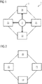
- FIG.1 is a schematic diagram of an exemplary multi-terminal HVDC network system 1 comprising several converter stations 2 and a DC grid master controller 3. Each converter station 20, 21, 22, 23 is communicating with a central DC grid master controller 3. The voltages of the converter stations 2 are managed and coordinated by this central controller 3.
- FIG.2 is a schematic diagram showing a multi-terminal HVDC network system 1 comprising several converter stations 2 when the DC grid master controller 3 is not in communication with the converter stations 2. This may happen during any emergency situation. However, even during such an emergency condition the system voltage is maintained within stable limits using the method 100 described here in order to guarantee for an uninterrupted, continuous operation.
- the disclosed method 100 provides for a communication-free, reliable handling of over-voltages and under-voltages in the system 1, managed independently by the individual converter stations 2.
- the converter stations 2 activate the power set value modification process on detecting an over-voltage or an under-voltage condition. Hence, the actual regulation is implemented at the converter station level.
- FIG.3 shows a graph depicting an example of a staggered voltage profile with time 't' 30 on x-axis and voltage 'V' 31 in kV on y-axis.
- different curves 200, 210 are shown for two converter stations 20, 21 to facilitate understanding.
- Curve 200 represents voltage-time curve for converter station 20
- curve 210 represents voltage-time curve for converter station 21. It can be seen that the curves 200, 210 of the two converter stations 20, 21 follow both slightly modified voltage levels, such as VOV.20 4 and VOV.21 5, as well as different permitted durations, TOV.20 6 and TOV.21 7.
- Vref 8 The voltage band for normal operation of the system is shown by Vband 9.
- the predefined upper threshold voltage 10 and the predefined lower threshold voltage 11 form the upper and the lower limits of the Vband 9.
- FIG.4 is a flowchart depicting the method 100 for regulating voltage in a multi-terminal HVDC network system 1 comprising at least one participating converter station 2.
- the flowchart displays the actions that are carried out in every time step and at every converter station participating in the proposed method 100.
- the method 100 comprises a first step 101 of measuring a local DC voltage at the participating converter station 20.
- the method further comprises a second step 102 of detecting an over-voltage condition when the measured DC voltage crosses a predefined upper threshold voltage 10 or detecting an under-voltage condition when the measured DC voltage crosses a predefined lower threshold voltage 11.
- a step 103 of triggering modification of an available DC power set value is executed by the said converter station 20.
- the step 103 of triggering modification envisages modification of the DC power set value by changing it according to a previously defined rate of speed (in Mega Watts per second) and temporal distance to the detection of the extraordinary condition, at time instant t0.
- the method finally comprises a step 104 of checking for termination of the modification step 103 when the over-voltage condition or the under-voltage condition no longer persists.
Landscapes
- Engineering & Computer Science (AREA)
- Power Engineering (AREA)
- Remote Monitoring And Control Of Power-Distribution Networks (AREA)
- Inverter Devices (AREA)
- Supply And Distribution Of Alternating Current (AREA)
Claims (2)
- Procédé (100) pour réguler une tension dans un système (1) de réseau HVDC, ou réseau continu à haute tension à bornes multiples, comportant au moins un poste (2) onduleur participant,
le procédé (100) comportant :- une étape (101) de mesure d'une tension à courant continu locale au poste (20) onduleur participant ;- une étape (102) de détection d'un état de surtension lorsque la tension à courant continu locale traverse une tension de seuil supérieure définie à l'avance ou une étape de détection d'un état de sous-tension lorsque la tension à courant continu locale traverse une tension de seuil inférieure définie à l'avance ;- une étape (103) de déclenchement de modification d'une valeur réglée de puissance à courant continu disponible au poste (10) onduleur à la détection de l'état de surtension ou de l'état de sous-tension, dans lequel la valeur réglée de puissance à courant continu est modifiée de manière autonome, c'est-à-dire sans consulter un dispositif de commande maître de grille à courant continu central, sur la base d'une rampe de puissance définie de pente définie ; dans lequel la modification de la valeur de réglage de puissance est effectuée en utilisant des valeurs de réglage de puissance et des durées de modification précédentes, c'est-à-dire conformément à un taux de vitesse (en mégawatts par seconde) et à une distance temporelle jusqu'à la détection définis précédemment ;- une étape (104) de vérification de la terminaison de l'étape (103) de modification lorsque la condition de surtension ou la condition de sous-tension ne persiste plus. - Procédé (100) suivant la revendication 1, dans lequel la modification de la valeur de réglage de puissance à courant continu est précisée par un paramètre constant et défini à l'avance.
Priority Applications (1)
| Application Number | Priority Date | Filing Date | Title |
|---|---|---|---|
| PL14714614T PL3100331T3 (pl) | 2014-03-18 | 2014-03-18 | Regulacja napięcia w wieloterminalowej sieci HVDC |
Applications Claiming Priority (1)
| Application Number | Priority Date | Filing Date | Title |
|---|---|---|---|
| PCT/EP2014/055412 WO2015139738A1 (fr) | 2014-03-18 | 2014-03-18 | Régulation de tension dans un réseau htcc à terminaux multiples |
Publications (2)
| Publication Number | Publication Date |
|---|---|
| EP3100331A1 EP3100331A1 (fr) | 2016-12-07 |
| EP3100331B1 true EP3100331B1 (fr) | 2019-05-01 |
Family
ID=50424196
Family Applications (1)
| Application Number | Title | Priority Date | Filing Date |
|---|---|---|---|
| EP14714614.6A Active EP3100331B1 (fr) | 2014-03-18 | 2014-03-18 | Procédé de réglage de tension dans un réseau de courant continu à haute tension (hvdc) |
Country Status (4)
| Country | Link |
|---|---|
| EP (1) | EP3100331B1 (fr) |
| ES (1) | ES2739680T3 (fr) |
| PL (1) | PL3100331T3 (fr) |
| WO (1) | WO2015139738A1 (fr) |
Families Citing this family (2)
| Publication number | Priority date | Publication date | Assignee | Title |
|---|---|---|---|---|
| CN110350505B (zh) * | 2019-07-15 | 2020-10-27 | 贵州电网有限责任公司 | 一种抑制柔直输电功率调整时直流电压波动的控制方法 |
| FR3099858B1 (fr) * | 2019-08-05 | 2021-09-17 | Inst Supergrid | Procédé de supervision d’une installation HVDC |
Family Cites Families (4)
| Publication number | Priority date | Publication date | Assignee | Title |
|---|---|---|---|---|
| WO2012000548A1 (fr) * | 2010-06-30 | 2012-01-05 | Abb Technology Ag | Système de transmission continu multi-borne et procédé et moyens de commande de ce système |
| CN103119821B (zh) | 2010-09-30 | 2016-01-13 | Abb研究有限公司 | 多端hvdc系统的协调控制 |
| EP2495864B1 (fr) * | 2011-03-02 | 2018-08-08 | GE Energy Power Conversion Technology Limited | Agencement de contrôle et procédé de régulation du courant de sortie d'un convertisseur de puissance de source cc connecté à un système cc multi-source |
| GB2501057B (en) * | 2012-03-05 | 2014-09-17 | Alstom Technology Ltd | Method of fault clearance |
-
2014
- 2014-03-18 EP EP14714614.6A patent/EP3100331B1/fr active Active
- 2014-03-18 PL PL14714614T patent/PL3100331T3/pl unknown
- 2014-03-18 ES ES14714614T patent/ES2739680T3/es active Active
- 2014-03-18 WO PCT/EP2014/055412 patent/WO2015139738A1/fr active Application Filing
Non-Patent Citations (1)
| Title |
|---|
| None * |
Also Published As
| Publication number | Publication date |
|---|---|
| ES2739680T3 (es) | 2020-02-03 |
| EP3100331A1 (fr) | 2016-12-07 |
| PL3100331T3 (pl) | 2019-10-31 |
| WO2015139738A1 (fr) | 2015-09-24 |
Similar Documents
| Publication | Publication Date | Title |
|---|---|---|
| EP3618217B1 (fr) | Centrale photovoltaïque et son procédé de réglage secondaire | |
| EP3054573B1 (fr) | Procédés et systèmes permettant d'améliorer la réponse transitoire de charge dans des systèmes de conversion d'énergie | |
| EP3051653B1 (fr) | Procédé et appareil de régulation de tension en courant continu | |
| EP2940824A1 (fr) | Améliorations apportées à, ou relatives à, des convertisseurs de source de tension | |
| Barker et al. | Further developments in autonomous converter control in a multi-terminal HVDC system | |
| EP3100331B1 (fr) | Procédé de réglage de tension dans un réseau de courant continu à haute tension (hvdc) | |
| US9825523B2 (en) | Control arrangement and method for regulating the output current of a dc source power converter connected to a multi-source dc system | |
| JP2014217195A (ja) | 料金設定装置、電力調整装置 | |
| EP4318844A1 (fr) | Système d'alimentation électrique et procédé de détection de topologie | |
| JP2019201453A (ja) | 電力供給システムおよび電力管理方法 | |
| WO2016189756A1 (fr) | Dispositif de commande de génération d'énergie électrique, dispositif de commande, procédé de commande et support d'enregistrement | |
| JP6952245B2 (ja) | 電力変換システム | |
| CN110224425B (zh) | 混合直流输电系统的控制方法 | |
| EP3711134B1 (fr) | Procédé basé sur un relâchement de tension dans un système de transmission d'énergie | |
| RU127537U1 (ru) | Устройство для автоматического ограничения перегрузки кабельно-воздушной линии электропередачи | |
| JP5205654B2 (ja) | 分散直流電源制御回路 | |
| KR20180131311A (ko) | 분산전원용 pcs를 보호하기 위한 전원 감시 시스템 및 그 방법 | |
| CN210464725U (zh) | 一种监测电缆温度的系统 | |
| JP6787473B1 (ja) | 分散型電源システム | |
| CN117318309B (zh) | 储能电源远程监测与操控系统、方法以及可读存储介质 | |
| US11942790B2 (en) | HVDC power transmission | |
| JP6791343B1 (ja) | 分散型電源システム | |
| US10073485B2 (en) | Method for compensating instantaneous power failure in medium voltage inverter and medium voltage inverter system using the same | |
| EP3806262A1 (fr) | Dispositif de commande et dispositif de conversion de puissance | |
| CN114362192A (zh) | 一种功率耗散装置及其控制方法和装置 |
Legal Events
| Date | Code | Title | Description |
|---|---|---|---|
| PUAI | Public reference made under article 153(3) epc to a published international application that has entered the european phase |
Free format text: ORIGINAL CODE: 0009012 |
|
| STAA | Information on the status of an ep patent application or granted ep patent |
Free format text: STATUS: REQUEST FOR EXAMINATION WAS MADE |
|
| 17P | Request for examination filed |
Effective date: 20160822 |
|
| AK | Designated contracting states |
Kind code of ref document: A1 Designated state(s): AL AT BE BG CH CY CZ DE DK EE ES FI FR GB GR HR HU IE IS IT LI LT LU LV MC MK MT NL NO PL PT RO RS SE SI SK SM TR |
|
| AX | Request for extension of the european patent |
Extension state: BA ME |
|
| DAX | Request for extension of the european patent (deleted) | ||
| RAP1 | Party data changed (applicant data changed or rights of an application transferred) |
Owner name: SIEMENS AKTIENGESELLSCHAFT |
|
| STAA | Information on the status of an ep patent application or granted ep patent |
Free format text: STATUS: EXAMINATION IS IN PROGRESS |
|
| 17Q | First examination report despatched |
Effective date: 20180606 |
|
| GRAP | Despatch of communication of intention to grant a patent |
Free format text: ORIGINAL CODE: EPIDOSNIGR1 |
|
| STAA | Information on the status of an ep patent application or granted ep patent |
Free format text: STATUS: GRANT OF PATENT IS INTENDED |
|
| INTG | Intention to grant announced |
Effective date: 20181029 |
|
| GRAS | Grant fee paid |
Free format text: ORIGINAL CODE: EPIDOSNIGR3 |
|
| GRAA | (expected) grant |
Free format text: ORIGINAL CODE: 0009210 |
|
| STAA | Information on the status of an ep patent application or granted ep patent |
Free format text: STATUS: THE PATENT HAS BEEN GRANTED |
|
| AK | Designated contracting states |
Kind code of ref document: B1 Designated state(s): AL AT BE BG CH CY CZ DE DK EE ES FI FR GB GR HR HU IE IS IT LI LT LU LV MC MK MT NL NO PL PT RO RS SE SI SK SM TR |
|
| REG | Reference to a national code |
Ref country code: GB Ref legal event code: FG4D |
|
| REG | Reference to a national code |
Ref country code: CH Ref legal event code: EP Ref country code: AT Ref legal event code: REF Ref document number: 1128198 Country of ref document: AT Kind code of ref document: T Effective date: 20190515 |
|
| REG | Reference to a national code |
Ref country code: DE Ref legal event code: R096 Ref document number: 602014045720 Country of ref document: DE |
|
| REG | Reference to a national code |
Ref country code: IE Ref legal event code: FG4D |
|
| REG | Reference to a national code |
Ref country code: NL Ref legal event code: MP Effective date: 20190501 |
|
| REG | Reference to a national code |
Ref country code: LT Ref legal event code: MG4D |
|
| PG25 | Lapsed in a contracting state [announced via postgrant information from national office to epo] |
Ref country code: FI Free format text: LAPSE BECAUSE OF FAILURE TO SUBMIT A TRANSLATION OF THE DESCRIPTION OR TO PAY THE FEE WITHIN THE PRESCRIBED TIME-LIMIT Effective date: 20190501 Ref country code: LT Free format text: LAPSE BECAUSE OF FAILURE TO SUBMIT A TRANSLATION OF THE DESCRIPTION OR TO PAY THE FEE WITHIN THE PRESCRIBED TIME-LIMIT Effective date: 20190501 Ref country code: SE Free format text: LAPSE BECAUSE OF FAILURE TO SUBMIT A TRANSLATION OF THE DESCRIPTION OR TO PAY THE FEE WITHIN THE PRESCRIBED TIME-LIMIT Effective date: 20190501 Ref country code: NL Free format text: LAPSE BECAUSE OF FAILURE TO SUBMIT A TRANSLATION OF THE DESCRIPTION OR TO PAY THE FEE WITHIN THE PRESCRIBED TIME-LIMIT Effective date: 20190501 Ref country code: PT Free format text: LAPSE BECAUSE OF FAILURE TO SUBMIT A TRANSLATION OF THE DESCRIPTION OR TO PAY THE FEE WITHIN THE PRESCRIBED TIME-LIMIT Effective date: 20190901 Ref country code: AL Free format text: LAPSE BECAUSE OF FAILURE TO SUBMIT A TRANSLATION OF THE DESCRIPTION OR TO PAY THE FEE WITHIN THE PRESCRIBED TIME-LIMIT Effective date: 20190501 Ref country code: NO Free format text: LAPSE BECAUSE OF FAILURE TO SUBMIT A TRANSLATION OF THE DESCRIPTION OR TO PAY THE FEE WITHIN THE PRESCRIBED TIME-LIMIT Effective date: 20190801 Ref country code: HR Free format text: LAPSE BECAUSE OF FAILURE TO SUBMIT A TRANSLATION OF THE DESCRIPTION OR TO PAY THE FEE WITHIN THE PRESCRIBED TIME-LIMIT Effective date: 20190501 |
|
| PG25 | Lapsed in a contracting state [announced via postgrant information from national office to epo] |
Ref country code: LV Free format text: LAPSE BECAUSE OF FAILURE TO SUBMIT A TRANSLATION OF THE DESCRIPTION OR TO PAY THE FEE WITHIN THE PRESCRIBED TIME-LIMIT Effective date: 20190501 Ref country code: BG Free format text: LAPSE BECAUSE OF FAILURE TO SUBMIT A TRANSLATION OF THE DESCRIPTION OR TO PAY THE FEE WITHIN THE PRESCRIBED TIME-LIMIT Effective date: 20190801 Ref country code: GR Free format text: LAPSE BECAUSE OF FAILURE TO SUBMIT A TRANSLATION OF THE DESCRIPTION OR TO PAY THE FEE WITHIN THE PRESCRIBED TIME-LIMIT Effective date: 20190802 Ref country code: RS Free format text: LAPSE BECAUSE OF FAILURE TO SUBMIT A TRANSLATION OF THE DESCRIPTION OR TO PAY THE FEE WITHIN THE PRESCRIBED TIME-LIMIT Effective date: 20190501 |
|
| REG | Reference to a national code |
Ref country code: AT Ref legal event code: MK05 Ref document number: 1128198 Country of ref document: AT Kind code of ref document: T Effective date: 20190501 |
|
| PG25 | Lapsed in a contracting state [announced via postgrant information from national office to epo] |
Ref country code: IS Free format text: LAPSE BECAUSE OF FAILURE TO SUBMIT A TRANSLATION OF THE DESCRIPTION OR TO PAY THE FEE WITHIN THE PRESCRIBED TIME-LIMIT Effective date: 20190901 |
|
| PG25 | Lapsed in a contracting state [announced via postgrant information from national office to epo] |
Ref country code: CZ Free format text: LAPSE BECAUSE OF FAILURE TO SUBMIT A TRANSLATION OF THE DESCRIPTION OR TO PAY THE FEE WITHIN THE PRESCRIBED TIME-LIMIT Effective date: 20190501 Ref country code: RO Free format text: LAPSE BECAUSE OF FAILURE TO SUBMIT A TRANSLATION OF THE DESCRIPTION OR TO PAY THE FEE WITHIN THE PRESCRIBED TIME-LIMIT Effective date: 20190501 Ref country code: EE Free format text: LAPSE BECAUSE OF FAILURE TO SUBMIT A TRANSLATION OF THE DESCRIPTION OR TO PAY THE FEE WITHIN THE PRESCRIBED TIME-LIMIT Effective date: 20190501 Ref country code: AT Free format text: LAPSE BECAUSE OF FAILURE TO SUBMIT A TRANSLATION OF THE DESCRIPTION OR TO PAY THE FEE WITHIN THE PRESCRIBED TIME-LIMIT Effective date: 20190501 Ref country code: DK Free format text: LAPSE BECAUSE OF FAILURE TO SUBMIT A TRANSLATION OF THE DESCRIPTION OR TO PAY THE FEE WITHIN THE PRESCRIBED TIME-LIMIT Effective date: 20190501 Ref country code: SK Free format text: LAPSE BECAUSE OF FAILURE TO SUBMIT A TRANSLATION OF THE DESCRIPTION OR TO PAY THE FEE WITHIN THE PRESCRIBED TIME-LIMIT Effective date: 20190501 |
|
| REG | Reference to a national code |
Ref country code: ES Ref legal event code: FG2A Ref document number: 2739680 Country of ref document: ES Kind code of ref document: T3 Effective date: 20200203 |
|
| REG | Reference to a national code |
Ref country code: DE Ref legal event code: R097 Ref document number: 602014045720 Country of ref document: DE |
|
| PG25 | Lapsed in a contracting state [announced via postgrant information from national office to epo] |
Ref country code: SM Free format text: LAPSE BECAUSE OF FAILURE TO SUBMIT A TRANSLATION OF THE DESCRIPTION OR TO PAY THE FEE WITHIN THE PRESCRIBED TIME-LIMIT Effective date: 20190501 |
|
| PLBE | No opposition filed within time limit |
Free format text: ORIGINAL CODE: 0009261 |
|
| STAA | Information on the status of an ep patent application or granted ep patent |
Free format text: STATUS: NO OPPOSITION FILED WITHIN TIME LIMIT |
|
| PG25 | Lapsed in a contracting state [announced via postgrant information from national office to epo] |
Ref country code: TR Free format text: LAPSE BECAUSE OF FAILURE TO SUBMIT A TRANSLATION OF THE DESCRIPTION OR TO PAY THE FEE WITHIN THE PRESCRIBED TIME-LIMIT Effective date: 20190501 |
|
| 26N | No opposition filed |
Effective date: 20200204 |
|
| PG25 | Lapsed in a contracting state [announced via postgrant information from national office to epo] |
Ref country code: SI Free format text: LAPSE BECAUSE OF FAILURE TO SUBMIT A TRANSLATION OF THE DESCRIPTION OR TO PAY THE FEE WITHIN THE PRESCRIBED TIME-LIMIT Effective date: 20190501 |
|
| PG25 | Lapsed in a contracting state [announced via postgrant information from national office to epo] |
Ref country code: MC Free format text: LAPSE BECAUSE OF FAILURE TO SUBMIT A TRANSLATION OF THE DESCRIPTION OR TO PAY THE FEE WITHIN THE PRESCRIBED TIME-LIMIT Effective date: 20190501 |
|
| REG | Reference to a national code |
Ref country code: CH Ref legal event code: PL |
|
| REG | Reference to a national code |
Ref country code: DE Ref legal event code: R081 Ref document number: 602014045720 Country of ref document: DE Owner name: SIEMENS ENERGY GLOBAL GMBH & CO. KG, DE Free format text: FORMER OWNER: SIEMENS AKTIENGESELLSCHAFT, 80333 MUENCHEN, DE |
|
| REG | Reference to a national code |
Ref country code: BE Ref legal event code: MM Effective date: 20200331 |
|
| PG25 | Lapsed in a contracting state [announced via postgrant information from national office to epo] |
Ref country code: LU Free format text: LAPSE BECAUSE OF NON-PAYMENT OF DUE FEES Effective date: 20200318 |
|
| PG25 | Lapsed in a contracting state [announced via postgrant information from national office to epo] |
Ref country code: LI Free format text: LAPSE BECAUSE OF NON-PAYMENT OF DUE FEES Effective date: 20200331 Ref country code: IE Free format text: LAPSE BECAUSE OF NON-PAYMENT OF DUE FEES Effective date: 20200318 Ref country code: CH Free format text: LAPSE BECAUSE OF NON-PAYMENT OF DUE FEES Effective date: 20200331 |
|
| PG25 | Lapsed in a contracting state [announced via postgrant information from national office to epo] |
Ref country code: BE Free format text: LAPSE BECAUSE OF NON-PAYMENT OF DUE FEES Effective date: 20200331 |
|
| PG25 | Lapsed in a contracting state [announced via postgrant information from national office to epo] |
Ref country code: MT Free format text: LAPSE BECAUSE OF FAILURE TO SUBMIT A TRANSLATION OF THE DESCRIPTION OR TO PAY THE FEE WITHIN THE PRESCRIBED TIME-LIMIT Effective date: 20190501 Ref country code: CY Free format text: LAPSE BECAUSE OF FAILURE TO SUBMIT A TRANSLATION OF THE DESCRIPTION OR TO PAY THE FEE WITHIN THE PRESCRIBED TIME-LIMIT Effective date: 20190501 |
|
| PG25 | Lapsed in a contracting state [announced via postgrant information from national office to epo] |
Ref country code: MK Free format text: LAPSE BECAUSE OF FAILURE TO SUBMIT A TRANSLATION OF THE DESCRIPTION OR TO PAY THE FEE WITHIN THE PRESCRIBED TIME-LIMIT Effective date: 20190501 |
|
| REG | Reference to a national code |
Ref country code: GB Ref legal event code: 732E Free format text: REGISTERED BETWEEN 20220901 AND 20220907 |
|
| PGFP | Annual fee paid to national office [announced via postgrant information from national office to epo] |
Ref country code: FR Payment date: 20230323 Year of fee payment: 10 |
|
| PGFP | Annual fee paid to national office [announced via postgrant information from national office to epo] |
Ref country code: PL Payment date: 20230310 Year of fee payment: 10 Ref country code: IT Payment date: 20230321 Year of fee payment: 10 |
|
| PGFP | Annual fee paid to national office [announced via postgrant information from national office to epo] |
Ref country code: ES Payment date: 20230424 Year of fee payment: 10 |
|
| REG | Reference to a national code |
Ref country code: ES Ref legal event code: PC2A Owner name: SIEMENS ENERGY GLOBAL GMBH & CO. KG Effective date: 20240403 |
|
| PGFP | Annual fee paid to national office [announced via postgrant information from national office to epo] |
Ref country code: DE Payment date: 20240328 Year of fee payment: 11 Ref country code: GB Payment date: 20240319 Year of fee payment: 11 |