EP2940824A1 - Améliorations apportées à, ou relatives à, des convertisseurs de source de tension - Google Patents
Améliorations apportées à, ou relatives à, des convertisseurs de source de tension Download PDFInfo
- Publication number
- EP2940824A1 EP2940824A1 EP14275095.9A EP14275095A EP2940824A1 EP 2940824 A1 EP2940824 A1 EP 2940824A1 EP 14275095 A EP14275095 A EP 14275095A EP 2940824 A1 EP2940824 A1 EP 2940824A1
- Authority
- EP
- European Patent Office
- Prior art keywords
- voltage source
- source converter
- wind farm
- side voltage
- terminal
- Prior art date
- Legal status (The legal status is an assumption and is not a legal conclusion. Google has not performed a legal analysis and makes no representation as to the accuracy of the status listed.)
- Granted
Links
- 230000005540 biological transmission Effects 0.000 claims abstract description 64
- 230000004044 response Effects 0.000 claims abstract description 12
- 230000001419 dependent effect Effects 0.000 claims 3
- 230000008878 coupling Effects 0.000 description 15
- 238000010168 coupling process Methods 0.000 description 15
- 238000005859 coupling reaction Methods 0.000 description 15
- 230000008859 change Effects 0.000 description 5
- 238000012546 transfer Methods 0.000 description 5
- 239000003990 capacitor Substances 0.000 description 4
- 230000000694 effects Effects 0.000 description 4
- 238000006243 chemical reaction Methods 0.000 description 3
- 239000004065 semiconductor Substances 0.000 description 2
- 238000000926 separation method Methods 0.000 description 2
- 230000004075 alteration Effects 0.000 description 1
- 238000013459 approach Methods 0.000 description 1
- 238000004891 communication Methods 0.000 description 1
- 238000004146 energy storage Methods 0.000 description 1
- 238000003780 insertion Methods 0.000 description 1
- 230000037431 insertion Effects 0.000 description 1
- 230000004048 modification Effects 0.000 description 1
- 238000012986 modification Methods 0.000 description 1
- 230000009467 reduction Effects 0.000 description 1
Images


Classifications
-
- H—ELECTRICITY
- H02—GENERATION; CONVERSION OR DISTRIBUTION OF ELECTRIC POWER
- H02J—CIRCUIT ARRANGEMENTS OR SYSTEMS FOR SUPPLYING OR DISTRIBUTING ELECTRIC POWER; SYSTEMS FOR STORING ELECTRIC ENERGY
- H02J3/00—Circuit arrangements for ac mains or ac distribution networks
- H02J3/38—Arrangements for parallely feeding a single network by two or more generators, converters or transformers
- H02J3/381—Dispersed generators
-
- H—ELECTRICITY
- H02—GENERATION; CONVERSION OR DISTRIBUTION OF ELECTRIC POWER
- H02J—CIRCUIT ARRANGEMENTS OR SYSTEMS FOR SUPPLYING OR DISTRIBUTING ELECTRIC POWER; SYSTEMS FOR STORING ELECTRIC ENERGY
- H02J5/00—Circuit arrangements for transfer of electric power between ac networks and dc networks
-
- H—ELECTRICITY
- H02—GENERATION; CONVERSION OR DISTRIBUTION OF ELECTRIC POWER
- H02M—APPARATUS FOR CONVERSION BETWEEN AC AND AC, BETWEEN AC AND DC, OR BETWEEN DC AND DC, AND FOR USE WITH MAINS OR SIMILAR POWER SUPPLY SYSTEMS; CONVERSION OF DC OR AC INPUT POWER INTO SURGE OUTPUT POWER; CONTROL OR REGULATION THEREOF
- H02M5/00—Conversion of ac power input into ac power output, e.g. for change of voltage, for change of frequency, for change of number of phases
- H02M5/40—Conversion of ac power input into ac power output, e.g. for change of voltage, for change of frequency, for change of number of phases with intermediate conversion into dc
-
- H—ELECTRICITY
- H02—GENERATION; CONVERSION OR DISTRIBUTION OF ELECTRIC POWER
- H02M—APPARATUS FOR CONVERSION BETWEEN AC AND AC, BETWEEN AC AND DC, OR BETWEEN DC AND DC, AND FOR USE WITH MAINS OR SIMILAR POWER SUPPLY SYSTEMS; CONVERSION OF DC OR AC INPUT POWER INTO SURGE OUTPUT POWER; CONTROL OR REGULATION THEREOF
- H02M7/00—Conversion of ac power input into dc power output; Conversion of dc power input into ac power output
- H02M7/02—Conversion of ac power input into dc power output without possibility of reversal
-
- H—ELECTRICITY
- H02—GENERATION; CONVERSION OR DISTRIBUTION OF ELECTRIC POWER
- H02P—CONTROL OR REGULATION OF ELECTRIC MOTORS, ELECTRIC GENERATORS OR DYNAMO-ELECTRIC CONVERTERS; CONTROLLING TRANSFORMERS, REACTORS OR CHOKE COILS
- H02P9/00—Arrangements for controlling electric generators for the purpose of obtaining a desired output
- H02P9/10—Control effected upon generator excitation circuit to reduce harmful effects of overloads or transients, e.g. sudden application of load, sudden removal of load, sudden change of load
- H02P9/102—Control effected upon generator excitation circuit to reduce harmful effects of overloads or transients, e.g. sudden application of load, sudden removal of load, sudden change of load for limiting effects of transients
-
- H—ELECTRICITY
- H02—GENERATION; CONVERSION OR DISTRIBUTION OF ELECTRIC POWER
- H02J—CIRCUIT ARRANGEMENTS OR SYSTEMS FOR SUPPLYING OR DISTRIBUTING ELECTRIC POWER; SYSTEMS FOR STORING ELECTRIC ENERGY
- H02J3/00—Circuit arrangements for ac mains or ac distribution networks
- H02J3/36—Arrangements for transfer of electric power between ac networks via a high-tension dc link
- H02J2003/365—Reducing harmonics or oscillations in HVDC
-
- H—ELECTRICITY
- H02—GENERATION; CONVERSION OR DISTRIBUTION OF ELECTRIC POWER
- H02J—CIRCUIT ARRANGEMENTS OR SYSTEMS FOR SUPPLYING OR DISTRIBUTING ELECTRIC POWER; SYSTEMS FOR STORING ELECTRIC ENERGY
- H02J2300/00—Systems for supplying or distributing electric power characterised by decentralized, dispersed, or local generation
- H02J2300/20—The dispersed energy generation being of renewable origin
- H02J2300/28—The renewable source being wind energy
-
- H—ELECTRICITY
- H02—GENERATION; CONVERSION OR DISTRIBUTION OF ELECTRIC POWER
- H02J—CIRCUIT ARRANGEMENTS OR SYSTEMS FOR SUPPLYING OR DISTRIBUTING ELECTRIC POWER; SYSTEMS FOR STORING ELECTRIC ENERGY
- H02J3/00—Circuit arrangements for ac mains or ac distribution networks
- H02J3/38—Arrangements for parallely feeding a single network by two or more generators, converters or transformers
- H02J3/388—Islanding, i.e. disconnection of local power supply from the network
-
- H—ELECTRICITY
- H02—GENERATION; CONVERSION OR DISTRIBUTION OF ELECTRIC POWER
- H02P—CONTROL OR REGULATION OF ELECTRIC MOTORS, ELECTRIC GENERATORS OR DYNAMO-ELECTRIC CONVERTERS; CONTROLLING TRANSFORMERS, REACTORS OR CHOKE COILS
- H02P2101/00—Special adaptation of control arrangements for generators
- H02P2101/15—Special adaptation of control arrangements for generators for wind-driven turbines
-
- H—ELECTRICITY
- H02—GENERATION; CONVERSION OR DISTRIBUTION OF ELECTRIC POWER
- H02P—CONTROL OR REGULATION OF ELECTRIC MOTORS, ELECTRIC GENERATORS OR DYNAMO-ELECTRIC CONVERTERS; CONTROLLING TRANSFORMERS, REACTORS OR CHOKE COILS
- H02P2201/00—Indexing scheme relating to controlling arrangements characterised by the converter used
- H02P2201/01—AC-AC converter stage controlled to provide a defined AC voltage
-
- H—ELECTRICITY
- H02—GENERATION; CONVERSION OR DISTRIBUTION OF ELECTRIC POWER
- H02P—CONTROL OR REGULATION OF ELECTRIC MOTORS, ELECTRIC GENERATORS OR DYNAMO-ELECTRIC CONVERTERS; CONTROLLING TRANSFORMERS, REACTORS OR CHOKE COILS
- H02P2201/00—Indexing scheme relating to controlling arrangements characterised by the converter used
- H02P2201/03—AC-DC converter stage controlled to provide a defined DC link voltage
-
- Y—GENERAL TAGGING OF NEW TECHNOLOGICAL DEVELOPMENTS; GENERAL TAGGING OF CROSS-SECTIONAL TECHNOLOGIES SPANNING OVER SEVERAL SECTIONS OF THE IPC; TECHNICAL SUBJECTS COVERED BY FORMER USPC CROSS-REFERENCE ART COLLECTIONS [XRACs] AND DIGESTS
- Y02—TECHNOLOGIES OR APPLICATIONS FOR MITIGATION OR ADAPTATION AGAINST CLIMATE CHANGE
- Y02E—REDUCTION OF GREENHOUSE GAS [GHG] EMISSIONS, RELATED TO ENERGY GENERATION, TRANSMISSION OR DISTRIBUTION
- Y02E10/00—Energy generation through renewable energy sources
- Y02E10/70—Wind energy
- Y02E10/76—Power conversion electric or electronic aspects
Definitions
- Modifying the active power demand of the voltage source converter by introducing an artificial inertia factor compensates for a lack of mechanical resistance in the or each wind turbine of the wind farm. This, in turn, helps to resolve instability issues in a main AC grid where the power output of the wind farm is evacuated which might otherwise be caused by operation of the voltage source converter. It also helps to smooth out variations in the frequency at which the voltage source operator operates.
- Such a configuration can be readily implemented by minor alteration of the operating algorithms of the power-frequency slope sub-controller.
- a lagging function desirably effects the rate at which the frequency value output by the power-frequency slope sub-controller varies.
- main controller configured in the foregoing manner allows the main controller to vary the active power output by the wind farm side voltage source converter so that it is aligned with the active power demand of, e.g. a grid side voltage source converter which in use is connected with the wind farm side voltage source converter by a DC transmission link, such that, e.g. the grid side voltage source converter is able to act as a master converter while the wind farm side converter acts as a slave converter.
- the altered active power demand may be passed through the power-frequency slope sub-controller before an artificial inertia factor is applied to the resulting frequency.
- Such an arrangement allows for the implementation of a master-slave control relationship between the wind farm side voltage source converter and, e.g. a grid side voltage source converter, in a manner whereby the wind farm side voltage source converter remains stable and subject only to smooth variations in operating frequency.
- the frequency at which the grid side voltage source converter operates will, in use, have a tendency to increase in the event of a fault in the main AC grid which gives rise to an islanding of the second electrical system, i.e. a separation of the second electrical system from the main AC grid, e.g. by the tripping of a remote breaker elsewhere in the main AC grid.
- the first main controller 10 is shown schematically in Figure 1 and is configured to modify an active power demand P demand of the first wind farm side voltage source converter of which the first main controller 10 forms a part.
- the active power demand P demand i.e. the active power that the first wind farm side voltage source converter is required to provide, is provided by a higher level controller (not shown) such as, for example, a dispatch centre.
- the first main controller 10 is configured to modify the active power demand P demand by introducing an artificial inertia factor.
- the first main controller 10 includes a power-frequency slope sub-controller 12 and is configured to pass the active power demand P demand through the power-frequency slope sub-controller 12 in order to transform the associated active power value into a frequency value.
- the first main controller 10 subtracts the active power demand P demand from an active power value P msr measured at a point of common coupling between the first wind farm side voltage source converter and the wind farm to which it is in use connected.
- the power-frequency slope sub-controller 12 applies the artificial inertia factor, which takes the form of a lagging function.
- the lagging function is defined by: 1 1 + sT
- This frequency demand f demand i.e. the frequency at which the first wind farm side voltage source converter is required to operate, is provided by the same higher level controller as that which provides the active power demand P demand .
- the first main controller 10 acts as a frequency controller with the control loop embodied therein being altered by a power demand error, i.e. the difference between the active power demand P demand and the measured active power P msr .
- a wind farm side voltage source converter is similar to the first wind farm side voltage converter described above and like features share the same reference numerals.
- the second wind farm side voltage source converter also includes a DC terminal, which in use is connected to a DC transmission link, and an AC terminal which in use is connected to a wind farm.
- the second main controller 20 is configured to additionally modify the active power demand P demand in response to a measured DC voltage V dc_msr at the DC terminal of the second wind farm side voltage source converter, i.e. as shown in Figure 2 .
- the second main controller 20 carries out such modification by comparing the measured DC voltage V dc_msr with an expected DC voltage and altering the active power demand P demand when the measured DC voltage V dc_msr differs from the expected DC voltage to thereby produce a modified active power demand P demand_mod .
- the expected DC voltage is based on a DC voltage demand which is provided by the same higher level control that provides the active power demand P demand for the second wind farm side voltage source converter.
- the DC voltage demand may also be known as a Load Reference Set Point (LRSP) which is a target DC voltage that all gird side voltage source converters connected to a main grid are aimed to operate at.
- LRSP Load Reference Set Point
- the voltage level of a DC transmission link which in use connects the second wind farm side voltage source converter with a grid side voltage source converter that is the subject of the DC voltage demand V LRSP provided by the higher level controller, will also differ from the DC voltage demand V LRSP .
- the voltage level of the DC transmission link manifests itself as a measured DC voltage V dc_msr at the second wind farm side voltage source converter, and so any difference between the voltage level of the DC transmission link and the DC voltage demand V LRSP is detectable by the second main controller 20 of the second wind farm side voltage source converter.
- the second main controller 20 sums the DC voltage demand V LRSP and the voltage drop ⁇ V along the DC transmission link and then subtracts this from the measured DC voltage V dc_msr at the DC terminal of the second wind farm side voltage source converter.
- the output of this manipulation is then preferably amplified by multiplying it by a gain factor 22 before being summed with the active power demand P demand received from the higher level controller to give the desired modified active power demand P demand_mod value.
- the second main controller subtracts the modified active power demand P demand_mod from an active power value P msr measured at the point of common coupling between the second wind farm side voltage source converter and the wind farm to which it is in use connected, and then applies an artificial inertia factor in the form of a lagging function as the altered modified active power demand P demand_mod passes through a power-frequency slope sub-controller 12.
- the frequency value resulting from the power-frequency slope sub-controller 12 is again then added to a frequency demand f demand provided by the higher level controller, and the sum of the frequency resulting from the power-frequency slope sub-controller 12 and the frequency demand f demand is passed through a frequency limiter 14 before being output as a frequency order f order which controls the frequency at which the second wind farm side voltage source converter is intended to operate.
- the second main controller 20 is therefore able to detect changes in the voltage level of a DC transmission link to which it is connected and thereafter automatically modify the active power demand P demand it receives from a higher level controller so that it can become aligned with, e.g. the active power P demand_grid_side demanded of a grid side voltage source converter connected to the other end of the DC transmission link.
- the second wind farm side voltage source converter desirably forms a part of a first electrical system 30 within which it is identified by reference numeral 32.
- the first electrical system 30 may itself form a part of a power transmission network 34 that includes a plurality of the first electrical systems 30 connected in parallel with one another, as shown in Figure 3 .
- Each of the first electrical systems 30 and the power transmission network 34 is an embodiment of the invention.
- Each first electrical system 30 includes a said second wind farm side voltage source converter 32 which has a first end 36 of a DC transmission link 38 connected to the DC terminal 40 thereof.
- Each second wind farm side voltage source converter 32 also includes an AC terminal 42 which is, in use, connected to a corresponding wind farm 44 that includes at least one wind turbine 46.
- the second wind farm side voltage source converter 32 may be connected to the wind farm 44 via a first point of common coupling 48 and a first transformer 50.
- a first circuit breaker 52 may also lie between the first point of common coupling 48 and the first transformer 50, although this need not necessarily be the case.
- the first grid side voltage source converter 54 in one of the first electrical systems 30 may be connected with the main AC grid 62 via a first overhead line 64 which extends from a second point of common coupling 66.
- a second transformer 68 and a second circuit breaker 70 may lie between the second point of common coupling 66 and the first grid side voltage source converter 54.
- Further remote circuit breakers 72 may lie towards either end of the first transmission line 64.
- each second wind farm side voltage source converter 32 includes a second main controller 20 which is configured to compare the measured DC voltage V dc_msr at the DC terminal 40 of the corresponding second wind farm side voltage source converter 32 with an expected DC voltage that is defined by the sum of a DC voltage demand V LRSP of the first grid side voltage source converter 54 (i.e. as received from a higher level controller) and the voltage drop ⁇ V along the DC transmission link 38.
- Each second main controller 20 is still further configured to alter the active power demand P demand of the corresponding second wind farm side voltage source converter 32 (i.e. as received from the higher level controller) when the measured DC voltage V dc_msr differs from the expected DC voltage.
- each first grid side voltage source converter 54 controls the flow of active power through the DC transmission link 38, rather than the corresponding second wind farm side voltage source converter 32 affecting such control.
- each first grid side voltage source converter 54 is considered to be a master converter, while each second wind farm side voltage source converter 32 acts as a slave converter.
- Adjacent wind farms 44 in the power transmission network 34 described above are connected to one another by a respective AC link 76 which may be an under-sea cable or an overhead line.
- each second main controller 20 may additionally include an AC voltage-reactive power droop sub-controller 78, as shown in Figure 4 , so that the AC voltage at which each second wind farm side voltage source converter 32 operates can be controlled jointly by the various second main controllers 20.
- each AC voltage-reactive power droop sub-controller 78 subtracts an AC reactive power demand Q demand (which it receives from a higher level controller) from a measured AC reactive power Q msr (which is taken at the corresponding first point of common coupling 48) and passes the result through a reactive power-voltage slope sub-controller 80 that converts the result into a voltage.
- a wind farm side voltage source converter according to a third embodiment of the invention is similar to each of the first and second wind farm side voltage source converters described hereinabove.
- the frequency value resulting from the power-frequency slope sub-controller is again then added to a frequency demand f demand provided by a higher level controller, and the sum of the frequency resulting from the power-frequency slope sub-controller 12 and the frequency demand f demand is passed through a frequency limiter 14 before being output as a frequency order f order which controls the frequency at which the third wind farm side voltage source converter is intended to operate.
- the third main controller produces the modified active power demand P demand_mod in a different way to the second main controller 20, as is illustrated schematically in Figure 5 .
- the third main controller is configured to compare a measured DC voltage V dc_msr , i.e. as measured at the DC terminal of the third wind farm side voltage source converter, with a predetermined DC over-voltage value which, in the embodiment shown, equates to a maximum acceptable limit V dc_max in terms of the operational safety of a grid side voltage source converter to which the third wind farm side voltage source converter is, in use, connected.
- the second electrical assembly 90 also includes a second grid side voltage source converter 92 which itself has a DC terminal 56 that is connected with a second end 58 of the DC transmission link 38, and also an AC terminal 60 which in use may be connected to a main AC grid 62.
- the AC terminal 60 of the second grid side voltage source converter 92 may be connected to the main AC grid 62 via a first overhead line 64 which extends from a second point of common coupling 66.
- a second transformer 68 and a second circuit breaker 70 may lie between the second point of common coupling 66 and the second grid side voltage source converter 92.
- Further remote circuit breakers 72 may lie towards either end of the first overhead line 64.
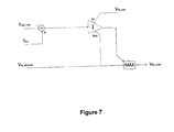
- the second grid side voltage source converter 92 includes a fourth main controller 98 which, as illustrated schematically in Figure 7 , is configured to detect an increase in the frequency at which the second grid side voltage source converter 92 is operating and thereafter increase the DC voltage at the DC terminal 56 of the second grid side voltage source converter 92 to a predetermined over-voltage value, i.e. a maximum acceptable limit V dc_max which continues to ensure the operational safety of the second grid side voltage source converter 92.
- a predetermined over-voltage value i.e. a maximum acceptable limit V dc_max which continues to ensure the operational safety of the second grid side voltage source converter 92.
- the fourth main controller 98 detects an increase in the frequency at which the second grid side voltage source converter 92 is operating by measuring the frequency f msr at the second point of common coupling 66 of the second grid side voltage source converter 92 and subtracting from this measured frequency f msr a maximum safe limit f max_limit of the frequency at the said second point of common coupling 66.
- the fourth main controller 98 changes the demanded DC voltage V dc_demand of the second grid side voltage source converter 92 (i.e. as received from a higher level controller) to a DC voltage level V dc_order at which the second grid side voltage source converter 92 is intended to operate that is equal to the predetermined over-voltage value, i.e. V dc_max in order to maintain the frequency of the second grid side voltage source converter 92 at the said maximum safe frequency f max_limit .
- Such an increase in the voltage level at the DC terminal 40 of the third wind farm side voltage source converter 94 is detected by the third main controller 96 of the third wind farm side voltage source converter 94, such that it is then able automatically to reduce the active power it transfers to the second grid side voltage source converter 92 through the associated DC transmission link 38.
- the frequency at the AC terminal 60 of the second grid side voltage source converter 92 will start to increase due to the separation of the third wind farm side voltage source converter 94 and its associated wind farm, together with the second grid side voltage source converter 92, from the main AC grid 62.
- the fourth main controller 98 of the second grid side voltage source converter 92 is able to maintain the frequency at an emergency level, i.e. at a maximum safe frequency f max_limit level, very close to the nominal operating frequency level (e.g. 52 Hz for a 50 Hz system) by increasing the DC voltage of the second grid side voltage source converter 92 to the predetermined over-voltage value, i.e. V dc_max (e.g. 1.1 pu).
- the third main controller 96 of the third wind farm side voltage source converter 94 automatically reduces the active power P demand demanded of it, and thereby reduces the active power it transfers to the second grid side voltage source converter 92, when it detects the increase in voltage at its DC terminal 40 that is occasioned by the aforementioned increase in the DC voltage of the second grid side voltage source converter 92.
- the second electrical system 90 results in a reduction, or even cessation, of the active power flowing through the DC transmission link 38 such that the operating frequency of second grid side voltage source converter 92 (which is now separated from the main AC grid 62, i.e. is now islanded from the main AC grid 62) is kept to the maximum safe limit f max_limit while at the same time the voltage level at the DC terminal 56 of the second grid side voltage source converter 92, and hence also the voltage level in the DC transmission link 38, does not exceed a maximum acceptable level, i.e. the predetermined over-voltage value V dc_max .
Priority Applications (4)
| Application Number | Priority Date | Filing Date | Title |
|---|---|---|---|
| EP14275095.9A EP2940824B1 (fr) | 2014-04-29 | 2014-04-29 | Améliorations apportées à, ou relatives à, des convertisseurs de source de tension |
| CN201580023520.7A CN106537759B (zh) | 2014-04-29 | 2015-04-28 | 电压源转换器的或与电压源转换器有关的改进 |
| PCT/EP2015/059146 WO2015165876A1 (fr) | 2014-04-29 | 2015-04-28 | Perfectionnements apportés ou se rapportant à des convertisseurs de source de tension |
| US15/307,566 US10305291B2 (en) | 2014-04-29 | 2015-04-28 | Voltage source convertors |
Applications Claiming Priority (1)
| Application Number | Priority Date | Filing Date | Title |
|---|---|---|---|
| EP14275095.9A EP2940824B1 (fr) | 2014-04-29 | 2014-04-29 | Améliorations apportées à, ou relatives à, des convertisseurs de source de tension |
Publications (2)
| Publication Number | Publication Date |
|---|---|
| EP2940824A1 true EP2940824A1 (fr) | 2015-11-04 |
| EP2940824B1 EP2940824B1 (fr) | 2022-11-23 |
Family
ID=50588605
Family Applications (1)
| Application Number | Title | Priority Date | Filing Date |
|---|---|---|---|
| EP14275095.9A Active EP2940824B1 (fr) | 2014-04-29 | 2014-04-29 | Améliorations apportées à, ou relatives à, des convertisseurs de source de tension |
Country Status (4)
| Country | Link |
|---|---|
| US (1) | US10305291B2 (fr) |
| EP (1) | EP2940824B1 (fr) |
| CN (1) | CN106537759B (fr) |
| WO (1) | WO2015165876A1 (fr) |
Cited By (4)
| Publication number | Priority date | Publication date | Assignee | Title |
|---|---|---|---|---|
| CN105226719A (zh) * | 2015-11-09 | 2016-01-06 | 安徽工程大学 | 用于风电功率调控的储能控制系统 |
| CN109787295A (zh) * | 2019-02-26 | 2019-05-21 | 东北电力大学 | 一种计及风电场状态的风电功率超短期预测计算方法 |
| CN112983753A (zh) * | 2021-03-03 | 2021-06-18 | 南京理工大学 | 基于无速度传感器地面试验台的风机机械动态模拟方法及系统 |
| EP3843231A1 (fr) * | 2019-12-23 | 2021-06-30 | General Electric Technology GmbH | Transmission de puissance ccht |
Families Citing this family (9)
| Publication number | Priority date | Publication date | Assignee | Title |
|---|---|---|---|---|
| US9859710B2 (en) * | 2012-10-08 | 2018-01-02 | Vestas Wind Systems A/S | Line impedance compensation system |
| EP3070805B1 (fr) * | 2015-03-19 | 2021-04-28 | General Electric Technology GmbH | Réseau de transmission de puissance |
| EP3070807B1 (fr) * | 2015-03-19 | 2020-09-09 | General Electric Technology GmbH | Réseau de transmission de puissance |
| US10746043B2 (en) * | 2018-03-22 | 2020-08-18 | Mitsubishi Heavy Industries, Ltd. | Power source, adjusting power instructing apparatus, method, and recording medium for changing adjusting power |
| DE102018125529A1 (de) * | 2018-10-15 | 2020-04-16 | Wobben Properties Gmbh | Dynamisches Windkraftwerk |
| KR102577911B1 (ko) * | 2018-11-16 | 2023-09-14 | 상라오 징코 솔라 테크놀러지 디벨롭먼트 컴퍼니, 리미티드 | 전력변환장치, 이를 구비하는 태양광 모듈, 및 태양광 시스템 |
| WO2023122601A1 (fr) | 2021-12-20 | 2023-06-29 | Flower Turbines, Inc. | Générateur sans arbre pour turbine à fluide |
| US11891980B2 (en) | 2022-02-08 | 2024-02-06 | Flower Turbines, Inc. | Coordinating blade orientation to optimize cluster power output |
| US20230324866A1 (en) | 2022-04-12 | 2023-10-12 | Mark Daniel Farb | Dual mode turbine collects energy during low wind conditions |
Citations (4)
| Publication number | Priority date | Publication date | Assignee | Title |
|---|---|---|---|---|
| US20070121354A1 (en) * | 2005-11-11 | 2007-05-31 | Rodney Jones | Power converters |
| US20100157634A1 (en) * | 2008-12-19 | 2010-06-24 | Dachuan Yu | Power inverter control for grid-tie transition |
| CN101997312A (zh) * | 2010-12-08 | 2011-03-30 | 浙江省电力试验研究院 | 一种快速有效抑制海岛电网频率波动的方法 |
| EP2472710A1 (fr) * | 2009-09-29 | 2012-07-04 | Mitsubishi Electric Corporation | Dispositif de conversion d'énergie |
Family Cites Families (8)
| Publication number | Priority date | Publication date | Assignee | Title |
|---|---|---|---|---|
| IT8682564A0 (it) | 1986-07-30 | 1986-07-30 | Nordica Spa | Contenitore di apparati elettrici ed elettro-pneumatici. |
| JPH09163605A (ja) | 1995-11-29 | 1997-06-20 | Toyo Electric Mfg Co Ltd | 電力系統総合補償装置 |
| US7687937B2 (en) * | 2005-03-18 | 2010-03-30 | Wisconsin Alumni Research Foundation | Control of small distributed energy resources |
| WO2010049412A1 (fr) * | 2008-10-27 | 2010-05-06 | Vestas Wind Systems A/S | Commande de vecteur de flux de stator à puissance directe de générateur de système de conversion d’énergie éolienne |
| US9093924B2 (en) * | 2010-08-18 | 2015-07-28 | Vestas Wind Systems A/S | Method of controlling a grid side converter of a wind turbine and system suitable therefore |
| DK2528184T3 (da) * | 2011-05-25 | 2014-10-20 | Siemens Ag | Fremgangsmåde og indretning til styring af en jævnstrømstransmissionsforbindelse |
| CN102904272B (zh) | 2011-07-29 | 2015-07-29 | 通用电气公司 | 具有改善的瞬态事件穿越能力的能量转换系统和方法 |
| EP2597746B1 (fr) | 2011-11-23 | 2020-11-18 | Siemens Aktiengesellschaft | Procédé de contrôle de l'entrée d'alimentation d'un lien de transmission HVDC |
-
2014
- 2014-04-29 EP EP14275095.9A patent/EP2940824B1/fr active Active
-
2015
- 2015-04-28 WO PCT/EP2015/059146 patent/WO2015165876A1/fr active Application Filing
- 2015-04-28 US US15/307,566 patent/US10305291B2/en active Active
- 2015-04-28 CN CN201580023520.7A patent/CN106537759B/zh active Active
Patent Citations (4)
| Publication number | Priority date | Publication date | Assignee | Title |
|---|---|---|---|---|
| US20070121354A1 (en) * | 2005-11-11 | 2007-05-31 | Rodney Jones | Power converters |
| US20100157634A1 (en) * | 2008-12-19 | 2010-06-24 | Dachuan Yu | Power inverter control for grid-tie transition |
| EP2472710A1 (fr) * | 2009-09-29 | 2012-07-04 | Mitsubishi Electric Corporation | Dispositif de conversion d'énergie |
| CN101997312A (zh) * | 2010-12-08 | 2011-03-30 | 浙江省电力试验研究院 | 一种快速有效抑制海岛电网频率波动的方法 |
Cited By (7)
| Publication number | Priority date | Publication date | Assignee | Title |
|---|---|---|---|---|
| CN105226719A (zh) * | 2015-11-09 | 2016-01-06 | 安徽工程大学 | 用于风电功率调控的储能控制系统 |
| CN109787295A (zh) * | 2019-02-26 | 2019-05-21 | 东北电力大学 | 一种计及风电场状态的风电功率超短期预测计算方法 |
| CN109787295B (zh) * | 2019-02-26 | 2022-03-18 | 东北电力大学 | 一种计及风电场状态的风电功率超短期预测计算方法 |
| EP3843231A1 (fr) * | 2019-12-23 | 2021-06-30 | General Electric Technology GmbH | Transmission de puissance ccht |
| WO2021130317A1 (fr) * | 2019-12-23 | 2021-07-01 | General Electric Technology Gmbh | Transmission de puissance en hvdc |
| US11942790B2 (en) | 2019-12-23 | 2024-03-26 | General Electric Technology Gmbh | HVDC power transmission |
| CN112983753A (zh) * | 2021-03-03 | 2021-06-18 | 南京理工大学 | 基于无速度传感器地面试验台的风机机械动态模拟方法及系统 |
Also Published As
| Publication number | Publication date |
|---|---|
| US10305291B2 (en) | 2019-05-28 |
| WO2015165876A1 (fr) | 2015-11-05 |
| EP2940824B1 (fr) | 2022-11-23 |
| US20170054301A1 (en) | 2017-02-23 |
| CN106537759B (zh) | 2019-12-24 |
| CN106537759A (zh) | 2017-03-22 |
Similar Documents
| Publication | Publication Date | Title |
|---|---|---|
| US10305291B2 (en) | Voltage source convertors | |
| US10411616B2 (en) | Controlling a power transmission network | |
| EP2589127B1 (fr) | Système de transmission à courant continu à terminaux multiples, procédé et contrôleur correspondant | |
| US7606638B2 (en) | Wind park with robust reactive power adjustment system and method for the operation thereof | |
| US10250042B2 (en) | Wind-turbine converter control for modular string converters | |
| EP2673870B1 (fr) | Agencement et procédé de commande pour la régulation de la tension de sortie d'un convertisseur électrique d'alimentation continue connecté à un système continu à sources multiples | |
| KR20140030143A (ko) | 광기전 시스템을 위한 자동 전압 조정 | |
| JP5508796B2 (ja) | 電源システム制御方法及び電源システム制御装置 | |
| CN102959822A (zh) | 用于控制dc电力传输网内的电力流的方法和控制装置 | |
| US9509134B2 (en) | Centralized DC curtailment for overvoltage protection | |
| US9825523B2 (en) | Control arrangement and method for regulating the output current of a dc source power converter connected to a multi-source dc system | |
| US10193348B2 (en) | Arrangement and installation for transmitting electric power with a reserve rectifier | |
| US10530160B2 (en) | Power transmission network | |
| Brenna et al. | Real time simulation of smart grids for interface protection test and analysis | |
| EP4089869B1 (fr) | Ensemble électrique | |
| EP3843231A1 (fr) | Transmission de puissance ccht | |
| IT201800003474A1 (it) | Sistema di accumulo perfezionato. | |
| JP2018107982A (ja) | 直流送電システム、および、その制御装置 | |
| NO20150289A1 (no) | Krets for levering av kortslutningsstraum |
Legal Events
| Date | Code | Title | Description |
|---|---|---|---|
| PUAI | Public reference made under article 153(3) epc to a published international application that has entered the european phase |
Free format text: ORIGINAL CODE: 0009012 |
|
| AK | Designated contracting states |
Kind code of ref document: A1 Designated state(s): AL AT BE BG CH CY CZ DE DK EE ES FI FR GB GR HR HU IE IS IT LI LT LU LV MC MK MT NL NO PL PT RO RS SE SI SK SM TR |
|
| AX | Request for extension of the european patent |
Extension state: BA ME |
|
| 17P | Request for examination filed |
Effective date: 20160503 |
|
| RBV | Designated contracting states (corrected) |
Designated state(s): AL AT BE BG CH CY CZ DE DK EE ES FI FR GB GR HR HU IE IS IT LI LT LU LV MC MK MT NL NO PL PT RO RS SE SI SK SM TR |
|
| RAP1 | Party data changed (applicant data changed or rights of an application transferred) |
Owner name: GENERAL ELECTRIC TECHNOLOGY GMBH |
|
| STAA | Information on the status of an ep patent application or granted ep patent |
Free format text: STATUS: EXAMINATION IS IN PROGRESS |
|
| 17Q | First examination report despatched |
Effective date: 20170508 |
|
| STAA | Information on the status of an ep patent application or granted ep patent |
Free format text: STATUS: EXAMINATION IS IN PROGRESS |
|
| STAA | Information on the status of an ep patent application or granted ep patent |
Free format text: STATUS: EXAMINATION IS IN PROGRESS |
|
| GRAP | Despatch of communication of intention to grant a patent |
Free format text: ORIGINAL CODE: EPIDOSNIGR1 |
|
| STAA | Information on the status of an ep patent application or granted ep patent |
Free format text: STATUS: GRANT OF PATENT IS INTENDED |
|
| INTG | Intention to grant announced |
Effective date: 20220228 |
|
| GRAS | Grant fee paid |
Free format text: ORIGINAL CODE: EPIDOSNIGR3 |
|
| GRAA | (expected) grant |
Free format text: ORIGINAL CODE: 0009210 |
|
| STAA | Information on the status of an ep patent application or granted ep patent |
Free format text: STATUS: THE PATENT HAS BEEN GRANTED |
|
| AK | Designated contracting states |
Kind code of ref document: B1 Designated state(s): AL AT BE BG CH CY CZ DE DK EE ES FI FR GB GR HR HU IE IS IT LI LT LU LV MC MK MT NL NO PL PT RO RS SE SI SK SM TR |
|
| REG | Reference to a national code |
Ref country code: GB Ref legal event code: FG4D |
|
| REG | Reference to a national code |
Ref country code: CH Ref legal event code: EP |
|
| REG | Reference to a national code |
Ref country code: DE Ref legal event code: R096 Ref document number: 602014084630 Country of ref document: DE |
|
| REG | Reference to a national code |
Ref country code: IE Ref legal event code: FG4D |
|
| REG | Reference to a national code |
Ref country code: AT Ref legal event code: REF Ref document number: 1512800 Country of ref document: AT Kind code of ref document: T Effective date: 20220915 |
|
| PUAC | Information related to the publication of a b1 document modified or deleted |
Free format text: ORIGINAL CODE: 0009299EPPU |
|
| STAA | Information on the status of an ep patent application or granted ep patent |
Free format text: STATUS: GRANT OF PATENT IS INTENDED |
|
| REG | Reference to a national code |
Ref country code: CH Ref legal event code: PK Free format text: DIE ERTEILUNG WURDE VOM EPA WIDERRUFEN. |
|
| DB1 | Publication of patent cancelled |
Effective date: 20220916 |
|
| GRAA | (expected) grant |
Free format text: ORIGINAL CODE: 0009210 |
|
| STAA | Information on the status of an ep patent application or granted ep patent |
Free format text: STATUS: THE PATENT HAS BEEN GRANTED |
|
| REG | Reference to a national code |
Ref country code: DE Ref legal event code: R107 Ref document number: 602014084630 Country of ref document: DE |
|
| REG | Reference to a national code |
Ref country code: AT Ref legal event code: REZ Ref document number: 1512800 Country of ref document: AT Kind code of ref document: T Effective date: 20220817 |
|
| AK | Designated contracting states |
Kind code of ref document: B1 Designated state(s): AL AT BE BG CH CY CZ DE DK EE ES FI FR GB GR HR HU IE IS IT LI LT LU LV MC MK MT NL NO PL PT RO RS SE SI SK SM TR |
|
| REG | Reference to a national code |
Ref country code: CH Ref legal event code: EP |
|
| REG | Reference to a national code |
Ref country code: AT Ref legal event code: REF Ref document number: 1512800 Country of ref document: AT Kind code of ref document: T Effective date: 20221215 Ref country code: DE Ref legal event code: R096 Ref document number: 602014084630 Country of ref document: DE |
|
| REG | Reference to a national code |
Ref country code: SE Ref legal event code: TRGR |
|
| PG25 | Lapsed in a contracting state [announced via postgrant information from national office to epo] |
Ref country code: RS Free format text: LAPSE BECAUSE OF FAILURE TO SUBMIT A TRANSLATION OF THE DESCRIPTION OR TO PAY THE FEE WITHIN THE PRESCRIBED TIME-LIMIT Effective date: 20221123 |
|
| PG25 | Lapsed in a contracting state [announced via postgrant information from national office to epo] |
Ref country code: IS Free format text: LAPSE BECAUSE OF FAILURE TO SUBMIT A TRANSLATION OF THE DESCRIPTION OR TO PAY THE FEE WITHIN THE PRESCRIBED TIME-LIMIT Effective date: 20221217 |
|
| REG | Reference to a national code |
Ref country code: LT Ref legal event code: MG9D |
|
| REG | Reference to a national code |
Ref country code: NL Ref legal event code: MP Effective date: 20221123 |
|
| REG | Reference to a national code |
Ref country code: AT Ref legal event code: MK05 Ref document number: 1512800 Country of ref document: AT Kind code of ref document: T Effective date: 20221123 |
|
| PG25 | Lapsed in a contracting state [announced via postgrant information from national office to epo] |
Ref country code: PT Free format text: LAPSE BECAUSE OF FAILURE TO SUBMIT A TRANSLATION OF THE DESCRIPTION OR TO PAY THE FEE WITHIN THE PRESCRIBED TIME-LIMIT Effective date: 20230323 Ref country code: NO Free format text: LAPSE BECAUSE OF FAILURE TO SUBMIT A TRANSLATION OF THE DESCRIPTION OR TO PAY THE FEE WITHIN THE PRESCRIBED TIME-LIMIT Effective date: 20230223 Ref country code: LT Free format text: LAPSE BECAUSE OF FAILURE TO SUBMIT A TRANSLATION OF THE DESCRIPTION OR TO PAY THE FEE WITHIN THE PRESCRIBED TIME-LIMIT Effective date: 20221123 Ref country code: FI Free format text: LAPSE BECAUSE OF FAILURE TO SUBMIT A TRANSLATION OF THE DESCRIPTION OR TO PAY THE FEE WITHIN THE PRESCRIBED TIME-LIMIT Effective date: 20221123 Ref country code: ES Free format text: LAPSE BECAUSE OF FAILURE TO SUBMIT A TRANSLATION OF THE DESCRIPTION OR TO PAY THE FEE WITHIN THE PRESCRIBED TIME-LIMIT Effective date: 20221123 Ref country code: AT Free format text: LAPSE BECAUSE OF FAILURE TO SUBMIT A TRANSLATION OF THE DESCRIPTION OR TO PAY THE FEE WITHIN THE PRESCRIBED TIME-LIMIT Effective date: 20221123 |
|
| PGFP | Annual fee paid to national office [announced via postgrant information from national office to epo] |
Ref country code: FR Payment date: 20230321 Year of fee payment: 10 |
|
| PG25 | Lapsed in a contracting state [announced via postgrant information from national office to epo] |
Ref country code: LV Free format text: LAPSE BECAUSE OF FAILURE TO SUBMIT A TRANSLATION OF THE DESCRIPTION OR TO PAY THE FEE WITHIN THE PRESCRIBED TIME-LIMIT Effective date: 20221123 Ref country code: HR Free format text: LAPSE BECAUSE OF FAILURE TO SUBMIT A TRANSLATION OF THE DESCRIPTION OR TO PAY THE FEE WITHIN THE PRESCRIBED TIME-LIMIT Effective date: 20221123 |
|
| PGFP | Annual fee paid to national office [announced via postgrant information from national office to epo] |
Ref country code: SE Payment date: 20230327 Year of fee payment: 10 Ref country code: GB Payment date: 20230321 Year of fee payment: 10 |
|
| P01 | Opt-out of the competence of the unified patent court (upc) registered |
Effective date: 20230522 |
|
| PG25 | Lapsed in a contracting state [announced via postgrant information from national office to epo] |
Ref country code: NL Free format text: LAPSE BECAUSE OF FAILURE TO SUBMIT A TRANSLATION OF THE DESCRIPTION OR TO PAY THE FEE WITHIN THE PRESCRIBED TIME-LIMIT Effective date: 20221123 Ref country code: AL Free format text: LAPSE BECAUSE OF FAILURE TO SUBMIT A TRANSLATION OF THE DESCRIPTION OR TO PAY THE FEE WITHIN THE PRESCRIBED TIME-LIMIT Effective date: 20221123 |
|
| PG25 | Lapsed in a contracting state [announced via postgrant information from national office to epo] |
Ref country code: SM Free format text: LAPSE BECAUSE OF FAILURE TO SUBMIT A TRANSLATION OF THE DESCRIPTION OR TO PAY THE FEE WITHIN THE PRESCRIBED TIME-LIMIT Effective date: 20221123 Ref country code: RO Free format text: LAPSE BECAUSE OF FAILURE TO SUBMIT A TRANSLATION OF THE DESCRIPTION OR TO PAY THE FEE WITHIN THE PRESCRIBED TIME-LIMIT Effective date: 20221123 Ref country code: EE Free format text: LAPSE BECAUSE OF FAILURE TO SUBMIT A TRANSLATION OF THE DESCRIPTION OR TO PAY THE FEE WITHIN THE PRESCRIBED TIME-LIMIT Effective date: 20221123 Ref country code: DK Free format text: LAPSE BECAUSE OF FAILURE TO SUBMIT A TRANSLATION OF THE DESCRIPTION OR TO PAY THE FEE WITHIN THE PRESCRIBED TIME-LIMIT Effective date: 20221123 Ref country code: CZ Free format text: LAPSE BECAUSE OF FAILURE TO SUBMIT A TRANSLATION OF THE DESCRIPTION OR TO PAY THE FEE WITHIN THE PRESCRIBED TIME-LIMIT Effective date: 20221123 |
|
| PGFP | Annual fee paid to national office [announced via postgrant information from national office to epo] |
Ref country code: DE Payment date: 20230321 Year of fee payment: 10 |
|
| REG | Reference to a national code |
Ref country code: DE Ref legal event code: R097 Ref document number: 602014084630 Country of ref document: DE |
|
| PG25 | Lapsed in a contracting state [announced via postgrant information from national office to epo] |
Ref country code: SK Free format text: LAPSE BECAUSE OF FAILURE TO SUBMIT A TRANSLATION OF THE DESCRIPTION OR TO PAY THE FEE WITHIN THE PRESCRIBED TIME-LIMIT Effective date: 20221123 |
|
| PLBE | No opposition filed within time limit |
Free format text: ORIGINAL CODE: 0009261 |
|
| STAA | Information on the status of an ep patent application or granted ep patent |
Free format text: STATUS: NO OPPOSITION FILED WITHIN TIME LIMIT |
|
| 26N | No opposition filed |
Effective date: 20230824 |
|
| PG25 | Lapsed in a contracting state [announced via postgrant information from national office to epo] |
Ref country code: SI Free format text: LAPSE BECAUSE OF FAILURE TO SUBMIT A TRANSLATION OF THE DESCRIPTION OR TO PAY THE FEE WITHIN THE PRESCRIBED TIME-LIMIT Effective date: 20221123 |
|
| REG | Reference to a national code |
Ref country code: CH Ref legal event code: PL |
|
| REG | Reference to a national code |
Ref country code: BE Ref legal event code: MM Effective date: 20230430 |
|
| PG25 | Lapsed in a contracting state [announced via postgrant information from national office to epo] |
Ref country code: MC Free format text: LAPSE BECAUSE OF FAILURE TO SUBMIT A TRANSLATION OF THE DESCRIPTION OR TO PAY THE FEE WITHIN THE PRESCRIBED TIME-LIMIT Effective date: 20221123 |
|
| PG25 | Lapsed in a contracting state [announced via postgrant information from national office to epo] |
Ref country code: MC Free format text: LAPSE BECAUSE OF FAILURE TO SUBMIT A TRANSLATION OF THE DESCRIPTION OR TO PAY THE FEE WITHIN THE PRESCRIBED TIME-LIMIT Effective date: 20221123 Ref country code: LI Free format text: LAPSE BECAUSE OF NON-PAYMENT OF DUE FEES Effective date: 20230430 Ref country code: CH Free format text: LAPSE BECAUSE OF NON-PAYMENT OF DUE FEES Effective date: 20230430 |
|
| REG | Reference to a national code |
Ref country code: IE Ref legal event code: MM4A |
|
| PG25 | Lapsed in a contracting state [announced via postgrant information from national office to epo] |
Ref country code: BE Free format text: LAPSE BECAUSE OF NON-PAYMENT OF DUE FEES Effective date: 20230430 |