EP4089869B1 - Ensemble électrique - Google Patents
Ensemble électrique Download PDFInfo
- Publication number
- EP4089869B1 EP4089869B1 EP21275056.6A EP21275056A EP4089869B1 EP 4089869 B1 EP4089869 B1 EP 4089869B1 EP 21275056 A EP21275056 A EP 21275056A EP 4089869 B1 EP4089869 B1 EP 4089869B1
- Authority
- EP
- European Patent Office
- Prior art keywords
- dynamic braking
- voltage
- network
- power
- operating state
- Prior art date
- Legal status (The legal status is an assumption and is not a legal conclusion. Google has not performed a legal analysis and makes no representation as to the accuracy of the status listed.)
- Active
Links
- 230000004913 activation Effects 0.000 claims description 110
- 238000001994 activation Methods 0.000 claims description 110
- 230000005540 biological transmission Effects 0.000 claims description 94
- 238000012545 processing Methods 0.000 claims description 30
- 238000012544 monitoring process Methods 0.000 claims description 27
- 230000001419 dependent effect Effects 0.000 claims 1
- 230000021715 photosynthesis, light harvesting Effects 0.000 description 11
- 230000009467 reduction Effects 0.000 description 8
- 101150086396 PRE1 gene Proteins 0.000 description 5
- 230000008859 change Effects 0.000 description 5
- 230000000694 effects Effects 0.000 description 5
- 238000004146 energy storage Methods 0.000 description 5
- 230000002829 reductive effect Effects 0.000 description 5
- 238000004088 simulation Methods 0.000 description 5
- 230000000670 limiting effect Effects 0.000 description 4
- 230000007257 malfunction Effects 0.000 description 4
- 230000004044 response Effects 0.000 description 4
- 238000012360 testing method Methods 0.000 description 4
- 238000012546 transfer Methods 0.000 description 4
- 230000001052 transient effect Effects 0.000 description 4
- 101000617541 Danio rerio Presenilin-2 Proteins 0.000 description 3
- 238000006243 chemical reaction Methods 0.000 description 3
- 238000013461 design Methods 0.000 description 3
- 239000004065 semiconductor Substances 0.000 description 3
- 101000852539 Homo sapiens Importin-5 Proteins 0.000 description 2
- 102100036340 Importin-5 Human genes 0.000 description 2
- 230000002411 adverse Effects 0.000 description 2
- 238000013459 approach Methods 0.000 description 2
- 230000008901 benefit Effects 0.000 description 2
- 239000003990 capacitor Substances 0.000 description 2
- 239000004020 conductor Substances 0.000 description 2
- 230000007423 decrease Effects 0.000 description 2
- 239000000446 fuel Substances 0.000 description 2
- 238000005259 measurement Methods 0.000 description 2
- 230000001681 protective effect Effects 0.000 description 2
- 239000007787 solid Substances 0.000 description 2
- 238000004891 communication Methods 0.000 description 1
- 238000011156 evaluation Methods 0.000 description 1
- 230000002401 inhibitory effect Effects 0.000 description 1
- 230000010354 integration Effects 0.000 description 1
- 238000000034 method Methods 0.000 description 1
- 230000005404 monopole Effects 0.000 description 1
- 238000010248 power generation Methods 0.000 description 1
Images

Classifications
-
- H—ELECTRICITY
- H02—GENERATION; CONVERSION OR DISTRIBUTION OF ELECTRIC POWER
- H02M—APPARATUS FOR CONVERSION BETWEEN AC AND AC, BETWEEN AC AND DC, OR BETWEEN DC AND DC, AND FOR USE WITH MAINS OR SIMILAR POWER SUPPLY SYSTEMS; CONVERSION OF DC OR AC INPUT POWER INTO SURGE OUTPUT POWER; CONTROL OR REGULATION THEREOF
- H02M1/00—Details of apparatus for conversion
- H02M1/0003—Details of control, feedback or regulation circuits
- H02M1/0025—Arrangements for modifying reference values, feedback values or error values in the control loop of a converter
-
- H—ELECTRICITY
- H02—GENERATION; CONVERSION OR DISTRIBUTION OF ELECTRIC POWER
- H02J—CIRCUIT ARRANGEMENTS OR SYSTEMS FOR SUPPLYING OR DISTRIBUTING ELECTRIC POWER; SYSTEMS FOR STORING ELECTRIC ENERGY
- H02J3/00—Circuit arrangements for ac mains or ac distribution networks
- H02J3/36—Arrangements for transfer of electric power between ac networks via a high-tension dc link
-
- H—ELECTRICITY
- H02—GENERATION; CONVERSION OR DISTRIBUTION OF ELECTRIC POWER
- H02H—EMERGENCY PROTECTIVE CIRCUIT ARRANGEMENTS
- H02H7/00—Emergency protective circuit arrangements specially adapted for specific types of electric machines or apparatus or for sectionalised protection of cable or line systems, and effecting automatic switching in the event of an undesired change from normal working conditions
- H02H7/26—Sectionalised protection of cable or line systems, e.g. for disconnecting a section on which a short-circuit, earth fault, or arc discharge has occured
- H02H7/268—Sectionalised protection of cable or line systems, e.g. for disconnecting a section on which a short-circuit, earth fault, or arc discharge has occured for dc systems
-
- H—ELECTRICITY
- H02—GENERATION; CONVERSION OR DISTRIBUTION OF ELECTRIC POWER
- H02J—CIRCUIT ARRANGEMENTS OR SYSTEMS FOR SUPPLYING OR DISTRIBUTING ELECTRIC POWER; SYSTEMS FOR STORING ELECTRIC ENERGY
- H02J1/00—Circuit arrangements for dc mains or dc distribution networks
- H02J1/10—Parallel operation of dc sources
- H02J1/102—Parallel operation of dc sources being switching converters
-
- H—ELECTRICITY
- H02—GENERATION; CONVERSION OR DISTRIBUTION OF ELECTRIC POWER
- H02M—APPARATUS FOR CONVERSION BETWEEN AC AND AC, BETWEEN AC AND DC, OR BETWEEN DC AND DC, AND FOR USE WITH MAINS OR SIMILAR POWER SUPPLY SYSTEMS; CONVERSION OF DC OR AC INPUT POWER INTO SURGE OUTPUT POWER; CONTROL OR REGULATION THEREOF
- H02M1/00—Details of apparatus for conversion
- H02M1/08—Circuits specially adapted for the generation of control voltages for semiconductor devices incorporated in static converters
-
- H—ELECTRICITY
- H02—GENERATION; CONVERSION OR DISTRIBUTION OF ELECTRIC POWER
- H02M—APPARATUS FOR CONVERSION BETWEEN AC AND AC, BETWEEN AC AND DC, OR BETWEEN DC AND DC, AND FOR USE WITH MAINS OR SIMILAR POWER SUPPLY SYSTEMS; CONVERSION OF DC OR AC INPUT POWER INTO SURGE OUTPUT POWER; CONTROL OR REGULATION THEREOF
- H02M1/00—Details of apparatus for conversion
- H02M1/32—Means for protecting converters other than automatic disconnection
-
- H—ELECTRICITY
- H02—GENERATION; CONVERSION OR DISTRIBUTION OF ELECTRIC POWER
- H02M—APPARATUS FOR CONVERSION BETWEEN AC AND AC, BETWEEN AC AND DC, OR BETWEEN DC AND DC, AND FOR USE WITH MAINS OR SIMILAR POWER SUPPLY SYSTEMS; CONVERSION OF DC OR AC INPUT POWER INTO SURGE OUTPUT POWER; CONTROL OR REGULATION THEREOF
- H02M5/00—Conversion of ac power input into ac power output, e.g. for change of voltage, for change of frequency, for change of number of phases
- H02M5/40—Conversion of ac power input into ac power output, e.g. for change of voltage, for change of frequency, for change of number of phases with intermediate conversion into dc
- H02M5/42—Conversion of ac power input into ac power output, e.g. for change of voltage, for change of frequency, for change of number of phases with intermediate conversion into dc by static converters
- H02M5/44—Conversion of ac power input into ac power output, e.g. for change of voltage, for change of frequency, for change of number of phases with intermediate conversion into dc by static converters using discharge tubes or semiconductor devices to convert the intermediate dc into ac
- H02M5/443—Conversion of ac power input into ac power output, e.g. for change of voltage, for change of frequency, for change of number of phases with intermediate conversion into dc by static converters using discharge tubes or semiconductor devices to convert the intermediate dc into ac using devices of a thyratron or thyristor type requiring extinguishing means
- H02M5/45—Conversion of ac power input into ac power output, e.g. for change of voltage, for change of frequency, for change of number of phases with intermediate conversion into dc by static converters using discharge tubes or semiconductor devices to convert the intermediate dc into ac using devices of a thyratron or thyristor type requiring extinguishing means using semiconductor devices only
- H02M5/4505—Conversion of ac power input into ac power output, e.g. for change of voltage, for change of frequency, for change of number of phases with intermediate conversion into dc by static converters using discharge tubes or semiconductor devices to convert the intermediate dc into ac using devices of a thyratron or thyristor type requiring extinguishing means using semiconductor devices only having a rectifier with controlled elements
-
- H—ELECTRICITY
- H02—GENERATION; CONVERSION OR DISTRIBUTION OF ELECTRIC POWER
- H02M—APPARATUS FOR CONVERSION BETWEEN AC AND AC, BETWEEN AC AND DC, OR BETWEEN DC AND DC, AND FOR USE WITH MAINS OR SIMILAR POWER SUPPLY SYSTEMS; CONVERSION OF DC OR AC INPUT POWER INTO SURGE OUTPUT POWER; CONTROL OR REGULATION THEREOF
- H02M5/00—Conversion of ac power input into ac power output, e.g. for change of voltage, for change of frequency, for change of number of phases
- H02M5/40—Conversion of ac power input into ac power output, e.g. for change of voltage, for change of frequency, for change of number of phases with intermediate conversion into dc
- H02M5/42—Conversion of ac power input into ac power output, e.g. for change of voltage, for change of frequency, for change of number of phases with intermediate conversion into dc by static converters
- H02M5/44—Conversion of ac power input into ac power output, e.g. for change of voltage, for change of frequency, for change of number of phases with intermediate conversion into dc by static converters using discharge tubes or semiconductor devices to convert the intermediate dc into ac
- H02M5/453—Conversion of ac power input into ac power output, e.g. for change of voltage, for change of frequency, for change of number of phases with intermediate conversion into dc by static converters using discharge tubes or semiconductor devices to convert the intermediate dc into ac using devices of a triode or transistor type requiring continuous application of a control signal
- H02M5/458—Conversion of ac power input into ac power output, e.g. for change of voltage, for change of frequency, for change of number of phases with intermediate conversion into dc by static converters using discharge tubes or semiconductor devices to convert the intermediate dc into ac using devices of a triode or transistor type requiring continuous application of a control signal using semiconductor devices only
- H02M5/4585—Conversion of ac power input into ac power output, e.g. for change of voltage, for change of frequency, for change of number of phases with intermediate conversion into dc by static converters using discharge tubes or semiconductor devices to convert the intermediate dc into ac using devices of a triode or transistor type requiring continuous application of a control signal using semiconductor devices only having a rectifier with controlled elements
-
- H—ELECTRICITY
- H02—GENERATION; CONVERSION OR DISTRIBUTION OF ELECTRIC POWER
- H02M—APPARATUS FOR CONVERSION BETWEEN AC AND AC, BETWEEN AC AND DC, OR BETWEEN DC AND DC, AND FOR USE WITH MAINS OR SIMILAR POWER SUPPLY SYSTEMS; CONVERSION OF DC OR AC INPUT POWER INTO SURGE OUTPUT POWER; CONTROL OR REGULATION THEREOF
- H02M7/00—Conversion of ac power input into dc power output; Conversion of dc power input into ac power output
- H02M7/02—Conversion of ac power input into dc power output without possibility of reversal
- H02M7/04—Conversion of ac power input into dc power output without possibility of reversal by static converters
- H02M7/12—Conversion of ac power input into dc power output without possibility of reversal by static converters using discharge tubes with control electrode or semiconductor devices with control electrode
- H02M7/21—Conversion of ac power input into dc power output without possibility of reversal by static converters using discharge tubes with control electrode or semiconductor devices with control electrode using devices of a triode or transistor type requiring continuous application of a control signal
- H02M7/217—Conversion of ac power input into dc power output without possibility of reversal by static converters using discharge tubes with control electrode or semiconductor devices with control electrode using devices of a triode or transistor type requiring continuous application of a control signal using semiconductor devices only
-
- Y—GENERAL TAGGING OF NEW TECHNOLOGICAL DEVELOPMENTS; GENERAL TAGGING OF CROSS-SECTIONAL TECHNOLOGIES SPANNING OVER SEVERAL SECTIONS OF THE IPC; TECHNICAL SUBJECTS COVERED BY FORMER USPC CROSS-REFERENCE ART COLLECTIONS [XRACs] AND DIGESTS
- Y02—TECHNOLOGIES OR APPLICATIONS FOR MITIGATION OR ADAPTATION AGAINST CLIMATE CHANGE
- Y02E—REDUCTION OF GREENHOUSE GAS [GHG] EMISSIONS, RELATED TO ENERGY GENERATION, TRANSMISSION OR DISTRIBUTION
- Y02E60/00—Enabling technologies; Technologies with a potential or indirect contribution to GHG emissions mitigation
- Y02E60/60—Arrangements for transfer of electric power between AC networks or generators via a high voltage DC link [HVCD]
Definitions
- This invention relates to an electrical assembly, preferably for use in high voltage direct current (HVDC) power transmission networks.
- HVDC high voltage direct current
- alternating current (AC) power is typically converted to direct current (DC) power for transmission via overhead lines, under-sea cables and/or underground cables.
- DC direct current
- the conversion between DC power and AC power is utilised in power transmission networks where it is necessary to interconnect the DC and AC networks.
- converters are required at each interface between AC and DC power to effect the required conversion from AC to DC or from DC to AC.
- an electrical assembly comprising:
- the AC network in the healthy operating state is capable of performing its function in accordance with its normal operating requirements.
- the AC network in the faulty operating state is incapable of performing its function in accordance with its normal operating requirements and/or is in a state of malfunction.
- the normal operating requirements may vary depending on the designed purpose of the AC network, such as power generation capability, power transmission capability and safety requirements.
- the combination of the dynamic braking control unit, the monitoring unit and the processing unit of the electrical assembly of the invention results in a conditional operation capability of the dynamic braking system based on different activation triggers and different operating states of the AC network.
- the dynamic braking system can be configured to be responsive to a wider range of situations requiring a dynamic braking operation, thus broadening the capability of the dynamic braking system.
- the invention is applicable to a multi-terminal power transmission network, preferably a multi-terminal HVDC power transmission network.
- the electrical assembly of the invention may comprise a plurality of power converters and a plurality of power transmission media, the AC side of each power converter for connection to a respective AC network, the plurality of power transmission media interconnecting the DC sides of the power converters in a multi-terminal power transmission network configuration, the electrical assembly including a plurality of dynamic braking systems, each dynamic braking system corresponding to a respective one of the AC networks,
- the invention is applicable to multi-terminal power transmission networks where one, some or all of the dynamic braking systems are configured to have the conditional operation capability based on first and second activation triggers and faulty and healthy operating states of the AC network.
- the first and second activation triggers of the dynamic braking systems are selected so as to enable coordination of the activations of the dynamic braking systems to carry out their respective dynamic braking operations.
- conditional operation capability based on first and second activation triggers and faulty and healthy operating states of the AC network enables coordination of different dynamic braking systems in the multi-terminal power transmission network in ways that confer at least the following benefits:
- dynamic braking system is not limited to a single dynamic braking system in embodiments of the electrical assembly of the invention but instead apply mutatis mutandis to some or all of a plurality of dynamic braking systems in embodiments of the electrical assembly of the invention.
- the monitored electrical parameter of the AC network may be any electrical parameter that enables evaluation and thereby determination of the operating state of the AC network.
- Non-limiting examples of the monitored electrical parameter of the AC network include an AC voltage of the AC network, an impedance of the AC network, an AC current of the AC network, a rate of change of AC current of the AC network, a frequency of the AC network and a rate of change of frequency of the AC network.
- the processing unit may be programmed to determine the operating state of the AC network as:
- the first and second activation triggers may correspond to different types of events requiring a dynamic braking operation or may correspond to the same type of event requiring a dynamic braking operation.
- the first and second activation triggers may correspond to different types of electrical parameters indicative of a requirement for a dynamic braking operation or may correspond to the same type of electrical parameter indicative of a requirement for a dynamic braking operation.
- the first activation trigger may correspond to a wide range of situations requiring a dynamic braking operation, non-limiting examples of which are set out as follows.
- the first activation trigger may correspond to a DC voltage of the or each power transmission medium exceeding a first reference DC voltage threshold.
- the first reference DC voltage threshold is set above a steady-state operating DC voltage of the or each power transmission medium so as to avoid accidental dynamic braking operation during steady-state operation of the electrical assembly.
- the dynamic braking control unit may be programmed to reduce the first reference DC voltage threshold if the determined operating state of the AC network is a faulty operating state.
- the reduced first reference DC voltage threshold is set above the steady-state operating DC voltage of the or each power transmission medium.
- Reducing the first reference DC voltage threshold in this manner reduces the voltage stress experienced by the or each power transmission medium during a transient scenario.
- the dynamic braking control unit may be programmed to configure the first reference DC voltage threshold as a function of an AC voltage of the AC network. This enable the dynamic braking operation to be adapted in accordance with the severity of the faulty operating state of the AC network.
- the dynamic braking control unit when the dynamic braking control unit is programmed to configure the first reference DC voltage threshold as a function of an AC voltage of the AC network, the dynamic braking control unit may be programmed to:
- the dynamic braking control unit may be programmed to reduce the first reference DC voltage threshold by an amount proportional to a difference between the AC voltage of the AC network and the reference AC voltage value or range when the AC voltage of the AC network is not at the reference AC voltage value or is not within the reference AC voltage range. This enables reduction of the first reference DC voltage threshold in proportion to the severity of the faulty operating state of the AC network.
- the first reference DC voltage threshold may be configured to have a first time-varying DC voltage profile in which the first reference DC voltage threshold varies with time.
- the first reference DC voltage threshold is configured to have a first time-varying DC voltage profile in which the first reference DC voltage threshold increases with time.
- the provision of the first time-varying DC voltage profile allows optimisation of the selective activation by the first activation trigger, particularly in embodiments where the dynamic braking control unit initially reduces the first reference DC voltage threshold in response to the determined operating state of the AC network being a faulty operating state.
- the second activation trigger may correspond to a DC voltage of the or each power transmission medium exceeding a second reference DC voltage threshold.
- the first and second activation triggers may be configured to correspond to different values or ranges of the same type of electrical parameter.
- the second reference DC voltage threshold may be higher than the first reference DC voltage threshold.
- configuring the second reference DC voltage threshold to be higher than the first reference DC voltage threshold ensures that activation of a dynamic braking system associated with an AC network in a faulty operating state will take place first before activation of another dynamic braking system associated with an AC network in a healthy operating state, provided that the dynamic braking systems are available.
- This enables a preferred dynamic braking system to carry out the dynamic braking operation and at the same time provides another dynamic braking system as a back-up to carry out the dynamic braking operation once the second reference DC voltage threshold is exceeded.
- the second reference DC voltage threshold may be configured to have a second time-varying DC voltage profile in which the second reference DC voltage threshold varies with time.
- the second reference DC voltage threshold is configured to have a second time-varying DC voltage profile in which the second reference DC voltage threshold decreases with time.
- the provision of the second time-varying DC voltage profile allows optimisation of the selective activation by the second activation trigger, particularly in embodiments where the dynamic braking control unit initially sets the second reference DC voltage threshold to be higher than the first reference DC voltage threshold.
- the conditional operation capability of the dynamic braking system may include an activation time delay.
- the dynamic braking control unit may be programmed to configure the dynamic braking system to:
- the provision of the activation time delay provides another reliable means of selectivity between preferred and non-preferred dynamic braking systems to accommodate various transient scenarios. This enables a preferred dynamic braking system to carry out the dynamic braking operation and at the same time provides another dynamic braking system as a back-up to carry out the dynamic braking operation if the preferred dynamic braking system does not carry out the dynamic braking operation within the activation time delay.
- the requirement for dynamic braking operation may be evaluated on the basis of a power exchange level of the power converter that is indicative of the net power of the or each power transmission line.
- the first activation trigger may correspond to a power difference between a target power exchange level of the power converter and a measured power exchange level of the power converter exceeding a reference power difference threshold.
- the target power exchange level of the power converter may be a calculated, predicted, expected or designed power exchange level of the power converter.
- the measured power exchange level of the power converter may be obtain using one or more suitable sensors, such as a voltage sensor and/or a current sensor.
- the second activation trigger may correspond to an unavailable operating status of another dynamic braking system. This ensures selectivity between preferred and non-preferred dynamic braking systems and the same time configures the dynamic braking system to be capable of performing the dynamic braking operation in place of the unavailable dynamic braking system.
- the second activation trigger may additionally correspond to an electrical parameter indicative of a requirement for a dynamic braking operation, such as a DC voltage of the or each power transmission medium exceeding a reference DC voltage threshold.
- the unavailable operating status of a dynamic braking system may relate, but is not limited, to the other dynamic braking system:
- the dynamic braking control unit may obtain the indication of an unavailable operating status of the other dynamic braking system by:
- the electrical assembly of the invention may be further configured in a number of ways, non-limiting examples of which are set out as follows:
- the electrical assembly may be configured in various configurations, such as a symmetrical monopole configuration, a rigid bipole configuration (i.e. a bipole configuration without a return path) or a bipole configuration with a return path.
- the power converter may be a sending end power converter or a receiving end power converter.
- the or each power transmission medium may be any medium capable of transmitting power, preferably at high voltage levels.
- Non-limiting examples of the or each power transmission medium include an overhead line, an under-sea cable and an underground cable.
- the dynamic braking system may define a conduction path including a current flow control element and an energy dissipation or storage element.
- the dynamic braking control unit may be programmed to selectively control activation of the current flow control element to permit current to flow through the conduction path to carry out the dynamic braking operation.
- the dynamic braking system may be configured so that its conduction path interconnects a pair of power transmission media (e.g. connected in shunt between the pair of power transmission media) or interconnects a power transmission medium and ground (e.g. connected in shunt between the power transmission medium and ground).
- the conduction path may include a single current flow control element or multiple current flow control elements.
- the or each current flow control element may be any device that is capable of selectively permitting current to flow through the conduction path when activated and inhibiting current from flowing through the conduction path when deactivated.
- Non-limiting examples of the or each current flow control element include a power electronic switching element, such as an insulated-gate bipolar transistor (IGBT) or another semiconductor switching element.
- IGBT insulated-gate bipolar transistor
- the conduction path may include a single energy dissipation or storage element or multiple energy dissipation or storage elements.
- the or each energy dissipation element may be any device that is capable of dissipating energy when current flows through the conduction path.
- Non-limiting examples of the or each energy dissipation element include a resistor.
- the or each energy storage element may be any device that is capable of storing energy when current flows through the conduction path.
- Non-limiting examples of the or each energy storage element include a capacitor, a fuel cell and a battery.
- the monitoring unit may be configured to monitor a single electrical parameter or multiple electrical parameters of the AC network.
- the monitoring unit may include, but is not limited to, one or more voltage sensors and/or one or more current sensors. In embodiments employing a plurality of monitoring units, the monitoring units may form part of a monitoring system.
- the processing unit may be programmed to determine the operating state of the AC network from a single monitored electrical parameter or multiple monitored electrical parameters.
- the processing units may form part of a processing system.
- the processing unit may be external to the dynamic braking control unit and may be configured to communicate the determined operating state of the AC network to the dynamic braking control unit.
- the processing unit and the dynamic braking control unit may form part of the same controller, e.g. a local controller or a global controller, or may respectively form part of separate controllers.
- the processing unit may be configured to communicate with the dynamic braking control unit via telecommunications links and/or a central controller.
- the processing unit may form part of a converter controller programmed to control operation of the power converter.
- the dynamic braking control unit is programmed to configure the current flow control element to be:
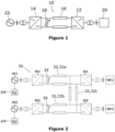
- a point-to-point power transmission scheme is shown in Figure 1 and is designated generally by the reference numeral 10.
- the point-to-point power transmission scheme 10 comprises a sending end power converter 12, a receiving end power converter 14, a DC link 16 and a dynamic braking system (DBS) 18.
- Each of the sending end and receiving end power converters 12,14 is an AC/DC power converter.
- an AC side of the sending end power converter 12 is connected to an AC power source 20, such as a wind farm or other energy generator, while the receiving end power converter 14 is connected to an AC power load 22, such as an AC power grid.
- the DC link 16 is in the form of a pair of DC power transmission lines interconnecting DC sides of the sending end and receiving end power converters 12,14.
- the DBS 18 defines a conduction path that is connected in shunt between the DC power transmission lines.
- the sending end power converter 12 receives AC power from the AC power source 20 and converts it into DC power that is transferred into the DC link 16.
- the DC link 16 then transmits the DC power to the receiving end power converter 14 that converts it into AC power before transferring it to the AC power load 22.
- the net power exchange of the point-to-point power transmission scheme 10 must be zero on average, which means that power injected into the sending end power converter 12 must be matched by the power extracted from the receiving end power converter 14 as closely as possible to minimise any surplus in injected power.
- the DBS 18 is activated to draw energy from the DC power transmission lines in order to avoid the need to take the point-to-point power transmission scheme 10 offline.
- multi-terminal power transmission schemes typically comprise multiple sending end power converters associated with respective AC power sources, multiple receiving end power converters associated with respective AC power loads, multiple DC links interconnecting the sending end and receiving end power converters, and multiple dynamic braking systems (DBSes) connected to respective DC links.
- each DBS is typically associated with a respective receiving end power converter and hence is designed to carry out a dynamic braking operation when the corresponding receiving end power converter is incapable of transferring an expected power from the DC link to the corresponding AC power load.
- any such event adversely affecting the power transfer capability of one or more receiving end power converters will have a global effect on all DC nodes of a given multi-terminal power transmission scheme and hence might trigger activation of multiple DBSes.
- each such DBS might not be designed to carry out a dynamic braking operation during all transient events that adversely affect the power transfer capability of other receiving end power converters associated with other DBSes. It can be difficult to select a suitable rating for each individual DBS that takes into account not only ratings and control methods of other DBSes in the multi-terminal power transmission schemes but also requirements of the AC systems to which the corresponding receiving end power converters are connected.
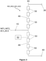
- FIG. 2 An electrical assembly in the form of a multi-terminal power transmission scheme according to an embodiment of the invention is shown in Figure 2 and is designated generally by the reference numeral 30.
- the multi-terminal power transmission scheme 30 comprises a plurality of sending end power converters SE1, SE2, a plurality of receiving end power converters RE1, RE2, a plurality of DC links 32 and a plurality of DBSes 34,36.
- Each of the sending end and receiving end power converters SE1,SE2,RE1,RE2 is an AC/DC power converter having AC and DC sides.
- Each power converter SE1,SE2,RE1,RE2 includes first and second DC terminals 38,40 that define the DC side of the power converter SE1,SE2,RE1,RE2.
- Each power converter SE1,SE2,RE1,RE2 includes a plurality of AC terminals 42 that defines the AC side of the power converter. More particularly, each power converter SE1,SE2,RE1,RE2 includes a plurality of converter limbs 44, each of which is arranged as shown in Figure 2 .
- Each converter limb 44 extends between the first and second DC terminals 38,40.
- Each converter limb 44 includes a first limb portion 46 that extends between the first DC terminal 38 and the AC terminal 42, and a second limb portion 48 which extends between the second DC terminal 40 and the AC terminal 42.
- Each limb portion 46,48 includes a plurality of series-connected switching elements 50, each of which is in the form of a thyristor. It is envisaged that, in other embodiments of the invention, the plurality of series-connected switching elements 50 in each limb portion 46,48 may be replaced by one or more other types of semiconductor switches, such as IGBTs.
- each power converter SE1,SE2,RE1,RE2 is merely chosen to help illustrate the operation of the invention and that each power converter SE1,SE2,RE1,RE2 may be replaced by another converter with a different topology.
- each power converter SE1,SE2,RE1,RE2 may be configured as a chain-link converter, such as the Modular Multilevel Converter (MMC) or the Alternate Arm Converter (AAC).
- MMC Modular Multilevel Converter
- AAC Alternate Arm Converter
- Each power converter SE1,SE2,RE1,RE2 includes a converter controller 52 that is programmed to control operation of the power converter SE1,SE2,RE1,RE2.
- the converter controllers 52 may be implemented as separate converter controllers 52 or may be implemented as part of the same converter control system.
- Each converter controller 52 may be configured to communicate with at least one other converter controller 52 via telecommunications links and/or a central controller (also known as a global controller).
- each sending end power converter SE1,SE2 is connected to a respective AC power source WF1,WF2, such as a wind farm or other energy generator, via a transformer.
- the AC side of each receiving end power converter RE1,RE2 is connected to a respective AC power load AC1,AC2, such as an AC power grid, via a transformer.
- a first DC link 32,32a interconnects the DC sides of a first sending end power converter SE1 and a first receiving end power converter RE1.
- a second DC link 32,32b interconnects the DC sides of a second sending end power converter SE2 and a second receiving end power converter RE2.
- a third DC link 32,32c interconnects the DC sides of the first and second sending end power converters SE1,SE2.
- Each DC link 32 is in the form of a pair of DC power transmission lines. In this way the plurality of DC links 32 interconnect the DC sides of the power converters SE1,SE2,RE1,RE2 in a multi-terminal power transmission network configuration.
- a first DBS 34 defines a conduction path that is connected in shunt between the DC power transmission lines of the first DC link 32,32a and is connected at the end of the first DC link 32,32a connected to the first receiving end power converter RE1.
- a second DBS 36 defines a conduction path that is connected in shunt between the DC power transmission lines of the second DC link 32,32b and is connected at the end of the second DC link 32,32b connected to the second receiving end power converter SE2.
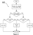
- FIG. 3 shows the structure of each DBS 34,36.
- the conduction path of each DBS 34,36 includes a plurality of series-connected current flow control elements 54 connected in series with an energy dissipation element 56.
- Each DBS 34,36 includes a dynamic braking control unit 58 programmed to selectively control activation of the current flow control elements 54 to permit current to flow through the conduction path.
- Each current flow control element 54 is in the form of an IGBT. In other embodiments of the invention, it is envisaged that the IGBT may be replaced by a different semiconductor switching element.
- the energy dissipation element 56 is in the form of a resistor.
- the energy dissipation element 56 may be replaced by a plurality of energy dissipation elements, a single energy storage element or a plurality of energy storage elements.
- the or each energy storage element may be a capacitor, a fuel cell or a battery.
- Each DBS 34,36 is configured to have a conditional operation capability based on different activation triggers and different operating states of the AC power load AC1,AC2 connected to the corresponding receiving end power converter RE1,RE2. This enables coordination of multiple DBSes 34,36 to broaden the overall dynamic braking operation capability of the multi-terminal power transmission scheme 30, which is described as follows with reference to Figures 5 to 8 .
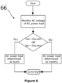
- FIG. 5 shows a control algorithm 60 for the conditional operation capability of each DBS 34,36.
- the multi-terminal power transmission scheme 30 includes a plurality of monitoring units 62.
- Each monitoring unit 62 is configured for monitoring an electrical parameter of a respective one of the AC power loads AC1,AC2.
- the configuration of each monitoring unit 62 depends on the type of electrical parameter of the AC power load AC1,AC2 that is being monitored.
- each monitoring unit 62 may include a voltage sensor for monitoring an AC voltage of the AC power load AC1,AC2, or each monitoring unit 62 may include a current sensor for monitoring an AC current of the AC power load AC1,AC2.
- the multi-terminal power transmission scheme 30 includes a plurality of processing units 64.
- Each processing unit 64 is configured to receive the monitored electrical parameter from the corresponding monitoring unit 62, e.g. via telecommunications links and/or a central controller.
- Each processing unit 64 is programmed to determine an operating state of the corresponding AC power load AC1,AC2 from the corresponding monitored electrical parameter.
- each processing unit 64 is programmed to determine the operating state of the corresponding AC power load AC1,AC2 as a faulty operating state when the monitored electrical parameter is not at a reference electrical parameter value or is not within a reference electrical parameter range, and as a healthy operating state when the monitored electrical parameter is at a reference electrical parameter value or is within a reference electrical parameter range.
- Each dynamic braking control unit 58 is programmed to be responsive to the determined operating state of the corresponding AC power load AC1,AC2 by configuring the corresponding current flow control elements 54 to be activatable by different activation triggers depending on the nature of the determined operating state of the corresponding AC power load AC1,AC2. If the determined operating state of the corresponding AC power load AC1,AC2 is a faulty operating state, then the dynamic braking control unit 58 is programmed to configure the corresponding current flow control elements 54 to be activatable by a first activation trigger and inhibited from being activated by a second activation trigger.
- the dynamic braking control unit 58 is programmed to configure the corresponding current flow control elements 54 to be activatable by the second activation trigger and inhibited from being activated by the first activation trigger.
- the current flow control elements 54 of a given DBS 34,36 are configured to be activatable by the first activation trigger (i.e. the associated AC power load has a faulty operating state) and a first condition 'Condition1' is met, then the current flow control elements 54 of the given DBS 34,36 are activated by the first activation trigger to begin the dynamic braking operation.
- the current flow control elements 54 of the given DBS 34,36 are configured to be activatable by the second activation trigger (i.e. the associated AC power load AC1,AC2 has a healthy operating state) and a second condition 'Condition2' is met, then the current flow control elements 54 of the given DBS 34,36 are activated by the second activation trigger to begin the dynamic braking operation.
- the current flow control elements 54 of the given DBS 34,36 are configured to be activatable by the first activation trigger and a first condition 'Condition1' is not met, then the current flow control elements 54 of the given DBS 34,36 stay deactivated to inhibit the dynamic braking operation. Similarly, if the current flow control elements 54 of the given DBS 34,36 are configured to be activatable by the second activation trigger and a second condition 'Condition2' is not met, then the current flow control elements 54 of the given DBS 34,36 stay deactivated to inhibit the dynamic braking operation.
- the processing unit 64 and the dynamic braking control unit 58 form part of a local controller of the dynamic braking system 34,36.
- the processing unit 64 may be external to the dynamic braking control unit 58 and may be configured to communicate the determined operating state of the corresponding AC power load AC1,AC2 to the dynamic braking control unit 58 via telecommunications links and/or the central controller.
- the processing unit 64 may form part of the converter controller 52.
- Figure 6 illustrates a control algorithm 66 for determining an operating state of an AC power load AC1,AC2 of the multi-terminal power transmission scheme 30.
- the operating state of the AC power load AC1,AC2 is determined by comparing its AC voltage Vac with a reference AC voltage range having a maximum AC voltage threshold Vac,max and a minimum AV voltage threshold Vac,min.
- the AC voltage Vac of the AC power load AC1,AC2 may be measured at, for example, a grid access point of the associated receiving end power converter RE1,RE2.
- the reference AC voltage range represents a normal AC voltage operating range of the AC power load AC1,AC2. If the AC voltage Vac is within the reference AC voltage range, then the AC power load AC1,AC2 is determined to have a healthy operating state. If the AC voltage Vac is lower or higher than the reference AC voltage range, then the AC power load AC1,AC2 is determined to have a faulty operating state.
- other non-limiting ways of determining the operating state of the AC power load AC1,AC2 is by configuring the monitoring unit to monitor one or more of: an impedance of the AC power load AC1,AC2, an AC current of the AC power load AC1,AC2, a rate of change of AC current of the AC power load AC1,AC2, a frequency of the AC power load AC1,AC2 and a rate of change of frequency of the AC power load AC1,AC2.
- the control algorithm 62 of Figure 6 applies mutatis mutandis to these other electrical parameters of the AC power load AC1,AC2.
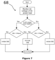
- FIG 7 illustrates a control algorithm 68 for the conditional operation capability of each DBS 34,36.
- Each processing unit 64 determines the operating state of the corresponding AC power load AC1,AC2 as being faulty or healthy in accordance with the control algorithm 66 of Figure 6 .
- Each DBS 34,36 includes a voltage sensor for measuring a DC voltage of the corresponding DC link 32, i.e. a DC voltage across the conduction path. Such voltage measurement may be continuous, discontinuous or intermittent. It will be appreciated that the voltage sensor may be external to the DBS 34,36.
- the first activation trigger of each DBS 34,36 is configured to correspond to the DC voltage of the corresponding DC link 32 exceeding a first reference DC voltage threshold.
- the first reference DC voltage threshold is set above a steady-state operating DC voltage of the DC link 32 and is typically set to be equal or higher than the highest allowed continuous operating voltage of the DC link 32.
- the current flow control elements 54 are activated by the first activation trigger to begin the dynamic braking operation.
- the current flow control elements 54 of the given DBS 34,36 stay deactivated to inhibit the dynamic braking operation.
- Both sending end power converters SE1,SE2 inject positive powers PSE1,PSE2 into the respective DC links 32.
- the DBS 34 associated with the receiving end power converter RE1 is activated by the first activation trigger to carry out the dynamic braking operation and thereby dissipate the excess power. Meanwhile, since the AC power load AC2 associated with the receiving end power converter RE2 is determined to be healthy, the DBS 36 associated with the receiving end power converter RE2 is inhibited from being activated by the first activation trigger and thereby does not carry out the dynamic braking operation provided that its current flow control elements 54 are not activated by the second activation trigger.
- the DBS 36 associated with the receiving end power converter RE2 is activated by the first activation trigger to carry out the dynamic braking operation while the DBS 34 associated with the receiving end power converter RE1 is inhibited from being activated by the first activation trigger provided that its current flow control elements are not activated by the second activation trigger.
- the DBS 34,36 associated with the corresponding receiving end power converter RE1,RE2 is the preferred DBS for carrying out the dynamic braking operation while the DBS 34,36 associated with the other receiving end power converter RE1,RE2 is the non-preferred DBS for carrying out the dynamic braking operation.
- the first activation trigger may correspond to a power difference between a target power exchange level of the corresponding receiving end power converter RE1,RE2 and a measured power exchange level of the corresponding receiving end power converter RE1,RE2 exceeding a reference power difference threshold.
- the target power exchange level of the receiving end power converter RE1,RE2 may be a calculated, predicted, expected or designed power exchange level of the receiving end power converter RE1,RE2. If the power difference stays below the reference power difference threshold, then the measured power exchange level is considered to be close enough to the target power exchange level to enable normal operation of the receiving end power converter RE1,RE2.
- the reduction in power PRE1 extracted by the receiving end power converter RE1 to zero would result in the power difference exceeding the reference power difference threshold.
- the DBS 36 associated with the receiving end power converter RE2 is inhibited from being activated by the first activation trigger because the power PRE2 extracted by the receiving end power converter RE2 is unchanged, which means that the power difference between a target power exchange level of the receiving end power converter RE2 and a measured power exchange level of the receiving end power converter RE2 stays below the reference power difference threshold.
- the second activation trigger enables a given DBS 34,36 to respond to an event of a remote faulty AC power load in case the preferred DBS 34,36 is unavailable for dynamic braking operation. More particularly, the second activation trigger is configured to correspond to the DC voltage Vdc of the corresponding DC link 32 exceeding a second reference DC voltage threshold Vmax2 that is higher than the first reference DC voltage threshold Vmax1. If the DC voltage Vdc of the DC link 32 exceeds the second reference DC voltage threshold Vmax2, the current flow control elements 54 of the associated DBS 34,36 are activated by the second activation trigger provided that the associated AC power load AC1,AC2 is determined to be healthy.
- the DBS 34 associated with the receiving end power converter RE1 carries out the dynamic braking operation based on activation by the first activation trigger while the DBS 36 associated with the receiving end power converter RE2 is inhibited from being activated by the first activation trigger but is activatable by the second activation trigger due to the associated AC power load AC2 being healthy.
- the DBS 34 associated with the receiving end power converter RE1 is not available (e.g. due to a malfunction or lacking sufficient energy dissipation capability)
- the DC voltage Vdc of the DC links 32 will continue to rise due to the non-zero net power of the DC links 32 until it exceeds the second reference DC voltage threshold Vmax2.
- the DBS 36 associated with the receiving end power converter RE2 carries out the dynamic braking operation based on activation by the second activation trigger, as shown in Figure 7 .
- the voltage stress experienced by the multi-terminal power transmission scheme 30 during the dynamic braking operation of a DBS 34,36 activated by the second activation trigger would be higher than the voltage stress experienced by the multi-terminal power transmission scheme 30 during the dynamic braking operation of the DBS 34,36 activated by the first activation trigger.
- the dynamic braking control unit 58 may be programmed to reduce the first reference DC voltage threshold Vmax1 if the determined operating state of the AC power load AC1,AC2 is a faulty operating state.
- the dynamic braking control unit 58 is programmed to configure the first reference DC voltage threshold Vmax1 as a function of an AC voltage of the AC power load AC1,AC2 so as to:
- the reduction of the first reference DC voltage threshold Vmax1 may be proportional to a difference between the AC voltage of the AC power load AC1,AC2 and the reference AC voltage value or range. Hence, for a less severe AC fault in the AC power load AC1,AC2 resulting in a smaller AC voltage reduction, a corresponding reduction is applied to the first reference DC voltage threshold Vmax1.
- This approach has the benefit of permitting a reduction of the second reference DC voltage threshold Vmax2 to reduce stress on the multi-terminal power transmission scheme while maintaining a sufficiently large voltage offset between the first and second reference DC voltage thresholds Vmax1,Vmax2 to ensure selectivity between preferred and non-preferred DBSes 34,36 to enable a preferred DBS 34,36, if available, to activate first before a non-preferred DBS 34,36.
- the first reference DC voltage threshold Vmax1 may be configured to have a first time-varying DC voltage profile in which the first reference DC voltage threshold Vmax1 increases with time. This not only helps to initially maintain the desired selectivity between preferred and non-preferred DBSes 34,36 but also allows the reduced first reference DC voltage threshold Vmax1 to eventually return to its original value.
- Selectivity between preferred and non-preferred DBSes 34,36 may be further enhanced by programming the dynamic braking control unit 58 to configure the current flow control elements 54 to be: activatable by the first activation trigger and inhibited from being activated by the second activation trigger during an activation time delay; and activatable by the second activation trigger after the activation time delay.
- the second reference DC voltage threshold Vmax2 may be configured to have a second time-varying DC voltage profile in which the second reference DC voltage threshold Vmax2 decreases with time. This not only helps to initially maintain the desired selectivity between preferred and non-preferred DBSes 34,36 but also reduces voltage stress on the multi-terminal power transmission scheme 30 if it turns out that the non-preferred DBS 34,36 is required to carry out the dynamic braking operation.
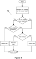
- FIG 8 illustrates another control algorithm 70 for the conditional operation capability of each DBS 34,36.
- Each processing unit 64 determines the operating state of the corresponding AC power load AC1,AC2 as being faulty or healthy in accordance with the control algorithm 66 of Figure 6 .
- the first activation trigger of each DBS 34,36 is configured to correspond to the DC voltage Vdc of the corresponding DC link 32 exceeding the first reference DC voltage threshold Vmax1.
- the second activation trigger for a given DBS 34,36 corresponds to a combination of an unavailable operating status of the other DBS 34,36 and the DC voltage Vdc of the corresponding DC link 32 exceeding the first reference DC voltage threshold Vmax1.
- the control algorithm 70 first checks whether an indication of an unavailable operating status of the other DBS 34,36 has been obtained. If the other DBS has an available operating status, then the given DBS is not activated by the second activation trigger. If the other DBS 34,36 has an unavailable operating status, the control algorithm then checks whether the DC voltage Vdc of the corresponding DC link 32 exceeds the first reference DC voltage threshold Vmax1.
- the given DBS 32 is activated by the second activation trigger to carry out the dynamic braking operation. If the DC voltage Vdc of the corresponding DC link 32 does not exceed the first reference DC voltage threshold Vmax1, then the given DBS 32 is not activated by the second activation trigger.
- the available DBS 34,35 is permitted to be activated by the DC voltage Vdc of the corresponding DC link 32 exceeding the first reference DC voltage threshold Vmax1 irrespective of whether the corresponding AC power load AC1,AC2 is faulty or healthy.
- This approach maintains the desired selectivity between preferred and non-preferred DBSes 34,36 while using the first reference DC voltage threshold Vmax1 as a means for selective activation of the DBSes 34,36, which has the effect of reducing voltage stress on the multi-terminal power transmission scheme 30.
- the unavailable operating status of a DBS 34,36 may relate, but is not limited, to the other DBS 34,36:
- the dynamic braking control unit 58 may obtain the indication of an unavailable operating status of the other DBS 34,36, e.g. via telecommunications links, by:
- the DBS 34 associated with the receiving end power converter RE1 has an unavailable operating status
- the DBS 36 associated with the other receiving end power converter RE2 will be activated by the second activation trigger even though its associated AC power load AC2 is deemed to be healthy.
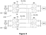
- FIG. 9 An electrical assembly in the form of a multi-terminal power transmission scheme according to another embodiment of the invention is shown in Figure 9 and is designated generally by the reference numeral 130.
- the multi-terminal power transmission scheme 130 of Figure 9 is similar in structure and operation to the multi-terminal power transmission scheme 30 of Figure 2 and like features share the same reference numerals.
- the multi-terminal power transmission scheme 130 of Figure 9 differs from the multi-terminal power transmission scheme 30 of Figure 2 in that the multi-terminal power transmission scheme 130 of Figure 9 is configured in a bipole configuration with a return path in which:
- each DBS 34,36,72,74,76,78 has therefore devised a solution that configures the activation of each DBS 34,36,72,74,76,78 to be more selective towards its own receiving end.
- the provision of the second activation trigger allows utilisation of any remaining capability of one or more non-preferred DBSes 34,36,72,74,76,78 to carry out the dynamic braking operation and thereby enables the electrical assembly 30,130 of the invention to be responsive to circumstances in which the preferred DBS 34,36,72,74,76,78 is unavailable.
- the use of the first and second activation triggers for triggering DBS activation avoids the risk of outage of an entire multi-terminal power transmission scheme due to the non-availability of a preferred DBS and due to each DBS being only capable of responding to fault events affecting the corresponding AC power load.
- the difference between the coordinated multiple DBS control of the invention and the conventional uncoordinated multiple DBS control is that the former involves activation of a non-preferred DBS in response to a remote network event only under some specific circumstances, which in certain configurations of the invention can be rare, while the latter involves activation of multiple DBSes in response to a remote network event every time due to the global effect of a fault affecting the power transfer capability of a given receiving end power converter.
- design requirements of each DBS 34,36,72,74,76,78 can be optimised to deliver a certain minimum performance as required by the corresponding receiving end power converter RE1,RE2 and AC power load AC1,AC2 with which it is associated, where the influence of other receiving end power converters RE1,RE2 and AC power loads AC1,AC2 on such design requirements are significantly reduced.
- the simulations of the test scenarios were done for full load conditions, i.e. with 1 per-unit power injected by each sending end power converter SE1,SE2 and with 1 per-unit power transferred by each receiving end power converter RE1,RE2 to its associated AC power load.
- the simulation results for the first two tests confirmed that the DBSes 72,74,76,78 associated with the faulty AC power load AC1,AC2 responded first to carry out the dynamic braking operation.
- the simulation results for the second two tests confirmed that, in the event of an outage at a receiving end power converter RE1,RE2, the DBSes 72,74,76,78 associated with the other unaffected receiving end power converter RE1,RE2 is activated to carry out the dynamic braking operation although the associated AC power load AC1,AC2 is in a healthy operating state.
- the multi-terminal power transmission schemes 30,130 may alternatively or additionally include dynamic braking systems associated with sending end power converters SE1,SE2, where one or more of the dynamic braking systems associated with the sending end power converters SE1,SE2 may be configured to have the conditional operation capability based on different activation triggers and different operating states of the AC power sources WF1,WF2.
- Non-limiting examples of additional or alternative features of the electrical assembly of the invention are described throughout the specification. One or more of the additional and alternative features may be applied to, or incorporated into, the multi-terminal power transmission schemes 30,130.
Claims (16)
- Ensemble électrique (30, 130) comprenant :un convertisseur de puissance (RE1, RE2) présentant un côté CA et un côté CC, le côté CA étant destiné à une connexion à un réseau CA (AC1, AC2) ;au moins un support de transmission de puissance (32) connecté au côté CC du convertisseur de puissance (RE1, RE2) ;un système de freinage dynamique (34, 36, 72, 74, 76, 78) connecté de manière fonctionnelle au ou à chaque support de transmission de puissance (32), le système de freinage dynamique (34, 36, 72, 74, 76, 78) incluant une unité de commande de freinage dynamique (58) programmée pour commander sélectivement l'activation du système de freinage dynamique (34, 36, 72, 74, 76, 78) afin d'effectuer une opération de freinage dynamique ;une unité de surveillance (62) pour surveiller un paramètre électrique du réseau CA (AC1, AC2) ; etune unité de traitement (64) programmée pour déterminer un état de fonctionnement du réseau CA (AC1, AC2) à partir du paramètre électrique surveillé,caractérisé en ce que l'unité de commande de freinage dynamique (58) est programmée pour réagir à l'état de fonctionnement déterminé du réseau CA (AC1, AC2) de telle sorte que :(i) si l'état de fonctionnement déterminé du réseau CA (AC1, AC2) est un état de fonctionnement défectueux, le système de freinage dynamique soit configuré pour être activable par un premier déclencheur d'activation ; et(ii) si l'état de fonctionnement déterminé du réseau CA (AC1, AC2) est un état de fonctionnement sain, le système de freinage dynamique soit configuré pour être activable par un second déclencheur d'activation.
- Ensemble électrique (30, 130) selon la revendication 1, incluant une pluralité de convertisseurs de puissance (RE1, RE2) et une pluralité de supports de transmission de puissance (32), le côté CA de chaque convertisseur de puissance (RE1, RE2) pour une connexion à un réseau CA respectif (AC1, AC2), la pluralité de supports de transmission de puissance (32) interconnectant les côtés CC des convertisseurs de puissance (RE1, RE2) dans une configuration de réseau de transmission de puissance multiterminal, l'ensemble électrique (30, 130) incluant une pluralité de systèmes de freinage dynamique (34, 36, 72, 74, 76, 78), chaque système de freinage dynamique (34, 36, 72, 74, 76, 78) correspondant à l'un respectif des réseaux CA (AC1, AC2),dans lequel l'ensemble électrique (30, 130) inclut une pluralité d'unités de surveillance (62), chaque unité de surveillance (62) étant configurée pour surveiller un paramètre électrique de l'un respectif des réseaux CA (AC1, AC2),dans lequel l'ensemble électrique (30, 130) inclut une pluralité d'unités de traitement (64), chaque unité de traitement (64) étant programmée pour déterminer un état de fonctionnement du réseau CA correspondant (AC1, AC2) à partir du paramètre électrique surveillé correspondant, dans lequel chaque unité de commande de freinage dynamique (58) est programmée pour réagir à l'état de fonctionnement déterminé du réseau CA correspondant (AC1, AC2) en configurant le système de freinage dynamique correspondant (34, 36, 72, 74, 76, 78) pour qu'il soit activable :(i) par un premier déclencheur d'activation respectif si l'état de fonctionnement déterminé du réseau CA correspondant (AC1, AC2) est un état de fonctionnement défectueux ; et(ii) par un second déclencheur d'activation respectif si l'état de fonctionnement déterminé du réseau CA correspondant (AC1, AC2) est un état de fonctionnement sain.
- Ensemble électrique selon la revendication 2, dans lequel les premier et second déclencheurs d'activation des systèmes de freinage dynamique sont sélectionnés pour être différents de manière à permettre la coordination des activations des systèmes de freinage dynamique pour effectuer leurs opérations de freinage dynamique respectives.
- Ensemble électrique (30, 130) selon l'une quelconque des revendications précédentes, dans lequel l'unité de traitement (64) est programmée pour déterminer l'état de fonctionnement du réseau CA (AC1, AC2) comme :(i) un état de fonctionnement défectueux lorsque le paramètre électrique surveillé n'est pas à une valeur de paramètre électrique de référence ou n'est pas dans une plage de paramètre électrique de référence ; et(ii) un état de fonctionnement sain lorsque le paramètre électrique surveillé est à une valeur de paramètre électrique de référence ou est dans une plage de paramètre électrique de référence.
- Ensemble électrique (30, 130) selon l'une quelconque des revendications précédentes, dans lequel le premier déclencheur d'activation correspond à une tension CC (Vdc) du ou de chaque support de transmission de puissance (32) dépassant un premier seuil de tension CC de référence (Vmax1).
- Ensemble électrique (30, 130) selon la revendication 5, dans lequel l'unité de commande de freinage dynamique (58) est programmée pour réduire le premier seuil de tension CC de référence (Vmax1) si l'état de fonctionnement déterminé du réseau CA (AC1, AC2) est un état de fonctionnement défectueux.
- Ensemble électrique (30, 130) selon la revendication 5 ou la revendication 6, dans lequel l'unité de commande de freinage dynamique (58) est programmée pour configurer le premier seuil de tension CC de référence (Vmax1) en fonction d'une tension CA du réseau CA (AC1, AC2).
- Ensemble électrique (30, 130) selon la revendication 7, dans lequel l'unité de commande de freinage dynamique (58) est programmée pour :(i) réduire le premier seuil de tension CC de référence (Vmax1) lorsque la tension CA du réseau CA (AC1, AC2) n'est pas à une valeur de tension CA de référence ou n'est pas dans une plage de tension CA de référence ; et(ii) maintenir le premier seuil de tension CC de référence (Vmax1) lorsque la tension CA du réseau CA (AC1, AC2) est à une valeur de tension CA de référence ou est dans une plage de tension CA de référence.
- Ensemble électrique (30, 130) selon la revendication 8, dans lequel l'unité de commande de freinage dynamique (58) est programmée pour réduire le premier seuil de tension CC de référence (Vmax1) d'une quantité proportionnelle à une différence entre la tension CA du réseau CA (AC1, AC2) et la valeur ou la plage de tension CA de référence lorsque la tension CA du réseau CA (AC1, AC2) n'est pas à la valeur de tension CA de référence ou n'est pas dans la plage de tension CA de référence.
- Ensemble électrique (30, 130) selon l'une quelconque des revendications 5 à 9, dans lequel le premier seuil de tension CC de référence (Vmax1) est configuré pour présenter un premier profil de tension CC variant dans le temps dans lequel le premier seuil de tension CC de référence (Vmax1) varie dans le temps.
- Ensemble électrique (30, 130) selon l'une quelconque des revendications précédentes, dans lequel le second déclencheur d'activation correspond à une tension CC (Vdc) du ou de chaque support de transmission de puissance (32) dépassant un second seuil de tension CC de référence (Vmax2).
- Ensemble électrique (30, 130) selon la revendication 11 lorsqu'elle dépend de l'une quelconque des revendications 5 à 10, dans lequel le second seuil de tension CC de référence (Vmax2) est supérieur au premier seuil de tension CC de référence (Vmax1).
- Ensemble électrique (30, 130) selon la revendication 11 ou la revendication 12, dans lequel le second seuil de tension CC de référence (Vmax2) est configuré pour présenter un second profil de tension CC variant dans le temps dans lequel le second seuil de tension CC de référence (Vmax2) varie dans le temps.
- Ensemble électrique (30, 130) selon l'une quelconque des revendications précédentes, dans lequel l'unité de commande de freinage dynamique (58) est programmée pour configurer le système de freinage dynamique (34, 36, 72, 74, 76, 78) pour :(i) être activable par le premier déclencheur d'activation et être empêché d'être activé par le second déclencheur d'activation pendant un délai d'activation ; et(ii) être activable par le second déclencheur d'activation après le délai d'activation.
- Ensemble électrique (30, 130) selon l'une quelconque des revendications précédentes, dans lequel le premier déclencheur d'activation correspond à une différence de puissance entre un niveau d'échange de puissance cible du convertisseur de puissance (RE1, RE2) et un niveau d'échange de puissance mesuré du convertisseur de puissance (RE1, RE2) dépassant un seuil de différence de puissance de référence.
- Ensemble électrique (30, 130) selon l'une quelconque des revendications précédentes, dans lequel le second déclencheur d'activation correspond à un état de fonctionnement indisponible d'un autre système de freinage dynamique (34, 36, 72, 74, 76, 78).
Priority Applications (3)
| Application Number | Priority Date | Filing Date | Title |
|---|---|---|---|
| EP21275056.6A EP4089869B1 (fr) | 2021-05-10 | 2021-05-10 | Ensemble électrique |
| CN202210503340.0A CN115333134A (zh) | 2021-05-10 | 2022-05-10 | 电组合件 |
| US17/741,078 US20220360161A1 (en) | 2021-05-10 | 2022-05-10 | Electrical assembly |
Applications Claiming Priority (1)
| Application Number | Priority Date | Filing Date | Title |
|---|---|---|---|
| EP21275056.6A EP4089869B1 (fr) | 2021-05-10 | 2021-05-10 | Ensemble électrique |
Publications (2)
| Publication Number | Publication Date |
|---|---|
| EP4089869A1 EP4089869A1 (fr) | 2022-11-16 |
| EP4089869B1 true EP4089869B1 (fr) | 2024-04-17 |
Family
ID=75904833
Family Applications (1)
| Application Number | Title | Priority Date | Filing Date |
|---|---|---|---|
| EP21275056.6A Active EP4089869B1 (fr) | 2021-05-10 | 2021-05-10 | Ensemble électrique |
Country Status (3)
| Country | Link |
|---|---|
| US (1) | US20220360161A1 (fr) |
| EP (1) | EP4089869B1 (fr) |
| CN (1) | CN115333134A (fr) |
Family Cites Families (1)
| Publication number | Priority date | Publication date | Assignee | Title |
|---|---|---|---|---|
| EP3206286A1 (fr) * | 2016-02-10 | 2017-08-16 | GE Energy Power Conversion Technology Ltd | Commande de grille operée avec surtension pour conduire et commuter des courants de choc dans des commutateurs igbt |
-
2021
- 2021-05-10 EP EP21275056.6A patent/EP4089869B1/fr active Active
-
2022
- 2022-05-10 US US17/741,078 patent/US20220360161A1/en active Pending
- 2022-05-10 CN CN202210503340.0A patent/CN115333134A/zh active Pending
Also Published As
| Publication number | Publication date |
|---|---|
| US20220360161A1 (en) | 2022-11-10 |
| EP4089869A1 (fr) | 2022-11-16 |
| CN115333134A (zh) | 2022-11-11 |
Similar Documents
| Publication | Publication Date | Title |
|---|---|---|
| KR102082105B1 (ko) | 컨버터 기반 dc 배전 시스템들에서의 폴트 보호 | |
| Babaei et al. | A survey on fault detection, isolation, and reconfiguration methods in electric ship power systems | |
| EP2827158B1 (fr) | Procédé et système de commande et de protection de systèmes sous-marins d'alimentation en courant direct | |
| EP3553911B1 (fr) | Système de microréseau et procédé de gestion de dysfonctionnement | |
| JP7176000B2 (ja) | 電力グリッドシステム | |
| EP3107171B1 (fr) | Techniques de protection contre les pannes zonales de systèmes de distribution de courant continu | |
| JP4776475B2 (ja) | 電力系統連系システム | |
| US10615587B2 (en) | Bipolar DC power transmission scheme | |
| US10673230B2 (en) | Bipolar DC power transmission scheme | |
| ES2824841T3 (es) | Procedimiento para hacer funcionar una red de suministro de energía eléctrica y un equipo de control para controlar equipos de una red de distribución eléctrica | |
| WO2013098932A1 (fr) | Système de batterie et dispositif de détection de défaut à la terre | |
| US20210203185A1 (en) | Power distribution systems and methods | |
| Abdali et al. | Fast fault detection and isolation in low-voltage DC microgrids using fuzzy inference system | |
| US9419428B2 (en) | Protection device for DC collection systems | |
| Yadav et al. | Short-circuit fault detection and isolation using filter capacitor current signature in low-voltage DC microgrid applications | |
| US20140032009A1 (en) | Power distribution system and method for operation thereof | |
| EP4089869B1 (fr) | Ensemble électrique | |
| Dahiwale et al. | Review on fault management in hybrid microgrid | |
| CN113632334A (zh) | 使用直流互联系统的馈电线故障响应 | |
| Haritha et al. | Communication assisted coordinated protection scheme for DC microgrid | |
| Dahiwale et al. | Fault management scheme for islanded DC microgrid | |
| Abdali et al. | Novel method of low and high impedance fault detection in LVDC microgrids | |
| Ghazanfari et al. | A decentralized control strategy with dc fault handling capability for smart dc buildings | |
| Tejaswi et al. | Protection in Smart Building: Mini Review | |
| JPWO2013098932A1 (ja) | 電池システム、および地絡検知装置 |
Legal Events
| Date | Code | Title | Description |
|---|---|---|---|
| PUAI | Public reference made under article 153(3) epc to a published international application that has entered the european phase |
Free format text: ORIGINAL CODE: 0009012 |
|
| STAA | Information on the status of an ep patent application or granted ep patent |
Free format text: STATUS: THE APPLICATION HAS BEEN PUBLISHED |
|
| AK | Designated contracting states |
Kind code of ref document: A1 Designated state(s): AL AT BE BG CH CY CZ DE DK EE ES FI FR GB GR HR HU IE IS IT LI LT LU LV MC MK MT NL NO PL PT RO RS SE SI SK SM TR |
|
| STAA | Information on the status of an ep patent application or granted ep patent |
Free format text: STATUS: REQUEST FOR EXAMINATION WAS MADE |
|
| 17P | Request for examination filed |
Effective date: 20230321 |
|
| RBV | Designated contracting states (corrected) |
Designated state(s): AL AT BE BG CH CY CZ DE DK EE ES FI FR GB GR HR HU IE IS IT LI LT LU LV MC MK MT NL NO PL PT RO RS SE SI SK SM TR |
|
| STAA | Information on the status of an ep patent application or granted ep patent |
Free format text: STATUS: EXAMINATION IS IN PROGRESS |
|
| 17Q | First examination report despatched |
Effective date: 20230530 |
|
| P01 | Opt-out of the competence of the unified patent court (upc) registered |
Effective date: 20230522 |
|
| REG | Reference to a national code |
Ref country code: DE Ref legal event code: R079 Ref document number: 602021011909 Country of ref document: DE Free format text: PREVIOUS MAIN CLASS: H02J0001100000 Ipc: H02M0005450000 Ref legal event code: R079 Ipc: H02M0005450000 |
|
| GRAP | Despatch of communication of intention to grant a patent |
Free format text: ORIGINAL CODE: EPIDOSNIGR1 |
|
| RIC1 | Information provided on ipc code assigned before grant |
Ipc: H02M 1/32 20070101ALI20231002BHEP Ipc: H02M 7/483 20070101ALI20231002BHEP Ipc: H02J 3/36 20060101ALI20231002BHEP Ipc: H02J 1/10 20060101ALI20231002BHEP Ipc: H02M 5/458 20060101ALI20231002BHEP Ipc: H02M 5/45 20060101AFI20231002BHEP |
|
| STAA | Information on the status of an ep patent application or granted ep patent |
Free format text: STATUS: GRANT OF PATENT IS INTENDED |
|
| INTG | Intention to grant announced |
Effective date: 20231109 |
|
| GRAS | Grant fee paid |
Free format text: ORIGINAL CODE: EPIDOSNIGR3 |
|
| GRAA | (expected) grant |
Free format text: ORIGINAL CODE: 0009210 |
|
| STAA | Information on the status of an ep patent application or granted ep patent |
Free format text: STATUS: THE PATENT HAS BEEN GRANTED |
|
| AK | Designated contracting states |
Kind code of ref document: B1 Designated state(s): AL AT BE BG CH CY CZ DE DK EE ES FI FR GB GR HR HU IE IS IT LI LT LU LV MC MK MT NL NO PL PT RO RS SE SI SK SM TR |
|
| REG | Reference to a national code |
Ref country code: GB Ref legal event code: FG4D |