EP3100266B1 - Positionierungsvorrichtung für einen optischen triangulationssensor - Google Patents
Positionierungsvorrichtung für einen optischen triangulationssensor Download PDFInfo
- Publication number
- EP3100266B1 EP3100266B1 EP15701387.1A EP15701387A EP3100266B1 EP 3100266 B1 EP3100266 B1 EP 3100266B1 EP 15701387 A EP15701387 A EP 15701387A EP 3100266 B1 EP3100266 B1 EP 3100266B1
- Authority
- EP
- European Patent Office
- Prior art keywords
- turbine blade
- annular casing
- positioning device
- optical triangulation
- orientation
- Prior art date
- Legal status (The legal status is an assumption and is not a legal conclusion. Google has not performed a legal analysis and makes no representation as to the accuracy of the status listed.)
- Active
Links
- 230000003287 optical effect Effects 0.000 title claims description 49
- 238000005259 measurement Methods 0.000 claims description 21
- 238000000034 method Methods 0.000 claims description 19
- 238000012545 processing Methods 0.000 claims description 11
- 230000006870 function Effects 0.000 claims description 7
- 238000004891 communication Methods 0.000 claims description 6
- 230000005484 gravity Effects 0.000 claims description 3
- 230000014759 maintenance of location Effects 0.000 claims description 2
- 238000003384 imaging method Methods 0.000 description 3
- 238000004458 analytical method Methods 0.000 description 2
- 230000000737 periodic effect Effects 0.000 description 2
- 238000000926 separation method Methods 0.000 description 2
- 230000005540 biological transmission Effects 0.000 description 1
- 238000010586 diagram Methods 0.000 description 1
- 230000000694 effects Effects 0.000 description 1
- 238000011156 evaluation Methods 0.000 description 1
- 239000004744 fabric Substances 0.000 description 1
- 238000011835 investigation Methods 0.000 description 1
- 239000000463 material Substances 0.000 description 1
- 238000000691 measurement method Methods 0.000 description 1
- 239000000523 sample Substances 0.000 description 1
Images


Classifications
-
- G—PHYSICS
- G01—MEASURING; TESTING
- G01S—RADIO DIRECTION-FINDING; RADIO NAVIGATION; DETERMINING DISTANCE OR VELOCITY BY USE OF RADIO WAVES; LOCATING OR PRESENCE-DETECTING BY USE OF THE REFLECTION OR RERADIATION OF RADIO WAVES; ANALOGOUS ARRANGEMENTS USING OTHER WAVES
- G01S17/00—Systems using the reflection or reradiation of electromagnetic waves other than radio waves, e.g. lidar systems
- G01S17/02—Systems using the reflection of electromagnetic waves other than radio waves
- G01S17/06—Systems determining position data of a target
- G01S17/46—Indirect determination of position data
- G01S17/48—Active triangulation systems, i.e. using the transmission and reflection of electromagnetic waves other than radio waves
-
- F—MECHANICAL ENGINEERING; LIGHTING; HEATING; WEAPONS; BLASTING
- F01—MACHINES OR ENGINES IN GENERAL; ENGINE PLANTS IN GENERAL; STEAM ENGINES
- F01D—NON-POSITIVE DISPLACEMENT MACHINES OR ENGINES, e.g. STEAM TURBINES
- F01D21/00—Shutting-down of machines or engines, e.g. in emergency; Regulating, controlling, or safety means not otherwise provided for
- F01D21/003—Arrangements for testing or measuring
-
- G—PHYSICS
- G01—MEASURING; TESTING
- G01B—MEASURING LENGTH, THICKNESS OR SIMILAR LINEAR DIMENSIONS; MEASURING ANGLES; MEASURING AREAS; MEASURING IRREGULARITIES OF SURFACES OR CONTOURS
- G01B11/00—Measuring arrangements characterised by the use of optical techniques
- G01B11/14—Measuring arrangements characterised by the use of optical techniques for measuring distance or clearance between spaced objects or spaced apertures
-
- G—PHYSICS
- G01—MEASURING; TESTING
- G01B—MEASURING LENGTH, THICKNESS OR SIMILAR LINEAR DIMENSIONS; MEASURING ANGLES; MEASURING AREAS; MEASURING IRREGULARITIES OF SURFACES OR CONTOURS
- G01B11/00—Measuring arrangements characterised by the use of optical techniques
- G01B11/26—Measuring arrangements characterised by the use of optical techniques for measuring angles or tapers; for testing the alignment of axes
-
- G—PHYSICS
- G01—MEASURING; TESTING
- G01B—MEASURING LENGTH, THICKNESS OR SIMILAR LINEAR DIMENSIONS; MEASURING ANGLES; MEASURING AREAS; MEASURING IRREGULARITIES OF SURFACES OR CONTOURS
- G01B11/00—Measuring arrangements characterised by the use of optical techniques
- G01B11/30—Measuring arrangements characterised by the use of optical techniques for measuring roughness or irregularity of surfaces
- G01B11/306—Measuring arrangements characterised by the use of optical techniques for measuring roughness or irregularity of surfaces for measuring evenness
-
- F—MECHANICAL ENGINEERING; LIGHTING; HEATING; WEAPONS; BLASTING
- F05—INDEXING SCHEMES RELATING TO ENGINES OR PUMPS IN VARIOUS SUBCLASSES OF CLASSES F01-F04
- F05D—INDEXING SCHEME FOR ASPECTS RELATING TO NON-POSITIVE-DISPLACEMENT MACHINES OR ENGINES, GAS-TURBINES OR JET-PROPULSION PLANTS
- F05D2270/00—Control
- F05D2270/80—Devices generating input signals, e.g. transducers, sensors, cameras or strain gauges
- F05D2270/804—Optical devices
Definitions
- the invention relates to measurement apparatus which uses triangulation principles to measure the physical geometry of articles and/or their relative position to each other.
- the invention may be used with a laser triangulation sensor.
- the present invention concerns positioning the planar light beam of an optical triangulation sensor with respect to an object to track the object's separation from a reference surface as the object moves relative to the reference surface.
- Optical measurement systems which use a laser triangulation sensor to obtain dimensional information about objects are known. For example, such systems may be arranged to determine the distance of objects from the sensor or the profile of objects within the field of view of the sensor.
- a conventional laser triangulation measurement device 1 comprises a light source 2 e.g. laser which is arranged to project a planar beam 4 (e.g. sheet) of light.
- the planar beam 4 is incident as a line 8 on an object or objects 5, 6 which lie in the field of view 7 of the device 1.
- Light reflected from the incident line 8 is collected by an imaging device 3, which may be a camera (e.g. having a charge coupled device (CCD) or an active pixel sensor (CMOS) device) .
- CCD charge coupled device
- CMOS active pixel sensor
- the images captured by the imaging device 3 are processed to determine a data representation of the physical geometry of the objects 5, 6.
- the processing may involved reference to a calibrated look up table or the like. Such processing is known.
- Fig. 2 depicts two dimensions that may be determined using the data representation.
- the separation (gap G) or planar misalignment (mismatch or flush F) between adjacent surfaces may be determined, e.g. by performing suitable mathematical operations (e.g. line/radius fitting).
- An example of a conventional optical triangulation sensor is the GapGun, manufactured by Third Dimension Software Limited.
- US 4,326,804 discloses a system for optically measuring the clearance between a rotating blade member and a relative stationary part.
- a probe that is fixed relative to the stationary part emits light towards the rotating blade. The light scattered back from the blade is measured in order to calculate the clearance.
- US 7,889,119 discloses a radial gap measurement technique for turbines in which a radar sensor is mounted in the wall of a turbine housing to transmit and receive a microwave signal.
- the radial gap can be calculated from an evaluation of a Doppler effect exhibited in the measured reflected microwave signals.
- JP 61-161407 discloses a gap measuring instrument in which an optical sensor is fitted to a rotary blade to measure a gap between the rotary blade and a casing.
- the present invention provides a tool or attachment jig for mounting an optical triangulation sensor on a turbine blade in a position to measure the gap between the distal tip of the turbine blade and the inner surface of the annular outer casing (also known as a shroud) in which the blade is rotatably located.
- the tool includes a device (e.g. a suitably configured accelerometer or gyroscope) for indicating the orientation of the sensor with respect to the direction in which gravity acts (i.e. the vertical).
- a device e.g. a suitably configured accelerometer or gyroscope
- This means that the tool can match a measurement from the optical triangulation sensor with a position on the circumference of the annular casing (e.g. defined as an angle).
- a positioning device as set out in claim 1.
- the positioning device is for locating a planar light beam emitted by an optical triangulation sensor across the radial gap between a distal edge of a turbine blade and the inner surface of an annular casing in which the turbine blade is rotatably mounted.
- the positioning device comprises: an attachment device for mounting on the turbine blade; a frame for supporting an optical triangulation sensor in a fixed position relative to the attachment device; and an orientation sensing device arranged to detect its orientation with respect to the direction in which gravity acts.
- an optical triangulation sensor is mounted on the frame, which in turn is mounted on the turbine blade.
- the optical triangulation sensor may be controlled to take a sequence of measurements, e.g. snapshots of the radial gap.
- the orientation sensing device may be arranged to detect an orientation corresponding to each radial gap measurement.
- the frame may be integrally formed with the attachment device.
- the frame may include one or more engagement arms for orientating the optical triangulation sensor in a manner to enable a measurement of the radial gap between the distal edge of the turbine blade and the inner surface of the annular casing to be taken.
- this may mean holding the optical triangulation sensor at an angle relative to the turbine blade so that the planar beam of light from the optical triangulation is emitted towards the distal edge of the turbine blade, so that the planar beam of light intersects the turbine blade and the inner surface of the annular casing in a line that spans a radial gap between the distal edge of the turbine blade and the inner surface of the annular casing.
- the attachment device has a shaped retention profile adapted to mate with the turbine blade at a fixed radial position thereon.
- the attachment device may make use of a specific cross-section shape on the turbine blade to achieve the mounting at a fixed radial position.
- the attachment device may comprise a band which loops around the turbine blade.
- the band may be a rigid part, e.g. manufactured (e.g. machined or built by a 3D printer) from a suitable plastic.
- the band may be a band capable of gripping the blade, e.g. by applying a compressive force.
- the band may be a resilient loop (e.g. elastic band) or a fabric band with suitable retentive fastenings, e.g. cooperating hook and loop patches.
- the band may be provided with a non-slip contact layer, e.g. made of rubber or another suitable material with a relatively high friction coefficient.
- the device may include a controller connectable to operably communicate with the optical triangulation sensor and the orientation sensing device.
- the controller may be arranged to output an image capture trigger signal to cause the optical triangulation sensor to capture an image of the line projecting by the planar light beam which spans a radial gap between the distal edge of the turbine blade and the inner surface of the annular casing.
- the captured image may be stored, e.g. in memory associated with the controller, or transmitted from the device to an external, e.g. remote, computer for subsequent processing.
- the controller may also be arranged to output an orientation detect trigger signal to cause the orientation sensing device to detect its orientation.
- the orientation detect trigger signal is preferably output at a time to ensure that the detected orientation corresponds with, e.g. is detected at the same time as, the captured image.
- the image capture trigger signal and orientation detect trigger signal may be output simultaneously. They may be a single common trigger signal.
- the controller may be arranged to output a plurality of image capture trigger signals and orientation detect trigger signals according to a predetermined schedule, e.g. stored on the memory of the controller.
- the predetermined schedule may provide for a periodic output of image capture trigger signals and orientation detect trigger signals.
- the controller may be embodied as a suitably programmed microprocessor or the like.
- the positioning device may include a transmitter in wireless communication with a remote computer. Any suitable means of wireless communication may be used, e.g. Bluetooth®, Zigbee®, or 802.11 WiFi. Optical or infrared communications may be used.
- the transmitter may be arranged to transmit the captured images and detected orientation values to the remote computer. Each captured image may be processed in a conventional manner to yield a measurement for the radial gap. Each radial gap measurement may be associated with the corresponding detected orientation to yield a radial gap profile for the annular casing as a function of angular position of the turbine blade.
- the remote computer may be arranged to output a graphical display that represents the radial gap profile.
- the captured images and detected orientations may be stored on the device for later processing.
- a method for measuring the radial gap between a distal edge of a turbine blade and the inner surface of an annular casing in which the turbine blade is rotatably mounted including: mounting an optical triangulation sensor in a fixed radial position on the turbine blade using the positioning device according to the first aspect of the invention described above; emitting a planar beam of light from the optical triangulation towards the distal edge of the turbine blade, so that the planar beam of light intersects the turbine blade and the inner surface of the annular casing in a line that spans a radial gap between the distal edge of the turbine blade and the inner surface of the annular casing; rotating the turbine blade relative to the annular casing; capturing a plurality of images of the line that spans the radial gap between the distal edge and the inner surface of the annular casing; and detecting an angular position of the turbine blade within the annular casing for each of the plurality of images.
- Each captured image can be processed in a known manner to yield a measurement for the radial gap.
- the method may include outputting data representative of the radial gap between the turbine blade around the inner surface of the annular casing as a function of the angular position of the turbine blade within the annular casing.
- the method may be repeated for one or more additional turbine blades that are rotatably mounted in the annular casing.
- the plurality of images may be captured in a regular manner, e.g. according to a periodic schedule.
- the optical triangulation sensor may be programmed, e.g. using an suitable software controller, to capture a series of images with identical time interval in between. If the speed of rotation of the turbine blade is known, the angle traversed between images can be calculated from the time interval. This may be used to detect the angular position of the turbine blade, or may be used as a cross check for errors if a separate orientation sensing device is used.
- the method may include storing the captured images and data representative of the detected angular position in a manner suitable for downloading or transferred to a computer for subsequent processing.
- the optical triangulation sensor may have a internal memory or flash drive for this purpose.
- the method may include transmitting, e.g. in real time, the captured images and data representative of the detected angular position to a remote computer that is arranged to process them to obtain the data representative of the radial gap between the turbine blade around the inner surface of the annular casing as a function of the angular position of the turbine blade within the annular casing. Transmitting may be done wirelessly, e.g. via a Bluetooth® link or the like. If information is transmitted on the fly in this manner, a map of the data can be displayed while the turbine blade is still rotating, which means that potential errors can be detected early, or regions which may require more detailed investigation can be detected promptly.
- the optical triangulation sensor may be of the conventional type, e.g. comprising: a light source arranged to emit a planar light beam; and a detector located out of the plane of the planar light beam for detecting light from the planar light beam that is reflected at an angle to the plane of the planar light beam.
- the light source may include a laser. Any laser used in conventional optical triangulation sensor may be suitable.
- the laser may be class 3 or lower. For example, it may be a class 2M or 3R.
- the intensity of the laser may be adjustable (e.g. automatically adjustable) for different optical properties of surfaces to be measured.
- the light source may comprise one or more LEDs.
- the detector may be any suitable imaging device, e.g. a camera incorporating a charge coupled device (CCD) or an active pixel sensor (e.g. CMOS device).
- a charge coupled device CCD
- CMOS device active pixel sensor
- Fig. 3 is a perspective view of a positioning device 100 that is an embodiment of the invention.
- the positioning device 100 is mounted on a turbine blade 102, which is arranged to rotate within an annular casing, part of the inner surface 104 of which is shown in Fig. 3 .
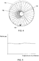
- a full front view of the arrangement is shown in Fig. 4 , where a plurality of turbine blades 102 are mounted on and rotate with a central shaft 106 relative to the annular casing 108.
- the positioning device 100 is mounted towards the distal end of the turbine blade 102, i.e. towards the end closer to the annular casing. As shown in Fig. 3 , the purpose of the positioning device is to hold an optical triangulation sensor 110 in manner that permits it to measure the gap between the distal edge 112 of the turbine blade 102 and the inner surface 104 of the annular casing.
- the gap is an engineered radial spacing that permits rotation of the turbine blade without catching on the annular casing.
- the optical triangulation sensor is a Gap Gun manufactured by Third Dimension Software Limited. It is arranged to emit a planar light beam with intersects with the turbine blade and the inner surface to project a line of light thereon. The line of light exhibits a discontinuity at the radial gap. This discontinuity can be used to measure the size of the gap.
- the camera and laser (and hence the plane of the laser beam) have a known geometric relationship relative to each other. This allows the position of the laser line in the camera image to be converted to a digital representation of the true shape of the visible parts of the blade and the casing (inner surface). Measurements of the gap can then be extracted either automatically or manually from this information.
- the optical triangulation sensor includes an image detector (e.g. CCD or suitable camera). The positioning device 100 is arranged to locate the optical triangulation sensor so that the line of light with the discontinuity lies in the field of view of the image detector.
- the positioning device To locate the optical triangulation sensor in the correct position, the positioning device includes an attachment band 114 which fits around the turbine blade 102.
- the attachment band 114 is shaped to mate with a particular cross-sectional profile of the turbine blade, so that the positioning device can be mounted consistently in a similar position on a plurality of turbine blades.
- the sensor may output a guide beam that assists an operator to move the sensor further from or closer to the casing.
- the attachment band 114 has a frame 116 extending away from it towards the distal end of the turbine blade 102.
- the frame 116 includes a platform 118 for supporting the optical triangulation sensor 110 at an oblique angle relative to the radial direction.
- the platform is a pair of angled finger elements.
- the frame 116 thus supports the optical triangulation sensor 110 at a position that is radially closer to the distal end of the turbine blade than the attachment band 114.
- the attachment band 114 therefore does not interfere with the measurements taken by the optical triangulation sensor 110.
- a housing 120 is mounted on the attachment band 114.
- the housing 120 contains an orientation sensing device (not shown), such as an accelerometer or gyroscope.
- the orientation sensing device comprises a six degree of freedom orientation sensor comprising a plurality of accelerometers and magnetic compasses.
- the housing 120 may also contain a controller, e.g. a microprocessor or the like, that is arranged to operate the optical triangulation sensor 110 and orientation sensing device.
- the optical triangulation sensor 110 may be in communication with the controller via a wired connection 122.
- the housing 120 may further contain a data transmitter (not shown) and communication module for communicating an output of the orientation device and the camera of the optical triangulation sensor to a remote computer, which is arranged to analyse and display the data.
- the data transmitter may be arranged to communicate by any of Ethernet, WiFi, Zigbee® and Bluetooth®.
- the positioning device 100 is mounted on the turbine blade 102 and the optical triangulation sensor 110 mounted thereon as shown in Fig. 3 .
- the turbine blade 102 is then rotated, e.g. manually, relative to the inner surface 104 of the annular casing.
- the controller is arranged to instruct the optical triangulation sensor to capture an image and to detect the orientation of the orientation sensing device that corresponds to the captured image.
- the controller is arranged to perform this process at regular intervals as the turbine blade rotates around the annular casing.
- the captured images and associated orientation data can be transmitted wirelessly from the device to a remote computer for processing. Some processing may be done by the controller, e.g. to speed up the transmission process. In some embodiments all processing may be done locally on the device. Where partial processing is done locally, the intermediate data may be any of camera images, point cloud data (i.e. true digital representation of shape) or other partially processed data.
- the data captured by the optical triangulation sensor can processed to produce a measurement of the radial gap.
- the data from the orientation sensing device can be interpreted as an angular position around the circumference of the annular casing.
- the data can be processing to yield a radial gap profile as shown in Fig. 5 , where the radial gap is plotted as a function of angle around the circumference of the inner surface.
- the graph would be used in conjunction with a tolerance band used to determine pass/fail acceptance criteria for the blade clearance.
- the tolerance band may be represented graphically as a pair of horizontal lines on the graph. The measured data points are required to lie between the horizontal lines in order to meet the tolerance criteria.
- the output data records the radial position of the sensor and angle
Landscapes
- Physics & Mathematics (AREA)
- General Physics & Mathematics (AREA)
- Engineering & Computer Science (AREA)
- Electromagnetism (AREA)
- Mechanical Engineering (AREA)
- General Engineering & Computer Science (AREA)
- Computer Networks & Wireless Communication (AREA)
- Radar, Positioning & Navigation (AREA)
- Remote Sensing (AREA)
- Length Measuring Devices By Optical Means (AREA)
Claims (15)
- Positionierungsvorrichtung (100) zur Lokalisierung eines planaren Lichtstrahls, der von einem optischen Triangulationssensor über den Radialspalt zwischen einem distalen Rand (112) einer Turbinenschaufel (102) und der Innenfläche (104) eines ringförmigen Gehäuses, in dem die Turbinenschaufel rotierbar befestigt ist, emittiert wird, wobei die Positionierungsvorrichtung Folgendes umfasst:eine Befestigungsvorrichtung (114) zum Befestigen auf der Turbinenschaufel, wobei die Befestigungsvorrichtung einen Rahmen (116) zum Tragen eines optischen Triangulationssensors (110) in einer fixen Position im Bezug auf die Befestigungsvorrichtung aufweist; undeine Orientierungsabfühlvorrichtung, die auf der Befestigungsvorrichtung angebracht ist, wobei die Orientierungsabfühlvorrichtung angeordnet ist, um ihre Orientierung hinsichtlich der Richtung, in die die Schwerkraft wirkt, zu detektieren, und dadurch eine Orientierung der Turbinenschaufel abzufühlen, wenn die Befestigungsvorrichtung darauf befestigt ist,wobei die Befestigungsvorrichtung ein geformtes Retentionsprofil aufweist, das angepasst ist, um mit der Turbinenschaufel an einer auf dieser fixen Radialposition zusammenzupassen.
- Positionierungsvorrichtung nach Anspruch 1, wobei der Rahmen mit der Befestigungsvorrichtung einstückig ausgebildet ist.
- Positionierungsvorrichtung nach Anspruch 1 oder 2, wobei der Rahmen einen oder mehrere Eingriffsschenkel umfasst, um den optischen Triangulationssensor derart zu orientieren, um die Durchführung einer Messung des Radialspalts zwischen dem distalen Rand der Turbinenschaufel und der Innenfläche des ringförmigen Gehäuses zu bewirken.
- Positionierungsvorrichtung nach einem der vorangegangenen Ansprüche, wobei die Befestigungsvorrichtung ein Band umfasst, das die Turbinenschaufel umschlingt.
- Positionierungsvorrichtung nach einem der vorangegangenen Ansprüche, umfassend eine Steuerung, die verbindbar ist, um mit dem optischen Triangulationssensor und der Orientierungsabfühlvorrichtung wirksam zu kommunizieren, wobei die Steuerung angeordnet ist, um
ein Bildaufnahmeauslösesignal auszugeben, um zu bewirken, dass der optische Triangulationssensor ein Bild der Linie, die von dem planaren Lichtstrahl projiziert wird, der einen Radialspalt zwischen dem distalen Rand der Turbinenschaufel und der Innenfläche des ringförmigen Gehäuses überspannt, aufzunehmen; und
ein Orientierungsdetektionsauslösesignal auszugeben, um zu bewirken, dass die Orientierungsabfühlvorrichtung eine Orientierung, die dem aufgenommenen Bild entspricht, detektiert. - Positionierungsvorrichtung nach Anspruch 5, wobei die Steuerung angeordnet ist, um das Bildaufnahmeauslösesignal und das Orientierungsdetektionsauslösesignal gleichzeitig auszugeben.
- Positionierungsvorrichtung nach Anspruch 5 oder 6, umfassend einen Speicher zum Speichern des aufgenommenen Bildes.
- Positionierungsvorrichtung nach einem der Ansprüche 5 bis 7, wobei die Steuerung angeordnet ist, um eine Vielzahl von Bildaufnahmeauslösesignalen und Orientierungsdetektionsauslösesignalen nach einem vorbestimmten Zeitplan auszugeben.
- Positionierungsvorrichtung nach einem der vorangegangenen Ansprüche, umfassend einen Sender, der mit einem Fernrechner in drahtloser Kommunikation verbindbar ist.
- Verfahren zum Messen des Radialspalts zwischen einem distalen Rand (112) einer Turbinenschaufel (102) und der Innenfläche (104) eines ringförmigen Gehäuses, in dem die Turbinenschaufel rotierbar befestigt ist, wobei das Verfahren Folgendes umfasst:das Befestigen eines optischen Triangulationssensors (110) in einer fixen Radialposition auf der Turbinenschaufel unter Verwendung einer Positionierungsvorrichtung nach einem der Ansprüche 1 bis 9;das Emittieren eines planaren Lichtstrahls von der optischen Triangulation in Richtung des distalen Randes der Turbinenschaufel, sodass der planare Lichtstrahl die Turbinenschaufel und die Innenfläche des ringförmigen Gehäuses in einer Linie schneidet, die einen Radialspalt zwischen dem distalen Ende der Turbinenschaufel und der Innenfläche des ringförmigen Gehäuses überspannt;das Drehen der Turbinenschaufel in Bezug auf das ringförmige Gehäuse;das Aufnehmen einer Vielzahl von Bildern von der Linie, die den Radialspalt zwischen dem distalen Rand und der Innenfläche des ringförmigen Gehäuses überspannt; unddas Detektieren einer Winkelposition der Turbinenschaufel in dem ringförmigen Gehäuse für jedes aus der Vielzahl von Bildern.
- Verfahren nach Anspruch 10, umfassend das Ausgeben von Daten, die den Radialspalt zwischen der Turbinenschaufel rund um die Innenfläche des ringförmigen Gehäuses in Abhängigkeit von der Winkelposition der Turbinenschaufel in dem ringförmigen Gehäuse darstellen.
- Verfahren nach Anspruch 10 oder 11, umfassend das Bewirken, dass der optische Triangulationssensor eine Reihe von Bildern in einem jeweils identischen Zeitintervall aufnimmt.
- Verfahren nach einem der Ansprüche 10 bis 12, umfassend das Speichern der aufgenommenen Bilder und der Daten, die die detektierte Winkelposition darstellen, auf eine Weise, die für das Herunterladen oder Übertragen auf einen Computer für die nachfolgende Verarbeitung geeignet ist.
- Verfahren nach einem der Ansprüche 10 bis 12, umfassend das Senden der aufgenommenen Bilder und Daten, die die detektierte Winkelposition darstellen, an einen Fernrechner, der angeordnet ist, um diese zu verarbeiten, um die Daten zu erhalten, die den Radialspalt zwischen der Turbinenschaufel um die Innenfläche des ringförmigen Gehäuses in Abhängigkeit von der Winkelposition der Turbinenschaufel in dem ringförmigen Gehäuse darstellen.
- Verfahren nach Anspruch 14, wobei das Senden drahtlos erfolgt.
Applications Claiming Priority (2)
| Application Number | Priority Date | Filing Date | Title |
|---|---|---|---|
| GBGB1401437.7A GB201401437D0 (en) | 2014-01-28 | 2014-01-28 | Positioning device for an optical triangulation sensor |
| PCT/GB2015/050108 WO2015114309A1 (en) | 2014-01-28 | 2015-01-19 | Positioning device for an optical triangulation sensor |
Publications (2)
| Publication Number | Publication Date |
|---|---|
| EP3100266A1 EP3100266A1 (de) | 2016-12-07 |
| EP3100266B1 true EP3100266B1 (de) | 2020-07-08 |
Family
ID=50287691
Family Applications (1)
| Application Number | Title | Priority Date | Filing Date |
|---|---|---|---|
| EP15701387.1A Active EP3100266B1 (de) | 2014-01-28 | 2015-01-19 | Positionierungsvorrichtung für einen optischen triangulationssensor |
Country Status (4)
| Country | Link |
|---|---|
| US (1) | US10209361B2 (de) |
| EP (1) | EP3100266B1 (de) |
| GB (1) | GB201401437D0 (de) |
| WO (1) | WO2015114309A1 (de) |
Cited By (2)
| Publication number | Priority date | Publication date | Assignee | Title |
|---|---|---|---|---|
| IT202100013208A1 (it) | 2021-05-20 | 2022-11-20 | U Sense It S R L | Apparato e metodo per misurare uno spazio e/o un allineamento e/o un angolo di disallineamento tra superfici, segnatamente sulla base di una tecnica di segmentazione semantica di immagini |
| IT202100013196A1 (it) | 2021-05-20 | 2022-11-20 | U Sense It S R L | Apparato e metodo per misurare uno spazio e/o un allineamento e/o un angolo di disallineamento tra superfici, segnatamente sulla base di un modello inferenziale |
Families Citing this family (15)
| Publication number | Priority date | Publication date | Assignee | Title |
|---|---|---|---|---|
| TWI573985B (zh) * | 2016-01-19 | 2017-03-11 | 台達電子工業股份有限公司 | 感測裝置安裝輔助裝置及其輔助調整感測範圍之方法 |
| US10859699B2 (en) * | 2017-07-06 | 2020-12-08 | Raytheon Technologies Corporation | Determining axial location of time of arrival probe |
| DE102017213555A1 (de) | 2017-08-04 | 2019-02-07 | Siemens Aktiengesellschaft | Vorrichtung und Verfahren zum winkelbasierten Lokalisieren einer Position auf einer Oberfläche eines Objekts |
| CN109425313B (zh) * | 2017-08-30 | 2022-12-13 | 上汽通用汽车有限公司 | 手持光泽仪定位装置及手持光泽仪套件 |
| US10920605B2 (en) * | 2017-12-21 | 2021-02-16 | General Electric Company | System and method for measuring eccentricity of turbine shell relative to turbine rotor |
| US20190310373A1 (en) * | 2018-04-10 | 2019-10-10 | Rosemount Aerospace Inc. | Object ranging by coordination of light projection with active pixel rows of multiple cameras |
| US20190376411A1 (en) * | 2018-06-11 | 2019-12-12 | General Electric Company | System and method for turbomachinery blade diagnostics via continuous markings |
| US11156455B2 (en) * | 2018-09-26 | 2021-10-26 | General Electric Company | System and method for measuring clearance gaps between rotating and stationary components of a turbomachine |
| US10690491B1 (en) | 2019-03-27 | 2020-06-23 | Raytheon Technologies Corporation | Standoff fixture for laser inspection |
| US10845189B2 (en) | 2019-03-27 | 2020-11-24 | Raythoen Technologies Corporation | Calibration for laser inspection |
| CN110887446B (zh) * | 2019-11-27 | 2021-02-05 | 中国民航大学 | 采用激光多普勒频移的航空发动机叶尖间隙测量系统 |
| US20220108435A1 (en) * | 2020-10-02 | 2022-04-07 | Baker Hughes Oilfield Operations Llc | Automated turbine blade to shroud gap measurement |
| CN112461128A (zh) * | 2020-11-09 | 2021-03-09 | 哈尔滨工业大学芜湖机器人产业技术研究院 | 一种叶轮焊接模具检测装置及方法 |
| CN113819083A (zh) * | 2021-09-30 | 2021-12-21 | 东风马勒热系统有限公司 | 监测硅油风扇与护风圈间隙值的系统 |
| US11885228B2 (en) * | 2022-02-09 | 2024-01-30 | General Electric Company | System and method for inspecting fan blade tip clearance relative to an abradable fan case |
Family Cites Families (15)
| Publication number | Priority date | Publication date | Assignee | Title |
|---|---|---|---|---|
| US4326804A (en) | 1980-02-11 | 1982-04-27 | General Electric Company | Apparatus and method for optical clearance determination |
| US4541721A (en) * | 1983-03-17 | 1985-09-17 | Perceptron, Inc. | Optical checking apparatus and method of using same |
| JPS61161406A (ja) | 1985-01-11 | 1986-07-22 | Kansai Electric Power Co Inc:The | シールフィンの摩耗測定装置 |
| JPS61161407A (ja) * | 1985-01-11 | 1986-07-22 | Kansai Electric Power Co Inc:The | 微小間隙測定装置 |
| JPH02185602A (ja) | 1989-01-11 | 1990-07-20 | Mitsubishi Heavy Ind Ltd | 動翼先端すき間計測装置 |
| DE29616604U1 (de) | 1996-09-24 | 1996-11-07 | Gottlieb Nestle Gmbh & Co Kg | Markiervorrichtung zur Definition eines Sägeschnittes |
| WO2005073667A1 (en) | 2004-01-27 | 2005-08-11 | Siemens Corporate Research, Inc. | Inductive apparatus and method for measuring compressor blade tip clearance in a gas turbine engine |
| DE102006033461A1 (de) | 2006-07-19 | 2008-01-31 | Siemens Ag | Radialspaltmessung an Turbinen |
| GB0714974D0 (en) * | 2007-07-31 | 2007-09-12 | Third Dimension Software Ltd | Measurement apparatus |
| GB2460248B (en) * | 2008-05-21 | 2011-01-12 | Rolls Royce Plc | Clearance determination device |
| GB2462829B (en) | 2008-08-20 | 2011-02-23 | Rolls Royce Plc | Measurement method |
| GB0919352D0 (en) * | 2009-11-05 | 2009-12-23 | Third Dimension Software Ltd | Optical metrology apparatus and method |
| WO2012091821A1 (en) * | 2010-12-30 | 2012-07-05 | General Electric Company | Apparatus and method for measuring runout |
| US9513117B2 (en) * | 2013-10-02 | 2016-12-06 | Siemens Energy, Inc. | Situ blade mounted tip gap measurement for turbines |
| US9068906B2 (en) * | 2013-10-02 | 2015-06-30 | Siemens Energy, Inc. | Turbine blade-mounted sensor fixture for tip gap measurement |
-
2014
- 2014-01-28 GB GBGB1401437.7A patent/GB201401437D0/en not_active Ceased
-
2015
- 2015-01-19 EP EP15701387.1A patent/EP3100266B1/de active Active
- 2015-01-19 US US15/114,205 patent/US10209361B2/en active Active
- 2015-01-19 WO PCT/GB2015/050108 patent/WO2015114309A1/en active Application Filing
Non-Patent Citations (1)
| Title |
|---|
| None * |
Cited By (2)
| Publication number | Priority date | Publication date | Assignee | Title |
|---|---|---|---|---|
| IT202100013208A1 (it) | 2021-05-20 | 2022-11-20 | U Sense It S R L | Apparato e metodo per misurare uno spazio e/o un allineamento e/o un angolo di disallineamento tra superfici, segnatamente sulla base di una tecnica di segmentazione semantica di immagini |
| IT202100013196A1 (it) | 2021-05-20 | 2022-11-20 | U Sense It S R L | Apparato e metodo per misurare uno spazio e/o un allineamento e/o un angolo di disallineamento tra superfici, segnatamente sulla base di un modello inferenziale |
Also Published As
| Publication number | Publication date |
|---|---|
| EP3100266A1 (de) | 2016-12-07 |
| US20170003393A1 (en) | 2017-01-05 |
| US10209361B2 (en) | 2019-02-19 |
| WO2015114309A1 (en) | 2015-08-06 |
| GB201401437D0 (en) | 2014-03-12 |
Similar Documents
| Publication | Publication Date | Title |
|---|---|---|
| EP3100266B1 (de) | Positionierungsvorrichtung für einen optischen triangulationssensor | |
| US8875409B2 (en) | Coordinate measurement machines with removable accessories | |
| US10866089B2 (en) | Two-camera triangulation scanner with detachable coupling mechanism | |
| US20190079522A1 (en) | Unmanned aerial vehicle having a projector and being tracked by a laser tracker | |
| US9228816B2 (en) | Method of determining a common coordinate system for an articulated arm coordinate measurement machine and a scanner | |
| US9188430B2 (en) | Compensation of a structured light scanner that is tracked in six degrees-of-freedom | |
| US10089415B2 (en) | Three-dimensional coordinate scanner and method of operation | |
| US9267784B2 (en) | Laser line probe having improved high dynamic range | |
| WO2013188026A1 (en) | Coordinate measurement machines with removable accessories | |
| JP7025156B2 (ja) | データ処理装置、データ処理方法およびデータ処理用プログラム | |
| US20100149525A1 (en) | Multi-dimensional measuring system with measuring instrument having 360° angular working range | |
| US11460299B2 (en) | Survey system | |
| CN105102925A (zh) | 三维坐标扫描仪和操作方法 | |
| JP2016015720A (ja) | バーチャルデータ投影方法及び投影装置 | |
| JP2014511480A (ja) | 対象の位置および移動を測定するシステム | |
| CN105068082A (zh) | 一种激光雷达扫描探测方法及装置 | |
| US20150109626A1 (en) | Tire Digitizer | |
| EP3839418A1 (de) | Optischer sensor mit übersichtskamera | |
| EP2836788B1 (de) | Mobile anzeigeeinheit zur anzeige grafischer informationen zur darstellung einer anordnung physischer komponenten | |
| US20180031596A1 (en) | Speed Analyzer | |
| US20220307646A1 (en) | Inclination sensor and data acquisition device | |
| JP2020148700A (ja) | 距離画像センサ、および角度情報取得方法 | |
| Lavelle et al. | A Handheld, Wireless 3D Laser Scanner for Shuttle Tile Inspection |
Legal Events
| Date | Code | Title | Description |
|---|---|---|---|
| PUAI | Public reference made under article 153(3) epc to a published international application that has entered the european phase |
Free format text: ORIGINAL CODE: 0009012 |
|
| STAA | Information on the status of an ep patent application or granted ep patent |
Free format text: STATUS: REQUEST FOR EXAMINATION WAS MADE |
|
| 17P | Request for examination filed |
Effective date: 20160729 |
|
| AK | Designated contracting states |
Kind code of ref document: A1 Designated state(s): AL AT BE BG CH CY CZ DE DK EE ES FI FR GB GR HR HU IE IS IT LI LT LU LV MC MK MT NL NO PL PT RO RS SE SI SK SM TR |
|
| AX | Request for extension of the european patent |
Extension state: BA ME |
|
| DAX | Request for extension of the european patent (deleted) | ||
| REG | Reference to a national code |
Ref country code: DE Ref legal event code: R079 Ref document number: 602015055355 Country of ref document: DE Free format text: PREVIOUS MAIN CLASS: G11B0011140000 Ipc: G01B0011140000 |
|
| GRAP | Despatch of communication of intention to grant a patent |
Free format text: ORIGINAL CODE: EPIDOSNIGR1 |
|
| STAA | Information on the status of an ep patent application or granted ep patent |
Free format text: STATUS: GRANT OF PATENT IS INTENDED |
|
| RIC1 | Information provided on ipc code assigned before grant |
Ipc: G01B 11/30 20060101ALI20200207BHEP Ipc: G01B 11/14 20060101AFI20200207BHEP Ipc: F01D 21/00 20060101ALI20200207BHEP Ipc: G01B 11/26 20060101ALI20200207BHEP |
|
| INTG | Intention to grant announced |
Effective date: 20200306 |
|
| GRAS | Grant fee paid |
Free format text: ORIGINAL CODE: EPIDOSNIGR3 |
|
| GRAA | (expected) grant |
Free format text: ORIGINAL CODE: 0009210 |
|
| STAA | Information on the status of an ep patent application or granted ep patent |
Free format text: STATUS: THE PATENT HAS BEEN GRANTED |
|
| AK | Designated contracting states |
Kind code of ref document: B1 Designated state(s): AL AT BE BG CH CY CZ DE DK EE ES FI FR GB GR HR HU IE IS IT LI LT LU LV MC MK MT NL NO PL PT RO RS SE SI SK SM TR |
|
| REG | Reference to a national code |
Ref country code: AT Ref legal event code: REF Ref document number: 1288922 Country of ref document: AT Kind code of ref document: T Effective date: 20200715 Ref country code: CH Ref legal event code: EP |
|
| REG | Reference to a national code |
Ref country code: DE Ref legal event code: R096 Ref document number: 602015055355 Country of ref document: DE |
|
| REG | Reference to a national code |
Ref country code: IE Ref legal event code: FG4D |
|
| REG | Reference to a national code |
Ref country code: LT Ref legal event code: MG4D |
|
| REG | Reference to a national code |
Ref country code: NL Ref legal event code: MP Effective date: 20200708 |
|
| PG25 | Lapsed in a contracting state [announced via postgrant information from national office to epo] |
Ref country code: HR Free format text: LAPSE BECAUSE OF FAILURE TO SUBMIT A TRANSLATION OF THE DESCRIPTION OR TO PAY THE FEE WITHIN THE PRESCRIBED TIME-LIMIT Effective date: 20200708 Ref country code: ES Free format text: LAPSE BECAUSE OF FAILURE TO SUBMIT A TRANSLATION OF THE DESCRIPTION OR TO PAY THE FEE WITHIN THE PRESCRIBED TIME-LIMIT Effective date: 20200708 Ref country code: BG Free format text: LAPSE BECAUSE OF FAILURE TO SUBMIT A TRANSLATION OF THE DESCRIPTION OR TO PAY THE FEE WITHIN THE PRESCRIBED TIME-LIMIT Effective date: 20201008 Ref country code: SE Free format text: LAPSE BECAUSE OF FAILURE TO SUBMIT A TRANSLATION OF THE DESCRIPTION OR TO PAY THE FEE WITHIN THE PRESCRIBED TIME-LIMIT Effective date: 20200708 Ref country code: GR Free format text: LAPSE BECAUSE OF FAILURE TO SUBMIT A TRANSLATION OF THE DESCRIPTION OR TO PAY THE FEE WITHIN THE PRESCRIBED TIME-LIMIT Effective date: 20201009 Ref country code: NO Free format text: LAPSE BECAUSE OF FAILURE TO SUBMIT A TRANSLATION OF THE DESCRIPTION OR TO PAY THE FEE WITHIN THE PRESCRIBED TIME-LIMIT Effective date: 20201008 Ref country code: PT Free format text: LAPSE BECAUSE OF FAILURE TO SUBMIT A TRANSLATION OF THE DESCRIPTION OR TO PAY THE FEE WITHIN THE PRESCRIBED TIME-LIMIT Effective date: 20201109 Ref country code: LT Free format text: LAPSE BECAUSE OF FAILURE TO SUBMIT A TRANSLATION OF THE DESCRIPTION OR TO PAY THE FEE WITHIN THE PRESCRIBED TIME-LIMIT Effective date: 20200708 Ref country code: FI Free format text: LAPSE BECAUSE OF FAILURE TO SUBMIT A TRANSLATION OF THE DESCRIPTION OR TO PAY THE FEE WITHIN THE PRESCRIBED TIME-LIMIT Effective date: 20200708 |
|
| PG25 | Lapsed in a contracting state [announced via postgrant information from national office to epo] |
Ref country code: IS Free format text: LAPSE BECAUSE OF FAILURE TO SUBMIT A TRANSLATION OF THE DESCRIPTION OR TO PAY THE FEE WITHIN THE PRESCRIBED TIME-LIMIT Effective date: 20201108 Ref country code: LV Free format text: LAPSE BECAUSE OF FAILURE TO SUBMIT A TRANSLATION OF THE DESCRIPTION OR TO PAY THE FEE WITHIN THE PRESCRIBED TIME-LIMIT Effective date: 20200708 Ref country code: RS Free format text: LAPSE BECAUSE OF FAILURE TO SUBMIT A TRANSLATION OF THE DESCRIPTION OR TO PAY THE FEE WITHIN THE PRESCRIBED TIME-LIMIT Effective date: 20200708 Ref country code: PL Free format text: LAPSE BECAUSE OF FAILURE TO SUBMIT A TRANSLATION OF THE DESCRIPTION OR TO PAY THE FEE WITHIN THE PRESCRIBED TIME-LIMIT Effective date: 20200708 |
|
| REG | Reference to a national code |
Ref country code: AT Ref legal event code: UEP Ref document number: 1288922 Country of ref document: AT Kind code of ref document: T Effective date: 20200708 |
|
| PG25 | Lapsed in a contracting state [announced via postgrant information from national office to epo] |
Ref country code: NL Free format text: LAPSE BECAUSE OF FAILURE TO SUBMIT A TRANSLATION OF THE DESCRIPTION OR TO PAY THE FEE WITHIN THE PRESCRIBED TIME-LIMIT Effective date: 20200708 |
|
| REG | Reference to a national code |
Ref country code: DE Ref legal event code: R097 Ref document number: 602015055355 Country of ref document: DE |
|
| PG25 | Lapsed in a contracting state [announced via postgrant information from national office to epo] |
Ref country code: EE Free format text: LAPSE BECAUSE OF FAILURE TO SUBMIT A TRANSLATION OF THE DESCRIPTION OR TO PAY THE FEE WITHIN THE PRESCRIBED TIME-LIMIT Effective date: 20200708 Ref country code: SM Free format text: LAPSE BECAUSE OF FAILURE TO SUBMIT A TRANSLATION OF THE DESCRIPTION OR TO PAY THE FEE WITHIN THE PRESCRIBED TIME-LIMIT Effective date: 20200708 Ref country code: RO Free format text: LAPSE BECAUSE OF FAILURE TO SUBMIT A TRANSLATION OF THE DESCRIPTION OR TO PAY THE FEE WITHIN THE PRESCRIBED TIME-LIMIT Effective date: 20200708 Ref country code: CZ Free format text: LAPSE BECAUSE OF FAILURE TO SUBMIT A TRANSLATION OF THE DESCRIPTION OR TO PAY THE FEE WITHIN THE PRESCRIBED TIME-LIMIT Effective date: 20200708 Ref country code: DK Free format text: LAPSE BECAUSE OF FAILURE TO SUBMIT A TRANSLATION OF THE DESCRIPTION OR TO PAY THE FEE WITHIN THE PRESCRIBED TIME-LIMIT Effective date: 20200708 |
|
| PLBE | No opposition filed within time limit |
Free format text: ORIGINAL CODE: 0009261 |
|
| STAA | Information on the status of an ep patent application or granted ep patent |
Free format text: STATUS: NO OPPOSITION FILED WITHIN TIME LIMIT |
|
| PG25 | Lapsed in a contracting state [announced via postgrant information from national office to epo] |
Ref country code: AL Free format text: LAPSE BECAUSE OF FAILURE TO SUBMIT A TRANSLATION OF THE DESCRIPTION OR TO PAY THE FEE WITHIN THE PRESCRIBED TIME-LIMIT Effective date: 20200708 |
|
| 26N | No opposition filed |
Effective date: 20210409 |
|
| PG25 | Lapsed in a contracting state [announced via postgrant information from national office to epo] |
Ref country code: SK Free format text: LAPSE BECAUSE OF FAILURE TO SUBMIT A TRANSLATION OF THE DESCRIPTION OR TO PAY THE FEE WITHIN THE PRESCRIBED TIME-LIMIT Effective date: 20200708 |
|
| PG25 | Lapsed in a contracting state [announced via postgrant information from national office to epo] |
Ref country code: SI Free format text: LAPSE BECAUSE OF FAILURE TO SUBMIT A TRANSLATION OF THE DESCRIPTION OR TO PAY THE FEE WITHIN THE PRESCRIBED TIME-LIMIT Effective date: 20200708 Ref country code: MC Free format text: LAPSE BECAUSE OF FAILURE TO SUBMIT A TRANSLATION OF THE DESCRIPTION OR TO PAY THE FEE WITHIN THE PRESCRIBED TIME-LIMIT Effective date: 20200708 |
|
| REG | Reference to a national code |
Ref country code: CH Ref legal event code: PL |
|
| PG25 | Lapsed in a contracting state [announced via postgrant information from national office to epo] |
Ref country code: LU Free format text: LAPSE BECAUSE OF NON-PAYMENT OF DUE FEES Effective date: 20210119 |
|
| REG | Reference to a national code |
Ref country code: BE Ref legal event code: MM Effective date: 20210131 |
|
| PG25 | Lapsed in a contracting state [announced via postgrant information from national office to epo] |
Ref country code: LI Free format text: LAPSE BECAUSE OF NON-PAYMENT OF DUE FEES Effective date: 20210131 Ref country code: CH Free format text: LAPSE BECAUSE OF NON-PAYMENT OF DUE FEES Effective date: 20210131 |
|
| PG25 | Lapsed in a contracting state [announced via postgrant information from national office to epo] |
Ref country code: IE Free format text: LAPSE BECAUSE OF NON-PAYMENT OF DUE FEES Effective date: 20210119 |
|
| PG25 | Lapsed in a contracting state [announced via postgrant information from national office to epo] |
Ref country code: BE Free format text: LAPSE BECAUSE OF NON-PAYMENT OF DUE FEES Effective date: 20210131 |
|
| PGFP | Annual fee paid to national office [announced via postgrant information from national office to epo] |
Ref country code: FR Payment date: 20230124 Year of fee payment: 9 Ref country code: AT Payment date: 20230127 Year of fee payment: 9 |
|
| PG25 | Lapsed in a contracting state [announced via postgrant information from national office to epo] |
Ref country code: HU Free format text: LAPSE BECAUSE OF FAILURE TO SUBMIT A TRANSLATION OF THE DESCRIPTION OR TO PAY THE FEE WITHIN THE PRESCRIBED TIME-LIMIT; INVALID AB INITIO Effective date: 20150119 |
|
| PGFP | Annual fee paid to national office [announced via postgrant information from national office to epo] |
Ref country code: IT Payment date: 20230125 Year of fee payment: 9 Ref country code: GB Payment date: 20230120 Year of fee payment: 9 Ref country code: DE Payment date: 20230124 Year of fee payment: 9 |
|
| PG25 | Lapsed in a contracting state [announced via postgrant information from national office to epo] |
Ref country code: CY Free format text: LAPSE BECAUSE OF FAILURE TO SUBMIT A TRANSLATION OF THE DESCRIPTION OR TO PAY THE FEE WITHIN THE PRESCRIBED TIME-LIMIT Effective date: 20200708 |
|
| PGFP | Annual fee paid to national office [announced via postgrant information from national office to epo] |
Ref country code: AT Payment date: 20240123 Year of fee payment: 10 |
|
| PG25 | Lapsed in a contracting state [announced via postgrant information from national office to epo] |
Ref country code: MK Free format text: LAPSE BECAUSE OF FAILURE TO SUBMIT A TRANSLATION OF THE DESCRIPTION OR TO PAY THE FEE WITHIN THE PRESCRIBED TIME-LIMIT Effective date: 20200708 |
|
| PGFP | Annual fee paid to national office [announced via postgrant information from national office to epo] |
Ref country code: DE Payment date: 20240122 Year of fee payment: 10 Ref country code: GB Payment date: 20240122 Year of fee payment: 10 |