EP3100129B1 - Improved relaxation oscillator with low drift and native offset cancellation - Google Patents
Improved relaxation oscillator with low drift and native offset cancellation Download PDFInfo
- Publication number
- EP3100129B1 EP3100129B1 EP15740079.7A EP15740079A EP3100129B1 EP 3100129 B1 EP3100129 B1 EP 3100129B1 EP 15740079 A EP15740079 A EP 15740079A EP 3100129 B1 EP3100129 B1 EP 3100129B1
- Authority
- EP
- European Patent Office
- Prior art keywords
- node
- current
- oscillator
- amplifier
- circuit
- Prior art date
- Legal status (The legal status is an assumption and is not a legal conclusion. Google has not performed a legal analysis and makes no representation as to the accuracy of the status listed.)
- Active
Links
- 230000001976 improved effect Effects 0.000 title description 4
- 230000000694 effects Effects 0.000 description 10
- 239000003990 capacitor Substances 0.000 description 8
- 238000010586 diagram Methods 0.000 description 7
- 238000007599 discharging Methods 0.000 description 6
- 101100462365 Aspergillus niger (strain CBS 513.88 / FGSC A1513) otaA gene Proteins 0.000 description 5
- 230000007774 longterm Effects 0.000 description 5
- 101100462367 Aspergillus niger (strain CBS 513.88 / FGSC A1513) otaB gene Proteins 0.000 description 4
- 230000007704 transition Effects 0.000 description 4
- 101100462369 Aspergillus niger (strain CBS 513.88 / FGSC A1513) otaC gene Proteins 0.000 description 3
- 230000015556 catabolic process Effects 0.000 description 3
- 230000008859 change Effects 0.000 description 3
- 238000006731 degradation reaction Methods 0.000 description 3
- 238000013461 design Methods 0.000 description 3
- 230000036039 immunity Effects 0.000 description 3
- 238000004519 manufacturing process Methods 0.000 description 3
- 238000000034 method Methods 0.000 description 3
- 230000008569 process Effects 0.000 description 3
- 238000012545 processing Methods 0.000 description 2
- 238000004513 sizing Methods 0.000 description 2
- 238000012358 sourcing Methods 0.000 description 2
- 230000032683 aging Effects 0.000 description 1
- 230000000295 complement effect Effects 0.000 description 1
- 239000000470 constituent Substances 0.000 description 1
- 230000008878 coupling Effects 0.000 description 1
- 238000010168 coupling process Methods 0.000 description 1
- 238000005859 coupling reaction Methods 0.000 description 1
- 230000007423 decrease Effects 0.000 description 1
- 230000003247 decreasing effect Effects 0.000 description 1
- 230000007850 degeneration Effects 0.000 description 1
- 238000010141 design making Methods 0.000 description 1
- 238000013100 final test Methods 0.000 description 1
- 230000001939 inductive effect Effects 0.000 description 1
- 230000007246 mechanism Effects 0.000 description 1
- 230000000116 mitigating effect Effects 0.000 description 1
- 238000012986 modification Methods 0.000 description 1
- 230000004048 modification Effects 0.000 description 1
- 230000010355 oscillation Effects 0.000 description 1
- 230000004044 response Effects 0.000 description 1
- 230000000630 rising effect Effects 0.000 description 1
- 230000008054 signal transmission Effects 0.000 description 1
Images


Classifications
-
- H—ELECTRICITY
- H03—ELECTRONIC CIRCUITRY
- H03K—PULSE TECHNIQUE
- H03K4/00—Generating pulses having essentially a finite slope or stepped portions
- H03K4/06—Generating pulses having essentially a finite slope or stepped portions having triangular shape
- H03K4/08—Generating pulses having essentially a finite slope or stepped portions having triangular shape having sawtooth shape
- H03K4/48—Generating pulses having essentially a finite slope or stepped portions having triangular shape having sawtooth shape using as active elements semiconductor devices
- H03K4/50—Generating pulses having essentially a finite slope or stepped portions having triangular shape having sawtooth shape using as active elements semiconductor devices in which a sawtooth voltage is produced across a capacitor
-
- H—ELECTRICITY
- H03—ELECTRONIC CIRCUITRY
- H03K—PULSE TECHNIQUE
- H03K3/00—Circuits for generating electric pulses; Monostable, bistable or multistable circuits
- H03K3/01—Details
- H03K3/011—Modifications of generator to compensate for variations in physical values, e.g. voltage, temperature
-
- H—ELECTRICITY
- H03—ELECTRONIC CIRCUITRY
- H03K—PULSE TECHNIQUE
- H03K3/00—Circuits for generating electric pulses; Monostable, bistable or multistable circuits
- H03K3/02—Generators characterised by the type of circuit or by the means used for producing pulses
- H03K3/023—Generators characterised by the type of circuit or by the means used for producing pulses by the use of differential amplifiers or comparators, with internal or external positive feedback
- H03K3/0231—Astable circuits
-
- H—ELECTRICITY
- H03—ELECTRONIC CIRCUITRY
- H03K—PULSE TECHNIQUE
- H03K5/00—Manipulating of pulses not covered by one of the other main groups of this subclass
- H03K5/003—Changing the DC level
Definitions
- Relaxation oscillator circuits are used for providing clock signals in applications that specify a precise output signal frequency.
- Many relaxation oscillators operate by charging and discharging reactive components and comparing the charged state variable with a preset threshold to provide for state switching of a bi-stable output defining a clock cycle.
- Such circuitry is subject to long-term drift in the output frequency caused by drift of a bandgap or other reference circuit providing the threshold for comparator switching.
- Such circuits often suffer from output frequency drift caused by amplifier gain degradation over time and temperature, as well as comparator offset drift effects and power supply variation.
- US 2011/0140754 relates to an oscillator circuit which increases and reduces signal levels of first and second oscillation signals in a complementary manner in response to a transition of a signal level of a reference clock.
- relaxation oscillator circuitry has low drift and native offset cancellation.
- An amplifier amplifies a first current signal to provide a pulse amplifier output waveform.
- An integrator integrates a second current signal to provide a ramp output waveform.
- a comparator compares the integrator output waveform with a threshold set by the amplifier output waveform to generate an alternating oscillator output used for switching the polarities of the first and second current signals.
- the current signals are generated based on a single input current for matching, with the first and second signals being of generally equal amplitudes and alternating polarities to facilitate native offset cancellation to mitigate oscillator output frequency drift over time and/or supply voltage variations.
- the amplifier and integrator circuits are connected to the same bias node, with the alternate polarity switching of the current signals and current source matching providing native cancellation of offsets using the oscillator's own switching without introduction of additional oscillators or other circuitry.
- the oscillator circuit configuration facilitates the use of resistive divider or other bias voltage circuitry without the cost of high accuracy bandgap circuits and the like.
- the use of current mirror circuitry in certain embodiments facilitates generation of the switched current signals based on a single input current signal, with the current matching being provided by ratiometric circuit design independent of power supply levels for improved power supply rejection ratio (PSRR).
- PSRR power supply rejection ratio
- the output frequency is determined using passive resistive and capacitive components without amplifier offset voltage drift or other active component drift effects.
- the ratiometric scaling cancels offset voltage and amplifier gain degradation effects over time while maintaining low power consumption and small die size ideal for fully integrated precision oscillators.
- oscillator circuitry includes a first amplifier with a feedback resistance for amplifying a first current signal, as well as an integrator circuit with a second amplifier and a feedback capacitance for integrating a second current signal, along with a comparator providing an oscillator output signal alternating between first and second levels based on comparison of the amplifier and integrator outputs.
- the first and second amplifiers have inputs coupled to a single bias voltage, with input offset effects of the individual amplifier circuits being canceled by the switching operation of the oscillator circuit.
- a switchable current source circuit provides the first and second current signals of generally equal amplitudes or levels, and alternates the polarities of the current signals based on transitions of the oscillator output signal from the comparator for self-oscillation.
- the switchable current source circuit may include first and second current sources provided by current mirror circuitry to source first and second currents of a first current value to the first and second amplifiers, as well as further current mirror circuitry to provide third and fourth current sources sinking third and fourth currents of twice the first current value, with switching circuitry configured to selectively connect the third and fourth current sources to the inputs of the first and second amplifiers to effectively reverse the polarity of the currents provided to the amplifier and integrator circuits. This creates a pulse output waveform from the amplifier circuit and a ramp waveform output from the integrator circuit for comparison by the comparator to toggle the oscillator output signal and alternate the state of the switching circuitry.
- a relaxation oscillator circuit 100 for generating an oscillating output voltage VOUT.
- the oscillator 100 includes a pair of operational transconductance amplifier (OTA) comparators 101 and 102 comparing charging voltages of corresponding first and second capacitors C1 and C2 with a precision reference voltage threshold (VREF) from a precision reference source 106, such as a bandgap voltage reference circuit, in order to provide reset (RST) and set (SET) inputs to an RS flip-flop 104.
- FIG. 7 further shows input offset voltages 111 and 112 associated with the comparators 101 and 102, respectively.
- the Q output of the flip-flop 104 provides the oscillator output voltage VOUT, and the primary and inverse flip-flop outputs Q and Q' are used for operating a set of switches S1, S2, S3 and S4 to control the charging and discharging of the capacitors C1 and C2 by selective connection of current sources I1, I2, I3 and I4 in order to provide a closed loop self-oscillating circuit.
- the non-inverting comparator inputs are offset from the precision reference voltage VREF by the respective voltage offsets 111 and 112.
- the inverting input of the first comparator 101 is alternately connected to current source I1 or I3 by alternating operation of switches S1 and S3, and the inverting input of the second comparator 102 is alternately connected to either I2 or I4 via switches S2 and S4.
- the switches S1 and S4 are operated concurrently by the Q' output from the flip-flop 104, and switches S2 and S3 are operated according to the Q output.
- a self-oscillating circuit is provided with an operating frequency determined according to the values of the current sources (I in this example), the capacitances of C1 and C2, as well as the supply voltage VCC, the reference voltage VREF and the offset voltages 111 and 112.
- the oscillator circuit 100 is sensitive with respect to both the supply voltage level VCC, as well as to the reference voltage VREF and the offset voltages 111 and 112. Moreover, the oscillator 100 is susceptible to oscillator frequency variation caused by long-term drift in various components of the circuit. For example, both the offset voltages 111 and 112 and the reference voltage 106 will tend to drift over time due to various aging mechanisms, where these drift effects are generally random. In this regard, standalone bandgap reference circuits 106 may drift by as much a 0.5% in the initial six weeks of operation. Thus, the precision threshold reference provided by the bandgap circuit 106 to the inverting inputs of the comparators 101 and 102 will drift or vary with time, and therefore the circuit 100 of FIG.
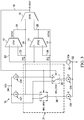
- FIG. 1 shows a relaxation oscillator circuit embodiment 10 using operational transconductance amplifiers 12, 14 and 16 (OTAs), and FIG. 2 further schematically shows the internal offset voltages 44, 46 and 48 of the OTA components of the oscillator 10.
- OTAs operational transconductance amplifiers 12, 14 and 16
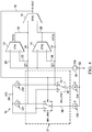
- FIG. 2 further schematically shows the internal offset voltages 44, 46 and 48 of the OTA components of the oscillator 10.
- OTAs operational transconductance amplifiers
- FIG. 2 further schematically shows the internal offset voltages 44, 46 and 48 of the OTA components of the oscillator 10.
- OTA1 operational transconductance amplifiers 12, 14 and 16
- R1 resistor
- This first amplifier circuit 12, R1 receives and amplifies a first current signal I1 received at the inverting input (-) of the first amplifier 12 via a first circuit node 22 to provide a first amplifier output signal VOTA1 at the amplifier output node 24.
- the resistance R1 can be a single resistor component, such as formed in an integrated circuit implementing the oscillator 10, or two or more resistors can be connected in any suitable series and/or parallel configuration to provide a resistance R1 coupled directly or indirectly between the amplifier output node 24 and the first node 22.
- the resistance R1 may be trimmable or otherwise adjustable in certain embodiments.
- the non-inverting (+) input of the first amplifier 12 is coupled with (e.g., connected to) a bias node 20 whose voltage is established by a bias voltage source 30 (VCM) coupled between the bias node 20 and a ground or other constant voltage node 32.
- VCM bias voltage source 30
- the oscillator circuit 10 further includes an integrator circuit formed by a second amplifier 14 (e.g., OTA 2) with a non-inverting input coupled with the bias node 20 and an inverting input coupled with a second circuit node 26, along with a feedback capacitance C1 coupled between the second node 26 and a second amplifier output node 28 to form an inverting integrator circuit.
- the capacitance C1 can be any suitable configuration of one or more capacitors in suitable series and/or parallel interconnections to provide the capacitance C1. Also, the capacitance C1 can be trimmable or adjustable in certain embodiments.
- the integrator circuit 14, C1 receives and integrates a second current signal 12 received at the second node 26 to provide an integrator output signal VOTA2 as a ramp waveform at the output node 28.
- the third amplifier 16 (OTA3) is used as a comparator having a first (+) input receiving the first amplifier output signal VOTA1 at the node 24, as well as a second (-) input coupled to the node 28 to receive the second amplifier output signal VOTA2.
- the comparator 16 includes an output coupled with an output node 18 providing an oscillator output signal VOUT.
- the oscillator output signal at node 18 is at a first level (e.g., low in this example) when the first amplifier output at node 24 is less than the second amplifier output at node 28, and the output signal VOUT is at a different second level (e.g., high) when the output of the first amplifier at node 24 is greater than the second amplifier output at node 28.
- the oscillator output signal VOUT is provided as a switching control signal to a switching circuit 31 including transistors MN1, MN2, MN3 and MN4 which operates in a first state when the oscillator output signal VOUT at node 18 is the first level (e.g., low), and in a second state when VOUT is at the second level (e.g., high). While shown as using N-channel MOSFET switches MN1, MN2, MN3 and MN4, other types and configurations of switches can be used in different embodiments.
- the switching circuit 31 and four matched current sources CS1, CS2, CS3 and CS4 together provide a switchable current source circuit operative in the first state to source a positive first current signal I1 to the first circuit node 22 having a first current value indicated in the drawings as "I", and to also source a positive second current signal I2 of the same value I to the second node 26.
- the switchable current source circuit sinks a negative first current signal I1 having a value I from the node 22 and also sinks a negative second current signal I2 having a value I from the second node 26.
- the first and second current sources CS1 and CS2 are matched to one another to provide substantially equal currents of value I to the first and second nodes 22 and 26, respectively, and likewise the third and fourth current sources CS3 and CS4 are matched to one another to sink generally equal currents of value 2I from the respective first and second nodes 22 and 26 when connected by the switching circuit 31 in the second state.
- operation of the switching circuit 31 according to the state of the output signal VOUT causes the oscillator circuit 10 to be self-oscillating.
- the first amplifier 12 amplifies the alternatively sourcing and sinking current signal I1 from the first node 22 to provide the first amplifier output signal VOTA1 as a pulse waveform having alternating first and second levels as the voltage across the resistance R1 transitions above and below the bias voltage level VCM at the bias node 20.
- the integrator amplifier 14 integrates the second current signal I2 to provide the second amplifier output signal VOTA2 as a ramp waveform having alternating negative and positive slopes. This, in turn, causes the comparator amplifier 16 to provide an alternating output having a low level when the ramp waveform from the integrator amplifier 14 is greater than the pulse waveform from the first amplifier 12 and vice versa.
- the oscillating frequency of the circuit 10 is primarily determined by the passive components R1 and C1.
- the current sources CS1-CS4 are matched with respect to one another, the operating frequency of the oscillator circuit 10 is largely independent of the supply voltage VCC.
- the offset voltages 44 (VOFF1), 46 (VOFF2) and 48 (VOFF3) associated with the OTAs 12, 14 and 16 do not affect the oscillating frequency at the output node 18.
- the geometric matching of the current signals I1 and I2 yields an operating frequency primarily determined by the physical dimensions of the passive components R1 and C1, thereby mitigating or avoiding any frequency drift due to performance (e.g., gain "gm”) degeneration or drift of the amplifiers 12, 14 and 16.
- this drift immunity advantageously allows the use of a low-cost bias voltage source 30, which can be implemented in certain embodiments as a simple resistive divider circuit providing the voltage VCM to the bias node 20 based on the supply voltage VCC, as shown in FIG. 6 below.
- a low-cost bias voltage source 30 which can be implemented in certain embodiments as a simple resistive divider circuit providing the voltage VCM to the bias node 20 based on the supply voltage VCC, as shown in FIG. 6 below.
- the cost and complexity of a bandgap or other precision reference voltage can be avoided without sacrificing stable and accurate oscillator circuit performance.
- the oscillator circuitry 10 can be fabricated in any suitable CMOS process and can be easily integrated with other circuits in an IC with minimal cost and complexity, and provides enhanced frequency stability over supply voltage variation (good power supply rejection ratio PSRR) for long-term frequency stability.
- the passive components R1 and C1 can be fabricated using low temperature coefficient fabrication processing steps, with the resistor R1 being formed for a designed value of 21.8 k ⁇ , and the capacitance C1 is provided as a trimmable capacitor bank with an untrimmed value of 92 pF for a ratio 1/4R1C1 to yield an oscillating frequency of approximately 1.25 MHz, which can be trimmed to 1 MHz.
- the value for the current "I" is 10 ⁇ A as a designed value.
- the oscillator frequency will be independent of the absolute value of the current "I".
- the switching circuit 31 can be fabricated using any suitable form of switching devices, where the example circuit transistors MN1-MN4 are N-channel MOSFET transistors. As shown in FIGS. 3 and 4 , the transistors MN1 and MN3 are used for selectively coupling the current source CS3 with the first circuit node 22 or with the supply voltage node 34 (VCC), and the transistors MN2 and MN4 operate to selectively couple the current source CS4 with the second circuit node 26 or with the supply node 34.
- VCC supply voltage node 34
- the switching transistors MN1 and MN2 in this example are operated according to the signal VOUT from the node 18, while the transistors MN3 and MN4 are operated according to the inverse of VOUT provided on a circuit node 42 from the output of an inverter 40 ( FIGS. 1 and 2 ).
- the switches MN1 and MN3 effectively provide a single pole double throw switch, as do the transistors MN2 and MN4 as schematically shown in FIGS. 3 and 4 .
- FIGS. 3 and 4 illustrate operation of the oscillator circuit 10 in the two output states, where FIG. 3 shows the switching circuit 31 in the first state for a low output voltage VOUT at the node 18.
- a positive first current signal I1 I is provided from the source CS1 to the first node 22 (left to right in the drawing), and the lower current source CS3 conducts its current of a value 2I from VCC through a third circuit node 36 to the constant voltage node 32 (e.g., ground).
- the inverting amplifier 12 amplifies the first current signal I1 to provide a low output voltage at the node 24 as a first input to the comparator 16.
- the integrator circuit 14, C1 inverting integrator configuration
- the comparator 16 in the example first state provides a low voltage VOUT at the output node 18 until the downward ramp signal VOTA2 decreases below the low output level of VOTA1.
- the fourth node 38 is connected to the second node 26 to connect CS4 so that CS2 and CS4 interact in aggregate to sink current from the second node 26 such that the second current signal I2 is equal to -I (right to left in the drawing).
- the first amplifier 12 provides a high output signal to the node 24 due to its inverting amplifier configuration, while the integrator circuit 14, C1 integrates the sinking current signal which discharges C1 to provide an upward ramp signal output waveform at node 28.
- the comparator 16 in this situation provides a high oscillator output voltage VOUT at the node 18 until the rising ramp signal VOTA2 exceeds the high pulse signal output on the node 24.
- the circuit configuration of the amplifier 12, R1, the integrator 14, C1 and the comparator 16 provides an alternating pulse signal at the node 24 as a threshold for comparison by the comparator 16 with the triangular integrator output signal at the node 28.
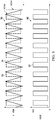
- FIG. 5 shows graphs 50 and 60, in which the graph 50 shows the first amplifier output signal VOTA1 as waveform 52 having a generally square pulse waveform shape, as well as the integrator output waveform VOTA2 shown as a triangular waveform 54. Also, the graph 60 shows the oscillator output voltage waveform 62 (VOUT) having an alternating pulse waveform shape providing the output of the oscillator circuit 10.
- FIG. 5 also shows one example bias voltage level VCM provided by the bias voltage source 30, in this case approximately midway between the high and low states of the first amplifier output pulse waveform 52 (VOTA1).
- FIG. 6 shows one embodiment of the switchable current source circuit which provides matched first and second current signals I1 and I2 of alternating polarity according to the oscillator output signal VOUT using current mirror circuitry based on a single input current signal having a value I in this example from a current source CS5.
- the current from CS5 conducts through an NMOS transistor MN5 forming a current mirror circuit with NMOS transistors MN6, MN7, MN8 and MN9.
- the transistors MN8 and MN9 are twice the size of MN5 to provide the current sources CS3 and CS4 conducting generally equal currents of a value 2I respectively between the corresponding third and fourth nodes 36, 38 and the constant voltage ground node 32.
- the currents through MN6 and MN7 in this case, as well as MP1 have a value of "I" due to the matched sizing of these transistors with MN5.
- the current I is mirrored through MN7 to a low voltage cascaded current source MP2 and MP3, which is subsequently mirrored to current sources formed by MP4 and MP5, MP6 and MP7.
- the first current source CS1 is formed by PMOS transistors MP4 and MP5
- the second current source CS2 is formed by PMOS transistors MP6 and MP7.
- the transistors MN1-MN4 of the switching circuit 31 are also shown, with the inverter 40 providing the control signals for operating MN3 and MN4 via node 42.
- the current signals I1 and I2 are provided to the first and second circuit nodes 22 and 26, respectively, having generally equal values of alternating polarities, where the actual absolute values of these currents "I" can vary without changing the oscillator output frequency.
- the matching between the current sources CS1 and CS2 is set by the relative sizes of the constituent transistors in the current mirror circuitry, and the same is true of the matching of the transistors forming CS3 and CS4.
- this matching is easily achieved through fabrication processing by controlling the sizes and areas of the various circuit components, and the matching will not significantly change or drift over time or temperature or power supply level.
- the matching of the first and second current signals I1 and I2 will not drift over time, and thus will not cause any oscillator circuit output frequency drift.
- the matching of the current signals I1 and I2 is largely independent of supply voltage, whereby the oscillator output frequency has good power supply rejection and will not drift or change over time or at different supply levels.
- the oscillator circuit 10 is a significant advance over the design 100 of FIG. 7 , with significantly improved oscillator frequency stability over time.
- the bias voltage supply 30 provides a common mode output signal VCM on the bias node 20 using a resistive voltage divider formed by resistors R2 and R3 connected between VCC and ground to derive the common mode bias voltage VCM from the supply voltage VCC.
- Connection of the bias voltage source 30 to both the non-inverting inputs of the first amplifier 12 and the integrator amplifier 14 provides unitary biasing of the OTAs 12 and 14, with the native or built-in offset voltage cancellation aspects of the design making the oscillator output frequency largely independent of the biasing voltage level VCM and of any changes in the OTA bias voltages 44, 46 and 48 of OTA1-OTA3.
- the circuit frequency stability is not dictated by the exact level VCM provided at the bias node 20 or offset drift effects associated with the active circuits 12, 14 and 16, and a low-cost (e.g., resistive divider) circuit 30 can be used since the circuit stability does not necessitate the use of a higher cost precision voltage source (e.g., bandgap circuit) as in the case of FIG. 7 .
- the relaxation oscillator 10 thus provides native or built-in in offset voltage cancellation, and mitigates or avoids the need for an internal voltage reference to enhance its immunity with respect to degradation of the active amplifier components 12, 14 and 16 over time, and also provides immunity with respect to power supply voltage variations.
- the offset voltages of the OTAs are naturally cancelled during switching operation of the oscillator without external offset cancellation using self-switching operation of the oscillator circuit without external offset cancellation clocks or circuits as detailed further below.
- the oscillator circuit 10 can be implemented on a commercial CMOS process and a PSRR of this circuit is expected to be 0.25%/V. Also, the relaxation oscillator 10 is expected to have a frequency drift less than 0.5% over a 100-year operating time at body core temperature.
- the relaxation oscillator 10 employs OTAs 12, 14 and 16, although voltage amplifiers and comparators (e.g., op amps) can be used in other embodiments.
- OTA1 12 is used for generating the square waveform by multiplying either current I1 or I3-I1 with the resistance of R1, and the resulting square pulse waveform 52 ( FIG. 5 ) serves as the threshold voltage for the output comparator OTA3 16.
- OTA2 14 is used for generating the triangular waveform 54 (for comparison to the pulse threshold) by integrating a fixed current from either current source I2 or I4-I2 over the capacitance C1.
- the non-inverting inputs of both OTA1 and OTA2 are connected together to the common mode bias voltage generator 30 at node 20 to ensure that the OTAs 12 and 14 each have the sufficient headroom for their output swings.
- the current sources CS1 and CS2 as well as CS3 and CS4 are matched with each other respectively, with CS3 and CS4 individually providing twice the currents of I1 and I2.
- I1 and I2 flow into OTA1 and OTA2, with I2 charging the capacitance C1, where the charging time Ton of each cycle is given by the following equations (2) and (3):
- I 2 Ton / C 1 + VOFF 2 2 ⁇ I 1 R 1 + VOFF 1 + VOFF 3
- Ton C 1 2 I 1 R 1 + VOFF 1 + VOFF 3 ⁇ VOFF 2 / I 2.
- OTA3 16 operates as a comparator which compares the triangular waveform 54 with the square wave 52 and changes the state of the switching circuit 31 accordingly.
- the oscillator frequency f is primarily determined by the draw sizes of R1 and C1 and is independent of the supply voltage VCC as well as the model parameters of the active components 12, 14 and 16.
- the above equations (3) and (5)-(7) show the native cancellation of the OTA offset voltages 44, 46 and 48 based on the matching of the current sources CS1-CS4 through ratiometric sizing in the current mirror circuitry (e.g., FIG. 6 ). Since the draw sizes of the components do not change over time, this matching is therefore naturally drift-resistant.
- a low-voltage cascode current mirror architecture may be employed in certain embodiments to achieve a less than 0.5% frequency drift over approximately 100 years operating lifetime.
- the initial accuracy of the oscillating frequency can be further improved by adjusting the sizes of the resistor R1 and/or capacitor C1 at the final test stage to compensate for any process variations, e.g., by fabricating one or both of R1 and/or C1 as trimmable or adjustable components or groups of components in a fabricated integrated circuit. Also, providing OTAs having total delay times of more than approximately 5 orders of magnitude less than the clock cycle time Ton + Toff can effectively ensure that and variation of the OTA total delay time does not significantly impact the accuracy of the relaxation oscillator 10. Also, any temperature drift can be controlled primarily by fabrication of low thermal coefficient passive components R1 and C1.
Landscapes
- Physics & Mathematics (AREA)
- Nonlinear Science (AREA)
- Inductance-Capacitance Distribution Constants And Capacitance-Resistance Oscillators (AREA)
- Amplifiers (AREA)
Description
- Relaxation oscillator circuits are used for providing clock signals in applications that specify a precise output signal frequency. Many relaxation oscillators operate by charging and discharging reactive components and comparing the charged state variable with a preset threshold to provide for state switching of a bi-stable output defining a clock cycle. Such circuitry, however, is subject to long-term drift in the output frequency caused by drift of a bandgap or other reference circuit providing the threshold for comparator switching. Moreover, such circuits often suffer from output frequency drift caused by amplifier gain degradation over time and temperature, as well as comparator offset drift effects and power supply variation.
US 2011/0140754 relates to an oscillator circuit which increases and reduces signal levels of first and second oscillation signals in a complementary manner in response to a transition of a signal level of a reference clock. - In described examples, relaxation oscillator circuitry has low drift and native offset cancellation. An amplifier amplifies a first current signal to provide a pulse amplifier output waveform. An integrator integrates a second current signal to provide a ramp output waveform. A comparator compares the integrator output waveform with a threshold set by the amplifier output waveform to generate an alternating oscillator output used for switching the polarities of the first and second current signals. The current signals are generated based on a single input current for matching, with the first and second signals being of generally equal amplitudes and alternating polarities to facilitate native offset cancellation to mitigate oscillator output frequency drift over time and/or supply voltage variations. Moreover, the amplifier and integrator circuits are connected to the same bias node, with the alternate polarity switching of the current signals and current source matching providing native cancellation of offsets using the oscillator's own switching without introduction of additional oscillators or other circuitry. The oscillator circuit configuration facilitates the use of resistive divider or other bias voltage circuitry without the cost of high accuracy bandgap circuits and the like. The use of current mirror circuitry in certain embodiments facilitates generation of the switched current signals based on a single input current signal, with the current matching being provided by ratiometric circuit design independent of power supply levels for improved power supply rejection ratio (PSRR). Also, the output frequency is determined using passive resistive and capacitive components without amplifier offset voltage drift or other active component drift effects. Thus, the ratiometric scaling cancels offset voltage and amplifier gain degradation effects over time while maintaining low power consumption and small die size ideal for fully integrated precision oscillators.
- In further described examples, oscillator circuitry includes a first amplifier with a feedback resistance for amplifying a first current signal, as well as an integrator circuit with a second amplifier and a feedback capacitance for integrating a second current signal, along with a comparator providing an oscillator output signal alternating between first and second levels based on comparison of the amplifier and integrator outputs. The first and second amplifiers have inputs coupled to a single bias voltage, with input offset effects of the individual amplifier circuits being canceled by the switching operation of the oscillator circuit. A switchable current source circuit provides the first and second current signals of generally equal amplitudes or levels, and alternates the polarities of the current signals based on transitions of the oscillator output signal from the comparator for self-oscillation. The switchable current source circuit may include first and second current sources provided by current mirror circuitry to source first and second currents of a first current value to the first and second amplifiers, as well as further current mirror circuitry to provide third and fourth current sources sinking third and fourth currents of twice the first current value, with switching circuitry configured to selectively connect the third and fourth current sources to the inputs of the first and second amplifiers to effectively reverse the polarity of the currents provided to the amplifier and integrator circuits. This creates a pulse output waveform from the amplifier circuit and a ramp waveform output from the integrator circuit for comparison by the comparator to toggle the oscillator output signal and alternate the state of the switching circuitry.
-
-
FIG. 1 is a schematic diagram of a relaxation oscillator circuit embodiment with amplifier, integrator and comparator circuits using operational transconductance amplifiers, matched current sources and a switching circuit for generating an alternating oscillator output signal. -
FIG. 2 is a schematic diagram of the oscillator circuit ofFIG. 1 showing input offset voltages of the transconductance amplifiers. -
FIG. 3 is a schematic diagram showing operation of the oscillator circuit ofFIGS. 1 and2 in a first state with the current sources and switching circuit sourcing equal positive current signals to the amplifier and integrator to charge an integrator capacitor to provide a decreasing ramp signal and a low threshold signal as inputs to the comparator. -
FIG. 4 is a schematic diagram showing operation of the oscillator circuit ofFIGS. 1-3 in a second state with the current sources and switching circuit sinking equal negative current signals from the amplifier and integrator to discharge the capacitor to provide an increasing ramp signal and a high threshold signal as comparator inputs. -
FIG. 5 is a waveform diagram of alternating output waveforms of the amplifier, integrator and comparator in the oscillator circuit ofFIGS. 1-4 . -
FIG. 6 is a schematic diagram of a switchable current source circuit embodiment providing matched first and second current signals of alternating polarity according to the oscillator output signal using current mirror circuitry based on a single input current signal. -
FIG. 7 is a schematic diagram showing a relaxation oscillator circuit using a precision reference voltage. - Referring initially to
FIG. 7 , arelaxation oscillator circuit 100 is shown for generating an oscillating output voltage VOUT. Theoscillator 100 includes a pair of operational transconductance amplifier (OTA)comparators precision reference source 106, such as a bandgap voltage reference circuit, in order to provide reset (RST) and set (SET) inputs to an RS flip-flop 104.FIG. 7 further showsinput offset voltages comparators flop 104 provides the oscillator output voltage VOUT, and the primary and inverse flip-flop outputs Q and Q' are used for operating a set of switches S1, S2, S3 and S4 to control the charging and discharging of the capacitors C1 and C2 by selective connection of current sources I1, I2, I3 and I4 in order to provide a closed loop self-oscillating circuit. In thiscircuit 100, the non-inverting comparator inputs are offset from the precision reference voltage VREF by therespective voltage offsets first comparator 101 is alternately connected to current source I1 or I3 by alternating operation of switches S1 and S3, and the inverting input of thesecond comparator 102 is alternately connected to either I2 or I4 via switches S2 and S4. Moreover, the switches S1 and S4 are operated concurrently by the Q' output from the flip-flop 104, and switches S2 and S3 are operated according to the Q output. In this manner, a self-oscillating circuit is provided with an operating frequency determined according to the values of the current sources (I in this example), the capacitances of C1 and C2, as well as the supply voltage VCC, the reference voltage VREF and theoffset voltages oscillator circuit 100 is described by the following equation (1):
- As shown in the above equation (1), the
oscillator circuit 100 is sensitive with respect to both the supply voltage level VCC, as well as to the reference voltage VREF and theoffset voltages oscillator 100 is susceptible to oscillator frequency variation caused by long-term drift in various components of the circuit. For example, both theoffset voltages reference voltage 106 will tend to drift over time due to various aging mechanisms, where these drift effects are generally random. In this regard, standalonebandgap reference circuits 106 may drift by as much a 0.5% in the initial six weeks of operation. Thus, the precision threshold reference provided by thebandgap circuit 106 to the inverting inputs of thecomparators circuit 100 ofFIG. 7 is subject to potentially significant oscillator frequency variation or drift over time. Also, drift effects in thecomparator offset voltages oscillator 100 ofFIG. 7 can be addressed in some measure by the use of aprecision reference 106, this increases product cost and does not immunize the circuit from long-term drift effects. This long-term frequency drift posts a challenge for using this type of relaxation oscillator design in applications such as inductive-coupled power and signal transmission circuits for implanted electronic devices, due to their expected long service time and high risk of replacement once in service. - Referring now to
FIGS. 1 and2 ,FIG. 1 shows a relaxationoscillator circuit embodiment 10 usingoperational transconductance amplifiers FIG. 2 further schematically shows theinternal offset voltages oscillator 10. Although shown in certain embodiments using OTAs, other forms of amplifiers can be used for one, some or all of thecomponents oscillator circuit embodiment 10 includes a first amplifier circuit formed by the first amplifier 12 (OTA1) and a resistor R1 connected in a feedback path of theamplifier 12 to form an inverting amplifier configuration. Thisfirst amplifier circuit 12, R1 receives and amplifies a first current signal I1 received at the inverting input (-) of thefirst amplifier 12 via afirst circuit node 22 to provide a first amplifier output signal VOTA1 at theamplifier output node 24. The resistance R1 can be a single resistor component, such as formed in an integrated circuit implementing theoscillator 10, or two or more resistors can be connected in any suitable series and/or parallel configuration to provide a resistance R1 coupled directly or indirectly between theamplifier output node 24 and thefirst node 22. Moreover, the resistance R1 may be trimmable or otherwise adjustable in certain embodiments. The non-inverting (+) input of thefirst amplifier 12 is coupled with (e.g., connected to) abias node 20 whose voltage is established by a bias voltage source 30 (VCM) coupled between thebias node 20 and a ground or otherconstant voltage node 32. - The
oscillator circuit 10 further includes an integrator circuit formed by a second amplifier 14 (e.g., OTA 2) with a non-inverting input coupled with thebias node 20 and an inverting input coupled with asecond circuit node 26, along with a feedback capacitance C1 coupled between thesecond node 26 and a secondamplifier output node 28 to form an inverting integrator circuit. The capacitance C1 can be any suitable configuration of one or more capacitors in suitable series and/or parallel interconnections to provide the capacitance C1. Also, the capacitance C1 can be trimmable or adjustable in certain embodiments. In operation, theintegrator circuit 14, C1 receives and integrates a secondcurrent signal 12 received at thesecond node 26 to provide an integrator output signal VOTA2 as a ramp waveform at theoutput node 28. - The third amplifier 16 (OTA3) is used as a comparator having a first (+) input receiving the first amplifier output signal VOTA1 at the
node 24, as well as a second (-) input coupled to thenode 28 to receive the second amplifier output signal VOTA2. Thecomparator 16 includes an output coupled with anoutput node 18 providing an oscillator output signal VOUT. In particular, the oscillator output signal atnode 18 is at a first level (e.g., low in this example) when the first amplifier output atnode 24 is less than the second amplifier output atnode 28, and the output signal VOUT is at a different second level (e.g., high) when the output of the first amplifier atnode 24 is greater than the second amplifier output atnode 28. - The oscillator output signal VOUT is provided as a switching control signal to a
switching circuit 31 including transistors MN1, MN2, MN3 and MN4 which operates in a first state when the oscillator output signal VOUT atnode 18 is the first level (e.g., low), and in a second state when VOUT is at the second level (e.g., high). While shown as using N-channel MOSFET switches MN1, MN2, MN3 and MN4, other types and configurations of switches can be used in different embodiments. Theswitching circuit 31 and four matched current sources CS1, CS2, CS3 and CS4 together provide a switchable current source circuit operative in the first state to source a positive first current signal I1 to thefirst circuit node 22 having a first current value indicated in the drawings as "I", and to also source a positive second current signal I2 of the same value I to thesecond node 26. When the switchingcircuit 31 is instead in the second state according to the output signal VOUT (e.g., when VOUT is high in this example), the switchable current source circuit sinks a negative first current signal I1 having a value I from thenode 22 and also sinks a negative second current signal I2 having a value I from thesecond node 26. - As discussed further below, the first and second current sources CS1 and CS2 are matched to one another to provide substantially equal currents of value I to the first and
second nodes second nodes circuit 31 in the second state. Moreover, operation of the switchingcircuit 31 according to the state of the output signal VOUT causes theoscillator circuit 10 to be self-oscillating. As a result, thefirst amplifier 12 amplifies the alternatively sourcing and sinking current signal I1 from thefirst node 22 to provide the first amplifier output signal VOTA1 as a pulse waveform having alternating first and second levels as the voltage across the resistance R1 transitions above and below the bias voltage level VCM at thebias node 20. Moreover, theintegrator amplifier 14 integrates the second current signal I2 to provide the second amplifier output signal VOTA2 as a ramp waveform having alternating negative and positive slopes. This, in turn, causes thecomparator amplifier 16 to provide an alternating output having a low level when the ramp waveform from theintegrator amplifier 14 is greater than the pulse waveform from thefirst amplifier 12 and vice versa. - As the integrator signal waveform VOTA2 has a rise time and fall time dictated largely by the amplitude of the current signal I2 and the capacitance of C1, and since the pulse waveform VOTA1 has an amplitude dictated primarily by the current signal I1 and the resistance R1, the oscillating frequency of the
circuit 10 is primarily determined by the passive components R1 and C1. Moreover, since the current sources CS1-CS4 are matched with respect to one another, the operating frequency of theoscillator circuit 10 is largely independent of the supply voltage VCC. Furthermore, unlike theoscillator 100 ofFIG. 7 , theoscillator 10 inFIGS. 1 and2 has an operating oscillator frequency independent of the offsetvoltages amplifiers FIG. 2 , the offset voltages 44 (VOFF1), 46 (VOFF2) and 48 (VOFF3) associated with the OTAs 12, 14 and 16 do not affect the oscillating frequency at theoutput node 18. Also, introducing a local reference voltage which is generated from a copy of the charging and discharging currents of C1, the geometric matching of the current signals I1 and I2 yields an operating frequency primarily determined by the physical dimensions of the passive components R1 and C1, thereby mitigating or avoiding any frequency drift due to performance (e.g., gain "gm") degeneration or drift of theamplifiers - Moreover, this drift immunity advantageously allows the use of a low-cost
bias voltage source 30, which can be implemented in certain embodiments as a simple resistive divider circuit providing the voltage VCM to thebias node 20 based on the supply voltage VCC, as shown inFIG. 6 below. Thus, the cost and complexity of a bandgap or other precision reference voltage can be avoided without sacrificing stable and accurate oscillator circuit performance. Moreover, theoscillator circuitry 10 can be fabricated in any suitable CMOS process and can be easily integrated with other circuits in an IC with minimal cost and complexity, and provides enhanced frequency stability over supply voltage variation (good power supply rejection ratio PSRR) for long-term frequency stability. In one non-limiting example, for instance, the passive components R1 and C1 can be fabricated using low temperature coefficient fabrication processing steps, with the resistor R1 being formed for a designed value of 21.8 kΩ, and the capacitance C1 is provided as a trimmable capacitor bank with an untrimmed value of 92 pF for aratio 1/4R1C1 to yield an oscillating frequency of approximately 1.25 MHz, which can be trimmed to 1 MHz. Moreover, in one embodiment, the value for the current "I" is 10 µA as a designed value. However, by the matching of the current sources CS1-CS4 and the offset canceling circuit configuration, the oscillator frequency will be independent of the absolute value of the current "I". - Referring also to
FIGS. 3-6 , the switchingcircuit 31 can be fabricated using any suitable form of switching devices, where the example circuit transistors MN1-MN4 are N-channel MOSFET transistors. As shown inFIGS. 3 and4 , the transistors MN1 and MN3 are used for selectively coupling the current source CS3 with thefirst circuit node 22 or with the supply voltage node 34 (VCC), and the transistors MN2 and MN4 operate to selectively couple the current source CS4 with thesecond circuit node 26 or with thesupply node 34. The switching transistors MN1 and MN2 in this example are operated according to the signal VOUT from thenode 18, while the transistors MN3 and MN4 are operated according to the inverse of VOUT provided on acircuit node 42 from the output of an inverter 40 (FIGS. 1 and2 ). In this manner, the switches MN1 and MN3 effectively provide a single pole double throw switch, as do the transistors MN2 and MN4 as schematically shown inFIGS. 3 and4 . -
FIGS. 3 and4 illustrate operation of theoscillator circuit 10 in the two output states, whereFIG. 3 shows the switchingcircuit 31 in the first state for a low output voltage VOUT at thenode 18. In this condition, a positive first current signal I1 = I is provided from the source CS1 to the first node 22 (left to right in the drawing), and the lower current source CS3 conducts its current of a value 2I from VCC through athird circuit node 36 to the constant voltage node 32 (e.g., ground). The invertingamplifier 12 amplifies the first current signal I1 to provide a low output voltage at thenode 24 as a first input to thecomparator 16. The switchingcircuit 31 in this state also connects CS2 to provide a positive second current signal I2 = I (left to right in the drawing) to thesecond node 26 to charge the capacitance C1 while connecting the fourth current source CS4 to conduct its current (21) from VCC through afourth circuit node 38 toground 32. In this first state, theintegrator circuit 14, C1 (inverting integrator configuration) integrates thecurrent signal 12 from CS2 in order to provide a downward-sloped ramp signal to the second input of thecomparator 16 atnode 28. Thecomparator 16 in the example first state provides a low voltage VOUT at theoutput node 18 until the downward ramp signal VOTA2 decreases below the low output level of VOTA1. - As shown in
FIG. 4 , when that transition occurs, the output voltage atnode 18 goes high causing the switchingcircuit 31 to enter the second state. In this condition, the switchingcircuit 31 connects thethird node 36 with thefirst node 22, with CS3 conducting 21 from thenode 22 to theground node 32 while CS1 conducts I from thesupply node 34 to thefirst node 22, yielding a sinking first current signal I1 = -I (right to left in the drawing). Also, thefourth node 38 is connected to thesecond node 26 to connect CS4 so that CS2 and CS4 interact in aggregate to sink current from thesecond node 26 such that the second current signal I2 is equal to -I (right to left in the drawing). In this second switching state, thefirst amplifier 12 provides a high output signal to thenode 24 due to its inverting amplifier configuration, while theintegrator circuit 14, C1 integrates the sinking current signal which discharges C1 to provide an upward ramp signal output waveform atnode 28. Thecomparator 16 in this situation provides a high oscillator output voltage VOUT at thenode 18 until the rising ramp signal VOTA2 exceeds the high pulse signal output on thenode 24. Thus, the circuit configuration of theamplifier 12, R1, theintegrator 14, C1 and thecomparator 16 provides an alternating pulse signal at thenode 24 as a threshold for comparison by thecomparator 16 with the triangular integrator output signal at thenode 28. -
FIG. 5 showsgraphs graph 50 shows the first amplifier output signal VOTA1 aswaveform 52 having a generally square pulse waveform shape, as well as the integrator output waveform VOTA2 shown as atriangular waveform 54. Also, thegraph 60 shows the oscillator output voltage waveform 62 (VOUT) having an alternating pulse waveform shape providing the output of theoscillator circuit 10.FIG. 5 also shows one example bias voltage level VCM provided by thebias voltage source 30, in this case approximately midway between the high and low states of the first amplifier output pulse waveform 52 (VOTA1). -
FIG. 6 shows one embodiment of the switchable current source circuit which provides matched first and second current signals I1 and I2 of alternating polarity according to the oscillator output signal VOUT using current mirror circuitry based on a single input current signal having a value I in this example from a current source CS5. The current from CS5 conducts through an NMOS transistor MN5 forming a current mirror circuit with NMOS transistors MN6, MN7, MN8 and MN9. In this case, the transistors MN8 and MN9 are twice the size of MN5 to provide the current sources CS3 and CS4 conducting generally equal currents of a value 2I respectively between the corresponding third andfourth nodes voltage ground node 32. The currents through MN6 and MN7 in this case, as well as MP1 have a value of "I" due to the matched sizing of these transistors with MN5. The current I is mirrored through MN7 to a low voltage cascaded current source MP2 and MP3, which is subsequently mirrored to current sources formed by MP4 and MP5, MP6 and MP7. As shown inFIG. 6 , the first current source CS1 is formed by PMOS transistors MP4 and MP5, and the second current source CS2 is formed by PMOS transistors MP6 and MP7. Also, the transistors MN1-MN4 of the switchingcircuit 31 are also shown, with theinverter 40 providing the control signals for operating MN3 and MN4 vianode 42. - By this configuration, the current signals I1 and I2 are provided to the first and
second circuit nodes oscillator circuit 10 is a significant advance over thedesign 100 ofFIG. 7 , with significantly improved oscillator frequency stability over time. - As further shown in
FIG. 6 , thebias voltage supply 30 provides a common mode output signal VCM on thebias node 20 using a resistive voltage divider formed by resistors R2 and R3 connected between VCC and ground to derive the common mode bias voltage VCM from the supply voltage VCC. Connection of thebias voltage source 30 to both the non-inverting inputs of thefirst amplifier 12 and theintegrator amplifier 14 provides unitary biasing of the OTAs 12 and 14, with the native or built-in offset voltage cancellation aspects of the design making the oscillator output frequency largely independent of the biasing voltage level VCM and of any changes in the OTA bias voltages 44, 46 and 48 of OTA1-OTA3. As a result, the circuit frequency stability is not dictated by the exact level VCM provided at thebias node 20 or offset drift effects associated with theactive circuits circuit 30 can be used since the circuit stability does not necessitate the use of a higher cost precision voltage source (e.g., bandgap circuit) as in the case ofFIG. 7 .
By using the intrinsic clock cycle of theoscillator 10, therelaxation oscillator 10 thus provides native or built-in in offset voltage cancellation, and mitigates or avoids the need for an internal voltage reference to enhance its immunity with respect to degradation of theactive amplifier components - Both the oscillating frequency and the precision offset cancellation are determined in practice by the draw sizes of the components, to facilitate controllability as well as drift-immunity. The
oscillator circuit 10 can be implemented on a commercial CMOS process and a PSRR of this circuit is expected to be 0.25%/V. Also, therelaxation oscillator 10 is expected to have a frequency drift less than 0.5% over a 100-year operating time at body core temperature. - Referring again to
FIGS. 2-5 , therelaxation oscillator 10 employs OTAs 12, 14 and 16, although voltage amplifiers and comparators (e.g., op amps) can be used in other embodiments. In the example embodiments,OTA1 12 is used for generating the square waveform by multiplying either current I1 or I3-I1 with the resistance of R1, and the resulting square pulse waveform 52 (FIG. 5 ) serves as the threshold voltage for theoutput comparator OTA3 16.OTA2 14 is used for generating the triangular waveform 54 (for comparison to the pulse threshold) by integrating a fixed current from either current source I2 or I4-I2 over the capacitance C1. The non-inverting inputs of both OTA1 and OTA2 are connected together to the common modebias voltage generator 30 atnode 20 to ensure that the OTAs 12 and 14 each have the sufficient headroom for their output swings. The current sources CS1 and CS2 as well as CS3 and CS4 are matched with each other respectively, with CS3 and CS4 individually providing twice the currents of I1 and I2. - In the first switching state of the switching circuit 31 (VOUT low in
FIG. 3 ), I1 and I2 flow into OTA1 and OTA2, with I2 charging the capacitance C1, where the charging time Ton of each cycle is given by the following equations (2) and (3):

- In the second switching circuit state (e.g.,
FIG. 4 ), I1 = -I and I2 = -I and these currents flow out of OTA1 and OTA2 and I2 discharges C1, where the discharging time Toff of each cycle is given by the following equations (4) and (5):

-
OTA3 16 operates as a comparator which compares thetriangular waveform 54 with thesquare wave 52 and changes the state of the switchingcircuit 31 accordingly. The oscillator period of the each cycle is given by the following equation (6):

- As previously noted, the oscillator frequency f is primarily determined by the draw sizes of R1 and C1 and is independent of the supply voltage VCC as well as the model parameters of the
active components voltages FIG. 6 ). Since the draw sizes of the components do not change over time, this matching is therefore naturally drift-resistant. As shown in the example ofFIG. 6 , a low-voltage cascode current mirror architecture may be employed in certain embodiments to achieve a less than 0.5% frequency drift over approximately 100 years operating lifetime. The initial accuracy of the oscillating frequency can be further improved by adjusting the sizes of the resistor R1 and/or capacitor C1 at the final test stage to compensate for any process variations, e.g., by fabricating one or both of R1 and/or C1 as trimmable or adjustable components or groups of components in a fabricated integrated circuit. Also, providing OTAs having total delay times of more than approximately 5 orders of magnitude less than the clock cycle time Ton + Toff can effectively ensure that and variation of the OTA total delay time does not significantly impact the accuracy of therelaxation oscillator 10. Also, any temperature drift can be controlled primarily by fabrication of low thermal coefficient passive components R1 and C1. - Modifications are possible in the described embodiments, and other embodiments are possible, within the scope of the claims.
Claims (12)
- An oscillator circuit, comprising:an amplifier circuit including: a first amplifier (12) including a first input coupled with a bias node (20), a second input coupled with a first node (22), and a first amplifier output adapted to provide a first amplifier output signal (VOTA1); and a resistance (R1) coupled between the first node (22) and the first amplifier output;an integrator circuit including: a second amplifier (14) including a first input coupled with the bias node (20), a second input coupled with a second node (26), and a second amplifier output adapted to provide a second amplifier output signal (VOTA2); and a capacitance (C1) coupled between the second node (26) and the second amplifier output;a comparator (16) including: a first comparator input coupled with the first amplifier output to receive the first amplifier output signal (VOTA1), a second comparator input coupled with the second amplifier output to receive the second amplifier output signal (VOTA2), and a comparator output adapted to provide an oscillator output signal (VOUT) alternating between a first level and a different second level;a first current source (CS1) adapted to provide a first current signal (11) of a first current value to the first node (22);a second current source (CS2) adapted to provide a second current signal (12) of the first current value to the second node (26);a third current source (CS3) adapted to provide a third current signal of twice the first current value from a third node (36) to a constant voltage node (32);a fourth current source (CS4) adapted to provide a fourth current signal of twice the first current value from a fourth node (38) to the constant voltage node (32); anda switching circuit (31) operative according to the oscillator output signal (VOUT) to disconnect the third node (36) from the first node (22) and to disconnect the fourth node (38) from the second node (26) when the oscillator output signal (VOUT) is at the first level, and to couple the third node (36) with the first node (22) and to couple the fourth node (38) with the second node (26) when the oscillator output signal (VOUT) is at the second level.
- The oscillator circuit of claim 1, wherein the first and second amplifiers (12, 14) are transconductance amplifiers.
- The oscillator circuit of claim 2, wherein the comparator (16) is a transconductance amplifier.
- The oscillator of claim 1, wherein offset voltages of the first and second and amplifiers (12, 14) and an offset voltage of the comparator (16) are naturally cancelled out during switching operation of the oscillator without external offset cancellation.
- The oscillator circuit of claim 4, wherein the offset cancellation uses the self-switching operation of the oscillator circuit without external offset cancellation clocks or circuits.
- The oscillator circuit of claim 1 or 2, wherein the first and second current sources (CS1, CS2) are matched to one another, and wherein the third and fourth current sources are matched to one another.
- The oscillator circuit of any of claims 1, 2 or 6, comprising:a fifth current source adapted to provide a fifth current signal; anda current mirror circuit including the first, second, third and fourth current sources adapted to provide the first, second, third and fourth current signals based on the fifth current signal.
- The oscillator circuit of any of claims 1, 2, or 6, comprising a bias voltage source adapted to provide a constant non-zero voltage signal to the bias node (20).
- The oscillator of claim 1, further comprising:a current mirror circuit adapted to provide: the first current (I1) of the first current value to the first node (22), the second current (I2) of the first current value to the second node (26), the third current of twice the first current value from the third node (36) to the constant voltage node (32), and the fourth current of twice the first current value from the fourth node (38) to the constant voltage node (32);the switching circuit (31) operative in a first state to disconnect the third node (36) from the first node (22) and to disconnect the fourth node (38) from the second node (26) to individually provide positive first and second current signals (I1, I2) of the first current value to the first and second nodes (22, 26), respectively, the switching circuit (31) operative in a second state to couple the third node (36) with the first node (22) and to couple the fourth node (38) with the second node (26) to individually provide negative first and second current signals of the first current value to the first and second nodes (22, 26), respectively;the first amplifier circuit (12) adapted to receive and amplify the first current signal (11) from the first node (22) to provide the first output signal (VOTA1) as a pulse waveform having alternating first and second levels;the second amplifier (14) circuit adapted to receive and integrate the second current signal (12) from the second node (26) to provide a second output signal (VOTA2) as a ramp waveform having alternating negative and positive slopes; andthe comparator adapted to compare the first and second output signals to provide an oscillating comparator output signal to alternatively place the switching circuit (31) in the first state when the oscillator output signal (VOUT) is at a first level or in the second state when the oscillator output signal (VOUT) is at a different second level.
- The oscillator of claim 9:wherein the first amplifier circuit (12) includes: a first transconductance amplifier including a first input coupled with a non-zero bias voltage, a second input coupled with the first node (22), and a first amplifier output adapted to provide the first output signal (VOTA1); and a resistance coupled between the first node (22) and the first amplifier output; andwherein the second amplifier circuit includes: a second transconductance amplifier including a first input coupled with the bias voltage, a second input coupled with the second node (26), and a second amplifier output adapted to provide the second output signal (VOTA2); and a capacitance coupled between the second node (26) and the second amplifier output.
- The oscillator of claim 9, comprising a current source adapted to provide an input current signal to the current mirror circuit, wherein the current mirror circuit provides the first, second, third and fourth currents based on the input current signal.
- The oscillator of claim 9, wherein the comparator includes a third transconductance amplifier including: a first comparator input adapted to receive the first amplifier output signal (VOTA1), a second comparator input adapted to receive the second amplifier output signal (VOTA2), and a comparator output adapted to provide the comparator output signal.
Applications Claiming Priority (3)
| Application Number | Priority Date | Filing Date | Title |
|---|---|---|---|
| US201461932026P | 2014-01-27 | 2014-01-27 | |
| US14/583,138 US9344070B2 (en) | 2014-01-27 | 2014-12-25 | Relaxation oscillator with low drift and native offset cancellation |
| PCT/US2015/013150 WO2015113071A1 (en) | 2014-01-27 | 2015-01-27 | Improved relaxation oscillator with low drift and native offset cancellation |
Publications (3)
| Publication Number | Publication Date |
|---|---|
| EP3100129A1 EP3100129A1 (en) | 2016-12-07 |
| EP3100129A4 EP3100129A4 (en) | 2017-12-06 |
| EP3100129B1 true EP3100129B1 (en) | 2019-03-27 |
Family
ID=53680050
Family Applications (1)
| Application Number | Title | Priority Date | Filing Date |
|---|---|---|---|
| EP15740079.7A Active EP3100129B1 (en) | 2014-01-27 | 2015-01-27 | Improved relaxation oscillator with low drift and native offset cancellation |
Country Status (5)
| Country | Link |
|---|---|
| US (1) | US9344070B2 (en) |
| EP (1) | EP3100129B1 (en) |
| JP (1) | JP6553628B2 (en) |
| CN (1) | CN106062655B (en) |
| WO (1) | WO2015113071A1 (en) |
Families Citing this family (11)
| Publication number | Priority date | Publication date | Assignee | Title |
|---|---|---|---|---|
| US9590504B2 (en) | 2014-09-30 | 2017-03-07 | Taiwan Semiconductor Manufacturing Company, Ltd. | Flipped gate current reference and method of using |
| CN106452363A (en) * | 2015-08-04 | 2017-02-22 | 帝奥微电子有限公司 | Oscillation circuit |
| EP3393040A1 (en) * | 2017-04-18 | 2018-10-24 | Ams Ag | Oscillator circuit with comparator delay cancelation |
| EP3490147B1 (en) * | 2017-11-28 | 2024-04-10 | ams AG | Relaxation oscillator with an aging effect reduction technique |
| US10581416B2 (en) * | 2018-06-26 | 2020-03-03 | Texas Instruments Incorporated | External and dual ramp clock synchronization |
| CN111147048B (en) * | 2018-11-06 | 2023-08-18 | 智原微电子(苏州)有限公司 | Relaxation oscillation circuit |
| US10782727B2 (en) | 2018-11-19 | 2020-09-22 | Texas Instruments Incorporated | Integrated circuits having self-calibrating oscillators, and methods of operating the same |
| US11463005B2 (en) * | 2020-04-27 | 2022-10-04 | Texas Instruments Incorporated | Ramp generator for buck/boost converters |
| CN113008837B (en) * | 2021-02-18 | 2022-08-23 | 交通运输部天津水运工程科学研究所 | High-precision turbidity sensor |
| US11796606B2 (en) | 2021-04-20 | 2023-10-24 | Texas Instruments Incorporated | Pin-leakage compensation scheme for external resistor-based oscillators |
| US11848645B2 (en) * | 2021-04-22 | 2023-12-19 | Texas Instruments Incorporated | Enabling an external resistor for an oscillator |
Family Cites Families (25)
| Publication number | Priority date | Publication date | Assignee | Title |
|---|---|---|---|---|
| US1921476A (en) | 1929-07-13 | 1933-08-08 | Robert M Page | Relaxation oscillator and amplifier system |
| US3320434A (en) | 1964-01-09 | 1967-05-16 | Data Control Systems Inc | Generator producing controlledarea output-pulses only when capacitor charges between positive and negative clamps in response to a.c. input |
| US3873853A (en) | 1973-08-09 | 1975-03-25 | Rca Corp | Comparator-keyed oscillator |
| US3906353A (en) * | 1973-10-09 | 1975-09-16 | Westinghouse Electric Corp | Oscillator circuit for providing a conductivity ratio of sea water |
| US4260959A (en) | 1979-07-16 | 1981-04-07 | Motorola, Inc. | FET Relaxation oscillator with reduced sensitivity to supply voltage and threshold variations |
| US4413238A (en) | 1981-08-31 | 1983-11-01 | Motorola, Inc. | Precision differential relaxation oscillator circuit |
| DE3345852A1 (en) | 1983-12-19 | 1985-06-27 | Philips Patentverwaltung Gmbh, 2000 Hamburg | MONOLITHICALLY INTEGRATED RC OSCILLATOR |
| US5122755A (en) * | 1990-05-11 | 1992-06-16 | New Sd, Inc. | Capacitive position detector |
| JP3288814B2 (en) * | 1993-06-30 | 2002-06-04 | 株式会社東芝 | Variable frequency oscillation circuit |
| US5594388A (en) | 1995-06-07 | 1997-01-14 | American Microsystems, Inc. | Self-calibrating RC oscillator |
| US5565819A (en) | 1995-07-11 | 1996-10-15 | Microchip Technology Incorporated | Accurate RC oscillator having modified threshold voltages |
| US6020792A (en) | 1998-03-19 | 2000-02-01 | Microchip Technology Inc. | Precision relaxation oscillator integrated circuit with temperature compensation |
| US6356161B1 (en) | 1998-03-19 | 2002-03-12 | Microchip Technology Inc. | Calibration techniques for a precision relaxation oscillator integrated circuit with temperature compensation |
| GB2351619A (en) * | 1999-07-01 | 2001-01-03 | Ericsson Telefon Ab L M | A frequency trimmable oscillator with insensitivity to power supply variations and parasitic capacitance |
| US6614313B2 (en) | 2000-10-06 | 2003-09-02 | Linear Technology Corporation | Precision oscillator circuits and methods with switched capacitor frequency control and frequency-setting resistor |
| JP4121863B2 (en) * | 2003-01-29 | 2008-07-23 | 富士通株式会社 | Timing signal generating circuit and receiving circuit |
| JP4063154B2 (en) * | 2003-06-24 | 2008-03-19 | 富士電機デバイステクノロジー株式会社 | Oscillator circuit |
| US6924709B2 (en) | 2003-10-10 | 2005-08-02 | Standard Microsystems Corporation | Integrated relaxation oscillator with improved sensitivity to component variation due to process-shift |
| US7109804B2 (en) | 2004-04-27 | 2006-09-19 | Maxim Integrated Products, Inc. | Precision relaxation oscillator without comparator delay errors |
| RU63997U1 (en) | 2007-03-14 | 2007-06-10 | Закрытое Акционерное Общество "Якорь-Проект" | PRECISE RATED VOLTAGE GENERATOR |
| US7746130B2 (en) * | 2008-07-14 | 2010-06-29 | Elite Semiconductor Memory Technology, Inc. | Triangular wave generating circuit having synchronization with external clock |
| CN102119487B (en) * | 2008-08-07 | 2013-09-04 | 松下电器产业株式会社 | Reference frequency generating circuit, semiconductor integrated circuit, and electronic device |
| US8508306B2 (en) | 2008-09-19 | 2013-08-13 | Agency For Science, Technology, And Research | Relaxation oscillator |
| US8766731B2 (en) | 2009-11-11 | 2014-07-01 | Anagear B.V. | Oscillator circuit and method of providing an oscillator output signal |
| CN102664605B (en) * | 2012-03-16 | 2014-11-26 | 电子科技大学 | Relaxation oscillator with low temperature drift characteristic, and debug method thereof |
-
2014
- 2014-12-25 US US14/583,138 patent/US9344070B2/en active Active
-
2015
- 2015-01-27 WO PCT/US2015/013150 patent/WO2015113071A1/en active Application Filing
- 2015-01-27 JP JP2016548707A patent/JP6553628B2/en active Active
- 2015-01-27 CN CN201580011307.4A patent/CN106062655B/en active Active
- 2015-01-27 EP EP15740079.7A patent/EP3100129B1/en active Active
Non-Patent Citations (1)
| Title |
|---|
| None * |
Also Published As
| Publication number | Publication date |
|---|---|
| WO2015113071A1 (en) | 2015-07-30 |
| EP3100129A1 (en) | 2016-12-07 |
| CN106062655B (en) | 2019-10-15 |
| CN106062655A (en) | 2016-10-26 |
| US20150214934A1 (en) | 2015-07-30 |
| US9344070B2 (en) | 2016-05-17 |
| JP6553628B2 (en) | 2019-07-31 |
| EP3100129A4 (en) | 2017-12-06 |
| JP2017509959A (en) | 2017-04-06 |
Similar Documents
| Publication | Publication Date | Title |
|---|---|---|
| EP3100129B1 (en) | Improved relaxation oscillator with low drift and native offset cancellation | |
| KR100588339B1 (en) | Current reference circuit with voltage-current converter having auto-tuning function | |
| US9300247B2 (en) | RC oscillator with additional inverter in series with capacitor | |
| US7015732B1 (en) | Power-on reset circuit with low standby current and self-adaptive reset pulse width | |
| US9054637B1 (en) | Amplitude limiting circuit for a crystal oscillator | |
| KR101646910B1 (en) | Semiconductor device including power on reset circuit | |
| CN105743493B (en) | Oscillator with frequency control loop | |
| JP6831421B2 (en) | Voltage-based power cycling | |
| US9831831B2 (en) | Integrated oscillator circuitry | |
| JP2010177853A (en) | Oscillator circuit | |
| CN109088537B (en) | Charge pump | |
| KR20170091039A (en) | Voltage-current conversion circuit and switching regulator including the same | |
| Tan et al. | A process-independent threshold voltage inverter-comparator for pulse width modulation applications | |
| Asano et al. | A 1.66-nW/kHz, 32.7-kHz, 99.5 ppm/° C fully integrated current-mode RC oscillator for real-time clock applications with PVT stability | |
| CN105071801A (en) | Low-power-consumption tail current ring oscillation circuit resistant to process, voltage and temperature changes | |
| WO2006134175A2 (en) | Cmos integrated circuit for correction of duty cycle of clock signal | |
| JP2009516470A (en) | Timer circuit and method | |
| US8106715B1 (en) | Low-power oscillator | |
| US8860518B1 (en) | Current-feedback operational-amplifier based relaxation oscillator | |
| CN117220648A (en) | RC relaxation oscillator | |
| Sotner et al. | Practically implemented electronically controlled CMOS voltage differencing current conveyor | |
| US20110187436A1 (en) | Integration circuit | |
| TWI780301B (en) | Signal detection circuit and signal detection method | |
| Asano et al. | A fully integrated, 1-µs start-up time, 32-MHz relaxation oscillator for low-power intermittent systems | |
| JP6266424B2 (en) | Oscillator circuit |
Legal Events
| Date | Code | Title | Description |
|---|---|---|---|
| PUAI | Public reference made under article 153(3) epc to a published international application that has entered the european phase |
Free format text: ORIGINAL CODE: 0009012 |
|
| STAA | Information on the status of an ep patent application or granted ep patent |
Free format text: STATUS: REQUEST FOR EXAMINATION WAS MADE |
|
| 17P | Request for examination filed |
Effective date: 20160829 |
|
| AK | Designated contracting states |
Kind code of ref document: A1 Designated state(s): AL AT BE BG CH CY CZ DE DK EE ES FI FR GB GR HR HU IE IS IT LI LT LU LV MC MK MT NL NO PL PT RO RS SE SI SK SM TR |
|
| AX | Request for extension of the european patent |
Extension state: BA ME |
|
| DAX | Request for extension of the european patent (deleted) | ||
| A4 | Supplementary search report drawn up and despatched |
Effective date: 20171107 |
|
| RIC1 | Information provided on ipc code assigned before grant |
Ipc: H03K 19/096 20060101ALI20171030BHEP Ipc: G06F 1/08 20060101AFI20171030BHEP |
|
| GRAP | Despatch of communication of intention to grant a patent |
Free format text: ORIGINAL CODE: EPIDOSNIGR1 |
|
| STAA | Information on the status of an ep patent application or granted ep patent |
Free format text: STATUS: GRANT OF PATENT IS INTENDED |
|
| RIC1 | Information provided on ipc code assigned before grant |
Ipc: H03K 3/011 20060101ALI20181010BHEP Ipc: H03K 4/50 20060101ALI20181010BHEP Ipc: G06F 1/08 20060101AFI20181010BHEP Ipc: H03K 3/0231 20060101ALI20181010BHEP Ipc: H03K 19/096 20060101ALI20181010BHEP |
|
| INTG | Intention to grant announced |
Effective date: 20181105 |
|
| RIN1 | Information on inventor provided before grant (corrected) |
Inventor name: LUAN, JIYUAN Inventor name: DIVITA, MICHAEL, J. |
|
| GRAJ | Information related to disapproval of communication of intention to grant by the applicant or resumption of examination proceedings by the epo deleted |
Free format text: ORIGINAL CODE: EPIDOSDIGR1 |
|
| STAA | Information on the status of an ep patent application or granted ep patent |
Free format text: STATUS: REQUEST FOR EXAMINATION WAS MADE |
|
| GRAR | Information related to intention to grant a patent recorded |
Free format text: ORIGINAL CODE: EPIDOSNIGR71 |
|
| GRAS | Grant fee paid |
Free format text: ORIGINAL CODE: EPIDOSNIGR3 |
|
| STAA | Information on the status of an ep patent application or granted ep patent |
Free format text: STATUS: GRANT OF PATENT IS INTENDED |
|
| GRAA | (expected) grant |
Free format text: ORIGINAL CODE: 0009210 |
|
| STAA | Information on the status of an ep patent application or granted ep patent |
Free format text: STATUS: THE PATENT HAS BEEN GRANTED |
|
| INTC | Intention to grant announced (deleted) | ||
| AK | Designated contracting states |
Kind code of ref document: B1 Designated state(s): AL AT BE BG CH CY CZ DE DK EE ES FI FR GB GR HR HU IE IS IT LI LT LU LV MC MK MT NL NO PL PT RO RS SE SI SK SM TR |
|
| INTG | Intention to grant announced |
Effective date: 20190215 |
|
| REG | Reference to a national code |
Ref country code: GB Ref legal event code: FG4D |
|
| REG | Reference to a national code |
Ref country code: CH Ref legal event code: EP |
|
| REG | Reference to a national code |
Ref country code: AT Ref legal event code: REF Ref document number: 1113821 Country of ref document: AT Kind code of ref document: T Effective date: 20190415 |
|
| REG | Reference to a national code |
Ref country code: IE Ref legal event code: FG4D |
|
| REG | Reference to a national code |
Ref country code: DE Ref legal event code: R096 Ref document number: 602015027162 Country of ref document: DE |
|
| PG25 | Lapsed in a contracting state [announced via postgrant information from national office to epo] |
Ref country code: NO Free format text: LAPSE BECAUSE OF FAILURE TO SUBMIT A TRANSLATION OF THE DESCRIPTION OR TO PAY THE FEE WITHIN THE PRESCRIBED TIME-LIMIT Effective date: 20190627 Ref country code: FI Free format text: LAPSE BECAUSE OF FAILURE TO SUBMIT A TRANSLATION OF THE DESCRIPTION OR TO PAY THE FEE WITHIN THE PRESCRIBED TIME-LIMIT Effective date: 20190327 Ref country code: LT Free format text: LAPSE BECAUSE OF FAILURE TO SUBMIT A TRANSLATION OF THE DESCRIPTION OR TO PAY THE FEE WITHIN THE PRESCRIBED TIME-LIMIT Effective date: 20190327 Ref country code: SE Free format text: LAPSE BECAUSE OF FAILURE TO SUBMIT A TRANSLATION OF THE DESCRIPTION OR TO PAY THE FEE WITHIN THE PRESCRIBED TIME-LIMIT Effective date: 20190327 |
|
| REG | Reference to a national code |
Ref country code: NL Ref legal event code: MP Effective date: 20190327 |
|
| PG25 | Lapsed in a contracting state [announced via postgrant information from national office to epo] |
Ref country code: NL Free format text: LAPSE BECAUSE OF FAILURE TO SUBMIT A TRANSLATION OF THE DESCRIPTION OR TO PAY THE FEE WITHIN THE PRESCRIBED TIME-LIMIT Effective date: 20190327 Ref country code: LV Free format text: LAPSE BECAUSE OF FAILURE TO SUBMIT A TRANSLATION OF THE DESCRIPTION OR TO PAY THE FEE WITHIN THE PRESCRIBED TIME-LIMIT Effective date: 20190327 Ref country code: RS Free format text: LAPSE BECAUSE OF FAILURE TO SUBMIT A TRANSLATION OF THE DESCRIPTION OR TO PAY THE FEE WITHIN THE PRESCRIBED TIME-LIMIT Effective date: 20190327 Ref country code: BG Free format text: LAPSE BECAUSE OF FAILURE TO SUBMIT A TRANSLATION OF THE DESCRIPTION OR TO PAY THE FEE WITHIN THE PRESCRIBED TIME-LIMIT Effective date: 20190627 Ref country code: GR Free format text: LAPSE BECAUSE OF FAILURE TO SUBMIT A TRANSLATION OF THE DESCRIPTION OR TO PAY THE FEE WITHIN THE PRESCRIBED TIME-LIMIT Effective date: 20190628 Ref country code: HR Free format text: LAPSE BECAUSE OF FAILURE TO SUBMIT A TRANSLATION OF THE DESCRIPTION OR TO PAY THE FEE WITHIN THE PRESCRIBED TIME-LIMIT Effective date: 20190327 |
|
| REG | Reference to a national code |
Ref country code: AT Ref legal event code: MK05 Ref document number: 1113821 Country of ref document: AT Kind code of ref document: T Effective date: 20190327 |
|
| PG25 | Lapsed in a contracting state [announced via postgrant information from national office to epo] |
Ref country code: ES Free format text: LAPSE BECAUSE OF FAILURE TO SUBMIT A TRANSLATION OF THE DESCRIPTION OR TO PAY THE FEE WITHIN THE PRESCRIBED TIME-LIMIT Effective date: 20190327 Ref country code: AL Free format text: LAPSE BECAUSE OF FAILURE TO SUBMIT A TRANSLATION OF THE DESCRIPTION OR TO PAY THE FEE WITHIN THE PRESCRIBED TIME-LIMIT Effective date: 20190327 Ref country code: PT Free format text: LAPSE BECAUSE OF FAILURE TO SUBMIT A TRANSLATION OF THE DESCRIPTION OR TO PAY THE FEE WITHIN THE PRESCRIBED TIME-LIMIT Effective date: 20190727 Ref country code: SK Free format text: LAPSE BECAUSE OF FAILURE TO SUBMIT A TRANSLATION OF THE DESCRIPTION OR TO PAY THE FEE WITHIN THE PRESCRIBED TIME-LIMIT Effective date: 20190327 Ref country code: IT Free format text: LAPSE BECAUSE OF FAILURE TO SUBMIT A TRANSLATION OF THE DESCRIPTION OR TO PAY THE FEE WITHIN THE PRESCRIBED TIME-LIMIT Effective date: 20190327 Ref country code: RO Free format text: LAPSE BECAUSE OF FAILURE TO SUBMIT A TRANSLATION OF THE DESCRIPTION OR TO PAY THE FEE WITHIN THE PRESCRIBED TIME-LIMIT Effective date: 20190327 Ref country code: CZ Free format text: LAPSE BECAUSE OF FAILURE TO SUBMIT A TRANSLATION OF THE DESCRIPTION OR TO PAY THE FEE WITHIN THE PRESCRIBED TIME-LIMIT Effective date: 20190327 Ref country code: EE Free format text: LAPSE BECAUSE OF FAILURE TO SUBMIT A TRANSLATION OF THE DESCRIPTION OR TO PAY THE FEE WITHIN THE PRESCRIBED TIME-LIMIT Effective date: 20190327 |
|
| PG25 | Lapsed in a contracting state [announced via postgrant information from national office to epo] |
Ref country code: SM Free format text: LAPSE BECAUSE OF FAILURE TO SUBMIT A TRANSLATION OF THE DESCRIPTION OR TO PAY THE FEE WITHIN THE PRESCRIBED TIME-LIMIT Effective date: 20190327 Ref country code: PL Free format text: LAPSE BECAUSE OF FAILURE TO SUBMIT A TRANSLATION OF THE DESCRIPTION OR TO PAY THE FEE WITHIN THE PRESCRIBED TIME-LIMIT Effective date: 20190327 |
|
| PG25 | Lapsed in a contracting state [announced via postgrant information from national office to epo] |
Ref country code: IS Free format text: LAPSE BECAUSE OF FAILURE TO SUBMIT A TRANSLATION OF THE DESCRIPTION OR TO PAY THE FEE WITHIN THE PRESCRIBED TIME-LIMIT Effective date: 20190727 Ref country code: AT Free format text: LAPSE BECAUSE OF FAILURE TO SUBMIT A TRANSLATION OF THE DESCRIPTION OR TO PAY THE FEE WITHIN THE PRESCRIBED TIME-LIMIT Effective date: 20190327 |
|
| REG | Reference to a national code |
Ref country code: DE Ref legal event code: R097 Ref document number: 602015027162 Country of ref document: DE |
|
| PG25 | Lapsed in a contracting state [announced via postgrant information from national office to epo] |
Ref country code: DK Free format text: LAPSE BECAUSE OF FAILURE TO SUBMIT A TRANSLATION OF THE DESCRIPTION OR TO PAY THE FEE WITHIN THE PRESCRIBED TIME-LIMIT Effective date: 20190327 |
|
| PLBE | No opposition filed within time limit |
Free format text: ORIGINAL CODE: 0009261 |
|
| STAA | Information on the status of an ep patent application or granted ep patent |
Free format text: STATUS: NO OPPOSITION FILED WITHIN TIME LIMIT |
|
| PG25 | Lapsed in a contracting state [announced via postgrant information from national office to epo] |
Ref country code: SI Free format text: LAPSE BECAUSE OF FAILURE TO SUBMIT A TRANSLATION OF THE DESCRIPTION OR TO PAY THE FEE WITHIN THE PRESCRIBED TIME-LIMIT Effective date: 20190327 |
|
| 26N | No opposition filed |
Effective date: 20200103 |
|
| PG25 | Lapsed in a contracting state [announced via postgrant information from national office to epo] |
Ref country code: TR Free format text: LAPSE BECAUSE OF FAILURE TO SUBMIT A TRANSLATION OF THE DESCRIPTION OR TO PAY THE FEE WITHIN THE PRESCRIBED TIME-LIMIT Effective date: 20190327 |
|
| PG25 | Lapsed in a contracting state [announced via postgrant information from national office to epo] |
Ref country code: MC Free format text: LAPSE BECAUSE OF FAILURE TO SUBMIT A TRANSLATION OF THE DESCRIPTION OR TO PAY THE FEE WITHIN THE PRESCRIBED TIME-LIMIT Effective date: 20190327 |
|
| REG | Reference to a national code |
Ref country code: CH Ref legal event code: PL |
|
| REG | Reference to a national code |
Ref country code: BE Ref legal event code: MM Effective date: 20200131 |
|
| PG25 | Lapsed in a contracting state [announced via postgrant information from national office to epo] |
Ref country code: LU Free format text: LAPSE BECAUSE OF NON-PAYMENT OF DUE FEES Effective date: 20200127 |
|
| PG25 | Lapsed in a contracting state [announced via postgrant information from national office to epo] |
Ref country code: CH Free format text: LAPSE BECAUSE OF NON-PAYMENT OF DUE FEES Effective date: 20200131 Ref country code: LI Free format text: LAPSE BECAUSE OF NON-PAYMENT OF DUE FEES Effective date: 20200131 Ref country code: BE Free format text: LAPSE BECAUSE OF NON-PAYMENT OF DUE FEES Effective date: 20200131 |
|
| PG25 | Lapsed in a contracting state [announced via postgrant information from national office to epo] |
Ref country code: IE Free format text: LAPSE BECAUSE OF NON-PAYMENT OF DUE FEES Effective date: 20200127 |
|
| PG25 | Lapsed in a contracting state [announced via postgrant information from national office to epo] |
Ref country code: MT Free format text: LAPSE BECAUSE OF FAILURE TO SUBMIT A TRANSLATION OF THE DESCRIPTION OR TO PAY THE FEE WITHIN THE PRESCRIBED TIME-LIMIT Effective date: 20190327 Ref country code: CY Free format text: LAPSE BECAUSE OF FAILURE TO SUBMIT A TRANSLATION OF THE DESCRIPTION OR TO PAY THE FEE WITHIN THE PRESCRIBED TIME-LIMIT Effective date: 20190327 |
|
| PG25 | Lapsed in a contracting state [announced via postgrant information from national office to epo] |
Ref country code: MK Free format text: LAPSE BECAUSE OF FAILURE TO SUBMIT A TRANSLATION OF THE DESCRIPTION OR TO PAY THE FEE WITHIN THE PRESCRIBED TIME-LIMIT Effective date: 20190327 |
|
| PGFP | Annual fee paid to national office [announced via postgrant information from national office to epo] |
Ref country code: DE Payment date: 20221220 Year of fee payment: 9 |
|
| P01 | Opt-out of the competence of the unified patent court (upc) registered |
Effective date: 20230523 |
|
| PGFP | Annual fee paid to national office [announced via postgrant information from national office to epo] |
Ref country code: GB Payment date: 20231219 Year of fee payment: 10 |
|
| PGFP | Annual fee paid to national office [announced via postgrant information from national office to epo] |
Ref country code: FR Payment date: 20231219 Year of fee payment: 10 |