EP3099902B1 - Gas turbine component - Google Patents
Gas turbine component Download PDFInfo
- Publication number
- EP3099902B1 EP3099902B1 EP15700899.6A EP15700899A EP3099902B1 EP 3099902 B1 EP3099902 B1 EP 3099902B1 EP 15700899 A EP15700899 A EP 15700899A EP 3099902 B1 EP3099902 B1 EP 3099902B1
- Authority
- EP
- European Patent Office
- Prior art keywords
- cooling
- kit
- film holes
- holes
- film
- Prior art date
- Legal status (The legal status is an assumption and is not a legal conclusion. Google has not performed a legal analysis and makes no representation as to the accuracy of the status listed.)
- Active
Links
- 238000001816 cooling Methods 0.000 claims description 85
- 239000012809 cooling fluid Substances 0.000 claims description 27
- 239000000919 ceramic Substances 0.000 claims description 4
- 239000003292 glue Substances 0.000 claims description 2
- 238000000034 method Methods 0.000 claims 3
- 238000012423 maintenance Methods 0.000 claims 1
- 238000007789 sealing Methods 0.000 description 4
- 238000005219 brazing Methods 0.000 description 2
- 238000005266 casting Methods 0.000 description 2
- 239000011153 ceramic matrix composite Substances 0.000 description 2
- 238000012986 modification Methods 0.000 description 2
- 230000004048 modification Effects 0.000 description 2
- 238000003466 welding Methods 0.000 description 2
- 239000012190 activator Substances 0.000 description 1
- 230000004075 alteration Effects 0.000 description 1
- 238000010276 construction Methods 0.000 description 1
- 238000010586 diagram Methods 0.000 description 1
- 239000012530 fluid Substances 0.000 description 1
- 238000011065 in-situ storage Methods 0.000 description 1
- 238000002347 injection Methods 0.000 description 1
- 239000007924 injection Substances 0.000 description 1
- 239000000463 material Substances 0.000 description 1
- 238000002844 melting Methods 0.000 description 1
- 230000008018 melting Effects 0.000 description 1
- 239000002184 metal Substances 0.000 description 1
- 230000003647 oxidation Effects 0.000 description 1
- 238000007254 oxidation reaction Methods 0.000 description 1
- 230000002441 reversible effect Effects 0.000 description 1
- 238000006467 substitution reaction Methods 0.000 description 1
- 229910000601 superalloy Inorganic materials 0.000 description 1
Images

Classifications
-
- F—MECHANICAL ENGINEERING; LIGHTING; HEATING; WEAPONS; BLASTING
- F01—MACHINES OR ENGINES IN GENERAL; ENGINE PLANTS IN GENERAL; STEAM ENGINES
- F01D—NON-POSITIVE DISPLACEMENT MACHINES OR ENGINES, e.g. STEAM TURBINES
- F01D5/00—Blades; Blade-carrying members; Heating, heat-insulating, cooling or antivibration means on the blades or the members
- F01D5/12—Blades
- F01D5/14—Form or construction
- F01D5/18—Hollow blades, i.e. blades with cooling or heating channels or cavities; Heating, heat-insulating or cooling means on blades
- F01D5/186—Film cooling
-
- F—MECHANICAL ENGINEERING; LIGHTING; HEATING; WEAPONS; BLASTING
- F01—MACHINES OR ENGINES IN GENERAL; ENGINE PLANTS IN GENERAL; STEAM ENGINES
- F01D—NON-POSITIVE DISPLACEMENT MACHINES OR ENGINES, e.g. STEAM TURBINES
- F01D5/00—Blades; Blade-carrying members; Heating, heat-insulating, cooling or antivibration means on the blades or the members
- F01D5/12—Blades
- F01D5/14—Form or construction
- F01D5/18—Hollow blades, i.e. blades with cooling or heating channels or cavities; Heating, heat-insulating or cooling means on blades
-
- F—MECHANICAL ENGINEERING; LIGHTING; HEATING; WEAPONS; BLASTING
- F01—MACHINES OR ENGINES IN GENERAL; ENGINE PLANTS IN GENERAL; STEAM ENGINES
- F01D—NON-POSITIVE DISPLACEMENT MACHINES OR ENGINES, e.g. STEAM TURBINES
- F01D25/00—Component parts, details, or accessories, not provided for in, or of interest apart from, other groups
- F01D25/08—Cooling; Heating; Heat-insulation
- F01D25/12—Cooling
-
- F—MECHANICAL ENGINEERING; LIGHTING; HEATING; WEAPONS; BLASTING
- F01—MACHINES OR ENGINES IN GENERAL; ENGINE PLANTS IN GENERAL; STEAM ENGINES
- F01D—NON-POSITIVE DISPLACEMENT MACHINES OR ENGINES, e.g. STEAM TURBINES
- F01D9/00—Stators
- F01D9/02—Nozzles; Nozzle boxes; Stator blades; Guide conduits, e.g. individual nozzles
- F01D9/04—Nozzles; Nozzle boxes; Stator blades; Guide conduits, e.g. individual nozzles forming ring or sector
- F01D9/041—Nozzles; Nozzle boxes; Stator blades; Guide conduits, e.g. individual nozzles forming ring or sector using blades
-
- F—MECHANICAL ENGINEERING; LIGHTING; HEATING; WEAPONS; BLASTING
- F05—INDEXING SCHEMES RELATING TO ENGINES OR PUMPS IN VARIOUS SUBCLASSES OF CLASSES F01-F04
- F05D—INDEXING SCHEME FOR ASPECTS RELATING TO NON-POSITIVE-DISPLACEMENT MACHINES OR ENGINES, GAS-TURBINES OR JET-PROPULSION PLANTS
- F05D2220/00—Application
- F05D2220/30—Application in turbines
- F05D2220/32—Application in turbines in gas turbines
-
- F—MECHANICAL ENGINEERING; LIGHTING; HEATING; WEAPONS; BLASTING
- F05—INDEXING SCHEMES RELATING TO ENGINES OR PUMPS IN VARIOUS SUBCLASSES OF CLASSES F01-F04
- F05D—INDEXING SCHEME FOR ASPECTS RELATING TO NON-POSITIVE-DISPLACEMENT MACHINES OR ENGINES, GAS-TURBINES OR JET-PROPULSION PLANTS
- F05D2230/00—Manufacture
- F05D2230/50—Building or constructing in particular ways
- F05D2230/51—Building or constructing in particular ways in a modular way, e.g. using several identical or complementary parts or features
-
- F—MECHANICAL ENGINEERING; LIGHTING; HEATING; WEAPONS; BLASTING
- F05—INDEXING SCHEMES RELATING TO ENGINES OR PUMPS IN VARIOUS SUBCLASSES OF CLASSES F01-F04
- F05D—INDEXING SCHEME FOR ASPECTS RELATING TO NON-POSITIVE-DISPLACEMENT MACHINES OR ENGINES, GAS-TURBINES OR JET-PROPULSION PLANTS
- F05D2230/00—Manufacture
- F05D2230/80—Repairing, retrofitting or upgrading methods
-
- F—MECHANICAL ENGINEERING; LIGHTING; HEATING; WEAPONS; BLASTING
- F05—INDEXING SCHEMES RELATING TO ENGINES OR PUMPS IN VARIOUS SUBCLASSES OF CLASSES F01-F04
- F05D—INDEXING SCHEME FOR ASPECTS RELATING TO NON-POSITIVE-DISPLACEMENT MACHINES OR ENGINES, GAS-TURBINES OR JET-PROPULSION PLANTS
- F05D2240/00—Components
- F05D2240/10—Stators
- F05D2240/12—Fluid guiding means, e.g. vanes
-
- F—MECHANICAL ENGINEERING; LIGHTING; HEATING; WEAPONS; BLASTING
- F05—INDEXING SCHEMES RELATING TO ENGINES OR PUMPS IN VARIOUS SUBCLASSES OF CLASSES F01-F04
- F05D—INDEXING SCHEME FOR ASPECTS RELATING TO NON-POSITIVE-DISPLACEMENT MACHINES OR ENGINES, GAS-TURBINES OR JET-PROPULSION PLANTS
- F05D2240/00—Components
- F05D2240/10—Stators
- F05D2240/15—Heat shield
-
- F—MECHANICAL ENGINEERING; LIGHTING; HEATING; WEAPONS; BLASTING
- F05—INDEXING SCHEMES RELATING TO ENGINES OR PUMPS IN VARIOUS SUBCLASSES OF CLASSES F01-F04
- F05D—INDEXING SCHEME FOR ASPECTS RELATING TO NON-POSITIVE-DISPLACEMENT MACHINES OR ENGINES, GAS-TURBINES OR JET-PROPULSION PLANTS
- F05D2240/00—Components
- F05D2240/20—Rotors
- F05D2240/30—Characteristics of rotor blades, i.e. of any element transforming dynamic fluid energy to or from rotational energy and being attached to a rotor
-
- F—MECHANICAL ENGINEERING; LIGHTING; HEATING; WEAPONS; BLASTING
- F05—INDEXING SCHEMES RELATING TO ENGINES OR PUMPS IN VARIOUS SUBCLASSES OF CLASSES F01-F04
- F05D—INDEXING SCHEME FOR ASPECTS RELATING TO NON-POSITIVE-DISPLACEMENT MACHINES OR ENGINES, GAS-TURBINES OR JET-PROPULSION PLANTS
- F05D2260/00—Function
- F05D2260/20—Heat transfer, e.g. cooling
- F05D2260/202—Heat transfer, e.g. cooling by film cooling
-
- F—MECHANICAL ENGINEERING; LIGHTING; HEATING; WEAPONS; BLASTING
- F05—INDEXING SCHEMES RELATING TO ENGINES OR PUMPS IN VARIOUS SUBCLASSES OF CLASSES F01-F04
- F05D—INDEXING SCHEME FOR ASPECTS RELATING TO NON-POSITIVE-DISPLACEMENT MACHINES OR ENGINES, GAS-TURBINES OR JET-PROPULSION PLANTS
- F05D2270/00—Control
- F05D2270/30—Control parameters, e.g. input parameters
- F05D2270/303—Temperature
Definitions
- the present disclosure relates to a field of gas turbine engines, and, more particularly, to a kit for changing the cooling schema of a blade forming part of a stage of the turbines.
- Turbines are essentially utilized to convert gas energy firstly into mechanical energy, in the form of rotational energy, and then into electrical energy.
- Multiple rows, which are termed stages, of turbine blades or vanes are used to rotate a turbine shaft.
- Each turbine stage alternately consists of stationary and rotating components.
- the stationary components are rows of turbine vanes mounted to the inside of a turbine stator while the rotating components are rows of turbine blades mounted to a turbine rotor.
- gas at high pressure and temperature enters the turbine axially and gradually moves from alternating stationary and rotating rows of vanes and blades to causes the turbine rotor to rotate and the gas to expand.
- gas flowing over the turbine blades or vanes may be at a temperature close to, or even exceeding, the melting point of the material, such as a high temperature super-alloy, from which the turbine blade or vanes are made.
- It is known to cool turbine blades by providing within them passages which receive relatively cool air from, for example, the compressor of the engine. Additional cooling is achieved by providing cooling holes extending from the cooling passages within the blade or vanes to the external surface thereof, so that cooling air from the passages can emerge at the external surface and flow along that surface to provide film cooling.
- EP1852572 refers to ceramic matrix composite (CMC) turbine engine vanes.
- the vane has an airfoil shell and a spar within the shell. This vane has an outboard shroud at an outboard end of the shell and an inboard platform at an inboard end of the shell.
- the spar has a first chamber essentially along the suction side and a second chamber along the pressure side opposite the first chamber.
- the present disclosure describes a kit for changing the cooling schema of a blade, which will be presented in the following simplified summary to provide a basic understanding of one or more aspects of the disclosure which are intended to overcome the discussed drawbacks, but to include all advantages thereof, along with providing some additional advantages.
- This summary is not an extensive overview of the disclosure. It is intended to neither identify key or critical elements of the disclosure, nor to delineate the scope of the present disclosure. Rather, the sole purpose of this summary is to present some concepts of the disclosure, its aspects and advantages in a simplified form as a prelude to the more detailed description that is presented hereinafter.
- An object of the present disclosure is to describe a kit of a turbine component, such as turbine blades or stator vanes, heat shields, to be optimized to deal the change in cooling scheme in efficient manner so that required cooling scheme may be obtained easily in an economical and adaptable manner.
- a kit of a turbine component such as turbine blades or stator vanes, heat shields
- kit of claim 1 The above noted and other objects, in one aspect, may be achieved by a kit of claim 1.
- FIGS. 1 to 6B various views of examples of a gas turbine component 100 for forming part of a stage of a gas turbine to be operable to change cooling scheme of cooling air (may be in a film cooling mode and a non-film cooling mode) are disclosed.
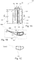
- FIGS. 1A to 1C illustrate examples of various views of the turbine component 100, such as turbine blade or stator vane, having one of an interchangeable connector.
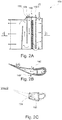
- FIGS. 2A to 2C illustrates examples of various views of the turbine component 100, having one of another interchangeable connector.
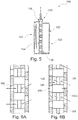
- the turbine components 100 in FIGS. 3 and 5 illustrate perspective views of the turbine components 100 with various types of inserts (described below), as per various embodiments of the disclosure, whereas FIGS.
- the turbine component 100 may be turbine blades, stator vanes or heat shields configured as a whole or as a part of the turbine.
- the turbine component 100 will be described with respect to the turbine blades, without departing from the scope of the stator vanes or heat shields or any other turbine components to include the limitations.
- blade 100 various associated elements may be well-known to those skilled in the art, it is not deemed necessary for purposes of acquiring an understanding of the present disclosure that there be recited herein all of the constructional details and explanation thereof. Rather, it is deemed sufficient to simply note that as shown in FIGS. 1 to 6B , in the blade 100, only those components are shown that are relevant for the description of various embodiments of the present disclosure.
- the blade 100 includes an airfoil profiled section 120, at least one cooling passageway 130, a plurality of film holes 140, and interchangeable connectors 180, 190.
- the airfoil profiled section 120 includes a pressure side 122 and a suction side 124 joined together at chordally opposite leading 126 and trailing 128 edges.
- the cooling passageway 130 is configured to extend between the pressure side 122 and the suction side 124 along the leading edge 126.
- the cooling passageway 130 is capable of enabling cooling fluid to flow therefrom, which it may receive from a fluid source, such as, the compressor of the engine, or any other source.
- a fluid source such as, the compressor of the engine, or any other source.
- the blade 100 further includes the plurality of film holes 140 extending between the cooling passageway 130 and an exterior of the airfoil profiled section 120.
- the plurality of film holes 140 (hereinafter referred to as 'film holes 140') may have a geometric configuration selected from one of a cylindrical, fan and console slot, without departing the scope of other geometric configuration as known in the art.
- the film holes 140 are capable of directing at least a portion of the cooling fluid from the cooling passageway 130 to flow over a portion of the airfoil profiled section 120 to form an air film cooling layer over the portion of the airfoil profiled section 120 for cooling thereto, and is termed as "the film cooling mode".
- the blade 100 is configured to include the interchangeable connectors 180, 190.
- the interchangeable connectors 180, 190 are configured to the cooling passageway 130, one at a time.
- the interchangeable connectors 180, 190 are adapted to change the cooling scheme by changing the flow of the cooling fluid in coordination with the opening and closing of the film holes 140.
- One of the interchangeable connector 180 as shown in FIGS. 1A to 1C , includes a covering bend 182.
- the connector 180 with the covering bend 182 is adapted to be secured via a suitable means, such as a sealing arrangement 184, over the cooling passageway 130.
- the connector 180 may be secured by various other suitable means such as, brazing, welding or other mechanical joint.
- the connector 180 enables at least a portion of the cooling fluid to flow from the leading edge 126 to the trailing edges 128 within an interior portion the airfoil profiled section 120, when the film holes 140 are closed.
- one of another interchangeable connector 190 includes a flat covering member 192 with an orifice 194.
- the interchangeable connector 190 is adapted to be secured via a suitable means, such as a sealing arrangement 196, over the cooling passageway 130.
- the connector 190 similar to connector 180, may also be secured by various other suitable means such as, brazing, welding or other mechanical joint.
- the connector 190 enables the cooling fluid from the orifice 194 to flow within the cooling passageway 130. Further, the cooling fluid from the cooling passageway 130 is directed towards the film holes 140 for flowing the cooling fluid to be flow from the leading edge 126 to the trailing edges 128, when the plurality of film holes 140 are opened, to form the film cooling layer extending from the leading edge 126 to the trailing edge 128.
- the interchangeable connectors 180, 190 are capable of changing the cooling schemes of the cooling fluid, irrespective of film or non-film cooling modes, in the blade 100 upon the requirement depending upon the temperature levels within the turbine.
- the blade 100 is adapted to include an insert 150.
- the insert 150 is capable of operably disposed within the cooling passageway 130 in coordination with the interchangeable connectors 180, 190 to at least partially close and open the film holes 140 in conjunction with the change in the cooling scheme.
- the insert 150 is operable to at least partially close the film holes 140 to interrupt the flow of the cooling fluid over the portion of the airfoil profiled section 120.
- the insert 150 is operable to open the film holes 140 to enable the flow of the cooling fluid over the portion of the airfoil profiled section 120 to form the air film cooling layer extending from the leading edge 126 to the trailing edge 128.
- the insert 150 may be a cylindrical rotating valve (referred to as numeral '152') adapted to be operable rotatably along an axis 'X' thereof to close and open the film holes 140.
- the cylindrical rotating valve 152 may include through-hole portions 152a such that the cylindrical rotating valve 152 is rotated to match and un-match through holes 152b of the through-hole portions 152a with the film holes 140, respectively, in the film and non-film cooling modes, to open and close the film holes 140 to enable and interrupt the cooling fluid.
- the insert 150 is a cylindrical switch (referred to as numeral '154') adapted to be operable to-and-fro vertically along an axis 'Y' thereof to close and open the film holes 140.
- the cylindrical switch 154 may include spaced apart fins 154a such that the cylindrical switch 154 is operable to-and-fro vertically to enable the fines 154a to match and un-match with the plurality of the film holes 140, respectively, to open and close thereto in the film and non-film cooling modes to enable and interrupt the cooling fluid.
- the insert 150 such as the cylindrical rotating valve 152 or the cylindrical switch 154
- the insert 150 may be operated manually, such as, to rotate along the axis 'X,' or move to-and-fro vertically along the axis 'Y,' respectively.
- the insert 150 such as the cylindrical rotating valve 152 or the cylindrical switch 154
- the cylindrical switch 154 may be located within the airfoil profiled section 120, which may be a mechanical switch or a replaceable part with orifices.
- the cylindrical rotating valve 152 or the cylindrical switch 154 may be accessible after engine disassembly and after disassembly of part, actual for turbine blades or after engine disassembly but without part disassembly, actual for turbine stator vanes.
- the cylindrical rotating valve 152or the cylindrical switch 154 may have active control, such as an element 156, for adapting the part efficiently during operation using remote activator, such as the hydraulic, pneumatic or electromechanical switches, or by using bi-metal devices.
- the blade 100 further includes a plurality of trailing through holes 160 configured on the leading edge 126 side in coordination with the cooling passageway 130.
- the trailing through holes 160 is configured to direct at least the portion of the cooling fluid from the cooling passageway 130 to flow within the interior portion of the airfoil profiled section 120 from the leading 126 to trailing 128 edges for internally cooling of the blade 100 or its airfoil profiled section 120.
- the plurality of trailing through holes 160 may be closable and openable by the insert 150 upon being operable as described above.
- the trailing edge 128 may include pin-fin bank 128a (as shown in FIGS.
- FIGS. 1A and 2A through which the cooling fluid after cooling the interior portion of the airfoil profiled section 120 may come.
- Various arrows in FIGS. 4A and 4B indicate direction of the flow of cooling air, without any limitation, by the film holes 140 and the trailing through holes 160.
- various arrows in FIGS. 6A and 6B indicate the direction of the flow of the cooling air from the cooling passageway 130 towards the airfoil profiled section 120 by the film holes 140 ( FIG. 6B ), and the direction of the flow of the cooling air from the cooling passageway 130 towards the trailing through holes 160 ( FIG. 6A ), for exemplary illustration.
- FIGS. 1A, 1B , 2A and 2B also indicates the direction of the cooling fluid flow.
- the blade 100 may also include an impingement cooling 132, which may receive the cooling fluid from the cooling passageway 130 to cool the leading edge 126.
- the blade 100 may also include channels 134, which may enables the exit of the cooling fluid from the leading edge 126 and direct the cooling air towards the trailing edge via a plurality of trailing through holes 160 for cooling the trailing edge 128.
- the plurality of trailing through holes 160 will be described herein later.
- the blade 100 may further include plurality fugitive plugs 170 (as shown only in FIG. 4A ).
- the fugitive plugs 170 may be adapted to be plugged in the film holes 140 in the non-film mode to protect the film holes 140 from hot gas injection and oxidation.
- the fugitive plugs 170 may be one of a ceramic plugs, metallic plugs, high temperature glue or ceramic plugs, thermal conductive bond coated plugs. In film cooling mode, the fugitive plugs 170 may be removed for opening the film holes 140 by the way of mechanically pressurizing or chemically decomposing, in-situ or remotely.
- the gas turbine components 100 such as the turbine blades or stator vanes or any other part such as heat shields, of the present disclosure are advantageous in various scopes.
- the gas turbine components 100 are optimized to deal with the change in cooling scheme in efficient manner so that required cooling scheme may be obtained easily in an economical and adaptable manner.
- the interchangeable connectors and the inserts are capable enabling the change of cooling scheme and reversible cooling scheme in economical manner eliminating the requirement of uneconomical castings.
Landscapes
- Engineering & Computer Science (AREA)
- Mechanical Engineering (AREA)
- General Engineering & Computer Science (AREA)
- Turbine Rotor Nozzle Sealing (AREA)
Applications Claiming Priority (2)
| Application Number | Priority Date | Filing Date | Title |
|---|---|---|---|
| RU2014103219/06A RU2568763C2 (ru) | 2014-01-30 | 2014-01-30 | Компонент газовой турбины |
| PCT/EP2015/051448 WO2015113925A1 (en) | 2014-01-30 | 2015-01-26 | Gas turbine component |
Publications (2)
| Publication Number | Publication Date |
|---|---|
| EP3099902A1 EP3099902A1 (en) | 2016-12-07 |
| EP3099902B1 true EP3099902B1 (en) | 2019-06-19 |
Family
ID=52394272
Family Applications (1)
| Application Number | Title | Priority Date | Filing Date |
|---|---|---|---|
| EP15700899.6A Active EP3099902B1 (en) | 2014-01-30 | 2015-01-26 | Gas turbine component |
Country Status (6)
Families Citing this family (3)
| Publication number | Priority date | Publication date | Assignee | Title |
|---|---|---|---|---|
| US9670797B2 (en) * | 2012-09-28 | 2017-06-06 | United Technologies Corporation | Modulated turbine vane cooling |
| RU2716648C1 (ru) * | 2019-07-16 | 2020-03-13 | ФЕДЕРАЛЬНОЕ ГОСУДАРСТВЕННОЕ БЮДЖЕТНОЕ ОБРАЗОВАТЕЛЬНОЕ УЧРЕЖДЕНИЕ ВЫСШЕГО ОБРАЗОВАНИЯ "Брянский государственный технический университет" | Охлаждаемая лопатка газовой турбины |
| US20250083804A1 (en) * | 2023-09-07 | 2025-03-13 | Textron Aviation Inc. | Winglet trailing edge venting |
Family Cites Families (20)
| Publication number | Priority date | Publication date | Assignee | Title |
|---|---|---|---|---|
| US3045965A (en) * | 1959-04-27 | 1962-07-24 | Rolls Royce | Turbine blades, vanes and the like |
| US3005496A (en) * | 1959-08-24 | 1961-10-24 | Hiller Aircraft Corp | Airfoil boundary layer control means |
| BE794195A (fr) * | 1972-01-18 | 1973-07-18 | Bbc Sulzer Turbomaschinen | Aube directrice refroidie pour des turbines a gaz |
| GB1530256A (en) * | 1975-04-01 | 1978-10-25 | Rolls Royce | Cooled blade for a gas turbine engine |
| US3937588A (en) * | 1974-07-24 | 1976-02-10 | United Technologies Corporation | Emergency control system for gas turbine engine variable compressor vanes |
| US4650399A (en) * | 1982-06-14 | 1987-03-17 | United Technologies Corporation | Rotor blade for a rotary machine |
| JPS62228603A (ja) * | 1986-03-31 | 1987-10-07 | Toshiba Corp | ガスタ−ビンの翼 |
| US5387086A (en) * | 1993-07-19 | 1995-02-07 | General Electric Company | Gas turbine blade with improved cooling |
| US5726348A (en) * | 1996-06-25 | 1998-03-10 | United Technologies Corporation | Process for precisely closing off cooling holes of an airfoil |
| JP2000517397A (ja) * | 1996-09-04 | 2000-12-26 | シーメンス アクチエンゲゼルシヤフト | 高温ガス流に曝されるタービン翼 |
| FR2765265B1 (fr) * | 1997-06-26 | 1999-08-20 | Snecma | Aubage refroidi par rampe helicoidale, par impact en cascade et par systeme a pontets dans une double peau |
| JP4087586B2 (ja) | 2001-09-13 | 2008-05-21 | 株式会社日立製作所 | ガスタービン及びその静翼 |
| RU2208683C1 (ru) * | 2002-01-08 | 2003-07-20 | Ульяновский государственный технический университет | Охлаждаемая лопатка турбины |
| DE10339857A1 (de) * | 2003-08-29 | 2005-03-24 | Daimlerchrysler Ag | Brennkraftmaschine mit einer Motorbremseinrichtung |
| EP1591626A1 (de) | 2004-04-30 | 2005-11-02 | Alstom Technology Ltd | Schaufel für Gasturbine |
| US7708229B1 (en) | 2006-03-22 | 2010-05-04 | West Virginia University | Circulation controlled airfoil |
| EP2407639A1 (en) | 2010-07-15 | 2012-01-18 | Siemens Aktiengesellschaft | Platform part for supporting a nozzle guide vane for a gas turbine |
| US20130104517A1 (en) | 2011-10-31 | 2013-05-02 | Victor Hugo Silva Correia | Component and method of fabricating the same |
| US9670797B2 (en) * | 2012-09-28 | 2017-06-06 | United Technologies Corporation | Modulated turbine vane cooling |
| US9664111B2 (en) * | 2012-12-19 | 2017-05-30 | United Technologies Corporation | Closure of cooling holes with a filing agent |
-
2014
- 2014-01-30 RU RU2014103219/06A patent/RU2568763C2/ru active
-
2015
- 2015-01-26 US US15/114,005 patent/US10883372B2/en active Active
- 2015-01-26 EP EP15700899.6A patent/EP3099902B1/en active Active
- 2015-01-26 JP JP2016549321A patent/JP2017504759A/ja active Pending
- 2015-01-26 CN CN201580006655.2A patent/CN105980662B/zh active Active
- 2015-01-26 WO PCT/EP2015/051448 patent/WO2015113925A1/en active Application Filing
Non-Patent Citations (1)
| Title |
|---|
| None * |
Also Published As
| Publication number | Publication date |
|---|---|
| WO2015113925A1 (en) | 2015-08-06 |
| CN105980662A (zh) | 2016-09-28 |
| RU2568763C2 (ru) | 2015-11-20 |
| US10883372B2 (en) | 2021-01-05 |
| US20160341047A1 (en) | 2016-11-24 |
| CN105980662B (zh) | 2018-06-22 |
| RU2014103219A (ru) | 2015-08-10 |
| EP3099902A1 (en) | 2016-12-07 |
| JP2017504759A (ja) | 2017-02-09 |
Similar Documents
| Publication | Publication Date | Title |
|---|---|---|
| CN103492677B (zh) | 燃气涡轮发动机中的翼型件 | |
| JP6063731B2 (ja) | タービンロータブレードプラットフォーム冷却 | |
| JP5898902B2 (ja) | タービン動翼のプラットフォーム区域を冷却するための装置及び方法 | |
| US9581028B1 (en) | Small turbine stator vane with impingement cooling insert | |
| US20130051972A1 (en) | Blade outer air seal with multi impingement plate assembly | |
| EP3150803B1 (en) | Airfoil and method of cooling | |
| US20190085705A1 (en) | Component for a turbine engine with a film-hole | |
| JP2007192213A (ja) | タービンエアフォイルおよびタービンエアフォイルアッセンブリを冷却する方法 | |
| EP3192971B1 (en) | Gas turbine blade with platform cooling and method | |
| JP2011208639A (ja) | 蛇行冷却されるプラットフォームを伴うガス・タービン動翼および関連する方法 | |
| EP3099902B1 (en) | Gas turbine component | |
| US20150198062A1 (en) | Turbine Components with Bi-Material Adaptive Cooling Pathways | |
| EP2226128B1 (en) | Method of coating a shield for a component | |
| JP2015528876A (ja) | 案内翼を製造するための方法および案内翼 | |
| US20170370230A1 (en) | Blade platform cooling in a gas turbine | |
| US8622701B1 (en) | Turbine blade platform with impingement cooling | |
| JP6632219B2 (ja) | 固定ブレード用の冷却構造体 | |
| US8622702B1 (en) | Turbine blade with cooling air inlet holes | |
| US8398371B1 (en) | Turbine blade with multiple near wall serpentine flow cooling | |
| EP3091182B1 (en) | Blade | |
| EP3020920B1 (en) | Cooling for turbine blade platform-aerofoil joints | |
| WO2015195088A1 (en) | Turbine airfoil cooling system with leading edge impingement cooling system | |
| EP3192972B1 (en) | Flow exchange baffle insert for a gas turbine engine component | |
| US11286788B2 (en) | Blade for a turbomachine turbine, comprising internal passages for circulating cooling air | |
| WO2017003457A1 (en) | Turbine blade with integrated multiple pass cooling circuits |
Legal Events
| Date | Code | Title | Description |
|---|---|---|---|
| PUAI | Public reference made under article 153(3) epc to a published international application that has entered the european phase |
Free format text: ORIGINAL CODE: 0009012 |
|
| STAA | Information on the status of an ep patent application or granted ep patent |
Free format text: STATUS: REQUEST FOR EXAMINATION WAS MADE |
|
| 17P | Request for examination filed |
Effective date: 20160729 |
|
| AK | Designated contracting states |
Kind code of ref document: A1 Designated state(s): AL AT BE BG CH CY CZ DE DK EE ES FI FR GB GR HR HU IE IS IT LI LT LU LV MC MK MT NL NO PL PT RO RS SE SI SK SM TR |
|
| AX | Request for extension of the european patent |
Extension state: BA ME |
|
| DAX | Request for extension of the european patent (deleted) | ||
| RAP1 | Party data changed (applicant data changed or rights of an application transferred) |
Owner name: ANSALDO ENERGIA IP UK LIMITED |
|
| STAA | Information on the status of an ep patent application or granted ep patent |
Free format text: STATUS: EXAMINATION IS IN PROGRESS |
|
| 17Q | First examination report despatched |
Effective date: 20180821 |
|
| GRAP | Despatch of communication of intention to grant a patent |
Free format text: ORIGINAL CODE: EPIDOSNIGR1 |
|
| STAA | Information on the status of an ep patent application or granted ep patent |
Free format text: STATUS: GRANT OF PATENT IS INTENDED |
|
| INTG | Intention to grant announced |
Effective date: 20190107 |
|
| GRAS | Grant fee paid |
Free format text: ORIGINAL CODE: EPIDOSNIGR3 |
|
| GRAA | (expected) grant |
Free format text: ORIGINAL CODE: 0009210 |
|
| STAA | Information on the status of an ep patent application or granted ep patent |
Free format text: STATUS: THE PATENT HAS BEEN GRANTED |
|
| AK | Designated contracting states |
Kind code of ref document: B1 Designated state(s): AL AT BE BG CH CY CZ DE DK EE ES FI FR GB GR HR HU IE IS IT LI LT LU LV MC MK MT NL NO PL PT RO RS SE SI SK SM TR |
|
| REG | Reference to a national code |
Ref country code: GB Ref legal event code: FG4D |
|
| REG | Reference to a national code |
Ref country code: CH Ref legal event code: EP |
|
| REG | Reference to a national code |
Ref country code: IE Ref legal event code: FG4D |
|
| REG | Reference to a national code |
Ref country code: DE Ref legal event code: R096 Ref document number: 602015032194 Country of ref document: DE |
|
| REG | Reference to a national code |
Ref country code: AT Ref legal event code: REF Ref document number: 1145754 Country of ref document: AT Kind code of ref document: T Effective date: 20190715 |
|
| REG | Reference to a national code |
Ref country code: NL Ref legal event code: MP Effective date: 20190619 |
|
| PG25 | Lapsed in a contracting state [announced via postgrant information from national office to epo] |
Ref country code: FI Free format text: LAPSE BECAUSE OF FAILURE TO SUBMIT A TRANSLATION OF THE DESCRIPTION OR TO PAY THE FEE WITHIN THE PRESCRIBED TIME-LIMIT Effective date: 20190619 Ref country code: LT Free format text: LAPSE BECAUSE OF FAILURE TO SUBMIT A TRANSLATION OF THE DESCRIPTION OR TO PAY THE FEE WITHIN THE PRESCRIBED TIME-LIMIT Effective date: 20190619 Ref country code: SE Free format text: LAPSE BECAUSE OF FAILURE TO SUBMIT A TRANSLATION OF THE DESCRIPTION OR TO PAY THE FEE WITHIN THE PRESCRIBED TIME-LIMIT Effective date: 20190619 Ref country code: HR Free format text: LAPSE BECAUSE OF FAILURE TO SUBMIT A TRANSLATION OF THE DESCRIPTION OR TO PAY THE FEE WITHIN THE PRESCRIBED TIME-LIMIT Effective date: 20190619 Ref country code: NO Free format text: LAPSE BECAUSE OF FAILURE TO SUBMIT A TRANSLATION OF THE DESCRIPTION OR TO PAY THE FEE WITHIN THE PRESCRIBED TIME-LIMIT Effective date: 20190919 Ref country code: AL Free format text: LAPSE BECAUSE OF FAILURE TO SUBMIT A TRANSLATION OF THE DESCRIPTION OR TO PAY THE FEE WITHIN THE PRESCRIBED TIME-LIMIT Effective date: 20190619 |
|
| REG | Reference to a national code |
Ref country code: LT Ref legal event code: MG4D |
|
| PG25 | Lapsed in a contracting state [announced via postgrant information from national office to epo] |
Ref country code: GR Free format text: LAPSE BECAUSE OF FAILURE TO SUBMIT A TRANSLATION OF THE DESCRIPTION OR TO PAY THE FEE WITHIN THE PRESCRIBED TIME-LIMIT Effective date: 20190920 Ref country code: BG Free format text: LAPSE BECAUSE OF FAILURE TO SUBMIT A TRANSLATION OF THE DESCRIPTION OR TO PAY THE FEE WITHIN THE PRESCRIBED TIME-LIMIT Effective date: 20190919 Ref country code: RS Free format text: LAPSE BECAUSE OF FAILURE TO SUBMIT A TRANSLATION OF THE DESCRIPTION OR TO PAY THE FEE WITHIN THE PRESCRIBED TIME-LIMIT Effective date: 20190619 Ref country code: LV Free format text: LAPSE BECAUSE OF FAILURE TO SUBMIT A TRANSLATION OF THE DESCRIPTION OR TO PAY THE FEE WITHIN THE PRESCRIBED TIME-LIMIT Effective date: 20190619 |
|
| REG | Reference to a national code |
Ref country code: AT Ref legal event code: MK05 Ref document number: 1145754 Country of ref document: AT Kind code of ref document: T Effective date: 20190619 |
|
| PG25 | Lapsed in a contracting state [announced via postgrant information from national office to epo] |
Ref country code: SK Free format text: LAPSE BECAUSE OF FAILURE TO SUBMIT A TRANSLATION OF THE DESCRIPTION OR TO PAY THE FEE WITHIN THE PRESCRIBED TIME-LIMIT Effective date: 20190619 Ref country code: PT Free format text: LAPSE BECAUSE OF FAILURE TO SUBMIT A TRANSLATION OF THE DESCRIPTION OR TO PAY THE FEE WITHIN THE PRESCRIBED TIME-LIMIT Effective date: 20191021 Ref country code: EE Free format text: LAPSE BECAUSE OF FAILURE TO SUBMIT A TRANSLATION OF THE DESCRIPTION OR TO PAY THE FEE WITHIN THE PRESCRIBED TIME-LIMIT Effective date: 20190619 Ref country code: AT Free format text: LAPSE BECAUSE OF FAILURE TO SUBMIT A TRANSLATION OF THE DESCRIPTION OR TO PAY THE FEE WITHIN THE PRESCRIBED TIME-LIMIT Effective date: 20190619 Ref country code: RO Free format text: LAPSE BECAUSE OF FAILURE TO SUBMIT A TRANSLATION OF THE DESCRIPTION OR TO PAY THE FEE WITHIN THE PRESCRIBED TIME-LIMIT Effective date: 20190619 Ref country code: NL Free format text: LAPSE BECAUSE OF FAILURE TO SUBMIT A TRANSLATION OF THE DESCRIPTION OR TO PAY THE FEE WITHIN THE PRESCRIBED TIME-LIMIT Effective date: 20190619 Ref country code: CZ Free format text: LAPSE BECAUSE OF FAILURE TO SUBMIT A TRANSLATION OF THE DESCRIPTION OR TO PAY THE FEE WITHIN THE PRESCRIBED TIME-LIMIT Effective date: 20190619 |
|
| PG25 | Lapsed in a contracting state [announced via postgrant information from national office to epo] |
Ref country code: SM Free format text: LAPSE BECAUSE OF FAILURE TO SUBMIT A TRANSLATION OF THE DESCRIPTION OR TO PAY THE FEE WITHIN THE PRESCRIBED TIME-LIMIT Effective date: 20190619 Ref country code: ES Free format text: LAPSE BECAUSE OF FAILURE TO SUBMIT A TRANSLATION OF THE DESCRIPTION OR TO PAY THE FEE WITHIN THE PRESCRIBED TIME-LIMIT Effective date: 20190619 Ref country code: IT Free format text: LAPSE BECAUSE OF FAILURE TO SUBMIT A TRANSLATION OF THE DESCRIPTION OR TO PAY THE FEE WITHIN THE PRESCRIBED TIME-LIMIT Effective date: 20190619 Ref country code: IS Free format text: LAPSE BECAUSE OF FAILURE TO SUBMIT A TRANSLATION OF THE DESCRIPTION OR TO PAY THE FEE WITHIN THE PRESCRIBED TIME-LIMIT Effective date: 20191019 |
|
| PG25 | Lapsed in a contracting state [announced via postgrant information from national office to epo] |
Ref country code: TR Free format text: LAPSE BECAUSE OF FAILURE TO SUBMIT A TRANSLATION OF THE DESCRIPTION OR TO PAY THE FEE WITHIN THE PRESCRIBED TIME-LIMIT Effective date: 20190619 |
|
| PG25 | Lapsed in a contracting state [announced via postgrant information from national office to epo] |
Ref country code: PL Free format text: LAPSE BECAUSE OF FAILURE TO SUBMIT A TRANSLATION OF THE DESCRIPTION OR TO PAY THE FEE WITHIN THE PRESCRIBED TIME-LIMIT Effective date: 20190619 Ref country code: DK Free format text: LAPSE BECAUSE OF FAILURE TO SUBMIT A TRANSLATION OF THE DESCRIPTION OR TO PAY THE FEE WITHIN THE PRESCRIBED TIME-LIMIT Effective date: 20190619 |
|
| PG25 | Lapsed in a contracting state [announced via postgrant information from national office to epo] |
Ref country code: IS Free format text: LAPSE BECAUSE OF FAILURE TO SUBMIT A TRANSLATION OF THE DESCRIPTION OR TO PAY THE FEE WITHIN THE PRESCRIBED TIME-LIMIT Effective date: 20200224 |
|
| REG | Reference to a national code |
Ref country code: DE Ref legal event code: R097 Ref document number: 602015032194 Country of ref document: DE |
|
| PLBE | No opposition filed within time limit |
Free format text: ORIGINAL CODE: 0009261 |
|
| STAA | Information on the status of an ep patent application or granted ep patent |
Free format text: STATUS: NO OPPOSITION FILED WITHIN TIME LIMIT |
|
| PG2D | Information on lapse in contracting state deleted |
Ref country code: IS |
|
| 26N | No opposition filed |
Effective date: 20200603 |
|
| PG25 | Lapsed in a contracting state [announced via postgrant information from national office to epo] |
Ref country code: MC Free format text: LAPSE BECAUSE OF FAILURE TO SUBMIT A TRANSLATION OF THE DESCRIPTION OR TO PAY THE FEE WITHIN THE PRESCRIBED TIME-LIMIT Effective date: 20190619 Ref country code: SI Free format text: LAPSE BECAUSE OF FAILURE TO SUBMIT A TRANSLATION OF THE DESCRIPTION OR TO PAY THE FEE WITHIN THE PRESCRIBED TIME-LIMIT Effective date: 20190619 |
|
| REG | Reference to a national code |
Ref country code: CH Ref legal event code: PL |
|
| REG | Reference to a national code |
Ref country code: BE Ref legal event code: MM Effective date: 20200131 |
|
| PG25 | Lapsed in a contracting state [announced via postgrant information from national office to epo] |
Ref country code: LU Free format text: LAPSE BECAUSE OF NON-PAYMENT OF DUE FEES Effective date: 20200126 Ref country code: FR Free format text: LAPSE BECAUSE OF NON-PAYMENT OF DUE FEES Effective date: 20200131 |
|
| PG25 | Lapsed in a contracting state [announced via postgrant information from national office to epo] |
Ref country code: LI Free format text: LAPSE BECAUSE OF NON-PAYMENT OF DUE FEES Effective date: 20200131 Ref country code: BE Free format text: LAPSE BECAUSE OF NON-PAYMENT OF DUE FEES Effective date: 20200131 Ref country code: CH Free format text: LAPSE BECAUSE OF NON-PAYMENT OF DUE FEES Effective date: 20200131 |
|
| PG25 | Lapsed in a contracting state [announced via postgrant information from national office to epo] |
Ref country code: IE Free format text: LAPSE BECAUSE OF NON-PAYMENT OF DUE FEES Effective date: 20200126 |
|
| PG25 | Lapsed in a contracting state [announced via postgrant information from national office to epo] |
Ref country code: MT Free format text: LAPSE BECAUSE OF FAILURE TO SUBMIT A TRANSLATION OF THE DESCRIPTION OR TO PAY THE FEE WITHIN THE PRESCRIBED TIME-LIMIT Effective date: 20190619 Ref country code: CY Free format text: LAPSE BECAUSE OF FAILURE TO SUBMIT A TRANSLATION OF THE DESCRIPTION OR TO PAY THE FEE WITHIN THE PRESCRIBED TIME-LIMIT Effective date: 20190619 |
|
| PG25 | Lapsed in a contracting state [announced via postgrant information from national office to epo] |
Ref country code: MK Free format text: LAPSE BECAUSE OF FAILURE TO SUBMIT A TRANSLATION OF THE DESCRIPTION OR TO PAY THE FEE WITHIN THE PRESCRIBED TIME-LIMIT Effective date: 20190619 |
|
| P01 | Opt-out of the competence of the unified patent court (upc) registered |
Effective date: 20240430 |
|
| PGFP | Annual fee paid to national office [announced via postgrant information from national office to epo] |
Ref country code: DE Payment date: 20250120 Year of fee payment: 11 |
|
| PGFP | Annual fee paid to national office [announced via postgrant information from national office to epo] |
Ref country code: GB Payment date: 20250123 Year of fee payment: 11 |