EP3099577B1 - Système d'alimentation amélioré en ergol pour un véhicule spatial - Google Patents
Système d'alimentation amélioré en ergol pour un véhicule spatial Download PDFInfo
- Publication number
- EP3099577B1 EP3099577B1 EP15704063.5A EP15704063A EP3099577B1 EP 3099577 B1 EP3099577 B1 EP 3099577B1 EP 15704063 A EP15704063 A EP 15704063A EP 3099577 B1 EP3099577 B1 EP 3099577B1
- Authority
- EP
- European Patent Office
- Prior art keywords
- actuator
- valve
- tank
- feed
- configuration
- Prior art date
- Legal status (The legal status is an assumption and is not a legal conclusion. Google has not performed a legal analysis and makes no representation as to the accuracy of the status listed.)
- Active
Links
Images
Classifications
-
- B—PERFORMING OPERATIONS; TRANSPORTING
- B64—AIRCRAFT; AVIATION; COSMONAUTICS
- B64G—COSMONAUTICS; VEHICLES OR EQUIPMENT THEREFOR
- B64G5/00—Ground equipment for vehicles, e.g. starting towers, fuelling arrangements
-
- B—PERFORMING OPERATIONS; TRANSPORTING
- B64—AIRCRAFT; AVIATION; COSMONAUTICS
- B64G—COSMONAUTICS; VEHICLES OR EQUIPMENT THEREFOR
- B64G1/00—Cosmonautic vehicles
- B64G1/22—Parts of, or equipment specially adapted for fitting in or to, cosmonautic vehicles
- B64G1/40—Arrangements or adaptations of propulsion systems
- B64G1/402—Propellant tanks; Feeding propellants
-
- F—MECHANICAL ENGINEERING; LIGHTING; HEATING; WEAPONS; BLASTING
- F02—COMBUSTION ENGINES; HOT-GAS OR COMBUSTION-PRODUCT ENGINE PLANTS
- F02K—JET-PROPULSION PLANTS
- F02K9/00—Rocket-engine plants, i.e. plants carrying both fuel and oxidant therefor; Control thereof
- F02K9/42—Rocket-engine plants, i.e. plants carrying both fuel and oxidant therefor; Control thereof using liquid or gaseous propellants
- F02K9/60—Constructional parts; Details not otherwise provided for
- F02K9/605—Reservoirs
-
- F—MECHANICAL ENGINEERING; LIGHTING; HEATING; WEAPONS; BLASTING
- F05—INDEXING SCHEMES RELATING TO ENGINES OR PUMPS IN VARIOUS SUBCLASSES OF CLASSES F01-F04
- F05D—INDEXING SCHEME FOR ASPECTS RELATING TO NON-POSITIVE-DISPLACEMENT MACHINES OR ENGINES, GAS-TURBINES OR JET-PROPULSION PLANTS
- F05D2220/00—Application
- F05D2220/80—Application in supersonic vehicles excluding hypersonic vehicles or ram, scram or rocket propulsion
Definitions
- the present invention relates to the field of propellant refueling systems of a spacecraft, and finds an application particularly for cryogenic or non-cryogenic thrusters of a launcher.
- Propellant refueling of a spacecraft such as a rocket must be performed as close as possible to takeoff, in order to minimize the storage time of the propellant in the rocket tanks.
- the existing devices for propellant feed tanks of a spacecraft cf. FR 2 943 626 , create significant pressure drops, which significantly reduce the filling rate of the tanks and considerably lengthen the filling time, thereby increasing the storage time of the propellant in the tanks of the spacecraft.
- cryogenic propellant makes problematic the use of certain technologies, in particular the use of electromagnetic actuators, which are not compatible with such temperatures, for example of the order of -253 ° C.
- the actuator is typically coupled to an elastic return means exerting a thrust force on the actuator tending to move it to the open configuration in which the actuator opens the valve.
- the system then advantageously comprises a control, for example pneumatic, adapted to exert a force on the actuator opposing the thrust force applied by the elastic return means, so as to tend to move the actuator to the configuration closed.
- the actuator can be coupled to an elastic return means exerting a thrust force on the actuator tending to move it to the closed configuration in which the actuator closes the valve.
- the system then advantageously comprises a control, for example pneumatic, adapted to exert a force on the actuator opposing the thrust force applied by the elastic return means, so as to tend to move the actuator to the configuration opened.
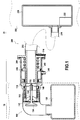
- the figure 1 represents a propellant feed system according to one aspect of the invention in a feed configuration.
- This figure shows an edge edge 10 and a ground side 20, respectively corresponding to equipment on board a spacecraft, and equipment mounted on the ground.
- the power system shown on the figure 1 thus includes edge-side equipment 10, and ground-side equipment 20.
- the valve 134 is arranged in such a way that, depending on its displacement in the valve guide 130, it closes off the supply orifice 112 or not.
- a guide element 140 is advantageously positioned between the valve guide 130 and the frame 110.
- the valve guide 130 is coupled to a thrust means 160 adapted to, in the absence of application of additional forces, exert a thrust force on the valve guide 130 so as to maintain the valve 134 in the position of closing the supply port 112.
- the free end 212 of the supply duct 210 is arranged opposite the supply orifice 112 of the frame 110.
- the actuator 250 is thus also arranged facing the supply port 112 of the frame 110.
- the actuator 250 is configured so that when the edge device 100 and the ground device 200 are so associated, the end free 252 of the actuator 250 comes into contact with the movable element 130, preferably substantially at the outer periphery of the moving element 130.
- the actuator 250 can thus control the displacement of the valve 130, and thus the opening or not of the supply orifice 112, for example by moving the valve guide 130 so that the valve 134 closes or not channels arranged in the vicinity of the supply port 112.
- the elastic return means 260 as shown exerts a thrust force on the actuator 250 tending to move the valve guide 130 so that the valve 134 opens the supply port 112 and thus allow the fluid passage of the conduit supply 210 to the tank edge 120.
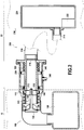
- control pressure via the control orifice 245 makes it possible to drive the actuator 250 so as to reduce or even cancel the thrust force that it exerts as the valve 130; the valve 130 is then returned to a closed configuration by the thrust means 160, in which the valve 134 closes the supply port 112, as shown in FIG. figure 2 .
- the control of the opening or the closing of the supply orifice 112 can thus be carried out by means of a pressure control applied via the control orifice 245.
- the actuator 250 undergoes a thrust force exerted by the elastic return means 260 tending to open the supply port 112; here, therefore, control of the opening of the feed orifice 112 is carried out.
- An inverted configuration can also be carried out, in which the closure of the supply orifice 112 is controlled.
- the elastic return means is then configured so as to exert a force tending to move the actuator 250 so as to cancel or at least minimize the force it applies to the valve guide 130, the valve 134 thus closing the supply port 112 in the absence of pressure applied via the control port 245.
- the supply duct 210 is connected to the ground tank 220, which is associated with a transfer system 222 typically comprising a pump, configured so as to make it possible to transfer fluid, such as propellant, from the ground tank 220 to the ground.
- a transfer system 222 typically comprising a pump, configured so as to make it possible to transfer fluid, such as propellant, from the ground tank 220 to the ground.
- tank edge 120 through the supply duct 210 and the supply port 112.
- a shutter 214 is also positioned near the free end 212 of the supply duct 210, adapted to, in a shutter configuration, close the supply duct 210, and in a supply configuration, allow a transfer of fluid from the ground tank 220 to the tank edge 120.
- the shutter 214 is shown in the feed configuration on the figure 1 and in shutter configuration on the figure 2 .
- An initial configuration is considered in which the edge device 100 and the ground device 200 are joined.
- the shutter 214 is closed, as well as the valve 134.
- the tank edge 120 and the tank 220 are thus isolated from one another.
- the edge device 100 and the ground device 200 are associated, as shown in FIG. figure 1 .
- the inlet orifice 112 is opened by the actuator 250.
- the shutter 214 is open, and the transfer system 222 is operated so as to fill the tank edge 120 with fluid contained in the ground tank 220. Once the tank edge 120 filled to the desired level, the filling ceases.
- the actuator 250 is controlled so as to no longer exert an opening force on the valve guide 130 of the valve 134, the valve body 134 thus closing the supply orifice 112 so that the tank edge 120 is isolated from the supply duct 210.
- the transfer system 222 stops sending fluid from the ground tank 220 to the supply duct 210.
- the supply duct 210 is then filled with fluid.
- the supply pipe 210 is drained so as to purge the fluid therein, and then the shutter 214 is closed.
- the emptying of the supply duct is typically carried out by means of a drainage system, which may, for example, put the supply duct 210 under pressure. Sealing tests can then be carried out in the supply duct 210, making it possible in particular to check the tightness of the valve 134.
- the spacecraft can take off, the edge device 100 and the ground device 200 are then separated.
- the positioning of the actuator 250 on the outer periphery of the supply duct 210 and not within the supply duct 210 makes it possible to limit the presence of components arranged in the supply duct 210, and therefore to limit Disturbances of the fluid flow in the feed pipe 210.
- the pressure losses are thus limited, the flow rate can be increased and thus the filling of the edge tank 120 can be accelerated for a reduced edge edge valve diameter 134.
- the positioning of the actuator 250 at the outer periphery of the supply condition 210 and the offset to the outside of the ducts of the control elements of the actuator 250 also makes it possible to have a supply duct aligned with the orifice supply 112, which is advantageous in terms of reduction of pressure drops.
- the proposed actuator structure 250 and actuator control system is also compatible with cryogenic propellants such as commonly used for spacecraft that reach temperatures of the order of -253 ° C, and are therefore incompatible with certain types of actuators such as magnetic actuators.
- ground device 200 presented can be used without requiring structural modifications at the edge device 100. Only the dimensions of the supply duct 210 and the actuator 250 play a role in the actuation of the valve 134. The proposed ground device 200 can thus be associated with existing edge devices 100.
Landscapes
- Engineering & Computer Science (AREA)
- Aviation & Aerospace Engineering (AREA)
- Remote Sensing (AREA)
- Chemical & Material Sciences (AREA)
- Combustion & Propulsion (AREA)
- General Physics & Mathematics (AREA)
- Astronomy & Astrophysics (AREA)
- Physics & Mathematics (AREA)
- Mechanical Engineering (AREA)
- General Engineering & Computer Science (AREA)
- Filling Or Discharging Of Gas Storage Vessels (AREA)
- Loading And Unloading Of Fuel Tanks Or Ships (AREA)
- Fluid-Driven Valves (AREA)
- Fluid-Pressure Circuits (AREA)
Description
- La présente invention concerne le domaine des systèmes d'avitaillement en ergol d'un engin spatial, et trouve une application notamment pour des propulseurs cryogéniques ou non cryogéniques d'un lanceur.
- L'avitaillement en ergol d'un engin spatial tel qu'une fusée doit être réalisé au plus près possible du décollage, afin de limiter au maximum la durée de stockage de l'ergol dans les réservoirs de la fusée.
Cependant, les dispositifs existants pour l'alimentation en ergol des réservoirs d'un engin spatial, cf.FR 2 943 626 - De plus, l'utilisation d'un ergol cryogénique rend problématique l'utilisation de certaines technologies, notamment l'utilisation d'actionneurs électromagnétiques, qui ne sont pas compatibles avec des telles températures par exemple de l'ordre de -253°C.
- Enfin, la modification de composants sur un engin spatial est problématique, en ce qu'elle implique la réalisation de nombreux essais, complexes et longs à réaliser. Les modifications côté bord, c'est-à-dire au niveau de la structure de l'engin spatial sont donc à éviter.
- Afin de répondre au moins partiellement à ces diverses problématiques, la présente invention propose un système d'alimentation en ergol d'un véhicule spatial, comprenant
- un dispositif bord comprenant
- un châssis présentant un orifice d'alimentation menant à un réservoir bord,
- une soupape adaptée pour sélectivement obturer ou ouvrir ledit orifice d'alimentation,
- un dispositif sol comprenant
- un conduit d'alimentation présentant une extrémité libre,
- un corps de vannage muni d'un actionneur,
- dans une configuration d'alimentation, relier ledit conduit d'alimentation au réservoir sol,
- dans une configuration d'obturation, isoler le conduit d'alimentation du réservoir sol.
- L'actionneur est typiquement couplé à un moyen de rappel élastique exerçant un effort de poussée sur l'actionneur tendant à le déplacer vers la configuration ouverte dans laquelle l'actionneur ouvre la soupape.
Le système comprend alors avantageusement une commande, par exemple pneumatique, adaptée pour exercer un effort sur l'actionneur s'opposant à l'effort de poussée appliquée par le moyen de rappel élastique, de manière à tendre à déplacer l'actionneur vers la configuration fermée. - A l'inverse, l'actionneur peut être couplé à un moyen de rappel élastique exerçant un effort de poussée sur l'actionneur tendant à le déplacer vers la configuration fermée dans laquelle l'actionneur ferme la soupape.
Le système comprend alors avantageusement une commande, par exemple pneumatique, adaptée pour exercer un effort sur l'actionneur s'opposant à l'effort de poussée appliquée par le moyen de rappel élastique, de manière à tendre à déplacer l'actionneur vers la configuration ouverte. - D'autres caractéristiques, buts et avantages de l'invention ressortiront de la description qui suit, qui est purement illustrative et non limitative, et qui doit être lue en regard des dessins annexés, sur lesquels :
- La
figure 1 représente un système d'alimentation en ergol selon un aspect de l'invention dans une configuration d'alimentation, - La
figure 2 présente le système de lafigure 1 dans une configuration fermée. - Sur l'ensemble des figures, les éléments en commun sont repérés par des références numériques identiques.
- La
figure 1 représente un système d'alimentation en ergol selon un aspect de l'invention dans une configuration d'alimentation. - On repère sur cette figure un côté bord 10 et un côté sol 20, correspondant respectivement à des équipements embarqués sur un engin spatial, et à des équipements montés au sol.
- Le système d'alimentation représenté sur la
figure 1 comprend ainsi des équipements côté bord 10, et des équipements côté sol 20. - Plus précisément, le système illustré comprend côté bord 10 un dispositif bord 100 comprenant :
- un châssis 110 présentant un orifice d'alimentation 112 relié à un réservoir bord 120 ;
- une soupape 134 montée coulissante et couplée à un guide de soupape 130, adaptée pour sélectivement obturer ou non l'orifice d'alimentation 112 du châssis 110.
- La soupape 134 est disposée de manière à, en fonction de son déplacement dans le guide de soupape 130, obturer ou non l'orifice d'alimentation 112.
Un élément de guidage 140 est avantageusement positionné entre le guide de soupape 130 et le châssis 110.
Le guide de soupape 130 est couplé à un moyen de poussée 160 adapté pour, en l'absence d'application d'efforts additionnels, exercer un effort de poussée sur le guide de soupape 130 de manière à maintenir la soupape 134 en position d'obturation de l'orifice d'alimentation 112. - Du côté sol 20, on représente sur la
figure 1 un dispositif sol 200 comprenant : - un conduit d'alimentation 210 présentant une extrémité libre 212,
- un réservoir sol 220 monté dans une structure de lancement 230.
- Lorsque le dispositif bord 100 et le dispositif sol 200 sont associés, l'extrémité libre 212 du conduit d'alimentation 210 est disposés en regard de l'orifice d'alimentation 112 du châssis 110.
L'actionneur 250 est donc également disposé en regard de l'orifice d'alimentation 112 du châssis 110. L'actionneur 250 est configuré de manière à ce que lorsque le dispositif bord 100 et le dispositif sol 200 sont ainsi associés, l'extrémité libre 252 de l'actionneur 250 vienne au contact de l'équipage mobile 130, avantageusement sensiblement à la périphérie externe de l'équipage mobile 130. - L'actionneur 250 peut ainsi piloter le déplacement de la soupape 130, et donc l'ouverture ou non de l'orifice d'alimentation 112, par exemple en déplaçant le guide de soupape 130 de sorte que la soupape 134 obture ou non des canaux d'alimentation aménagés à proximité de l'orifice d'alimentation 112.
Le moyen de rappel élastique 260 tel que présenté exerce un effort de poussée sur l'actionneur 250 tendant à déplacer le guide de soupape 130 afin que la soupape 134 ouvre l'orifice d'alimentation 112 et ainsi permettre le passage de fluide du conduit d'alimentation 210 vers le réservoir bord 120.
A l'inverse, l'application d'une pression de commande via l'orifice de commande 245 permet de piloter l'actionneur 250 de manière à réduire voire annuler l'effort de poussée qu'il exerce que la soupape 130 ; la soupape 130 est alors ramenée dans une configuration fermée par le moyen de poussée 160, dans laquelle la soupape 134 obture l'orifice d'alimentation 112, comme représenté sur lafigure 2 . - Le pilotage de l'ouverture ou de la fermeture de l'orifice d'alimentation 112 peut donc être effectué au moyen d'un pilotage en pression appliquée via l'orifice de commande 245.
Dans le mode de réalisation représenté, en l'absence de pression de commande appliquée via l'orifice de commande 245, l'actionneur 250 subit un effort de poussée exercé par le moyen de rappel élastique 260 tendant à ouvrir l'orifice d'alimentation 112 ; on réalise donc ici un pilotage de de l'ouverture de l'orifice d'alimentation 112.
Une configuration inversée peut également être réalisée, dans laquelle on réalise un pilotage de la fermeture de l'orifice d'alimentation 112. Le moyen de rappel élastique est alors configuré de manière à exercer un effort tendant à déplacer l'actionneur 250 de manière à annuler ou à tout le moins à minimiser l'effort qu'il applique sur le guide de soupape 130, la soupape 134 obturant donc l'orifice d'alimentation 112 en l'absence de pression appliquée via l'orifice de commande 245. - Le conduit d'alimentation 210 est relié au réservoir sol 220, qui est associé à un système de transfert 222 comprenant typiquement une pompe, configuré de manière à permettre de transférer du fluide, tel que de l'ergol, du réservoir sol 220 vers le réservoir bord 120 par l'intermédiaire du conduit d'alimentation 210 et de l'orifice d'alimentation 112.
- Un obturateur 214 est également positionné à proximité de l'extrémité libre 212 du conduit d'alimentation 210, adapté pour, dans une configuration d'obturation, obturer le conduit d'alimentation 210, et dans une configuration d'alimentation, permettre un transfert de fluide du réservoir sol 220 vers le réservoir bord 120. L'obturateur 214 est représenté en configuration d'alimentation sur la
figure 1 et en configuration d'obturation sur lafigure 2 . - On décrit ensuite un exemple de fonctionnement du système présenté.
- On considère une configuration initiale dans laquelle le dispositif bord 100 et le dispositif sol 200 sont joints. L'obturateur 214 est fermé, de même que la soupape 134. Le réservoir bord 120 et le réservoir sol 220 sont ainsi isolés l'un par rapport à l'autre.
- Le dispositif bord 100 et le dispositif sol 200 sont associés, comme représenté sur la
figure 1 . L'orifice d'admission 112 est ouvert par l'actionneur 250.
L'obturateur 214 est ouvert, et le système de transfert 222 est mis en fonctionnement de manière à remplir le réservoir bord 120 de fluide contenu dans le réservoir sol 220.
Une fois le réservoir bord 120 rempli au niveau souhaité, le remplissage cesse. L'actionneur 250 est piloté de manière à ne plus exercer un effort d'ouverture sur le guide de soupape 130 de la soupape 134, le corps de soupape 134 obturant ainsi l'orifice d'alimentation 112 de sorte que le réservoir bord 120 soit isolé du conduit d'alimentation 210. Le système de transfert 222 cesse d'envoyer du fluide du réservoir sol 220 vers le conduit d'alimentation 210. - Le conduit d'alimentation 210 est alors rempli de fluide. Afin d'éviter que ce fluide ne se déverse lorsque le dispositif bord 100 et le dispositif sol 200 se séparent, on vidange le conduit d'alimentation 210 de manière à purger le fluide s'y trouvant, puis l'obturateur 214 est fermé. La vidange du conduit d'alimentation est typiquement réalisée au moyen d'un système de vidange, pouvant par exemple mettre sous pression le conduit d'alimentation 210.
Des tests d'étanchéité peuvent alors être réalisés dans le conduit d'alimentation 210, permettant notamment de vérifier l'étanchéité de la soupape 134. - Une fois les tests effectués, l'engin spatial peut décoller, le dispositif bord 100 et le dispositif sol 200 sont alors séparés.
- Le système proposé présente ainsi plusieurs avantages.
En premier lieu, le positionnement de l'actionneur 250 sur la périphérie externe du conduit d'alimentation 210 et non pas au sein du conduit d'alimentation 210 permet de limiter la présence de composants disposés dans le conduit d'alimentation 210, et donc de limiter les perturbations de l'écoulement de fluide dans le conduit d'alimentation 210. Les pertes de charge sont ainsi limitées, le débit peut être augmenté et donc le remplissage du réservoir bord 120 peut être accéléré pour un diamètre de soupape 134 côté bord réduit.
Le positionnement de l'actionneur 250 en périphérie externe du condit d'alimentation 210 et le déport sur l'extérieur des conduits des éléments de pilotage de l'actionneur 250 permet également d'avoir un conduit d'alimentation aligné avec l'orifice d'alimentation 112, ce qui est avantageux en terme de réduction des pertes de charge. - La structure proposée d'actionneur 250 et de système de pilotage de l'actionneur est de plus compatible avec des ergols cryogéniques tels que couramment utilisés pour les engins spatiaux qui atteignent des températures de l'ordre de -253°C, et sont donc incompatibles avec certains type d'actionneurs tels que les actionneurs magnétiques.
- Enfin, le dispositif sol 200 présenté peut être employé sans nécessiter de modifications structurelles au niveau du dispositif bord 100. Seules les dimensions du conduit d'alimentation 210 et de l'actionneur 250 jouent un rôle dans l'actionnement de la soupape 134. Le dispositif sol 200 proposé peut ainsi être associé à des dispositifs bord 100 existants.
le système étant caractérisé en ce que le corps de vannage entoure ladite extrémité libre du conduit d'alimentation et ledit actionneur entoure la périphérie externe du conduit d'alimentation.
La présente invention propose ainsi un système d'alimentation en ergol pour un engin spatial dans lequel les pertes de charge au niveau de la jonction entre l'engin spatial et les équipements au sol sont minimisées, et le temps de remplissage du réservoir de l'engin spatial est ainsi fortement réduit. De plus, les dimensions du clapet sont réduites, contribuant de ce fait à une réduction de la masse embarquée.
Le système proposé peut en outre être utilisé sur des engins spatiaux existants, sans nécessiter de modification sur l'engin spatial lui-même. Enfin, le système proposé est compatible avec un ergol cryogénique.
Selon un mode de réalisation particulier, le dispositif sol comprend une structure de lancement comprenant un réservoir sol auquel est relié le conduit d'alimentation, la structure de lancement comprenant en outre un obturateur adapté pour,
Le système d'alimentation en ergol peut alors comprendre en outre des moyens de détection de fuites adaptés pour réaliser des tests d'étanchéité dans ledit conduit d'alimentation lorsque la soupape obture l'orifice d'alimentation.
Le corps de vannage 240 est équipé d'un actionneur 250 monté coulissant autour de l'extrémité libre 212, sur la périphérie externe du conduit d'alimentation 210. L'actionneur 250 est couplé à un moyen de rappel élastique 260, ici un ressort de poussée, exerçant un effort de poussée sur l'actionneur 250 tendant à le déplacer de sorte qu'une extrémité libre 252 de l'actionneur 250 s'étende au-delà de l'extrémité libre 212 du conduit d'alimentation 210.
Le corps de vannage 240 tel que présenté comprend également un orifice de commande 245, adapté pour permettre l'application d'une pression de commande sur l'actionneur 250 s'opposant à l'effort de poussée exercé par le moyen de rappel élastique 260, et permettant ainsi de déplacer l'actionneur 250 de manière à ramener son extrémité libre 252 vers l'extrémité libre 212 du conduit d'alimentation 210.
Claims (9)
- Système d'alimentation en ergol d'un véhicule spatial, comprenant- un dispositif bord (100) comprenant• un châssis (110) présentant un orifice d'alimentation (112) menant à un réservoir bord (120),• une soupape (134) adaptée pour sélectivement obturer ou ouvrir ledit orifice d'alimentation (112),- un dispositif sol (200) comprenantle dispositif bord (100) et le dispositif sol (200) étant configurés de manière à pouvoir être associés afin de, dans une configuration ouverte, permettre un transfert d'ergol du conduit d'alimentation (210) vers le réservoir bord (120), et dans une configuration fermée, isoler le réservoir bord (120) du conduit d'alimentation (210), l'actionneur (250) étant configuré de manière à piloter l'ouverture et l'obturation de l'orifice d'alimentation (112) par la soupape (134),• un conduit d'alimentation (210) présentant une extrémité libre (212),• un corps de vannage (240) muni d'un actionneur (250),
le système étant caractérisé en ce que le corps de vannage (240) entoure ladite extrémité libre (212) du conduit d'alimentation (210) et en ce que ledit actionneur (250) entoure la périphérie externe du conduit d'alimentation (210). - Système selon la revendication 1, dans lequel le dispositif sol comprend une structure de lancement (230) comprenant un réservoir sol (220) auquel est relié le conduit d'alimentation (210), ledit système comprenant en outre un obturateur (214) adapté pour,- dans une configuration d'alimentation, permettre un transfert d'ergol entre le réservoir sol (220) et le réservoir bord (120),- dans une configuration d'obturation, isoler le réservoir bord (120) du réservoir sol (220).
- Système selon la revendication 2, dans lequel ladite structure de lancement comprend en outre un système de vidange adapté pour réaliser une purge du conduit d'alimentation (210) de sorte que lors de l'application d'une commande, ledit système de transfert aspire l'ergol contenu dans le conduit d'alimentation (210) et le stocke dans un réservoir de la base.
- Système selon l'une des revendications 2 ou 3, comprenant en outre des moyens de détection de fuites adaptés pour réaliser des tests d'étanchéité dans ledit conduit d'alimentation (210) lorsque la soupape (134) obture l'orifice d'alimentation (112).
- Système selon l'une des revendications 1 à 4, dans lequel ledit actionneur (250) est couplé à un moyen de rappel élastique (260) exerçant un effort de poussée sur l'actionneur (250) tendant à le déplacer vers une configuration ouverte dans laquelle l'actionneur (250) ouvre la soupape (134).
- Système selon la revendication 5, comprenant une commande (245) adaptée pour exercer un effort sur l'actionneur (250) s'opposant à l'effort de poussée appliquée par le moyen de rappel élastique (260), de manière à tendre à déplacer l'actionneur vers la configuration fermée.
- Système selon l'une des revendications 1 à 4, dans lequel ledit actionneur (250) est couplé à un moyen de rappel élastique (260) exerçant un effort de poussée sur l'actionneur (250) tendant à le déplacer vers la configuration fermée dans laquelle l'actionneur (250) ferme la soupape (134) de sorte que la soupape (134) obture l'orifice d'alimentation (112).
- Système selon la revendication 7, comprenant une commande (245) adaptée pour exercer un effort sur l'actionneur (250) s'opposant à l'effort de poussée appliquée par le moyen de rappel élastique (260), de manière à tendre à déplacer l'actionneur (250) vers la configuration ouverte dans laquelle la soupape (134) n'obture pas l'orifice d'alimentation (112).
- Système selon l'une des revendications 6 ou 8, dans lequel ladite commande (245) est une commande pneumatique.
Applications Claiming Priority (2)
| Application Number | Priority Date | Filing Date | Title |
|---|---|---|---|
| FR1400227A FR3016865B1 (fr) | 2014-01-29 | 2014-01-29 | Systeme d'alimentation ameliore en ergol pour un vehicule spatial |
| PCT/FR2015/050157 WO2015114238A1 (fr) | 2014-01-29 | 2015-01-22 | Système d'alimentation amélioré en ergol pour un véhicule spatial |
Publications (2)
| Publication Number | Publication Date |
|---|---|
| EP3099577A1 EP3099577A1 (fr) | 2016-12-07 |
| EP3099577B1 true EP3099577B1 (fr) | 2018-05-16 |
Family
ID=51292996
Family Applications (1)
| Application Number | Title | Priority Date | Filing Date |
|---|---|---|---|
| EP15704063.5A Active EP3099577B1 (fr) | 2014-01-29 | 2015-01-22 | Système d'alimentation amélioré en ergol pour un véhicule spatial |
Country Status (6)
| Country | Link |
|---|---|
| US (1) | US10308376B2 (fr) |
| EP (1) | EP3099577B1 (fr) |
| JP (1) | JP6529978B2 (fr) |
| FR (1) | FR3016865B1 (fr) |
| RU (1) | RU2667020C2 (fr) |
| WO (1) | WO2015114238A1 (fr) |
Cited By (1)
| Publication number | Priority date | Publication date | Assignee | Title |
|---|---|---|---|---|
| CN110406700A (zh) * | 2019-07-02 | 2019-11-05 | 蓝箭航天空间科技股份有限公司 | 一种用于火箭储箱推进剂加注的低温连接器 |
Families Citing this family (3)
| Publication number | Priority date | Publication date | Assignee | Title |
|---|---|---|---|---|
| CN109896049B (zh) * | 2018-11-22 | 2021-06-18 | 北京航天发射技术研究所 | 一种直角坐标柔性非接触式连接器自动对接装置及方法 |
| US11958640B2 (en) | 2020-12-28 | 2024-04-16 | Sener Aeroespacial, S.A. | Connection system and connecting method for transferring fluids between two vehicles or between a vehicle and a fixed structure |
| CN117869122B (zh) * | 2024-03-11 | 2024-06-14 | 江苏深蓝航天有限公司 | 一种推进剂控制装置 |
Family Cites Families (19)
| Publication number | Priority date | Publication date | Assignee | Title |
|---|---|---|---|---|
| US4609169A (en) * | 1984-08-14 | 1986-09-02 | The United States Of America As Represented By The Secretary Of The Air Force | Propellant tank resupply system |
| JP3176955B2 (ja) | 1990-06-19 | 2001-06-18 | 株式会社東芝 | 冷媒用弁装置 |
| US5404923A (en) * | 1993-05-26 | 1995-04-11 | Rockwell International Corporation | Apparatus for automated fueling of a launch vehicle |
| US5582366A (en) * | 1995-01-19 | 1996-12-10 | Motorola, Inc. | Satellite fueling system and method therefor |
| US5904302A (en) * | 1997-03-21 | 1999-05-18 | Brown; Albert W. | Aircraft fueling nozzle |
| JPH11230402A (ja) | 1998-02-13 | 1999-08-27 | Asahi Organic Chem Ind Co Ltd | 排出弁 |
| US6125871A (en) * | 1999-01-22 | 2000-10-03 | Ashland, Inc. | Valve assembly with flush and sample capability |
| US6142194A (en) * | 1999-03-09 | 2000-11-07 | Cla-Val | Pressure fuel servicing nozzle |
| JP2002005378A (ja) * | 2000-06-23 | 2002-01-09 | Ishikawajima Harima Heavy Ind Co Ltd | 極低温配管の結合装置 |
| RU2225813C2 (ru) * | 2002-02-04 | 2004-03-20 | Открытое акционерное общество "Ракетно-космическая корпорация "Энергия" им. С.П.Королева" | Способ заправки жидким кислородом бака окислителя ракетной двигательной установки |
| FR2849144B1 (fr) * | 2002-12-18 | 2005-10-21 | Snecma Moteurs | Dispositif de vanne cryogenique a actionneur pneumatique |
| JP5078219B2 (ja) * | 2004-04-26 | 2012-11-21 | 三菱重工業株式会社 | 接続具、流体供給システム、接続具接続方法、及び接続具分離方法 |
| US7575200B2 (en) * | 2005-09-07 | 2009-08-18 | The Boeing Company | Space depot for spacecraft resupply |
| US8074935B2 (en) * | 2007-03-09 | 2011-12-13 | Macdonald Dettwiler & Associates Inc. | Satellite refuelling system and method |
| FR2943626B1 (fr) * | 2009-03-30 | 2011-04-22 | Snecma | Dispositif d'avitaillement de propulseurs d'un lanceur |
| US8820353B2 (en) * | 2010-06-30 | 2014-09-02 | Carleton Technologies, Inc. | Interface assembly for space vehicles |
| WO2013082719A1 (fr) * | 2011-12-05 | 2013-06-13 | Macdonald Dettwiler & Associates Inc. | Système et outil permettant d'accéder aux vannes de remplissage/vidange d'un satellite durant le ravitaillement en propergol |
| US9231323B1 (en) * | 2014-07-28 | 2016-01-05 | NovaWurks, Inc. | Spacecraft docking connector |
| FR3029173B1 (fr) * | 2014-11-28 | 2018-03-23 | Arianegroup Sas | Dispositif et procede de deverrouillage d'un dispositif d'avitaillement |
-
2014
- 2014-01-29 FR FR1400227A patent/FR3016865B1/fr active Active
-
2015
- 2015-01-22 US US15/114,228 patent/US10308376B2/en active Active
- 2015-01-22 WO PCT/FR2015/050157 patent/WO2015114238A1/fr not_active Ceased
- 2015-01-22 RU RU2016135001A patent/RU2667020C2/ru active
- 2015-01-22 JP JP2016549503A patent/JP6529978B2/ja active Active
- 2015-01-22 EP EP15704063.5A patent/EP3099577B1/fr active Active
Non-Patent Citations (1)
| Title |
|---|
| None * |
Cited By (1)
| Publication number | Priority date | Publication date | Assignee | Title |
|---|---|---|---|---|
| CN110406700A (zh) * | 2019-07-02 | 2019-11-05 | 蓝箭航天空间科技股份有限公司 | 一种用于火箭储箱推进剂加注的低温连接器 |
Also Published As
| Publication number | Publication date |
|---|---|
| US20170008649A1 (en) | 2017-01-12 |
| JP6529978B2 (ja) | 2019-06-12 |
| RU2016135001A (ru) | 2018-03-05 |
| JP2017504538A (ja) | 2017-02-09 |
| FR3016865A1 (fr) | 2015-07-31 |
| EP3099577A1 (fr) | 2016-12-07 |
| FR3016865B1 (fr) | 2016-02-19 |
| RU2016135001A3 (fr) | 2018-07-11 |
| RU2667020C2 (ru) | 2018-09-13 |
| US10308376B2 (en) | 2019-06-04 |
| WO2015114238A1 (fr) | 2015-08-06 |
Similar Documents
| Publication | Publication Date | Title |
|---|---|---|
| EP2414242B1 (fr) | Dispositif d'avitaillement de propulseurs d'un lanceur | |
| WO2015114238A1 (fr) | Système d'alimentation amélioré en ergol pour un véhicule spatial | |
| EP3436706B1 (fr) | Bloc de sécurité à double clapet pour vérin hydraulique | |
| WO1998020260A2 (fr) | Dispositif de maintien en position de la tige d'un verin hydraulique | |
| WO2018019801A1 (fr) | Régulateur de débit de ventilation pour un réservoir pressurisé de véhicule | |
| EP2778364A1 (fr) | Dispositif de commande de l'alimentation d'un système avec un fluide | |
| FR2794101A1 (fr) | Actionneur pneumatique | |
| JP2012521927A5 (fr) | ||
| EP3578871B1 (fr) | Dispositif de fourniture de fluide sous pression | |
| FR2991750A1 (fr) | Dispositif de controle pour bouteille de fluide sous pression et bouteille correspondante | |
| EP3925893A1 (fr) | Procédé de dépressurisation d'une cabine d'un aéronef au sol depuis l extérieur de l aéronef | |
| EP4455021B1 (fr) | Aéronef comprenant au moins un dispositif d'alimentation en hydrogène équipé d'au moins un système d'évacuation de gaz en cas de fuite | |
| EP3098403B1 (fr) | Dispositif de commande d'une alimentation en fluide sous pression | |
| EP2901057B1 (fr) | Clapet de ventilation pour réservoir à liquide intégrant une sécurité anti-surpression | |
| CA2719464A1 (fr) | Dispositif receveur de gaz sous pression, ensemble distributeur-dispositif receveur, et systeme d'alimentation correspondant | |
| FR2976064A1 (fr) | Engin sous-marin comportant des moyens de lancement d'un vehicule sous-marin | |
| FR2976065A1 (fr) | Engin sous-marin comportant des moyens de lancement d'un vehicule sous-marin en auto-demarrage | |
| EP0597768A1 (fr) | Système de sécurité pour véhicule routier fonctionnant au combustible gazeux | |
| CA3079703C (fr) | Aeronef muni d'un systeme de ravitaillement de carburant en vol | |
| EP4296168A1 (fr) | Système de réservoir avec une vanne sous forme d'un système pendulaire | |
| EP0494818A1 (fr) | Dispositif de remplissage à distance d'un réservoir d'huile | |
| EP3775645B1 (fr) | Vanne de regulation amelioree avec fonction de purge integree | |
| EP3393965B1 (fr) | Equipement comprenant une vanne coaxiale insérable pour transférer un fluide dans un réservoir et procédé | |
| FR3003839A1 (fr) | Engin sous-marin comportant au moins un tube externe de reception et de lancement d'un vehicule sous-marin | |
| FR3035922A1 (fr) | Dispositif d'inversion de poussee pour un turboreacteur d'aeronef, et nacelle comportant le dispositif |
Legal Events
| Date | Code | Title | Description |
|---|---|---|---|
| PUAI | Public reference made under article 153(3) epc to a published international application that has entered the european phase |
Free format text: ORIGINAL CODE: 0009012 |
|
| STAA | Information on the status of an ep patent application or granted ep patent |
Free format text: STATUS: REQUEST FOR EXAMINATION WAS MADE |
|
| 17P | Request for examination filed |
Effective date: 20160826 |
|
| AK | Designated contracting states |
Kind code of ref document: A1 Designated state(s): AL AT BE BG CH CY CZ DE DK EE ES FI FR GB GR HR HU IE IS IT LI LT LU LV MC MK MT NL NO PL PT RO RS SE SI SK SM TR |
|
| AX | Request for extension of the european patent |
Extension state: BA ME |
|
| DAX | Request for extension of the european patent (deleted) | ||
| REG | Reference to a national code |
Ref country code: DE Ref legal event code: R079 Ref document number: 602015011144 Country of ref document: DE Free format text: PREVIOUS MAIN CLASS: B64G0005000000 Ipc: F02K0009600000 |
|
| GRAP | Despatch of communication of intention to grant a patent |
Free format text: ORIGINAL CODE: EPIDOSNIGR1 |
|
| STAA | Information on the status of an ep patent application or granted ep patent |
Free format text: STATUS: GRANT OF PATENT IS INTENDED |
|
| RIC1 | Information provided on ipc code assigned before grant |
Ipc: B64G 5/00 20060101ALI20170531BHEP Ipc: F02K 9/60 20060101AFI20170531BHEP |
|
| INTG | Intention to grant announced |
Effective date: 20170626 |
|
| GRAJ | Information related to disapproval of communication of intention to grant by the applicant or resumption of examination proceedings by the epo deleted |
Free format text: ORIGINAL CODE: EPIDOSDIGR1 |
|
| STAA | Information on the status of an ep patent application or granted ep patent |
Free format text: STATUS: REQUEST FOR EXAMINATION WAS MADE |
|
| GRAP | Despatch of communication of intention to grant a patent |
Free format text: ORIGINAL CODE: EPIDOSNIGR1 |
|
| STAA | Information on the status of an ep patent application or granted ep patent |
Free format text: STATUS: GRANT OF PATENT IS INTENDED |
|
| INTC | Intention to grant announced (deleted) | ||
| INTG | Intention to grant announced |
Effective date: 20171128 |
|
| GRAS | Grant fee paid |
Free format text: ORIGINAL CODE: EPIDOSNIGR3 |
|
| GRAA | (expected) grant |
Free format text: ORIGINAL CODE: 0009210 |
|
| STAA | Information on the status of an ep patent application or granted ep patent |
Free format text: STATUS: THE PATENT HAS BEEN GRANTED |
|
| AK | Designated contracting states |
Kind code of ref document: B1 Designated state(s): AL AT BE BG CH CY CZ DE DK EE ES FI FR GB GR HR HU IE IS IT LI LT LU LV MC MK MT NL NO PL PT RO RS SE SI SK SM TR |
|
| REG | Reference to a national code |
Ref country code: GB Ref legal event code: FG4D Free format text: NOT ENGLISH |
|
| REG | Reference to a national code |
Ref country code: CH Ref legal event code: EP |
|
| REG | Reference to a national code |
Ref country code: IE Ref legal event code: FG4D Free format text: LANGUAGE OF EP DOCUMENT: FRENCH |
|
| REG | Reference to a national code |
Ref country code: DE Ref legal event code: R096 Ref document number: 602015011144 Country of ref document: DE |
|
| REG | Reference to a national code |
Ref country code: AT Ref legal event code: REF Ref document number: 999814 Country of ref document: AT Kind code of ref document: T Effective date: 20180615 |
|
| REG | Reference to a national code |
Ref country code: SE Ref legal event code: TRGR |
|
| REG | Reference to a national code |
Ref country code: NL Ref legal event code: MP Effective date: 20180516 |
|
| REG | Reference to a national code |
Ref country code: LT Ref legal event code: MG4D |
|
| PG25 | Lapsed in a contracting state [announced via postgrant information from national office to epo] |
Ref country code: FI Free format text: LAPSE BECAUSE OF FAILURE TO SUBMIT A TRANSLATION OF THE DESCRIPTION OR TO PAY THE FEE WITHIN THE PRESCRIBED TIME-LIMIT Effective date: 20180516 Ref country code: NO Free format text: LAPSE BECAUSE OF FAILURE TO SUBMIT A TRANSLATION OF THE DESCRIPTION OR TO PAY THE FEE WITHIN THE PRESCRIBED TIME-LIMIT Effective date: 20180816 Ref country code: BG Free format text: LAPSE BECAUSE OF FAILURE TO SUBMIT A TRANSLATION OF THE DESCRIPTION OR TO PAY THE FEE WITHIN THE PRESCRIBED TIME-LIMIT Effective date: 20180816 Ref country code: ES Free format text: LAPSE BECAUSE OF FAILURE TO SUBMIT A TRANSLATION OF THE DESCRIPTION OR TO PAY THE FEE WITHIN THE PRESCRIBED TIME-LIMIT Effective date: 20180516 Ref country code: LT Free format text: LAPSE BECAUSE OF FAILURE TO SUBMIT A TRANSLATION OF THE DESCRIPTION OR TO PAY THE FEE WITHIN THE PRESCRIBED TIME-LIMIT Effective date: 20180516 |
|
| RAP2 | Party data changed (patent owner data changed or rights of a patent transferred) |
Owner name: CENTRE NATIONAL D'ETUDES SPATIALES |
|
| PG25 | Lapsed in a contracting state [announced via postgrant information from national office to epo] |
Ref country code: LV Free format text: LAPSE BECAUSE OF FAILURE TO SUBMIT A TRANSLATION OF THE DESCRIPTION OR TO PAY THE FEE WITHIN THE PRESCRIBED TIME-LIMIT Effective date: 20180516 Ref country code: HR Free format text: LAPSE BECAUSE OF FAILURE TO SUBMIT A TRANSLATION OF THE DESCRIPTION OR TO PAY THE FEE WITHIN THE PRESCRIBED TIME-LIMIT Effective date: 20180516 Ref country code: NL Free format text: LAPSE BECAUSE OF FAILURE TO SUBMIT A TRANSLATION OF THE DESCRIPTION OR TO PAY THE FEE WITHIN THE PRESCRIBED TIME-LIMIT Effective date: 20180516 Ref country code: GR Free format text: LAPSE BECAUSE OF FAILURE TO SUBMIT A TRANSLATION OF THE DESCRIPTION OR TO PAY THE FEE WITHIN THE PRESCRIBED TIME-LIMIT Effective date: 20180817 Ref country code: RS Free format text: LAPSE BECAUSE OF FAILURE TO SUBMIT A TRANSLATION OF THE DESCRIPTION OR TO PAY THE FEE WITHIN THE PRESCRIBED TIME-LIMIT Effective date: 20180516 |
|
| RAP2 | Party data changed (patent owner data changed or rights of a patent transferred) |
Owner name: CENTRE NATIONAL D'ETUDES SPATIALES Owner name: SAFRAN AIRCRAFT ENGINES |
|
| REG | Reference to a national code |
Ref country code: AT Ref legal event code: MK05 Ref document number: 999814 Country of ref document: AT Kind code of ref document: T Effective date: 20180516 |
|
| PG25 | Lapsed in a contracting state [announced via postgrant information from national office to epo] |
Ref country code: PL Free format text: LAPSE BECAUSE OF FAILURE TO SUBMIT A TRANSLATION OF THE DESCRIPTION OR TO PAY THE FEE WITHIN THE PRESCRIBED TIME-LIMIT Effective date: 20180516 Ref country code: EE Free format text: LAPSE BECAUSE OF FAILURE TO SUBMIT A TRANSLATION OF THE DESCRIPTION OR TO PAY THE FEE WITHIN THE PRESCRIBED TIME-LIMIT Effective date: 20180516 Ref country code: DK Free format text: LAPSE BECAUSE OF FAILURE TO SUBMIT A TRANSLATION OF THE DESCRIPTION OR TO PAY THE FEE WITHIN THE PRESCRIBED TIME-LIMIT Effective date: 20180516 Ref country code: RO Free format text: LAPSE BECAUSE OF FAILURE TO SUBMIT A TRANSLATION OF THE DESCRIPTION OR TO PAY THE FEE WITHIN THE PRESCRIBED TIME-LIMIT Effective date: 20180516 Ref country code: AT Free format text: LAPSE BECAUSE OF FAILURE TO SUBMIT A TRANSLATION OF THE DESCRIPTION OR TO PAY THE FEE WITHIN THE PRESCRIBED TIME-LIMIT Effective date: 20180516 Ref country code: CZ Free format text: LAPSE BECAUSE OF FAILURE TO SUBMIT A TRANSLATION OF THE DESCRIPTION OR TO PAY THE FEE WITHIN THE PRESCRIBED TIME-LIMIT Effective date: 20180516 Ref country code: SK Free format text: LAPSE BECAUSE OF FAILURE TO SUBMIT A TRANSLATION OF THE DESCRIPTION OR TO PAY THE FEE WITHIN THE PRESCRIBED TIME-LIMIT Effective date: 20180516 |
|
| REG | Reference to a national code |
Ref country code: DE Ref legal event code: R097 Ref document number: 602015011144 Country of ref document: DE |
|
| PG25 | Lapsed in a contracting state [announced via postgrant information from national office to epo] |
Ref country code: SM Free format text: LAPSE BECAUSE OF FAILURE TO SUBMIT A TRANSLATION OF THE DESCRIPTION OR TO PAY THE FEE WITHIN THE PRESCRIBED TIME-LIMIT Effective date: 20180516 |
|
| PLBE | No opposition filed within time limit |
Free format text: ORIGINAL CODE: 0009261 |
|
| STAA | Information on the status of an ep patent application or granted ep patent |
Free format text: STATUS: NO OPPOSITION FILED WITHIN TIME LIMIT |
|
| 26N | No opposition filed |
Effective date: 20190219 |
|
| PG25 | Lapsed in a contracting state [announced via postgrant information from national office to epo] |
Ref country code: SI Free format text: LAPSE BECAUSE OF FAILURE TO SUBMIT A TRANSLATION OF THE DESCRIPTION OR TO PAY THE FEE WITHIN THE PRESCRIBED TIME-LIMIT Effective date: 20180516 |
|
| PG25 | Lapsed in a contracting state [announced via postgrant information from national office to epo] |
Ref country code: MC Free format text: LAPSE BECAUSE OF FAILURE TO SUBMIT A TRANSLATION OF THE DESCRIPTION OR TO PAY THE FEE WITHIN THE PRESCRIBED TIME-LIMIT Effective date: 20180516 |
|
| REG | Reference to a national code |
Ref country code: CH Ref legal event code: PL |
|
| PG25 | Lapsed in a contracting state [announced via postgrant information from national office to epo] |
Ref country code: LU Free format text: LAPSE BECAUSE OF NON-PAYMENT OF DUE FEES Effective date: 20190122 |
|
| REG | Reference to a national code |
Ref country code: BE Ref legal event code: MM Effective date: 20190131 |
|
| REG | Reference to a national code |
Ref country code: IE Ref legal event code: MM4A |
|
| PG25 | Lapsed in a contracting state [announced via postgrant information from national office to epo] |
Ref country code: AL Free format text: LAPSE BECAUSE OF FAILURE TO SUBMIT A TRANSLATION OF THE DESCRIPTION OR TO PAY THE FEE WITHIN THE PRESCRIBED TIME-LIMIT Effective date: 20180516 Ref country code: BE Free format text: LAPSE BECAUSE OF NON-PAYMENT OF DUE FEES Effective date: 20190131 |
|
| PG25 | Lapsed in a contracting state [announced via postgrant information from national office to epo] |
Ref country code: CH Free format text: LAPSE BECAUSE OF NON-PAYMENT OF DUE FEES Effective date: 20190131 Ref country code: LI Free format text: LAPSE BECAUSE OF NON-PAYMENT OF DUE FEES Effective date: 20190131 |
|
| PG25 | Lapsed in a contracting state [announced via postgrant information from national office to epo] |
Ref country code: IE Free format text: LAPSE BECAUSE OF NON-PAYMENT OF DUE FEES Effective date: 20190122 |
|
| PG25 | Lapsed in a contracting state [announced via postgrant information from national office to epo] |
Ref country code: TR Free format text: LAPSE BECAUSE OF FAILURE TO SUBMIT A TRANSLATION OF THE DESCRIPTION OR TO PAY THE FEE WITHIN THE PRESCRIBED TIME-LIMIT Effective date: 20180516 |
|
| PG25 | Lapsed in a contracting state [announced via postgrant information from national office to epo] |
Ref country code: PT Free format text: LAPSE BECAUSE OF FAILURE TO SUBMIT A TRANSLATION OF THE DESCRIPTION OR TO PAY THE FEE WITHIN THE PRESCRIBED TIME-LIMIT Effective date: 20180917 Ref country code: MT Free format text: LAPSE BECAUSE OF FAILURE TO SUBMIT A TRANSLATION OF THE DESCRIPTION OR TO PAY THE FEE WITHIN THE PRESCRIBED TIME-LIMIT Effective date: 20180516 |
|
| PG25 | Lapsed in a contracting state [announced via postgrant information from national office to epo] |
Ref country code: CY Free format text: LAPSE BECAUSE OF FAILURE TO SUBMIT A TRANSLATION OF THE DESCRIPTION OR TO PAY THE FEE WITHIN THE PRESCRIBED TIME-LIMIT Effective date: 20180516 |
|
| PG25 | Lapsed in a contracting state [announced via postgrant information from national office to epo] |
Ref country code: IS Free format text: LAPSE BECAUSE OF FAILURE TO SUBMIT A TRANSLATION OF THE DESCRIPTION OR TO PAY THE FEE WITHIN THE PRESCRIBED TIME-LIMIT Effective date: 20180916 |
|
| PG25 | Lapsed in a contracting state [announced via postgrant information from national office to epo] |
Ref country code: HU Free format text: LAPSE BECAUSE OF FAILURE TO SUBMIT A TRANSLATION OF THE DESCRIPTION OR TO PAY THE FEE WITHIN THE PRESCRIBED TIME-LIMIT; INVALID AB INITIO Effective date: 20150122 |
|
| PG25 | Lapsed in a contracting state [announced via postgrant information from national office to epo] |
Ref country code: MK Free format text: LAPSE BECAUSE OF FAILURE TO SUBMIT A TRANSLATION OF THE DESCRIPTION OR TO PAY THE FEE WITHIN THE PRESCRIBED TIME-LIMIT Effective date: 20180516 |
|
| PGFP | Annual fee paid to national office [announced via postgrant information from national office to epo] |
Ref country code: SE Payment date: 20260121 Year of fee payment: 12 |
|
| PGFP | Annual fee paid to national office [announced via postgrant information from national office to epo] |
Ref country code: GB Payment date: 20260122 Year of fee payment: 12 |
|
| PGFP | Annual fee paid to national office [announced via postgrant information from national office to epo] |
Ref country code: DE Payment date: 20260120 Year of fee payment: 12 |
|
| PGFP | Annual fee paid to national office [announced via postgrant information from national office to epo] |
Ref country code: IT Payment date: 20260130 Year of fee payment: 12 |
|
| PGFP | Annual fee paid to national office [announced via postgrant information from national office to epo] |
Ref country code: FR Payment date: 20260128 Year of fee payment: 12 |