EP3099396B1 - Fluidtrennsysteme und -verfahren - Google Patents
Fluidtrennsysteme und -verfahren Download PDFInfo
- Publication number
- EP3099396B1 EP3099396B1 EP14880887.6A EP14880887A EP3099396B1 EP 3099396 B1 EP3099396 B1 EP 3099396B1 EP 14880887 A EP14880887 A EP 14880887A EP 3099396 B1 EP3099396 B1 EP 3099396B1
- Authority
- EP
- European Patent Office
- Prior art keywords
- fluid
- fluid inlet
- vessel
- polymerization reactor
- reactor
- Prior art date
- Legal status (The legal status is an assumption and is not a legal conclusion. Google has not performed a legal analysis and makes no representation as to the accuracy of the status listed.)
- Active
Links
- 239000012530 fluid Substances 0.000 title claims description 251
- 238000000926 separation method Methods 0.000 title claims description 52
- 238000000034 method Methods 0.000 title claims description 17
- 238000006116 polymerization reaction Methods 0.000 claims description 46
- 239000002826 coolant Substances 0.000 claims description 28
- 239000002245 particle Substances 0.000 claims description 20
- 230000004907 flux Effects 0.000 claims description 19
- 239000011541 reaction mixture Substances 0.000 claims description 16
- 238000011144 upstream manufacturing Methods 0.000 claims description 10
- 238000007599 discharging Methods 0.000 claims description 5
- 229920000642 polymer Polymers 0.000 description 15
- 239000000203 mixture Substances 0.000 description 13
- 239000007788 liquid Substances 0.000 description 9
- 239000007789 gas Substances 0.000 description 6
- -1 polyethylene Polymers 0.000 description 6
- VGGSQFUCUMXWEO-UHFFFAOYSA-N Ethene Chemical compound C=C VGGSQFUCUMXWEO-UHFFFAOYSA-N 0.000 description 5
- 239000005977 Ethylene Substances 0.000 description 5
- 150000001336 alkenes Chemical class 0.000 description 5
- 239000003054 catalyst Substances 0.000 description 5
- 239000007787 solid Substances 0.000 description 5
- 239000004698 Polyethylene Substances 0.000 description 4
- 230000003993 interaction Effects 0.000 description 4
- 239000000178 monomer Substances 0.000 description 4
- JRZJOMJEPLMPRA-UHFFFAOYSA-N olefin Natural products CCCCCCCC=C JRZJOMJEPLMPRA-UHFFFAOYSA-N 0.000 description 4
- 229920000573 polyethylene Polymers 0.000 description 4
- 230000008569 process Effects 0.000 description 4
- 239000003999 initiator Substances 0.000 description 3
- QQONPFPTGQHPMA-UHFFFAOYSA-N propylene Natural products CC=C QQONPFPTGQHPMA-UHFFFAOYSA-N 0.000 description 3
- 125000004805 propylene group Chemical group [H]C([H])([H])C([H])([*:1])C([H])([H])[*:2] 0.000 description 3
- 238000006276 transfer reaction Methods 0.000 description 3
- 239000004743 Polypropylene Substances 0.000 description 2
- 230000004888 barrier function Effects 0.000 description 2
- 230000007423 decrease Effects 0.000 description 2
- 229910052739 hydrogen Inorganic materials 0.000 description 2
- 239000001257 hydrogen Substances 0.000 description 2
- 125000004435 hydrogen atom Chemical class [H]* 0.000 description 2
- 238000004519 manufacturing process Methods 0.000 description 2
- VNWKTOKETHGBQD-UHFFFAOYSA-N methane Chemical compound C VNWKTOKETHGBQD-UHFFFAOYSA-N 0.000 description 2
- 229920000098 polyolefin Polymers 0.000 description 2
- 229920001155 polypropylene Polymers 0.000 description 2
- 238000012545 processing Methods 0.000 description 2
- 230000003068 static effect Effects 0.000 description 2
- OKTJSMMVPCPJKN-UHFFFAOYSA-N Carbon Chemical compound [C] OKTJSMMVPCPJKN-UHFFFAOYSA-N 0.000 description 1
- 229910000831 Steel Inorganic materials 0.000 description 1
- 239000000654 additive Substances 0.000 description 1
- 230000009172 bursting Effects 0.000 description 1
- 229910052799 carbon Inorganic materials 0.000 description 1
- 230000000052 comparative effect Effects 0.000 description 1
- 230000002508 compound effect Effects 0.000 description 1
- 238000013461 design Methods 0.000 description 1
- 230000005611 electricity Effects 0.000 description 1
- 230000003116 impacting effect Effects 0.000 description 1
- 239000000463 material Substances 0.000 description 1
- 150000002978 peroxides Chemical class 0.000 description 1
- 230000002028 premature Effects 0.000 description 1
- 238000010298 pulverizing process Methods 0.000 description 1
- 238000010791 quenching Methods 0.000 description 1
- 238000010008 shearing Methods 0.000 description 1
- 230000035939 shock Effects 0.000 description 1
- 239000002002 slurry Substances 0.000 description 1
- 239000002904 solvent Substances 0.000 description 1
- 239000010959 steel Substances 0.000 description 1
- 238000013022 venting Methods 0.000 description 1
- XLYOFNOQVPJJNP-UHFFFAOYSA-N water Substances O XLYOFNOQVPJJNP-UHFFFAOYSA-N 0.000 description 1
- 239000004711 α-olefin Substances 0.000 description 1
Images


Classifications
-
- B—PERFORMING OPERATIONS; TRANSPORTING
- B01—PHYSICAL OR CHEMICAL PROCESSES OR APPARATUS IN GENERAL
- B01D—SEPARATION
- B01D21/00—Separation of suspended solid particles from liquids by sedimentation
- B01D21/26—Separation of sediment aided by centrifugal force or centripetal force
- B01D21/267—Separation of sediment aided by centrifugal force or centripetal force by using a cyclone
-
- B—PERFORMING OPERATIONS; TRANSPORTING
- B01—PHYSICAL OR CHEMICAL PROCESSES OR APPARATUS IN GENERAL
- B01J—CHEMICAL OR PHYSICAL PROCESSES, e.g. CATALYSIS OR COLLOID CHEMISTRY; THEIR RELEVANT APPARATUS
- B01J8/00—Chemical or physical processes in general, conducted in the presence of fluids and solid particles; Apparatus for such processes
- B01J8/005—Separating solid material from the gas/liquid stream
- B01J8/0055—Separating solid material from the gas/liquid stream using cyclones
-
- B—PERFORMING OPERATIONS; TRANSPORTING
- B01—PHYSICAL OR CHEMICAL PROCESSES OR APPARATUS IN GENERAL
- B01D—SEPARATION
- B01D45/00—Separating dispersed particles from gases or vapours by gravity, inertia, or centrifugal forces
- B01D45/12—Separating dispersed particles from gases or vapours by gravity, inertia, or centrifugal forces by centrifugal forces
-
- B—PERFORMING OPERATIONS; TRANSPORTING
- B01—PHYSICAL OR CHEMICAL PROCESSES OR APPARATUS IN GENERAL
- B01J—CHEMICAL OR PHYSICAL PROCESSES, e.g. CATALYSIS OR COLLOID CHEMISTRY; THEIR RELEVANT APPARATUS
- B01J19/00—Chemical, physical or physico-chemical processes in general; Their relevant apparatus
- B01J19/24—Stationary reactors without moving elements inside
- B01J19/2415—Tubular reactors
-
- B—PERFORMING OPERATIONS; TRANSPORTING
- B01—PHYSICAL OR CHEMICAL PROCESSES OR APPARATUS IN GENERAL
- B01J—CHEMICAL OR PHYSICAL PROCESSES, e.g. CATALYSIS OR COLLOID CHEMISTRY; THEIR RELEVANT APPARATUS
- B01J8/00—Chemical or physical processes in general, conducted in the presence of fluids and solid particles; Apparatus for such processes
- B01J8/008—Details of the reactor or of the particulate material; Processes to increase or to retard the rate of reaction
-
- B—PERFORMING OPERATIONS; TRANSPORTING
- B04—CENTRIFUGAL APPARATUS OR MACHINES FOR CARRYING-OUT PHYSICAL OR CHEMICAL PROCESSES
- B04C—APPARATUS USING FREE VORTEX FLOW, e.g. CYCLONES
- B04C5/00—Apparatus in which the axial direction of the vortex is reversed
- B04C5/02—Construction of inlets by which the vortex flow is generated, e.g. tangential admission, the fluid flow being forced to follow a downward path by spirally wound bulkheads, or with slightly downwardly-directed tangential admission
- B04C5/04—Tangential inlets
-
- B—PERFORMING OPERATIONS; TRANSPORTING
- B04—CENTRIFUGAL APPARATUS OR MACHINES FOR CARRYING-OUT PHYSICAL OR CHEMICAL PROCESSES
- B04C—APPARATUS USING FREE VORTEX FLOW, e.g. CYCLONES
- B04C5/00—Apparatus in which the axial direction of the vortex is reversed
- B04C5/12—Construction of the overflow ducting, e.g. diffusing or spiral exits
-
- B—PERFORMING OPERATIONS; TRANSPORTING
- B04—CENTRIFUGAL APPARATUS OR MACHINES FOR CARRYING-OUT PHYSICAL OR CHEMICAL PROCESSES
- B04C—APPARATUS USING FREE VORTEX FLOW, e.g. CYCLONES
- B04C5/00—Apparatus in which the axial direction of the vortex is reversed
- B04C5/20—Apparatus in which the axial direction of the vortex is reversed with heating or cooling, e.g. quenching, means
-
- B—PERFORMING OPERATIONS; TRANSPORTING
- B04—CENTRIFUGAL APPARATUS OR MACHINES FOR CARRYING-OUT PHYSICAL OR CHEMICAL PROCESSES
- B04C—APPARATUS USING FREE VORTEX FLOW, e.g. CYCLONES
- B04C9/00—Combinations with other devices, e.g. fans, expansion chambers, diffusors, water locks
-
- C—CHEMISTRY; METALLURGY
- C08—ORGANIC MACROMOLECULAR COMPOUNDS; THEIR PREPARATION OR CHEMICAL WORKING-UP; COMPOSITIONS BASED THEREON
- C08F—MACROMOLECULAR COMPOUNDS OBTAINED BY REACTIONS ONLY INVOLVING CARBON-TO-CARBON UNSATURATED BONDS
- C08F110/00—Homopolymers of unsaturated aliphatic hydrocarbons having only one carbon-to-carbon double bond
- C08F110/02—Ethene
-
- B—PERFORMING OPERATIONS; TRANSPORTING
- B01—PHYSICAL OR CHEMICAL PROCESSES OR APPARATUS IN GENERAL
- B01J—CHEMICAL OR PHYSICAL PROCESSES, e.g. CATALYSIS OR COLLOID CHEMISTRY; THEIR RELEVANT APPARATUS
- B01J2208/00—Processes carried out in the presence of solid particles; Reactors therefor
- B01J2208/00008—Controlling the process
- B01J2208/00548—Flow
-
- B—PERFORMING OPERATIONS; TRANSPORTING
- B01—PHYSICAL OR CHEMICAL PROCESSES OR APPARATUS IN GENERAL
- B01J—CHEMICAL OR PHYSICAL PROCESSES, e.g. CATALYSIS OR COLLOID CHEMISTRY; THEIR RELEVANT APPARATUS
- B01J2219/00—Chemical, physical or physico-chemical processes in general; Their relevant apparatus
- B01J2219/24—Stationary reactors without moving elements inside
-
- B—PERFORMING OPERATIONS; TRANSPORTING
- B04—CENTRIFUGAL APPARATUS OR MACHINES FOR CARRYING-OUT PHYSICAL OR CHEMICAL PROCESSES
- B04C—APPARATUS USING FREE VORTEX FLOW, e.g. CYCLONES
- B04C9/00—Combinations with other devices, e.g. fans, expansion chambers, diffusors, water locks
- B04C2009/008—Combinations with other devices, e.g. fans, expansion chambers, diffusors, water locks with injection or suction of gas or liquid into the cyclone
Definitions
- This disclosure relates to fluid separation systems and methods. More particularly, this invention relates to systems and methods for separating polymer particles from reaction mixtures in polymerization processes.
- Polymerization reactors convert relatively low cost olefin monomers (e.g., ethylene, optionally in combination with one or more comonomers) into valuable polyolefin product (e.g., polyethylene).
- olefin monomers e.g., ethylene, optionally in combination with one or more comonomers
- polyolefin product e.g., polyethylene
- Emergency shut-down generally requires rapidly relieving the temperature and pressure conditions within the reactor by venting the reactor contents (e.g., a mixture of unreacted components and polymer particles) into the atmosphere.
- Separations systems sometimes referred to as Emergency Vent Separators ("EVSs"), such as that disclosed in U.S. Patent Publication No. 2012/0275961 , may be used to reduce the emission of polymer particles into the atmosphere during reactor shut-down.
- EVSs Emergency Vent Separators
- EVS Error Vehicle
- a vessel containing a liquid with multiple tangential inlets connected to various areas of a reactor See, for example, U.S. Patent Nos. 4,115,638 and 4,804,725 .
- large reactors, including tubular reactors being manufactured today over 3.0 m 3 volume or over 250 kta capacity present new problems related to the large mass flux of reactor effluent that must be rapidly vented from the reactor.
- EVSs such as that described above may not be well-suited to accommodate the massive forces and vibrations associated with such reactor size.
- An EVS for large reactors must sustain massive forces and vibrations while safely and cleanly managing large mass flux fluid flows of hot, potentially flammable reactor effluent during emergency shut-down.
- the demands placed on EVS equipment increase as the scale of operation is increased. Therefore, it would be desirable to have a system and method to safely and effectively separate particles from a high mass flux fluid flow during reactor shutdown.
- the present invention provides systems and processes for separating particles from fluids originating from high pressure reactors, including reactors having a volume over 3.0 m 3 or capacity over 250 kta.
- the invention allows the rapid introduction of fluid into a vessel where solid polymer particles may be separated from the fluid before it exits the system.
- the invention limits and sustains large forces and vibrations created by separating the large mass flux of fluid through multiple fluid inlets as part of a system that avoids interaction between supersonic flows and promotes less turbulent flow within the vessel and through a fluid outlet.
- this invention provides a polymerization system according to claim 1.
- this disclosure provides a method for separating particles from a reaction mixture during shut-down of a polymerization reactor having a volume over 3.0 m 3 or capacity over 250 kta as described in claim 5.
- Described herein are systems and methods for separating particles (e.g., solid polymer) from fluids, particularly during shut-down of polymerization reactors.
- particles e.g., solid polymer
- shut-down of polymerization reactors e.g., shut-down of polymerization reactors.
- Various specific aspects of the invention will now be described, including definitions that are adopted herein for purposes of understanding the claimed invention. While the following detailed description illustrates specific aspects, those skilled in the art will appreciate that the invention can be practiced in other ways. For purposes of determining infringement, the scope of the invention will refer to any one or more of the appended claims, including their equivalents, and elements or limitations that are equivalent to those that are recited. Any reference to the "invention" may refer to one or more, but not necessarily all, of the inventions defined by the claims.
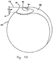
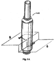
- Figs. 1A-1D illustrates aspects of a separation system.
- Separation system 100 includes vessel 105, which may be any structure sufficient to contain fluid within.
- vessel 105 is cylindrical.
- vessel 105 may be any cross-sectional shape, e.g., rectangular, circular and/or the like.
- vessel 105 may be any size sufficient to accommodate the flow of fluid discharged from a reactor system during shut-down, for example, the volume of the vessel may be 10-15 m 3 .
- vessel 105 is substantially vertically oriented and defined by central vertical axis Z. In other embodiments, vessel 105 may be substantially horizontally oriented or in another orientation.
- Vessel 105 may be made of any suitable material, such as steel.
- Vessel 105 includes fluid inlets 110, 112. Two fluid inlets are shown; however separation system 100 may include any number of fluid inlets greater than one and sufficient to deliver fluid into vessel 105.
- Fluid inlets 110, 112 penetrate surface 102 of vessel 105.
- Fluid inlets 110, 112 are preferably defined on surface 102, but may also be configured to extend within vessel 105.
- Fluid inlets 110, 112 may introduce fluid into vessel 105 at a desired trajectory.
- fluid inlets 110, 112 introduce fluid substantially tangentially to surface 102 of vessel 105.
- fluid inlets 110, 112 are preferably configured so that neither fluid inlet's respective flow is directed counter to the direction of the other fluid inlet. For example, in Figs.
- fluid inlets 110, 112 introduce fluid into vessel 105 in the same tangential direction about central vertical axis Z.
- fluid inlets 110, 112 may alternatively be configured to introduce fluid at any other desired angle, including perpendicularly away from or toward surface 102.
- Fluid inlets 110, 112 may be configured to introduce fluid originating from a polymerization reactor, for example, a tubular reactor having a volume over 3.0 m 3 or capacity over 250 kta into vessel 105 upon the onset of an emergency shut-down of the reactor.
- a polymerization reactor for example, a tubular reactor having a volume over 3.0 m 3 or capacity over 250 kta into vessel 105 upon the onset of an emergency shut-down of the reactor.
- fluid flows from the reactor through fluid inlets 110, 112.
- the flow increases rapidly to a maximum mass flux within, for example, 5 seconds, and more particularly within 1 second.
- the mass flux may vary greatly, for example between 0 kg/s and 1000 kg/s and more specifically up to a maximum of about 900 kg/s.
- the total fluid mass flux is split between fluid inlets 110, 112.
- the fluid mass flux through the fluid inlets may be equal or different.
- the mass flux of fluid through upper fluid inlet 110 is greater than the mass flux through lower fluid inlet 112.
- All fluid inlets are positioned at different elevations within vessel 105.
- upper fluid inlet 110 is positioned higher in vessel 105 than lower fluid inlet 112.
- Upper fluid inlet 110 may be directly above lower fluid inlet 112, as shown in Figs. 1A-1D .
- upper fluid inlet 110 may be positioned in a different radial position from lower fluid inlet 112 around central vertical axis Z.
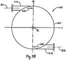
- one fluid inlet may be positioned 180 degrees about central vertical axis Z from another fluid inlet, as shown in Figs. 2A-2B .
- upper fluid inlet 210 is positioned above and 180 degrees around vessel 205 from lower fluid inlet 212.
- Upper fluid stream 211 is introduced through upper fluid inlet 210 while lower fluid stream 213 is introduced through lower fluid inlet 212. Both fluid streams 211 and 213 are directed in the same tangential direction 230 around central vertical axis Z.
- Figs. 1C and 1D illustrate characteristics of fluid flow through fluid inlets 110, 112 during peak or near peak mass flux conditions.
- fluid streams 111, 113 may experience sonic conditions before reaching fluid inlets 110, 112 and may expand upon entering vessel 105 at surface 102. Expanding fluid jets may form in these areas, marked by regions of supersonic flow 120 where M (Mach number) is much greater than 1, supersonic flow 121 where M is greater than 1, and sonic flow 122 where M ⁇ 1.
- an oblique shock 124 may form, as shown in Fig. ID.
- the distance between fluid inlets 110 and 112 is sufficient that the expanding fluid jet from each fluid inlet does not interfere with the other, as shown in Fig. 1C .
- the vertical distance between fluid inlets 110 and 112 may be a distance of at least 1.5 ⁇ D I in order to avoid jet interaction.
- the vertical distance between fluid inlets 110 and 112 may be a distance of at least 1.5 ⁇ (D 1 + D 2 )/2 in order to avoid jet interaction.
- the fluid may be any composition containing particles, whether in solid, gas, or aqueous form.
- the fluid may comprise any known or hereinafter devised polymerization reaction components in the gas phase (e.g., one or more of olefin monomers such as ethylene-derived units or propylene-derived units, comonomers such as ⁇ -olefins, solvents, initiators, catalysts, additives, hydrogen, and/or the like) in combination with one or more particles (e.g., polymers such as those containing ethylene-derived units or propylene-derived units) suspended therein (e.g., a polyolefin, such as polyethylene or polypropylene).
- olefin monomers such as ethylene-derived units or propylene-derived units
- comonomers such as ⁇ -olefins
- solvents e.g., initiators, catalysts, additives, hydrogen, and/or the like
- particles e.g., polymers such as
- Separation system 100 further includes a reservoir within vessel 105 containing a coolant 185.
- the bottom of vessel 105 may comprise opening 104 or one or more nozzles that may be located on the side of the vessel to permit entry or exit of coolant 185.
- Coolant 185 is a liquid, preferably water, and may be relatively cool compared to the fluid (e.g., about 5 °C to about 40 °C). Coolant 185 serves multiple useful purposes. First, after the fluid is introduced to vessel 105, coolant 185 serves to quench the fluid upon contact, causing solid polymer particles to precipitate out from the fluid.
- Coolant 185 may be filled to a desired level, as long as the level is maintained below lower fluid inlet 112. The coolant level may be maintained and monitored using appropriate level devices via nozzles inside of vessel 105. Coolant 185 may be drained from the vessel and/or may undergo further processing to remove the particles. The reservoir may be recharged with additional coolant.
- Vessel 105 includes a fluid outlet 115 sufficient to discharge the fluid/coolant mixture from the vessel.
- Fluid outlet 115 is preferably be located at the top of vessel 105 concentric with central vertical axis Z to facilitate substantially vertical fluid discharge.
- Fluid outlet 115 may also comprise a vertical stack that guides the discharged fluid/coolant into the atmosphere.
- the internal diameters of fluid inlets 110, 112 and fluid outlet 115 may be sized to control the speed and/or pressure of entry and/or exit of the fluid.
- the internal diameter of the fluid inlets may be relatively small (e.g., about 0.04 to about 0.3 m) and/or the internal diameter of the fluid outlet may be relatively large (e.g., about 0.5 to about 1.5 m).
- P V M 0 ⁇ 1 + ⁇ ⁇ e ⁇ t / ⁇ ⁇ c / 0.73 ⁇ A OUTLET ;
- a OUTLET is the area of fluid outlet 115, calculated as ⁇ ⁇ D O 2 / 4 where D O is the internal diameter of fluid outlet 115 in the instance that the fluid outlet is circular.
- the Swirl Factor is a fitting coefficient based on empirical evidence and is affected by the specific arrangement of fluid inlets 110, 112 and fluid outlet 115.
- the internal diameter of fluid outlet 115 has a compound effect on internal surface pressure, which determines the dynamic forces and moments acting on vessel 105.
- the minimum diameter of fluid outlet 115 may be determined based on the maximum internal surface pressure limits of the vessel which may be based on other design requirements.
- Separation system 100 may further include barrier 180 to prevent fluid from prematurely exiting the system. As fluid swirls in vessel 105 and rises toward fluid outlet 115, barrier 180 forces the fluid downward to prevent premature exit of fluid and promote further separation of particles.
- fluid streams 111 and 113 enter separation system 100 through fluid inlets 110 and 112 respectively at an angle substantially tangential to wall 102 of vessel 105.
- the fluid streams immediately begin to swirl inside vessel 105, creating a vortex.
- the high momentum fluid flow interacts with coolant 185, pulverizing a portion of the coolant into fine droplets and causing the liquid mass to swirl.
- the atomized coolant suppresses build-up of static charge, lowers the temperature of the fluid/coolant mixture, and prevents potential ignition of the fluid.
- One or more separation systems may be employed in parallel or in series to further control and reduce the amount of polymer released into the atmosphere.
- the invention also relates to a polymerization system including a reactor and separation system.
- the reactor may be a high pressure polymerization reactor, for example, a tubular, autoclave or slurry loop reactor, or combination thereof.
- polymerization system 300 includes separation system 301 and reactor 350.
- Reactor 350 may be a tubular reactor with multiple zones including an upstream end 352, a downstream end 354, and a midstream zone 353 between the upstream and downstream ends.
- the polymerization system 300 may further include any number of additional components to facilitate the polymerization process (e.g., compressors 382, separators 390, and dryers 392).
- feed stream 378 comprising an olefin monomer along with component(s) needed for polymerization, e.g., initiators, catalysts and/or the like, and optionally, one or more components that are polymerizable therewith, e.g., a comonomer, is supplied directly or via optional compressor 382 to upstream end 352 of reactor 350.
- the olefin monomer may be ethylene or propylene, for example.
- Possible initiators include but are not limited to peroxides.
- Suitable catalysts include, but are not limited to, Ziegler/Natta catalysts or other single site catalysts.
- Feed stream 378 enters reactor 350 to form polymer 395 (e.g., polyethylene or polypropylene) which exits reactor 350 at downstream end 354.
- Reactor 350 may have a volume over 3.0 m 3 or capacity over 250 kta and operate at a pressure of about 120 to about 310 MPa, or about 200 to 250 MPa and at a temperature of about 225 to about 375 °C, or about 250 to 350 °C.
- reactor 350 In the event reactor 350 needs to be shut down, e.g., it exceeds a predetermined pressure or temperature, feed stream 378 may be stopped and the pressure within reactor 350 be let down by opening two or more valves 388, 389 which transfer reaction mixture comprising a mixture of gas and polymer particles in fluid streams 311 and 313 to separation system 301.
- opening valves includes manual opening as well as automatic actuation and the like.
- Fluid stream 311 may originate from a specific zone of reactor 350, for example, the midstream zone. Fluid stream 313 may originate from a different zone of reactor 350 than fluid stream 311, for example downstream end 354. By having multiple valves and fluid streams exiting from different zones of the reactor, the reactor may be let down quicker and emergency shut-down be accomplished safely.
- Reactor 350 particularly as a tubular reactor, may have a pressure step-down gradient from upstream end 352 to downstream end 354. The midstream zone may therefore be more highly pressurized than downstream end 354 causing a higher mass flux through fluid stream 311 than through fluid stream 313.
- Fluid stream 311 may be delivered to separation system 301 through an upper fluid inlet while fluid stream 313 may be delivered to separation system 301 through a lower fluid inlet. Based on the origin reactor zone of fluid stream 311 and 313, the mass flux through the upper fluid inlet may be higher than the mass flux through the lower fluid inlet.
- the reaction mixture Upon introduction into separation system 301, the reaction mixture swirls in the separation system vessel, combining with a separation system liquid contained in the vessel which separates the polymer particles out before releasing fluid 303 into the atmosphere. Residual polymer 394 can then be removed from separation system 301.
- polymerization system 400 includes separation system 401 and reactor 450.
- reactor 450 may be an autoclave reactor.
- Reactor 450 may have a capacity over 100 kta.
- the polymerization system 400 may further include any number of additional components to facilitate the polymerization process as disclosed above with regard to polymerization system 300.
- Reactor 450 may be let down by opening one or more valves 489 which transfer reaction mixture comprising a mixture of gas and polymer particles in fluid stream 413 to separation system 401.
- Polymerization system may also include one or more automatic pressure relief devices 486, 487, 488.
- Pressure relief devices 486, 487, 488 may be any recloseable or non-recloseable devices that allow fluid flow at a predetermined pressure, including, but not limited to, rupture discs, bursting caps and automatic relief valves.
- One or more pressure relief devices 487, 488 may transfer reaction mixture in fluid streams 411, 412 to separation system 401.
- Separation system 401 functions as described above with regard to separation system 301, with fluid streams 411 and 413 delivered to separation system 401 through upper and lower fluid inlets, separated fluid 403 released to atmosphere, and residual polymer 494 subsequently removed.
- fluid streams 411, 412, 413 are delivered to separation system 401, such as illustrated in Fig. 4 , all fluid streams are delivered through fluid inlets at different heights sufficient that the expanding fluid jet from each fluid inlet does not interfere with the others as explained above in reference to Fig. 1C .
- the vertical distance between fluid inlets may be a distance of at least 1.5 ⁇ D I in order to avoid jet interaction.
- Fluid inlets for fluid streams 411, 412, 413 may all be vertically aligned, or may be positioned in any combination of rotation about central vertical axis Z of separation system 401.
- Polymerization system 400 may also comprise one or more additional pressure relief devices 486 that release fluid directly to the atmosphere.
- Pressure relief devices 486, 487, 489 may be set to activate at different pressures.
- pressure relief devices 487, 488 which let down to separation system 401 may be set at a lower relief pressure than pressure relief device 486 which lets down to the atmosphere.
- pressure relief devices 486, 487 and 488 may provide redundant safety systems to depressurize reactor 450.
- pressure relief devices 487, 488 may be set to activate upon the same triggering event that opens valve 489, thereby allowing simultaneous and expedient let down of reactor 450 through fluid streams 411, 412 and 413.
- the invention also relates to a process for shutting down a polymerization system (e.g., emergency shut down due to excess pressure and/or temperature).
- the process may include letting down polymerization reactor 350 by opening two or more valves 388, 389.
- the process may also include discharging the reaction mixture from polymerization reactor 350, which may be, for example, a high-pressure polymerization reactor, to separation system 301, wherein separation system 301 includes a vessel with at least two fluid inlets including a first fluid inlet and a second fluid inlet, a fluid outlet, and a reservoir configured to contain a liquid at a variable level.
- the first fluid inlet is positioned higher in the vessel than the second fluid inlet which is in turn positioned higher in the vessel than the level of liquid.
- the method may also include discharging a portion of the reaction mixture from a point between an upstream end and a downstream end of the polymerization reactor to the separation system through the first fluid inlet and discharging a portion of the reaction mixture from the downstream end of the polymerization reactor to the separation system through the second fluid inlet.
- the method may also include discharging a higher mass flux of reaction mixture through the first fluid inlet into the vessel than through the second fluid inlet.
- a Computational Fluid Dynamics (“CFD”) model was developed to simulate an example separation system under reactor shut-down conditions.
- the modelled system is 12.08 m 3 including a cylindrical vessel with an internal diameter of 2040 mm and a vertical fluid outlet with a diameter of 895.25 mm.
- the separation system includes two fluid inlets defined in the inner cylindrical surface of the vessel, one fluid inlet directly above the other, configured to direct fluid flow tangentially along the inner surface in a counter clockwise direction.
- the level of liquid in the vessel is 200 mm below the lower fluid inlet.
- the model is based on certain initial boundary conditions for both the input and output of the separation system.
- initial conditions are modelled using a theoretical inlet reservoir in the shape of a rectangular cuboid.
- the upstream face of the inlet reservoir is set as the inlet face, at which the initial boundary conditions are set, while the other faces of the reservoir are modelled as slip walls.
- the boundary conditions represent stagnation conditions upstream of the fluid inlet.
- the boundary conditions for the fluid outlet are modelled using a theoretical outlet reservoir.
- the outlet reservoir represents the atmosphere and is modelled as a very large rectangular cuboid.
- the faces of the outlet reservoir are set at ambient conditions, but are far enough away from the fluid outlet so as not to influence the flow characteristics.
- the coolant surface is only allowed to move as a solid, non-deformable body due to the swirling fluid shearing on it.
- the specific heat ratio of the fluid is 1.24 to model ethylene gas.
- Example 2 had the same conditions as Example 1 with several exceptions:
- the fluid inlets were positioned 180 degrees from each other about the central vertical axis of the vessel.
- the lower fluid inlet was configured to deliver 360 kg/s while the upper fluid inlet was configured to deliver 520 kg/s.
- the fluid outlet diameter was increased to approximately 1016 mm. Under these conditions, a generally subsonic circular flow developed within the vessel, with a steady flow and expansion jet at the fluid outlet.
- the separation system experienced localized wall pressures in the order of 4 bars at the fluid outlet, 22 bars at the inner surface of the vessel, and up to 40 bars near the fluid inlets.
- Example 3 had the same conditions as Example 2 except that the fluid inlets were placed on the same vertical level. Under these conditions, a generally supersonic circular flow developed within the vessel, with an unsteady flow through the fluid outlet.
- the separation system experienced localized wall pressures in the order of 5 bars at the fluid outlet, 37 bars at the inner surface of the vessel, and up to 50 bars near the fluid inlets.
Landscapes
- Chemical & Material Sciences (AREA)
- Chemical Kinetics & Catalysis (AREA)
- Organic Chemistry (AREA)
- Physics & Mathematics (AREA)
- Fluid Mechanics (AREA)
- Health & Medical Sciences (AREA)
- Medicinal Chemistry (AREA)
- Polymers & Plastics (AREA)
- Polymerisation Methods In General (AREA)
- Devices And Processes Conducted In The Presence Of Fluids And Solid Particles (AREA)
Claims (8)
- Polymerisationssystem, das umfasst:einen rohrförmigen Polymerisationsreaktor undein Trennsystem (100), das umfasst:ein im Wesentlichen zylindrisches Gefäß (105), das um eine zentrale, vertikale Achse (Z) definiert ist und eine Gefäßinnenoberfläche (102), mindestens zwei Fluideinlässe (110, 112), die einen ersten Fluideinlass (110) und einen zweiten Fluideinlass (112) einschließen, einen Fluidauslass (115) und ein Reservoir, das konfiguriert ist, ein Kühlmittel (185) in einem variablen Niveau zu enthalten, umfasst, wobei der erste Fluideinlass (110) höher in dem Gefäß positioniert ist als der zweite Fluideinlass (112) und der zweite Fluideinlass höher in dem Gefäß positioniert ist als das Niveau des Kühlmittels (185) ist, das in dem Reservoir enthalten ist,wobei die Fluideinlässe (110,112) mit dem Polymerisationsreaktor verbunden sind und jeder Fluideinlass (110,112) konfiguriert ist, Fluid aus einer unterschiedlichen Zone des Polymerisationsreaktors zu dem Gefäß (105) zu liefern,wobei der Polymerisationsreaktor Zonen umfasst, die ein stromaufwärtiges Ende, ein stromabwärtiges Ende und eine Zone in der Mitte des Stroms umfasst, die zwischen dem stromaufwärtigen Ende und dem stromabwärtigen Ende angeordnet ist,wobei der erste Fluidauslass (110) konfiguriert ist, Fluid aus der Zone in der Mitte des Stroms zu dem Gefäß (105) zu liefern, und der zweite Fluideinlass (112) konfiguriert ist, Fluid vom stromabwärtigen Ende zu dem Gefäß (105) zu liefern,wobei der erste Fluidstrom (110) konfiguriert ist, einen größeren Massefluss von Fluid zu dem Gefäß zu liefern als der zweite Fluideinlass (112), undwobei die Fluideinlässe (110, 112) konfiguriert sind, Fluid im Wesentlichen tangential zu der Gefäßinnenoberfläche (102) in das Gefäß (105) einzuführen.
- Polymerisationssystem nach Anspruch 1, bei dem der rohrförmige Polymerisationsreaktor ein Volumen über 3,0 m3 oder eine Kapazität über 250 kta aufweist und bei etwa 120 bis etwa 310 MPa und etwa 225 bis etwa 375°C betreibbar ist.
- Polymerisationssystem nach Anspruch 1, bei dem der erste Fluideinlass direkt über dem zweiten Fluideinlass positioniert ist.
- Polymerisationssystem nach Anspruch 1, bei dem der erste Fluideinlass im Wesentlichen 180 Grad um die zentrale, vertikale Achse von dem zweiten Fluideinlass positioniert ist.
- Verfahren zur Abtrennung von Teilchen aus einer Reaktionsmischung während des Außer-Betrieb-Zustandes (shut-down) eines Polymerisationsreaktors mit einem Volumen über 3.0 m3 oder einer Kapazität über 250 kta, das umfasst:Herunterfahren des Polymerisationsreaktors durch Öffnen eines oder mehrerer Ventile, undAbführen mindestens eines Teils der Reaktionsmischung aus dem Polymerisationsreaktor zu einem Trennsystem, wobei das Trennsystem umfasst:ein im Wesentlichen zylindrisches Gefäß (105), das um eine zentrale, vertikale Achse (Z) definiert ist und eine Gefäßinnenoberfläche (102), mindestens zwei Fluideinlässe (110, 112), die einen ersten Fluideinlass (110) und einen zweiten Fluideinlass (112) einschließen, einen Fluidauslass (115) und ein Reservoir, das konfiguriert ist, ein Kühlmittel (185) in einem variablen Niveau zu enthalten, umfasst, wobei der erste Fluideinlass (110) höher in dem Gefäß positioniert ist als der zweite Fluideinlass (112) und der zweite Fluideinlass höher in dem Gefäß positioniert ist als das Niveau des Kühlmittels (185) ist, das in dem Reservoir enthalten ist,wobei mindestens ein Teil der Reaktionsmischung von einem Punkt zwischen einem stromaufwärtigen Ende und einem stromabwärtigen Ende des Polymerisationsreaktors zu dem Trennsystem durch den ersten Fluideinlass (110) abgeführt wird, und mindestens ein Teil der Reaktionsmischung vom stromabwärtigen Ende des Polymerisationsreaktors zu dem Trennsystem durch den zweiten Fluideinlass (112) abgeführt wird,wobei ein größerer Massenfluss an Reaktionsmischung durch den ersten Fluidauslass (110) in das Gefäß (105) abgeführt wird als durch den zweiten Fluideinlass (112), undwobei die Fluideinlässe (110, 112) konfiguriert sind, Fluid im Wesentlichen tangential zu der Gefäßinnenoberfläche (102) in das Gefäß (105) einzuführen.
- Verfahren nach Anspruch 5, bei dem der Polymerisationsreaktor ein Hochdruckpolymerisationsreaktor ist.
- Verfahren nach Anspruch 6, bei dem der erste Fluideinlass direkt über dem zweiten Fluideinlass positioniert ist.
- Verfahren nach Anspruch 6, bei dem der erste Fuideinlass im Wesentlichen 180 Grad um die zentrale, vertikale Achse von dem zweiten Fluideinlass positioniert ist.
Applications Claiming Priority (3)
| Application Number | Priority Date | Filing Date | Title |
|---|---|---|---|
| US201461934075P | 2014-01-31 | 2014-01-31 | |
| EP14163817 | 2014-04-08 | ||
| PCT/IB2014/003192 WO2015114401A1 (en) | 2014-01-31 | 2014-12-16 | Fluid separation systems and methods |
Publications (2)
| Publication Number | Publication Date |
|---|---|
| EP3099396A1 EP3099396A1 (de) | 2016-12-07 |
| EP3099396B1 true EP3099396B1 (de) | 2020-04-22 |
Family
ID=50439280
Family Applications (1)
| Application Number | Title | Priority Date | Filing Date |
|---|---|---|---|
| EP14880887.6A Active EP3099396B1 (de) | 2014-01-31 | 2014-12-16 | Fluidtrennsysteme und -verfahren |
Country Status (6)
| Country | Link |
|---|---|
| US (1) | US9821252B2 (de) |
| EP (1) | EP3099396B1 (de) |
| KR (1) | KR101860656B1 (de) |
| CN (1) | CN105939771B (de) |
| MY (1) | MY190683A (de) |
| WO (1) | WO2015114401A1 (de) |
Families Citing this family (5)
| Publication number | Priority date | Publication date | Assignee | Title |
|---|---|---|---|---|
| CN109332020A (zh) * | 2018-11-14 | 2019-02-15 | 武汉工程大学 | 一种介入式旋流分离器 |
| CN112390261A (zh) * | 2019-08-13 | 2021-02-23 | 斯特里特技术有限公司 | 气相二氧化硅颗粒分离脱氢的系统和方法 |
| EP3831472A1 (de) * | 2019-12-03 | 2021-06-09 | Basell Polyolefine GmbH | Hochdruckpolymerisationssystem und hochdruckpolymerisationsverfahren zur polymerisation von ethylenisch ungesättigten monomeren |
| US12053786B2 (en) | 2020-07-03 | 2024-08-06 | Valmet Technologies Oy | Hydrocyclone with an improved fluid injection member |
| CN115449412B (zh) * | 2022-08-29 | 2025-08-01 | 甘肃蓝科石化高新装备股份有限公司 | 一种芯体一体化可拆型超音速分离器 |
Family Cites Families (10)
| Publication number | Priority date | Publication date | Assignee | Title |
|---|---|---|---|---|
| DE2631834C3 (de) | 1976-07-15 | 1980-05-14 | Basf Ag, 6700 Ludwigshafen | Verfahren zur Entspannung von Äthylen-Hochdruckpolymerisationssystemen |
| CN1011861B (zh) * | 1984-08-24 | 1991-03-06 | 联合碳化公司 | 流化床聚合反应器的改进 |
| DE3641513A1 (de) | 1986-12-04 | 1988-06-09 | Basf Ag | Verfahren zur reduktion der emission von kohlenwasserstoffen bei entspannungsvorgaengen an hochdruckpolymerisationsreaktoren |
| KR20010014570A (ko) * | 1999-04-23 | 2001-02-26 | 구자홍 | 싸이클론 집진장치의 압력손실 저감 장치 |
| DE10016625A1 (de) * | 2000-04-04 | 2001-10-11 | Basell Polyolefine Gmbh | Gasphasenpolymerisationsverfahren mit Direktkühlsystem |
| US6673878B2 (en) * | 2001-12-19 | 2004-01-06 | Exxonmobil Chemical Patents Inc. | Tubular polymerization reactors and polymers made therein |
| US7714083B2 (en) * | 2006-03-08 | 2010-05-11 | Exxonmobil Chemical Patents Inc. | Recycle of hydrocarbon gases from the product tanks to a reactor through the use of ejectors |
| US7910637B2 (en) * | 2007-09-13 | 2011-03-22 | Exxonmobil Research And Engineering Company | In-line blending of plasticizers with a base polymer |
| WO2009071414A1 (en) * | 2007-12-06 | 2009-06-11 | Basell Poliolefine Italia S.R.L. | Method and apparatus for gas-solid separation, application to polymerization reactions |
| EP2498895A1 (de) | 2009-11-13 | 2012-09-19 | ExxonMobil Chemical Patents Inc. | System und verfahren zur flüssigkeitstrennung |
-
2014
- 2014-12-16 MY MYPI2016702461A patent/MY190683A/en unknown
- 2014-12-16 WO PCT/IB2014/003192 patent/WO2015114401A1/en not_active Ceased
- 2014-12-16 EP EP14880887.6A patent/EP3099396B1/de active Active
- 2014-12-16 US US15/105,806 patent/US9821252B2/en active Active
- 2014-12-16 KR KR1020167020097A patent/KR101860656B1/ko active Active
- 2014-12-16 CN CN201480074315.9A patent/CN105939771B/zh active Active
Non-Patent Citations (1)
| Title |
|---|
| None * |
Also Published As
| Publication number | Publication date |
|---|---|
| CN105939771B (zh) | 2019-08-06 |
| US9821252B2 (en) | 2017-11-21 |
| WO2015114401A9 (en) | 2016-06-09 |
| KR20160102520A (ko) | 2016-08-30 |
| EP3099396A1 (de) | 2016-12-07 |
| KR101860656B1 (ko) | 2018-05-23 |
| CN105939771A (zh) | 2016-09-14 |
| MY190683A (en) | 2022-05-10 |
| US20160332094A1 (en) | 2016-11-17 |
| WO2015114401A1 (en) | 2015-08-06 |
Similar Documents
| Publication | Publication Date | Title |
|---|---|---|
| EP3099396B1 (de) | Fluidtrennsysteme und -verfahren | |
| US4613484A (en) | Loop reactor settling leg system for separation of solid polymers and liquid diluent | |
| KR101493531B1 (ko) | 폴리에틸렌 및 에틸렌 공중합체의 제조 장치 | |
| CN107223137B (zh) | 烯属不饱和单体的高压聚合方法 | |
| KR101671043B1 (ko) | 퍼옥시드 개시제 주입용 저밀도 폴리에틸렌(ldpe) 관형 반응기 | |
| EA026846B1 (ru) | Гибкая реакторная установка для полимеризации олефинов | |
| JP5410430B2 (ja) | 改良された製品取出し手段を有するオレフィン重合に適したループ反応装置 | |
| JP2007532722A (ja) | 垂直回転流動床を用いた触媒重合方法 | |
| WO2002062857A1 (en) | Processing using condensing mode in fluidized beds, with liquid phase enrichment and bed injection | |
| JPH0699490B2 (ja) | 懸濁重合方法及び懸濁重合装置 | |
| CN114746169B (zh) | 用于烯属不饱和单体聚合的高压聚合系统和高压聚合方法 | |
| US20210179746A1 (en) | Polymerization of Propylene | |
| CN102639207B (zh) | 流体分离系统和方法 | |
| CN111714934A (zh) | 减少气液夹带现象的超压泄放装置及多相反应系统 | |
| EP2590735B1 (de) | Sperre und verfahren | |
| CN111714933A (zh) | 减少多相反应器物料喷溅的超压泄放装置及多相反应系统 | |
| JPH0543620A (ja) | 高圧法ポリエチレン製造装置用ガス放出装置 | |
| CN111715145A (zh) | 减少固相喷料的超压泄放装置及多相反应系统 | |
| KR101909718B1 (ko) | 미세 기체 방울 발생 장치 | |
| NO118483B (de) | ||
| JPS5919572B2 (ja) | 高圧重合エチレン系緊急時放出ガスの着火を防止する方法とその装置 | |
| AU2002243855A1 (en) | Processing using condensing mode in fluidized beds, with liquid phase enrichment and bed injection |
Legal Events
| Date | Code | Title | Description |
|---|---|---|---|
| PUAI | Public reference made under article 153(3) epc to a published international application that has entered the european phase |
Free format text: ORIGINAL CODE: 0009012 |
|
| STAA | Information on the status of an ep patent application or granted ep patent |
Free format text: STATUS: REQUEST FOR EXAMINATION WAS MADE |
|
| 17P | Request for examination filed |
Effective date: 20160830 |
|
| AK | Designated contracting states |
Kind code of ref document: A1 Designated state(s): AL AT BE BG CH CY CZ DE DK EE ES FI FR GB GR HR HU IE IS IT LI LT LU LV MC MK MT NL NO PL PT RO RS SE SI SK SM TR |
|
| AX | Request for extension of the european patent |
Extension state: BA ME |
|
| DAX | Request for extension of the european patent (deleted) | ||
| STAA | Information on the status of an ep patent application or granted ep patent |
Free format text: STATUS: EXAMINATION IS IN PROGRESS |
|
| 17Q | First examination report despatched |
Effective date: 20190412 |
|
| GRAP | Despatch of communication of intention to grant a patent |
Free format text: ORIGINAL CODE: EPIDOSNIGR1 |
|
| STAA | Information on the status of an ep patent application or granted ep patent |
Free format text: STATUS: GRANT OF PATENT IS INTENDED |
|
| INTG | Intention to grant announced |
Effective date: 20191127 |
|
| GRAS | Grant fee paid |
Free format text: ORIGINAL CODE: EPIDOSNIGR3 |
|
| GRAA | (expected) grant |
Free format text: ORIGINAL CODE: 0009210 |
|
| STAA | Information on the status of an ep patent application or granted ep patent |
Free format text: STATUS: THE PATENT HAS BEEN GRANTED |
|
| AK | Designated contracting states |
Kind code of ref document: B1 Designated state(s): AL AT BE BG CH CY CZ DE DK EE ES FI FR GB GR HR HU IE IS IT LI LT LU LV MC MK MT NL NO PL PT RO RS SE SI SK SM TR |
|
| REG | Reference to a national code |
Ref country code: CH Ref legal event code: EP |
|
| REG | Reference to a national code |
Ref country code: DE Ref legal event code: R096 Ref document number: 602014064312 Country of ref document: DE |
|
| REG | Reference to a national code |
Ref country code: IE Ref legal event code: FG4D |
|
| REG | Reference to a national code |
Ref country code: AT Ref legal event code: REF Ref document number: 1259327 Country of ref document: AT Kind code of ref document: T Effective date: 20200515 |
|
| REG | Reference to a national code |
Ref country code: LT Ref legal event code: MG4D |
|
| REG | Reference to a national code |
Ref country code: NL Ref legal event code: MP Effective date: 20200422 |
|
| PG25 | Lapsed in a contracting state [announced via postgrant information from national office to epo] |
Ref country code: GR Free format text: LAPSE BECAUSE OF FAILURE TO SUBMIT A TRANSLATION OF THE DESCRIPTION OR TO PAY THE FEE WITHIN THE PRESCRIBED TIME-LIMIT Effective date: 20200723 Ref country code: NO Free format text: LAPSE BECAUSE OF FAILURE TO SUBMIT A TRANSLATION OF THE DESCRIPTION OR TO PAY THE FEE WITHIN THE PRESCRIBED TIME-LIMIT Effective date: 20200722 Ref country code: IS Free format text: LAPSE BECAUSE OF FAILURE TO SUBMIT A TRANSLATION OF THE DESCRIPTION OR TO PAY THE FEE WITHIN THE PRESCRIBED TIME-LIMIT Effective date: 20200822 Ref country code: SE Free format text: LAPSE BECAUSE OF FAILURE TO SUBMIT A TRANSLATION OF THE DESCRIPTION OR TO PAY THE FEE WITHIN THE PRESCRIBED TIME-LIMIT Effective date: 20200422 Ref country code: FI Free format text: LAPSE BECAUSE OF FAILURE TO SUBMIT A TRANSLATION OF THE DESCRIPTION OR TO PAY THE FEE WITHIN THE PRESCRIBED TIME-LIMIT Effective date: 20200422 Ref country code: NL Free format text: LAPSE BECAUSE OF FAILURE TO SUBMIT A TRANSLATION OF THE DESCRIPTION OR TO PAY THE FEE WITHIN THE PRESCRIBED TIME-LIMIT Effective date: 20200422 Ref country code: PT Free format text: LAPSE BECAUSE OF FAILURE TO SUBMIT A TRANSLATION OF THE DESCRIPTION OR TO PAY THE FEE WITHIN THE PRESCRIBED TIME-LIMIT Effective date: 20200824 Ref country code: LT Free format text: LAPSE BECAUSE OF FAILURE TO SUBMIT A TRANSLATION OF THE DESCRIPTION OR TO PAY THE FEE WITHIN THE PRESCRIBED TIME-LIMIT Effective date: 20200422 |
|
| REG | Reference to a national code |
Ref country code: AT Ref legal event code: MK05 Ref document number: 1259327 Country of ref document: AT Kind code of ref document: T Effective date: 20200422 |
|
| PG25 | Lapsed in a contracting state [announced via postgrant information from national office to epo] |
Ref country code: LV Free format text: LAPSE BECAUSE OF FAILURE TO SUBMIT A TRANSLATION OF THE DESCRIPTION OR TO PAY THE FEE WITHIN THE PRESCRIBED TIME-LIMIT Effective date: 20200422 Ref country code: BG Free format text: LAPSE BECAUSE OF FAILURE TO SUBMIT A TRANSLATION OF THE DESCRIPTION OR TO PAY THE FEE WITHIN THE PRESCRIBED TIME-LIMIT Effective date: 20200722 Ref country code: RS Free format text: LAPSE BECAUSE OF FAILURE TO SUBMIT A TRANSLATION OF THE DESCRIPTION OR TO PAY THE FEE WITHIN THE PRESCRIBED TIME-LIMIT Effective date: 20200422 Ref country code: HR Free format text: LAPSE BECAUSE OF FAILURE TO SUBMIT A TRANSLATION OF THE DESCRIPTION OR TO PAY THE FEE WITHIN THE PRESCRIBED TIME-LIMIT Effective date: 20200422 |
|
| PG25 | Lapsed in a contracting state [announced via postgrant information from national office to epo] |
Ref country code: AL Free format text: LAPSE BECAUSE OF FAILURE TO SUBMIT A TRANSLATION OF THE DESCRIPTION OR TO PAY THE FEE WITHIN THE PRESCRIBED TIME-LIMIT Effective date: 20200422 |
|
| REG | Reference to a national code |
Ref country code: DE Ref legal event code: R097 Ref document number: 602014064312 Country of ref document: DE |
|
| PG25 | Lapsed in a contracting state [announced via postgrant information from national office to epo] |
Ref country code: DK Free format text: LAPSE BECAUSE OF FAILURE TO SUBMIT A TRANSLATION OF THE DESCRIPTION OR TO PAY THE FEE WITHIN THE PRESCRIBED TIME-LIMIT Effective date: 20200422 Ref country code: SM Free format text: LAPSE BECAUSE OF FAILURE TO SUBMIT A TRANSLATION OF THE DESCRIPTION OR TO PAY THE FEE WITHIN THE PRESCRIBED TIME-LIMIT Effective date: 20200422 Ref country code: EE Free format text: LAPSE BECAUSE OF FAILURE TO SUBMIT A TRANSLATION OF THE DESCRIPTION OR TO PAY THE FEE WITHIN THE PRESCRIBED TIME-LIMIT Effective date: 20200422 Ref country code: AT Free format text: LAPSE BECAUSE OF FAILURE TO SUBMIT A TRANSLATION OF THE DESCRIPTION OR TO PAY THE FEE WITHIN THE PRESCRIBED TIME-LIMIT Effective date: 20200422 Ref country code: IT Free format text: LAPSE BECAUSE OF FAILURE TO SUBMIT A TRANSLATION OF THE DESCRIPTION OR TO PAY THE FEE WITHIN THE PRESCRIBED TIME-LIMIT Effective date: 20200422 Ref country code: RO Free format text: LAPSE BECAUSE OF FAILURE TO SUBMIT A TRANSLATION OF THE DESCRIPTION OR TO PAY THE FEE WITHIN THE PRESCRIBED TIME-LIMIT Effective date: 20200422 Ref country code: ES Free format text: LAPSE BECAUSE OF FAILURE TO SUBMIT A TRANSLATION OF THE DESCRIPTION OR TO PAY THE FEE WITHIN THE PRESCRIBED TIME-LIMIT Effective date: 20200422 Ref country code: CZ Free format text: LAPSE BECAUSE OF FAILURE TO SUBMIT A TRANSLATION OF THE DESCRIPTION OR TO PAY THE FEE WITHIN THE PRESCRIBED TIME-LIMIT Effective date: 20200422 |
|
| PG25 | Lapsed in a contracting state [announced via postgrant information from national office to epo] |
Ref country code: PL Free format text: LAPSE BECAUSE OF FAILURE TO SUBMIT A TRANSLATION OF THE DESCRIPTION OR TO PAY THE FEE WITHIN THE PRESCRIBED TIME-LIMIT Effective date: 20200422 Ref country code: SK Free format text: LAPSE BECAUSE OF FAILURE TO SUBMIT A TRANSLATION OF THE DESCRIPTION OR TO PAY THE FEE WITHIN THE PRESCRIBED TIME-LIMIT Effective date: 20200422 |
|
| PLBE | No opposition filed within time limit |
Free format text: ORIGINAL CODE: 0009261 |
|
| STAA | Information on the status of an ep patent application or granted ep patent |
Free format text: STATUS: NO OPPOSITION FILED WITHIN TIME LIMIT |
|
| 26N | No opposition filed |
Effective date: 20210125 |
|
| PG25 | Lapsed in a contracting state [announced via postgrant information from national office to epo] |
Ref country code: SI Free format text: LAPSE BECAUSE OF FAILURE TO SUBMIT A TRANSLATION OF THE DESCRIPTION OR TO PAY THE FEE WITHIN THE PRESCRIBED TIME-LIMIT Effective date: 20200422 |
|
| REG | Reference to a national code |
Ref country code: CH Ref legal event code: PL |
|
| PG25 | Lapsed in a contracting state [announced via postgrant information from national office to epo] |
Ref country code: MC Free format text: LAPSE BECAUSE OF FAILURE TO SUBMIT A TRANSLATION OF THE DESCRIPTION OR TO PAY THE FEE WITHIN THE PRESCRIBED TIME-LIMIT Effective date: 20200422 |
|
| REG | Reference to a national code |
Ref country code: BE Ref legal event code: MM Effective date: 20201231 |
|
| PG25 | Lapsed in a contracting state [announced via postgrant information from national office to epo] |
Ref country code: LU Free format text: LAPSE BECAUSE OF NON-PAYMENT OF DUE FEES Effective date: 20201216 Ref country code: IE Free format text: LAPSE BECAUSE OF NON-PAYMENT OF DUE FEES Effective date: 20201216 |
|
| PG25 | Lapsed in a contracting state [announced via postgrant information from national office to epo] |
Ref country code: LI Free format text: LAPSE BECAUSE OF NON-PAYMENT OF DUE FEES Effective date: 20201231 Ref country code: CH Free format text: LAPSE BECAUSE OF NON-PAYMENT OF DUE FEES Effective date: 20201231 |
|
| PG25 | Lapsed in a contracting state [announced via postgrant information from national office to epo] |
Ref country code: TR Free format text: LAPSE BECAUSE OF FAILURE TO SUBMIT A TRANSLATION OF THE DESCRIPTION OR TO PAY THE FEE WITHIN THE PRESCRIBED TIME-LIMIT Effective date: 20200422 Ref country code: MT Free format text: LAPSE BECAUSE OF FAILURE TO SUBMIT A TRANSLATION OF THE DESCRIPTION OR TO PAY THE FEE WITHIN THE PRESCRIBED TIME-LIMIT Effective date: 20200422 Ref country code: CY Free format text: LAPSE BECAUSE OF FAILURE TO SUBMIT A TRANSLATION OF THE DESCRIPTION OR TO PAY THE FEE WITHIN THE PRESCRIBED TIME-LIMIT Effective date: 20200422 |
|
| PG25 | Lapsed in a contracting state [announced via postgrant information from national office to epo] |
Ref country code: MK Free format text: LAPSE BECAUSE OF FAILURE TO SUBMIT A TRANSLATION OF THE DESCRIPTION OR TO PAY THE FEE WITHIN THE PRESCRIBED TIME-LIMIT Effective date: 20200422 |
|
| PG25 | Lapsed in a contracting state [announced via postgrant information from national office to epo] |
Ref country code: BE Free format text: LAPSE BECAUSE OF NON-PAYMENT OF DUE FEES Effective date: 20201231 |
|
| P01 | Opt-out of the competence of the unified patent court (upc) registered |
Effective date: 20230518 |
|
| PGFP | Annual fee paid to national office [announced via postgrant information from national office to epo] |
Ref country code: GB Payment date: 20241217 Year of fee payment: 11 |
|
| PGFP | Annual fee paid to national office [announced via postgrant information from national office to epo] |
Ref country code: FR Payment date: 20241227 Year of fee payment: 11 |
|
| PGFP | Annual fee paid to national office [announced via postgrant information from national office to epo] |
Ref country code: DE Payment date: 20241227 Year of fee payment: 11 |