EP3099362B1 - A device for applying an ophthalmic fluid - Google Patents
A device for applying an ophthalmic fluid Download PDFInfo
- Publication number
- EP3099362B1 EP3099362B1 EP15709623.1A EP15709623A EP3099362B1 EP 3099362 B1 EP3099362 B1 EP 3099362B1 EP 15709623 A EP15709623 A EP 15709623A EP 3099362 B1 EP3099362 B1 EP 3099362B1
- Authority
- EP
- European Patent Office
- Prior art keywords
- fluid
- chamber
- air
- piston
- liquid
- Prior art date
- Legal status (The legal status is an assumption and is not a legal conclusion. Google has not performed a legal analysis and makes no representation as to the accuracy of the status listed.)
- Active
Links
- 239000012530 fluid Substances 0.000 title claims description 130
- 239000007788 liquid Substances 0.000 claims description 84
- 239000003595 mist Substances 0.000 claims description 17
- 230000007246 mechanism Effects 0.000 claims description 15
- 230000002572 peristaltic effect Effects 0.000 claims description 14
- 238000004804 winding Methods 0.000 claims description 8
- 210000000744 eyelid Anatomy 0.000 claims description 7
- 238000004891 communication Methods 0.000 claims description 6
- 238000006073 displacement reaction Methods 0.000 claims description 6
- 210000003128 head Anatomy 0.000 description 19
- 239000000463 material Substances 0.000 description 6
- 238000000034 method Methods 0.000 description 6
- 238000003860 storage Methods 0.000 description 4
- 238000012432 intermediate storage Methods 0.000 description 3
- 208000003556 Dry Eye Syndromes Diseases 0.000 description 2
- 206010013774 Dry eye Diseases 0.000 description 2
- 230000000844 anti-bacterial effect Effects 0.000 description 2
- 238000011109 contamination Methods 0.000 description 2
- 210000004087 cornea Anatomy 0.000 description 2
- 238000007599 discharging Methods 0.000 description 2
- 201000010099 disease Diseases 0.000 description 2
- 208000037265 diseases, disorders, signs and symptoms Diseases 0.000 description 2
- 239000003889 eye drop Substances 0.000 description 2
- 229940012356 eye drops Drugs 0.000 description 2
- 239000002991 molded plastic Substances 0.000 description 2
- 230000002093 peripheral effect Effects 0.000 description 2
- 239000007921 spray Substances 0.000 description 2
- 230000001225 therapeutic effect Effects 0.000 description 2
- 238000011282 treatment Methods 0.000 description 2
- 230000004913 activation Effects 0.000 description 1
- 230000001154 acute effect Effects 0.000 description 1
- 239000003732 agents acting on the eye Substances 0.000 description 1
- 230000001419 dependent effect Effects 0.000 description 1
- 230000008021 deposition Effects 0.000 description 1
- 239000006196 drop Substances 0.000 description 1
- 230000000694 effects Effects 0.000 description 1
- 239000011888 foil Substances 0.000 description 1
- 239000007769 metal material Substances 0.000 description 1
- 229940125702 ophthalmic agent Drugs 0.000 description 1
- 239000004033 plastic Substances 0.000 description 1
- 229920003023 plastic Polymers 0.000 description 1
- 238000002360 preparation method Methods 0.000 description 1
- 239000003755 preservative agent Substances 0.000 description 1
- 230000001681 protective effect Effects 0.000 description 1
- 230000000284 resting effect Effects 0.000 description 1
- 238000003466 welding Methods 0.000 description 1
Images

Classifications
-
- B—PERFORMING OPERATIONS; TRANSPORTING
- B05—SPRAYING OR ATOMISING IN GENERAL; APPLYING FLUENT MATERIALS TO SURFACES, IN GENERAL
- B05B—SPRAYING APPARATUS; ATOMISING APPARATUS; NOZZLES
- B05B7/00—Spraying apparatus for discharge of liquids or other fluent materials from two or more sources, e.g. of liquid and air, of powder and gas
- B05B7/24—Spraying apparatus for discharge of liquids or other fluent materials from two or more sources, e.g. of liquid and air, of powder and gas with means, e.g. a container, for supplying liquid or other fluent material to a discharge device
- B05B7/2402—Apparatus to be carried on or by a person, e.g. by hand; Apparatus comprising containers fixed to the discharge device
- B05B7/2405—Apparatus to be carried on or by a person, e.g. by hand; Apparatus comprising containers fixed to the discharge device using an atomising fluid as carrying fluid for feeding, e.g. by suction or pressure, a carried liquid from the container to the nozzle
- B05B7/2416—Apparatus to be carried on or by a person, e.g. by hand; Apparatus comprising containers fixed to the discharge device using an atomising fluid as carrying fluid for feeding, e.g. by suction or pressure, a carried liquid from the container to the nozzle characterised by the means for producing or supplying the atomising fluid, e.g. air hoses, air pumps, gas containers, compressors, fans, ventilators, their drives
- B05B7/2418—Air pumps actuated by the operator, e.g. manually actuated
-
- A—HUMAN NECESSITIES
- A61—MEDICAL OR VETERINARY SCIENCE; HYGIENE
- A61F—FILTERS IMPLANTABLE INTO BLOOD VESSELS; PROSTHESES; DEVICES PROVIDING PATENCY TO, OR PREVENTING COLLAPSING OF, TUBULAR STRUCTURES OF THE BODY, e.g. STENTS; ORTHOPAEDIC, NURSING OR CONTRACEPTIVE DEVICES; FOMENTATION; TREATMENT OR PROTECTION OF EYES OR EARS; BANDAGES, DRESSINGS OR ABSORBENT PADS; FIRST-AID KITS
- A61F9/00—Methods or devices for treatment of the eyes; Devices for putting-in contact lenses; Devices to correct squinting; Apparatus to guide the blind; Protective devices for the eyes, carried on the body or in the hand
- A61F9/0008—Introducing ophthalmic products into the ocular cavity or retaining products therein
- A61F9/0026—Ophthalmic product dispenser attachments to facilitate positioning near the eye
-
- A—HUMAN NECESSITIES
- A61—MEDICAL OR VETERINARY SCIENCE; HYGIENE
- A61F—FILTERS IMPLANTABLE INTO BLOOD VESSELS; PROSTHESES; DEVICES PROVIDING PATENCY TO, OR PREVENTING COLLAPSING OF, TUBULAR STRUCTURES OF THE BODY, e.g. STENTS; ORTHOPAEDIC, NURSING OR CONTRACEPTIVE DEVICES; FOMENTATION; TREATMENT OR PROTECTION OF EYES OR EARS; BANDAGES, DRESSINGS OR ABSORBENT PADS; FIRST-AID KITS
- A61F9/00—Methods or devices for treatment of the eyes; Devices for putting-in contact lenses; Devices to correct squinting; Apparatus to guide the blind; Protective devices for the eyes, carried on the body or in the hand
- A61F9/0008—Introducing ophthalmic products into the ocular cavity or retaining products therein
-
- A—HUMAN NECESSITIES
- A61—MEDICAL OR VETERINARY SCIENCE; HYGIENE
- A61M—DEVICES FOR INTRODUCING MEDIA INTO, OR ONTO, THE BODY; DEVICES FOR TRANSDUCING BODY MEDIA OR FOR TAKING MEDIA FROM THE BODY; DEVICES FOR PRODUCING OR ENDING SLEEP OR STUPOR
- A61M11/00—Sprayers or atomisers specially adapted for therapeutic purposes
- A61M11/006—Sprayers or atomisers specially adapted for therapeutic purposes operated by applying mechanical pressure to the liquid to be sprayed or atomised
- A61M11/007—Syringe-type or piston-type sprayers or atomisers
-
- B—PERFORMING OPERATIONS; TRANSPORTING
- B05—SPRAYING OR ATOMISING IN GENERAL; APPLYING FLUENT MATERIALS TO SURFACES, IN GENERAL
- B05B—SPRAYING APPARATUS; ATOMISING APPARATUS; NOZZLES
- B05B11/00—Single-unit hand-held apparatus in which flow of contents is produced by the muscular force of the operator at the moment of use
- B05B11/01—Single-unit hand-held apparatus in which flow of contents is produced by the muscular force of the operator at the moment of use characterised by the means producing the flow
- B05B11/10—Pump arrangements for transferring the contents from the container to a pump chamber by a sucking effect and forcing the contents out through the dispensing nozzle
- B05B11/1087—Combination of liquid and air pumps
-
- B—PERFORMING OPERATIONS; TRANSPORTING
- B05—SPRAYING OR ATOMISING IN GENERAL; APPLYING FLUENT MATERIALS TO SURFACES, IN GENERAL
- B05B—SPRAYING APPARATUS; ATOMISING APPARATUS; NOZZLES
- B05B7/00—Spraying apparatus for discharge of liquids or other fluent materials from two or more sources, e.g. of liquid and air, of powder and gas
- B05B7/02—Spray pistols; Apparatus for discharge
- B05B7/04—Spray pistols; Apparatus for discharge with arrangements for mixing liquids or other fluent materials before discharge
- B05B7/0416—Spray pistols; Apparatus for discharge with arrangements for mixing liquids or other fluent materials before discharge with arrangements for mixing one gas and one liquid
- B05B7/0441—Spray pistols; Apparatus for discharge with arrangements for mixing liquids or other fluent materials before discharge with arrangements for mixing one gas and one liquid with one inner conduit of liquid surrounded by an external conduit of gas upstream the mixing chamber
- B05B7/0475—Spray pistols; Apparatus for discharge with arrangements for mixing liquids or other fluent materials before discharge with arrangements for mixing one gas and one liquid with one inner conduit of liquid surrounded by an external conduit of gas upstream the mixing chamber with means for deflecting the peripheral gas flow towards the central liquid flow
-
- B—PERFORMING OPERATIONS; TRANSPORTING
- B05—SPRAYING OR ATOMISING IN GENERAL; APPLYING FLUENT MATERIALS TO SURFACES, IN GENERAL
- B05B—SPRAYING APPARATUS; ATOMISING APPARATUS; NOZZLES
- B05B7/00—Spraying apparatus for discharge of liquids or other fluent materials from two or more sources, e.g. of liquid and air, of powder and gas
- B05B7/24—Spraying apparatus for discharge of liquids or other fluent materials from two or more sources, e.g. of liquid and air, of powder and gas with means, e.g. a container, for supplying liquid or other fluent material to a discharge device
- B05B7/2402—Apparatus to be carried on or by a person, e.g. by hand; Apparatus comprising containers fixed to the discharge device
- B05B7/244—Apparatus to be carried on or by a person, e.g. by hand; Apparatus comprising containers fixed to the discharge device using carrying liquid for feeding, e.g. by suction, pressure or dissolution, a carried liquid from the container to the nozzle
- B05B7/2443—Apparatus to be carried on or by a person, e.g. by hand; Apparatus comprising containers fixed to the discharge device using carrying liquid for feeding, e.g. by suction, pressure or dissolution, a carried liquid from the container to the nozzle the carried liquid and the main stream of carrying liquid being brought together downstream of the container before discharge
-
- B—PERFORMING OPERATIONS; TRANSPORTING
- B05—SPRAYING OR ATOMISING IN GENERAL; APPLYING FLUENT MATERIALS TO SURFACES, IN GENERAL
- B05B—SPRAYING APPARATUS; ATOMISING APPARATUS; NOZZLES
- B05B7/00—Spraying apparatus for discharge of liquids or other fluent materials from two or more sources, e.g. of liquid and air, of powder and gas
- B05B7/24—Spraying apparatus for discharge of liquids or other fluent materials from two or more sources, e.g. of liquid and air, of powder and gas with means, e.g. a container, for supplying liquid or other fluent material to a discharge device
- B05B7/2402—Apparatus to be carried on or by a person, e.g. by hand; Apparatus comprising containers fixed to the discharge device
- B05B7/2464—Apparatus to be carried on or by a person, e.g. by hand; Apparatus comprising containers fixed to the discharge device a liquid being fed by mechanical pumping from the container to the nozzle
-
- B—PERFORMING OPERATIONS; TRANSPORTING
- B05—SPRAYING OR ATOMISING IN GENERAL; APPLYING FLUENT MATERIALS TO SURFACES, IN GENERAL
- B05B—SPRAYING APPARATUS; ATOMISING APPARATUS; NOZZLES
- B05B7/00—Spraying apparatus for discharge of liquids or other fluent materials from two or more sources, e.g. of liquid and air, of powder and gas
- B05B7/24—Spraying apparatus for discharge of liquids or other fluent materials from two or more sources, e.g. of liquid and air, of powder and gas with means, e.g. a container, for supplying liquid or other fluent material to a discharge device
- B05B7/2489—Spraying apparatus for discharge of liquids or other fluent materials from two or more sources, e.g. of liquid and air, of powder and gas with means, e.g. a container, for supplying liquid or other fluent material to a discharge device an atomising fluid, e.g. a gas, being supplied to the discharge device
- B05B7/2491—Spraying apparatus for discharge of liquids or other fluent materials from two or more sources, e.g. of liquid and air, of powder and gas with means, e.g. a container, for supplying liquid or other fluent material to a discharge device an atomising fluid, e.g. a gas, being supplied to the discharge device characterised by the means for producing or supplying the atomising fluid, e.g. air hoses, air pumps, gas containers, compressors, fans, ventilators, their drives
-
- A—HUMAN NECESSITIES
- A61—MEDICAL OR VETERINARY SCIENCE; HYGIENE
- A61M—DEVICES FOR INTRODUCING MEDIA INTO, OR ONTO, THE BODY; DEVICES FOR TRANSDUCING BODY MEDIA OR FOR TAKING MEDIA FROM THE BODY; DEVICES FOR PRODUCING OR ENDING SLEEP OR STUPOR
- A61M11/00—Sprayers or atomisers specially adapted for therapeutic purposes
- A61M11/06—Sprayers or atomisers specially adapted for therapeutic purposes of the injector type
-
- A—HUMAN NECESSITIES
- A61—MEDICAL OR VETERINARY SCIENCE; HYGIENE
- A61M—DEVICES FOR INTRODUCING MEDIA INTO, OR ONTO, THE BODY; DEVICES FOR TRANSDUCING BODY MEDIA OR FOR TAKING MEDIA FROM THE BODY; DEVICES FOR PRODUCING OR ENDING SLEEP OR STUPOR
- A61M2210/00—Anatomical parts of the body
- A61M2210/06—Head
- A61M2210/0612—Eyes
-
- B—PERFORMING OPERATIONS; TRANSPORTING
- B05—SPRAYING OR ATOMISING IN GENERAL; APPLYING FLUENT MATERIALS TO SURFACES, IN GENERAL
- B05B—SPRAYING APPARATUS; ATOMISING APPARATUS; NOZZLES
- B05B7/00—Spraying apparatus for discharge of liquids or other fluent materials from two or more sources, e.g. of liquid and air, of powder and gas
- B05B7/24—Spraying apparatus for discharge of liquids or other fluent materials from two or more sources, e.g. of liquid and air, of powder and gas with means, e.g. a container, for supplying liquid or other fluent material to a discharge device
- B05B7/2402—Apparatus to be carried on or by a person, e.g. by hand; Apparatus comprising containers fixed to the discharge device
- B05B7/2405—Apparatus to be carried on or by a person, e.g. by hand; Apparatus comprising containers fixed to the discharge device using an atomising fluid as carrying fluid for feeding, e.g. by suction or pressure, a carried liquid from the container to the nozzle
- B05B7/2424—Apparatus to be carried on or by a person, e.g. by hand; Apparatus comprising containers fixed to the discharge device using an atomising fluid as carrying fluid for feeding, e.g. by suction or pressure, a carried liquid from the container to the nozzle the carried liquid and the main stream of atomising fluid being brought together downstream of the container before discharge
Definitions
- the present invention relates generally to a device for dispensing a mist of an ophthalmic liquid fluid.
- Such devices are already known and vary in structure and design.
- devices are known that comprise a squeeze bottle squeezed by the user to expel the liquid fluid as a mist.
- US 5,997,518 A teach a device and method for delivering small microliter volumes of liquid preparations to the eye or other body part.
- the device and method propose to apply a gas stream to induce a controlled, preselected volume of liquid into the gas stream and to deliver the liquid in the form of small droplets to the desired site.
- the present invention departs from US 5,997,518 A inter alia in that the device according to the present invention includes a second drive, or a dosage drive/pump, for delivering liquid fluid to a user's eye.
- US 5 997 518 discloses an apparatus for applying therapeutic drops to the eye.
- US 3,934,585 A teach a method and apparatus for applying therapeutic eye drops to the eye by metering a predetermined volume of fluid and rapidly applying a pressure to one end of the metered fluid for forcing the fluid from a nozzle.
- US 2009/043269 A teach a liquid dispensing apparatus including a liquid storage space.
- the device includes a nozzle for dispensing liquid. Fluid is expelled through the nozzle by a movable wall operable to reduce the liquid storage space.
- the apparatus also includes an intermediate storage space having variable volume; the intermediate storage space including a liquid inlet in fluid communication with the liquid storage space for receiving liquid therefrom. A specific amount of the liquid is transferred from the liquid storage space to the intermediate storage space in a single operation.
- US 2002/161344 A teach a device and use method for ejecting a liquid stream towards an eye.
- the device includes a pump mechanism operable to deliver at least part of the liquid from a container through the opening to form a stream of liquid.
- the pump mechanism may include a pump driver able to store cocked energy for driving the pump mechanism and at least one activation mechanism may be present and operable to initiate the device for the liquid delivery, whereby a driving mechanism is arranged to transform manual or stored energy into cocked energy.
- US 2014/213989 A teach a fluid dispenser suitable for ophthalmic treatments and delivering of ophthalmic agents such as eye drops.
- the fluid dispenser incorporates a tube made from compliant materials as the key dosing component.
- a first point and a second point on the tube may be acted upon by folding the tube or by external elements, making the segment between the first point and the second point a squeezing section that houses a dosing chamber.
- the squeezing section may be pressed by an anvil or other structures, pressurizing the fluid contained in the dosing chamber so that once the tube is released on one point, the fluid in the dosing chamber is discharged. With each dosing process, a single dose of the fluid is discharged.
- the fluid dispenser is capable of delivering a series of doses of the fluid by repeating the dosing process.
- the liquid fluid exits the bottle as rather larger droplets and it is difficult if not impossible for the user to dispense an exact dose of the liquid fluid, which may be required where the user is under treatment for an ophthalmic disease or condition, such as dry eyes.
- the present invention seeks to overcome such problems with the prior art dispensers, without compromising the need to provide a simple and user friendly dispenser which allows for repeated discharge of a dose of a medical ophthalmic fluid.
- fine, or relatively fine, droplets are achieved even where a liquid fluid of medium viscosity, such as in the order of 1-100 mPa.s is dispensed, through the action of a dedicated air flow, while according to another aspect a repeated discharge of identical doses is made possible.
- a liquid fluid of medium viscosity such as in the order of 1-100 mPa.s
- a dedicated air flow while according to another aspect a repeated discharge of identical doses is made possible.
- the invention it becomes possible to dispense the ophthalmic liquid fluid irrespectively of the user holding his head upright or tilted, or even if the user is in bed lying down.
- the inventive device comprises a discharge opening, possibly formed by a spray nozzle, for discharging a mist of fluid, a mixing chamber communicating with the discharge opening, an air chamber for holding a volume of air, a first drive operable to expel air from the air chamber, a fluid chamber for holding a volume of the fluid to be dispensed and communicating with the mixing chamber, a second drive for delivering a predetermined dose of the fluid to the fluid chamber and configured for communicating with a supply of the fluid, such as a container, the air chamber communicating with the fluid chamber and separately with the mixing chamber, and the device being configured for establishing one flow of the expelled air flowing into the fluid chamber, so as to drive the said volume of liquid from the fluid chamber into the mixing chamber, and another flow of the said expelled air flowing past the fluid chamber into the mixing chamber, for assisted atomizing of the fluid by the said other flow of air striking the fluid driven into the mixing chamber.
- the device may include a peristaltic pump or similar in fluid connection with the aforementioned fluid chamber. It is also contemplated to include a mechanism allowing for a user to bring the device into a configuration ready for dispensing using a minimum of manual force, which may be required where to device is to be used by eg. an elderly person.
- the device may further comprise a rotatable head or handle, a piston including a rod and a piston head received in a structure, such as a cylinder, defining the air chamber, the rod and the handle including a winding track and a stationary tab slidably received therein therewith, for displacing by rotation of the handle the piston to a retracted position for holding the volume of air in the air chamber, and a lock and release mechanism for locking and releasing the piston in and from the retracted position, for a spring forming the aforementioned first drive to drive the piston towards an advanced position, giving rise to said expelling.
- a rotatable head or handle a piston including a rod and a piston head received in a structure, such as a cylinder, defining the air chamber, the rod and the handle including a winding track and a stationary tab slidably received therein therewith, for displacing by rotation of the handle the piston to a retracted position for holding the volume of air in the air chamber, and
- a high certainty that a uniform dose of the fluid is applied each time is achievable even where the liquid fluid does not require any fluid/air mixing by supply of a separate air flow as discussed above, by incorporating a peristaltic pump or equivalent positive displacement pump in a device for dispensing.
- the device having the following characteristics: a spray nozzle for generating a mist of a fluid, an air chamber for holding a volume of air, a first drive operable to expel air from the air chamber, a liquid fluid chamber for holding a volume of the liquid fluid to be dispensed and communicating with the nozzle, a second drive comprising the peristaltic pump and in fluid communication with the fluid chamber, for delivering a predetermined dose of the liquid fluid to the liquid fluid chamber, the peristaltic pump being configured for communicating with a supply of the fluid, such as a container, the air chamber being in fluid communication with the liquid fluid chamber, and by the device being configured for establishing a flow of the said expelled air flowing into the fluid chamber to force the said volume of fluid, or essentially all said volume of fluid therein, from the fluid chamber towards the nozzle.
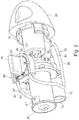
- Fig. 1 shows an embodiment of a device 1 according to the present invention, for repeated dispensing of a mist of an ophthalmic liquid fluid into a person's eye/onto a person's cornea (not shown); the device of the invention is particularly but not exclusively useful for dispensing a mist of such a fluid having a relatively high viscosity and is preferably sized to allow an average person to hold it in his/her hand.
- the shown device 1 comprises an eyelid opener portion 10 and a casing portion 20.
- the eyelid opener portion 10 is configured for keeping a person's eyelid open by being held against the eye region during the dispensing and includes a collar 12 and a connecting structure 14 connecting the collar 12 with a front end F of the casing 20.
- a discharge opening or nozzle 25, which may by way of example be circular or oval, for dispensing the aforementioned mist in the direction towards the collar 12 and, hence, the eye (not shown), is located at the front end F.
- the device 1 generally includes various mechanisms or drives located inside the casing 20 and operable by a person through various operating parts which may include, as shown, one or more of following: a rotatable handle 26, a depressible tab 30, and a rotatable head 28 defining the rear end R of the casing 20.
- Two or more of the shown operating parts 26, 28, 30 may in other embodiments be combined into a single operating part such that more than one of the aforementioned mechanisms or drives are operable by the user manipulating only one operating part.
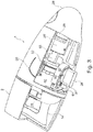
- Fig. 2 shows an internal component structure generally designated numeral 50 and mounted inside the casing 20.
- the component structure 50 supports at one end an outlet structure including the discharge opening 25 and at the other end the rotatable device head 28.
- the rotatable head 28 has a tubular extension 28' and is configured to snap into engagement with the casing 20 via flexible tabs 29, for assisting in the assembly of the device 1.
- the component structure 50 comprises inter alia a container or barrel 70 containing the ophthalmic liquid fluid to be dispensed as a mist, and a first drive for user controlled advancing of a piston 55 with a piston rod and a head (the head not being visible in fig. 2 ) received by a piston cylinder 60.
- the cylinder 60 is configured for storing a first volume of air in an internal air chamber when the piston 55 is in a first, normally fully retracted position.
- the barrel 70 preferably has a movable bottom 72 and/or may be collapsible, has an internal volume allowing for dispensing of multiple doses of the ophthalmic fluid, and may be replaceable to allow for replacement with another and, hence, continued use of the device 1 after one barrel 70 has been emptied.
- the rod of the piston 55 is preferably held against rotation about its longitudinal axis and is generally movable to its first, retracted position from a second, advanced position shown in fig. 2 by rotation of the rotatable device head 28 about an axis parallel with the longitudinal axis of the rod of the piston 55.
- a proximal end part of the rod of the piston 55 remote from the head is shown in fig. 2 and is configured to be receivable within the tubular extension 28' of the rotatable device head 28.
- the rod of the piston 55 has surface track 56 including a spirally winding portion as well as a straight portion 56'.
- the winding portion of the surface track 56 slidably receives a tab located on the inside of the tubular extension 28' whereby rotation of the rotatable head 28 relative to the piston rod brings about a corresponding displacement of the piston 55 from the second position to the retracted first position in which a length of the proximal end part of the rod of the piston 55 shown in fig. 2 is received within the tubular extension 28' of the rotatable head 28.
- the component structure 50 also may include a second drive, preferably in the form of a peristaltic dosing pump 82 or similar, for dispensing a required dose of the liquid fluid into a liquid chamber and/or a mixing chamber to be discussed further below and located at the fore end of the cylinder 60, inside thereof and closest to the discharge opening 25.
- a second drive preferably in the form of a peristaltic dosing pump 82 or similar, for dispensing a required dose of the liquid fluid into a liquid chamber and/or a mixing chamber to be discussed further below and located at the fore end of the cylinder 60, inside thereof and closest to the discharge opening 25.
- Shown in fig. 2 is also a tube 80, preferably a tube flexible along its entire length, which has a first portion 81 and a second portion 81' and which is used for drawing the liquid fluid from the barrel 70.
- the tube 80 connects the barrel 70 with the aforementioned mixing chamber at a connection point 81", via the second drive, eg
- the peristaltic pump 82 includes a housing with a peripheral wall portion 87, shown as a semi-circular wall portion 87, as well as a rotatable disc 84 carrying on the one hand a handle 26 for manually operating the pump 82 and on the other hand two radially oppositely lodged shoes or rollers, of which one roller 86 is seen best in fig. 2 while the opposite roller 86' is seen in fig. 3 .
- a flexible portion of the tube 80 is received between the wall portion 87 and the rotatable disc 84 and is locally squeezed flat between the wall portion 87 and each of the two rollers 86.
- the length of the tube 80 between the locally flattened parts thereof defines a volume or dose of the fluid inside that length which is driven forward into the second portion 81' of the tube 80 by the user rotating the disc 84 and, hence, moving the rollers 86, 86' along the wall portion 87 and the tube portion between disc 84 and the wall portion 87.
- a mechanism (not shown) may be included for limiting rotation of the rotatable disc 84 by eg. 180° per operation, such that manipulation of the handle 26 only allows the user to draw a single dose of predetermined volume of the liquid fluid from the barrel 70 until the time that mechanism is released.
- dosing pumps or positive displacement pumps, may be applied and/or incorporated without departing from the present invention.
- the second drive may be provided with, integrally or not, not shown valve means configured for hindering flow of liquid fluid when the second drive is passive.
- said not shown valve means may be actuated by the piston resting in an extended, i.e. not retracted, position.
- the device 1 may be configured such that the first and the second drives may be activated and/or retracted by means of one button or handle only; eg. the device head 28 and the handle 26. Furthermore, the device 1 may be configured such that first and/or the second drives may be activated and/or retracted and/or released by means of applying a linear force to a pushbutton.
- the container 70 may, in one embodiment, constitute a collapsible bag or pouch made eg. from thin and/or flexible foil; possibly closed by welding. Alternatively, the container 70 may constitute a moulded plastic component.
- the container 70 may, in one embodiment, constitute a cylinder including a movable piston.
- the movable piston may define the bottom of the cylinder and the distal fixed end may be provided with means for hydraulic and/or mechanical interface to the device 1.
- Means, such as a spring, may be provided in order to urge or push the piston into the cylinder. By this, liquid dosing may be facilitated.
- the container 70 may, in one embodiment, be joined to a preferably moulded plastic component allowing for hydraulic and/or mechanical interface to the device 1.
- the liquid container 70 may be integrated with the wet part of the device 1, preferably in a manner allowing for exchangeability of the container 70.
- the separate container 70 may have a unique shape for mechanical orientation and/or fixation of the container with respect to the device 1.
- Fig. 3 shows the device 1 with a protective cap 2 mounted onto the front end F.
- the device 1 of the shown embodiment has a relatively flat casing 20, such as one with a length and width in the order of about 90mm and 60 mm, respectively, allowing it to be conveniently held by the user.
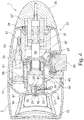
- Fig. 4 shows the device 1 in the first, retracted position of the piston 55, i.e. where the head 54 of the piston is positioned distant from the discharge opening 25 and where a relatively large length of the proximal end part of the rod 57 of the piston 55 is received within the tubular extension 28' of the rotatable head 28.
- the user may displace the piston 55 relative to the cylinder 60 to this first position by rotating the head 28; this displacement is against the force of a spring 61 configured to bias the piston 55 towards the aforementioned second, advanced position by being compressed between the piston head 54 and a rear closure 62 of the cylinder 60.
- the aforementioned tab located inside the tubular extension 28' and engaging the spirally winding portion of surface track 56 is shown in fig.
- the lock mechanism comprises a locking rib 31 connected to the depressible tab 30 (see fig. 1 ) and engaging a recess 32 formed in the outer face of the cylinder 60.
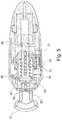
- the rib 31 and the recess 32 are best seen in fig. 5 .
- the depressible tab 30 acts as a lever mechanism by including a depressible arm 32' also shown in fig. 2 , whereby depression of the tab 30 draws the locking rib 31 located at the other end of arm 32' out of engagement with the recess 32 such that the piston 55 is released to move forward to its advanced second position, driven by the spring 61.
- an air chamber 58 in the cylinder 60 has a volume of air of, by way of example, about 820 mm 3 , between the head 54 of the piston 55 and a dispensing structure generally indicated by numeral 90.
- air is simultaneously drawn into this air chamber 58 through an air access port.
- the discharge opening 25 for discharging the mist may be used for this purpose; however, to reduce the risk of contamination of the air chamber 58 by already dispensed liquid fluid being drawn back in together with fresh air the air access port is preferably located elsewhere, such as in the peripheral wall of the cylinder 60 and is preferably equipped with a one-way valve (not shown). Another not shown one-way valve may be located in connection with the discharge opening 25 to prevent or restrict air entry, to prevent the aforementioned contamination. In this manner there is a reduced need for using liquid fluids with preservatives.
- the dispensing structure 90 is preferably inserted into the cylinder 60 to define the foremost end thereof, opposite the rear closure 62. As shown, a passage 91 for a first air flow leads from the air chamber 58 into an internal liquid chamber 92 within the structure 90.
- One or more secondary passages 97 such as three, preferably winding (eg. spirally) around the dispensing structure 90 as in the shown embodiment, are formed and arranged to communicate with the air chamber 58 on the one hand and with a mixing chamber 95 on the other hand.
- the mixing chamber 95 is located in front of the dispensing structure 90 and defined between the dispensing structure 90 and a front casing part 23 that has an aperture defining the discharge opening 25.
- the one or more secondary passages 97 which may have circular cross-section(s), allow for a second air flow to flow past the structure 90 and, hence, the liquid chamber 92, i.e. not through the liquid chamber 92, to enter the mixing chamber 95.
- the dispensing structure 90 may be provided with a laterally oriented port or passage to allow for a liquid flow to the internal liquid fluid chamber 92 from the second portion 81' of the tube 80 via connection point 81", and also has a discharge opening 93 opposite the passage 91.
- the mixing chamber 95 may, as shown in figs. 4 and 5 , follow the general contour of a saucer, with opening 25 being opposite and aligned with the more narrow opening 93 and with the secondary passages 97 opening into the mixing chamber 95 at the "rim" of the saucer.
- Valves opening at a certain pressure may be provided at the normally narrow discharge opening 93 and in passage 91 to retain liquid fluid in the liquid fluid chamber 92, but may be dispensed with, in particular where the liquid fluid has a relatively high viscosity.
- the volume of the liquid fluid chamber 92 corresponds to the aforementioned volume of the dose of liquid fluid dispensed or dosed by the peristaltic pump 82 upon correct manipulation thereof, i.e. proper rotation of the disc 84 through a given angle, by means of handle 26, and may by way of example be in the order of about 50 mm 3 .
- the passage 91, opening 93 and fluid chamber 92 may have a circular cross-section.
- a person When preparing the device 1 for use after a previous discharge/dispensing or when taking the device 1 into use for the first time, a person will fill the fluid chamber 92 using the second drive, in the shown embodiment the peristaltic pump 82, and also withdraw the piston 55 to the retracted, first position. This may, in principle, occur in any sequence, or simultaneously if a single operating part is used for the peristaltic pump 82 and the piston 55.
- the fluid in fluid chamber 92 is represented by dots.
- the speed of the second flow of air leaving the air chamber 58 is preferably high and that the first flow of air discharged by the action of the spring 61 ejects or pushes the liquid fluid out from the liquid fluid chamber 92 through the discharge opening 93 at the forward end of the liquid fluid chamber 92, into the mixing chamber 95.
- Flow of the liquid fluid into the mixing chamber 95 may be assisted by any venturi effect arising from the inflow into the mixing chamber 95 of the secondary air flow.
- a fine mist of the liquid fluid is generated, even where the fluid has a medium to high viscosity, by the second air flow leaving the secondary passages 97 impinging on the simultaneously ejected liquid fluid, in front of the discharge opening 93.
- the forward second air flow preferably strikes the ejected liquid fluid at an acute angle with respect to the general forward direction of flow of the ejected liquid fluid.
- the fine mist generated thereby exits the device 1 through the discharge opening 25 with high inertia, as determined i.a. by the spring 61, towards the eye of the user, which eye is held open by the eyelid opener portion 10.
- the relative dimensions of the one or more passages 97 in relation to the dimension of passage 91 leading into the liquid fluid chamber 92 and the discharge opening 93 leading out there from any desired flow and droplet size may be obtained. It may in some instances be preferred that the liquid fluid is ejected into a second flow of air already prevailing in the mixing chamber 95.
- the volume of the liquid fluid standing in the second tube portion 81' will remain therein during discharge of the liquid fluid in the liquid fluid chamber 92.
- the seal provided by the roller 86' of the peristaltic pump 82 prevents this volume from being drawn into the liquid fluid chamber 92 as the liquid fluid therein is ejected by the air.
- All components of the device mentioned above may be of any desired material, such as a plastics material, a metal material or combinations thereof.
- the collar for keeping the user's eyelid open may carry a surface material with antibacterial properties or be formed from such a material.
- the components and/or surfaces defining and/or surrounding the discharge opening 25 and/or nozzle may be made from a material with antibacterial properties.
- first and second flows of air are established, which may be preferred where the liquid fluid has a high viscosity, in other cases it may not be required to provide for a secondary flow of air, by configuring the discharge opening 25 as a nozzle suitable for establishing by its geometry alone a small droplet size of the liquid fluid dispensed by the first drive.
Landscapes
- Health & Medical Sciences (AREA)
- Engineering & Computer Science (AREA)
- General Health & Medical Sciences (AREA)
- Public Health (AREA)
- Heart & Thoracic Surgery (AREA)
- Veterinary Medicine (AREA)
- Life Sciences & Earth Sciences (AREA)
- Animal Behavior & Ethology (AREA)
- Biomedical Technology (AREA)
- Mechanical Engineering (AREA)
- Ophthalmology & Optometry (AREA)
- Vascular Medicine (AREA)
- Anesthesiology (AREA)
- Hematology (AREA)
- Containers And Packaging Bodies Having A Special Means To Remove Contents (AREA)
- Medical Preparation Storing Or Oral Administration Devices (AREA)
Priority Applications (3)
| Application Number | Priority Date | Filing Date | Title |
|---|---|---|---|
| EP18193501.6A EP3427782B1 (en) | 2014-01-31 | 2015-02-02 | A device for applying an ophthalmic fluid |
| PL15709623T PL3099362T3 (pl) | 2014-01-31 | 2015-02-02 | Urządzenie do aplikowania płynu do oczu |
| PL18193501T PL3427782T3 (pl) | 2014-01-31 | 2015-02-02 | Urządzenie do aplikowania płynu oftalmicznego |
Applications Claiming Priority (3)
| Application Number | Priority Date | Filing Date | Title |
|---|---|---|---|
| DKPA201470045 | 2014-01-31 | ||
| DKPA201470046 | 2014-01-31 | ||
| PCT/EP2015/052072 WO2015114139A1 (en) | 2014-01-31 | 2015-02-02 | A device for applying an ophthalmic fluid |
Related Child Applications (1)
| Application Number | Title | Priority Date | Filing Date |
|---|---|---|---|
| EP18193501.6A Division EP3427782B1 (en) | 2014-01-31 | 2015-02-02 | A device for applying an ophthalmic fluid |
Publications (2)
| Publication Number | Publication Date |
|---|---|
| EP3099362A1 EP3099362A1 (en) | 2016-12-07 |
| EP3099362B1 true EP3099362B1 (en) | 2018-09-12 |
Family
ID=52672229
Family Applications (2)
| Application Number | Title | Priority Date | Filing Date |
|---|---|---|---|
| EP18193501.6A Active EP3427782B1 (en) | 2014-01-31 | 2015-02-02 | A device for applying an ophthalmic fluid |
| EP15709623.1A Active EP3099362B1 (en) | 2014-01-31 | 2015-02-02 | A device for applying an ophthalmic fluid |
Family Applications Before (1)
| Application Number | Title | Priority Date | Filing Date |
|---|---|---|---|
| EP18193501.6A Active EP3427782B1 (en) | 2014-01-31 | 2015-02-02 | A device for applying an ophthalmic fluid |
Country Status (7)
| Country | Link |
|---|---|
| US (1) | US10265216B2 (pt) |
| EP (2) | EP3427782B1 (pt) |
| JP (2) | JP6599364B2 (pt) |
| ES (2) | ES2700365T3 (pt) |
| PL (2) | PL3099362T3 (pt) |
| PT (2) | PT3099362T (pt) |
| WO (1) | WO2015114139A1 (pt) |
Families Citing this family (11)
| Publication number | Priority date | Publication date | Assignee | Title |
|---|---|---|---|---|
| AU2016303240A1 (en) * | 2015-08-04 | 2018-02-22 | Eye-go A/S | A device for applying an ophthalmic fluid |
| CA3066408A1 (en) | 2017-06-10 | 2018-12-13 | Eyenovia, Inc. | Methods and devices for handling a fluid and delivering the fluid to the eye |
| US11738158B2 (en) | 2017-10-04 | 2023-08-29 | Pneuma Respiratory, Inc. | Electronic breath actuated in-line droplet delivery device and methods of use |
| CA3082192A1 (en) | 2017-11-08 | 2019-05-16 | Pneuma Respiratory, Inc. | Electronic breath actuated in-line droplet delivery device with small volume ampoule and methods of use |
| CN109602537B (zh) * | 2018-12-27 | 2020-12-15 | 永目堂有限公司 | 一种眼科辅助滴眼设备 |
| JP2023551060A (ja) | 2020-11-30 | 2023-12-06 | アイ-ゴー・アー/エス | 用量分の眼科用液体の噴霧剤を送達するためのデバイス、および眼科用液体の噴霧剤を送達するためのデバイスに適したポンプ |
| FR3118880B1 (fr) * | 2021-01-20 | 2024-04-05 | Oreal | Systeme d’atomisation et d’ejection de liquide pour une administration transdermique |
| KR20240037245A (ko) | 2021-06-22 | 2024-03-21 | 뉴마 레스퍼러토리 인코포레이티드 | 푸시 이젝션에 의한 액적 전달 장치 |
| WO2023017724A1 (en) * | 2021-08-11 | 2023-02-16 | L'oreal | Venturi device having a multi-injection port for liquid formula atomization |
| FR3127142A1 (fr) * | 2021-09-17 | 2023-03-24 | L'oreal | dispositif venturi avec un orifice d’injection multiple pour UNE atomisation de formule liquide |
| WO2023091637A1 (en) * | 2021-11-18 | 2023-05-25 | Pneuma Respiratory, Inc. | Droplet delivery device for treating eye conditions |
Family Cites Families (46)
| Publication number | Priority date | Publication date | Assignee | Title |
|---|---|---|---|---|
| US2524720A (en) * | 1946-07-24 | 1950-10-03 | Charles A Watrous | Eye-bathing device |
| CH528272A (de) | 1970-08-13 | 1972-09-30 | Maurice David Myer | Gerät zur Einbringung eines flüssigen Medikamentes in ein Auge |
| US3934585A (en) | 1970-08-13 | 1976-01-27 | Maurice David M | Method and apparatus for application of eye drops |
| GB2272389B (en) * | 1992-11-04 | 1996-07-24 | Bespak Plc | Dispensing apparatus |
| GB2291135B (en) * | 1994-07-06 | 1998-02-25 | Boehringer Ingelheim Kg | Device for dispensing fluid |
| NL1001366C2 (nl) | 1995-10-06 | 1997-04-08 | Airspray Int Bv | Inrichting voor het afgeven van een luchtvloeistofmengsel, in het bijzonder schuim en daarvoor bestemde bedieningseenheid. |
| DE19545226C1 (de) * | 1995-12-05 | 1997-06-19 | Boehringer Ingelheim Int | Sperrspannwerk für einen federbetätigten Abtrieb |
| US6033384A (en) | 1997-12-18 | 2000-03-07 | Py; Daniel | One-way actuation release mechanism for a system for applying medicament |
| US5997518A (en) * | 1998-01-14 | 1999-12-07 | Laibovitz; Robert A. | Apparatus and method for delivery of small volumes of liquid |
| US6159188A (en) | 1998-01-14 | 2000-12-12 | Robert L. Rogers | Apparatus and method for delivery of micro and submicro quantities of materials |
| AUPQ930900A0 (en) | 2000-08-10 | 2000-08-31 | Wright, James Grant | Dispensing device |
| SE0100418D0 (sv) | 2001-02-08 | 2001-02-08 | Pharmacia Ab | Liquid delivery device and use method |
| US6758837B2 (en) | 2001-02-08 | 2004-07-06 | Pharmacia Ab | Liquid delivery device and method of use thereof |
| US6811805B2 (en) | 2001-05-30 | 2004-11-02 | Novatis Ag | Method for applying a coating |
| DE10131178A1 (de) | 2001-06-29 | 2003-01-16 | Boehringer Ingelheim Pharma | Vernebler zur Applikation von Flüssigkeiten in die Augen |
| CA2526362C (en) | 2003-05-20 | 2012-10-09 | James F. Collins | Ophthalmic drug delivery system |
| US20100222752A1 (en) * | 2003-05-20 | 2010-09-02 | Collins Jr James F | Ophthalmic fluid delivery system |
| US8545463B2 (en) | 2003-05-20 | 2013-10-01 | Optimyst Systems Inc. | Ophthalmic fluid reservoir assembly for use with an ophthalmic fluid delivery device |
| JP2005021254A (ja) * | 2003-06-30 | 2005-01-27 | Yoshino Kogyosho Co Ltd | 洗眼容器 |
| US20050027241A1 (en) | 2003-07-30 | 2005-02-03 | Yeakley Rourke M. | Wound and eye irrigator |
| US7077831B2 (en) * | 2003-12-11 | 2006-07-18 | Stephanie Skolik | Ophthalmic fluid dispenser |
| US20050240162A1 (en) | 2004-04-21 | 2005-10-27 | Wen-Pin Chen | Eye treatment device |
| US7226435B2 (en) | 2004-10-14 | 2007-06-05 | Alcon, Inc. | Drug delivery device |
| JP2008528072A (ja) | 2005-01-20 | 2008-07-31 | アイ−シャイン・ダンマーク・アンパルトセルスカブ | 液供給装置 |
| US7621897B1 (en) | 2005-12-05 | 2009-11-24 | Berke Joseph J | Ophthalmic fluid applicator and method |
| EP2016778A4 (en) | 2006-05-11 | 2010-07-28 | Eran Eilat | EYE MEDICINES DONOR |
| WO2008041177A2 (en) | 2006-10-02 | 2008-04-10 | I-Shine Danmark Aps | A dispensing device and a method of using the device |
| US8579856B2 (en) * | 2007-05-16 | 2013-11-12 | Mystic Pharmaceuticals, Inc. | Unit dose drug delivery platform |
| US7981097B2 (en) * | 2008-03-27 | 2011-07-19 | Paoli Jr Alexander Delli | Medical device for the treatment and prevention of eye and respiratory tract conditions |
| ITMI20081515A1 (it) | 2008-08-11 | 2010-02-12 | Duotech S R L | "flacone per farmaci liquidi a doppia camera" |
| DE202009007205U1 (de) | 2009-05-19 | 2009-10-15 | Plum A/S | Augenspülvorrichtung |
| EP2456509A1 (en) | 2009-07-22 | 2012-05-30 | Advanced Ophthalmic Pharma Ltd. | Device for applying an ophthalmic medicament mist |
| EA201390120A3 (ru) | 2010-07-15 | 2013-09-30 | Коринтиан Офтэлмик, Инк. | Доставка офтальмологических лекарственных средств |
| EA201390122A1 (ru) | 2010-07-15 | 2014-05-30 | Коринтиан Офтэлмик, Инк. | Устройство для генерирования капель |
| JP2013531548A (ja) | 2010-07-15 | 2013-08-08 | コリンシアン オフサルミック,インコーポレイティド | 遠隔治療及び遠隔モニタリングを実施する方法及びシステム |
| JP2014504178A (ja) | 2010-11-29 | 2014-02-20 | サノフィ−アベンティス・ドイチュラント・ゲゼルシャフト・ミット・ベシュレンクテル・ハフツング | 薬用モジュールを備えた眼科用薬物送達デバイス |
| GB2488992A (en) * | 2011-03-10 | 2012-09-19 | Advanced Ophthalmic Pharma Ltd | Medicament dispenser |
| TW201242627A (en) * | 2011-04-29 | 2012-11-01 | Middleland Sensing Technology Inc | Nebulizer for treating eyes |
| JP6092194B2 (ja) | 2011-05-18 | 2017-03-08 | ケリー, ナイジャルKELLY, Nigel | 液体ディスペンサー |
| CN104487028A (zh) | 2011-12-12 | 2015-04-01 | 艾诺维亚股份有限公司 | 高模量聚合物喷射器机构、喷射器装置及其使用方法 |
| WO2013155201A2 (en) | 2012-04-10 | 2013-10-17 | Corinthian Ophthalmic, Inc. | Spray ejector mechanisms and devices providing charge isolation and controllable droplet charge, and low dosage volume opthalmic administration |
| MX2014012702A (es) | 2012-04-20 | 2015-08-14 | Eyenovia Inc | Dispositivo eyector de aspersion y metodos de uso. |
| US20130299518A1 (en) * | 2012-05-09 | 2013-11-14 | Gojo Industries, Inc. | Foam dispensers and refill units for foam dispensers |
| US9611839B2 (en) * | 2012-05-09 | 2017-04-04 | Gojo Industries, Inc. | Low residual inverted pumps, dispensers and refill units |
| US9463486B2 (en) | 2012-05-14 | 2016-10-11 | Eyenovia, Inc. | Laminar flow droplet generator device and methods of use |
| KR102234042B1 (ko) | 2012-05-15 | 2021-03-30 | 아이노비아 인코포레이티드 | 이젝터 디바이스들, 방법들, 드라이버들, 및 그를 위한 회로들 |
-
2015
- 2015-02-02 EP EP18193501.6A patent/EP3427782B1/en active Active
- 2015-02-02 US US15/115,462 patent/US10265216B2/en active Active
- 2015-02-02 WO PCT/EP2015/052072 patent/WO2015114139A1/en active Application Filing
- 2015-02-02 ES ES15709623T patent/ES2700365T3/es active Active
- 2015-02-02 PT PT15709623T patent/PT3099362T/pt unknown
- 2015-02-02 ES ES18193501T patent/ES2781805T3/es active Active
- 2015-02-02 EP EP15709623.1A patent/EP3099362B1/en active Active
- 2015-02-02 PL PL15709623T patent/PL3099362T3/pl unknown
- 2015-02-02 PT PT181935016T patent/PT3427782T/pt unknown
- 2015-02-02 PL PL18193501T patent/PL3427782T3/pl unknown
- 2015-02-02 JP JP2016567158A patent/JP6599364B2/ja active Active
-
2019
- 2019-10-01 JP JP2019181427A patent/JP6827508B2/ja active Active
Non-Patent Citations (1)
| Title |
|---|
| None * |
Also Published As
| Publication number | Publication date |
|---|---|
| JP2017504460A (ja) | 2017-02-09 |
| JP2019217365A (ja) | 2019-12-26 |
| PL3099362T3 (pl) | 2019-02-28 |
| JP6827508B2 (ja) | 2021-02-10 |
| PT3099362T (pt) | 2018-12-04 |
| PT3427782T (pt) | 2020-04-08 |
| ES2781805T3 (es) | 2020-09-07 |
| US20170007449A1 (en) | 2017-01-12 |
| EP3427782B1 (en) | 2020-01-29 |
| EP3099362A1 (en) | 2016-12-07 |
| PL3427782T3 (pl) | 2020-06-29 |
| EP3427782A1 (en) | 2019-01-16 |
| ES2700365T3 (es) | 2019-02-15 |
| US10265216B2 (en) | 2019-04-23 |
| JP6599364B2 (ja) | 2019-10-30 |
| WO2015114139A1 (en) | 2015-08-06 |
Similar Documents
| Publication | Publication Date | Title |
|---|---|---|
| EP3099362B1 (en) | A device for applying an ophthalmic fluid | |
| EP3331479B1 (en) | A device for applying an ophthalmic fluid | |
| US8210167B2 (en) | Manually operated monodose nasal sprayer | |
| US7857169B2 (en) | Rectangular metered dispenser with feed-containing piston drive mechanism | |
| ES2312516T3 (es) | Atomizador accionado manualmente. | |
| EP2349657B1 (en) | Fluid dispensing hair removal device | |
| JP2014532445A5 (ja) | アプリケータ及びアプリケータシステム | |
| EA007403B1 (ru) | Устройство для выдачи жидкостей, используемый в нём сменный баллончик и система, состоящая из устройства для выдачи жидкостей и сменного баллончика | |
| JPH05509241A (ja) | 計量投薬量吸引器 | |
| US20080210228A1 (en) | Monodose nasal sprayer | |
| JP2018522669A5 (pt) | ||
| US20150239138A1 (en) | Self-contained Shaving System | |
| JP2023551060A (ja) | 用量分の眼科用液体の噴霧剤を送達するためのデバイス、および眼科用液体の噴霧剤を送達するためのデバイスに適したポンプ | |
| RU2807165C2 (ru) | Ингаляционное устройство и способ его использования | |
| BR112019022196B1 (pt) | Dispositivo de inalação | |
| CZ20002255A3 (cs) | Zařízení pro dodávání kapaliny obsahující lék |
Legal Events
| Date | Code | Title | Description |
|---|---|---|---|
| PUAI | Public reference made under article 153(3) epc to a published international application that has entered the european phase |
Free format text: ORIGINAL CODE: 0009012 |
|
| STAA | Information on the status of an ep patent application or granted ep patent |
Free format text: STATUS: REQUEST FOR EXAMINATION WAS MADE |
|
| 17P | Request for examination filed |
Effective date: 20160818 |
|
| AK | Designated contracting states |
Kind code of ref document: A1 Designated state(s): AL AT BE BG CH CY CZ DE DK EE ES FI FR GB GR HR HU IE IS IT LI LT LU LV MC MK MT NL NO PL PT RO RS SE SI SK SM TR |
|
| AX | Request for extension of the european patent |
Extension state: BA ME |
|
| DAX | Request for extension of the european patent (deleted) | ||
| GRAP | Despatch of communication of intention to grant a patent |
Free format text: ORIGINAL CODE: EPIDOSNIGR1 |
|
| STAA | Information on the status of an ep patent application or granted ep patent |
Free format text: STATUS: GRANT OF PATENT IS INTENDED |
|
| INTG | Intention to grant announced |
Effective date: 20171106 |
|
| GRAS | Grant fee paid |
Free format text: ORIGINAL CODE: EPIDOSNIGR3 |
|
| GRAA | (expected) grant |
Free format text: ORIGINAL CODE: 0009210 |
|
| STAA | Information on the status of an ep patent application or granted ep patent |
Free format text: STATUS: THE PATENT HAS BEEN GRANTED |
|
| AK | Designated contracting states |
Kind code of ref document: B1 Designated state(s): AL AT BE BG CH CY CZ DE DK EE ES FI FR GB GR HR HU IE IS IT LI LT LU LV MC MK MT NL NO PL PT RO RS SE SI SK SM TR |
|
| REG | Reference to a national code |
Ref country code: GB Ref legal event code: FG4D |
|
| REG | Reference to a national code |
Ref country code: CH Ref legal event code: EP |
|
| REG | Reference to a national code |
Ref country code: IE Ref legal event code: FG4D |
|
| REG | Reference to a national code |
Ref country code: DE Ref legal event code: R096 Ref document number: 602015016060 Country of ref document: DE |
|
| REG | Reference to a national code |
Ref country code: AT Ref legal event code: REF Ref document number: 1039824 Country of ref document: AT Kind code of ref document: T Effective date: 20181015 |
|
| REG | Reference to a national code |
Ref country code: CH Ref legal event code: NV Representative=s name: ISLER AND PEDRAZZINI AG, CH |
|
| REG | Reference to a national code |
Ref country code: PT Ref legal event code: SC4A Ref document number: 3099362 Country of ref document: PT Date of ref document: 20181204 Kind code of ref document: T Free format text: AVAILABILITY OF NATIONAL TRANSLATION Effective date: 20181128 |
|
| REG | Reference to a national code |
Ref country code: NL Ref legal event code: FP |
|
| REG | Reference to a national code |
Ref country code: SE Ref legal event code: TRGR |
|
| REG | Reference to a national code |
Ref country code: LT Ref legal event code: MG4D |
|
| PG25 | Lapsed in a contracting state [announced via postgrant information from national office to epo] |
Ref country code: LT Free format text: LAPSE BECAUSE OF FAILURE TO SUBMIT A TRANSLATION OF THE DESCRIPTION OR TO PAY THE FEE WITHIN THE PRESCRIBED TIME-LIMIT Effective date: 20180912 Ref country code: RS Free format text: LAPSE BECAUSE OF FAILURE TO SUBMIT A TRANSLATION OF THE DESCRIPTION OR TO PAY THE FEE WITHIN THE PRESCRIBED TIME-LIMIT Effective date: 20180912 Ref country code: GR Free format text: LAPSE BECAUSE OF FAILURE TO SUBMIT A TRANSLATION OF THE DESCRIPTION OR TO PAY THE FEE WITHIN THE PRESCRIBED TIME-LIMIT Effective date: 20181213 Ref country code: BG Free format text: LAPSE BECAUSE OF FAILURE TO SUBMIT A TRANSLATION OF THE DESCRIPTION OR TO PAY THE FEE WITHIN THE PRESCRIBED TIME-LIMIT Effective date: 20181212 |
|
| REG | Reference to a national code |
Ref country code: NO Ref legal event code: T2 Effective date: 20180912 |
|
| REG | Reference to a national code |
Ref country code: ES Ref legal event code: FG2A Ref document number: 2700365 Country of ref document: ES Kind code of ref document: T3 Effective date: 20190215 |
|
| PG25 | Lapsed in a contracting state [announced via postgrant information from national office to epo] |
Ref country code: LV Free format text: LAPSE BECAUSE OF FAILURE TO SUBMIT A TRANSLATION OF THE DESCRIPTION OR TO PAY THE FEE WITHIN THE PRESCRIBED TIME-LIMIT Effective date: 20180912 Ref country code: HR Free format text: LAPSE BECAUSE OF FAILURE TO SUBMIT A TRANSLATION OF THE DESCRIPTION OR TO PAY THE FEE WITHIN THE PRESCRIBED TIME-LIMIT Effective date: 20180912 Ref country code: AL Free format text: LAPSE BECAUSE OF FAILURE TO SUBMIT A TRANSLATION OF THE DESCRIPTION OR TO PAY THE FEE WITHIN THE PRESCRIBED TIME-LIMIT Effective date: 20180912 |
|
| PG25 | Lapsed in a contracting state [announced via postgrant information from national office to epo] |
Ref country code: IT Free format text: LAPSE BECAUSE OF FAILURE TO SUBMIT A TRANSLATION OF THE DESCRIPTION OR TO PAY THE FEE WITHIN THE PRESCRIBED TIME-LIMIT Effective date: 20180912 Ref country code: RO Free format text: LAPSE BECAUSE OF FAILURE TO SUBMIT A TRANSLATION OF THE DESCRIPTION OR TO PAY THE FEE WITHIN THE PRESCRIBED TIME-LIMIT Effective date: 20180912 Ref country code: CZ Free format text: LAPSE BECAUSE OF FAILURE TO SUBMIT A TRANSLATION OF THE DESCRIPTION OR TO PAY THE FEE WITHIN THE PRESCRIBED TIME-LIMIT Effective date: 20180912 Ref country code: IS Free format text: LAPSE BECAUSE OF FAILURE TO SUBMIT A TRANSLATION OF THE DESCRIPTION OR TO PAY THE FEE WITHIN THE PRESCRIBED TIME-LIMIT Effective date: 20190112 Ref country code: EE Free format text: LAPSE BECAUSE OF FAILURE TO SUBMIT A TRANSLATION OF THE DESCRIPTION OR TO PAY THE FEE WITHIN THE PRESCRIBED TIME-LIMIT Effective date: 20180912 |
|
| PG25 | Lapsed in a contracting state [announced via postgrant information from national office to epo] |
Ref country code: SK Free format text: LAPSE BECAUSE OF FAILURE TO SUBMIT A TRANSLATION OF THE DESCRIPTION OR TO PAY THE FEE WITHIN THE PRESCRIBED TIME-LIMIT Effective date: 20180912 Ref country code: SM Free format text: LAPSE BECAUSE OF FAILURE TO SUBMIT A TRANSLATION OF THE DESCRIPTION OR TO PAY THE FEE WITHIN THE PRESCRIBED TIME-LIMIT Effective date: 20180912 |
|
| REG | Reference to a national code |
Ref country code: DE Ref legal event code: R097 Ref document number: 602015016060 Country of ref document: DE |
|
| REG | Reference to a national code |
Ref country code: AT Ref legal event code: UEP Ref document number: 1039824 Country of ref document: AT Kind code of ref document: T Effective date: 20180912 |
|
| PLBE | No opposition filed within time limit |
Free format text: ORIGINAL CODE: 0009261 |
|
| STAA | Information on the status of an ep patent application or granted ep patent |
Free format text: STATUS: NO OPPOSITION FILED WITHIN TIME LIMIT |
|
| PG25 | Lapsed in a contracting state [announced via postgrant information from national office to epo] |
Ref country code: DK Free format text: LAPSE BECAUSE OF FAILURE TO SUBMIT A TRANSLATION OF THE DESCRIPTION OR TO PAY THE FEE WITHIN THE PRESCRIBED TIME-LIMIT Effective date: 20180912 |
|
| 26N | No opposition filed |
Effective date: 20190613 |
|
| PG25 | Lapsed in a contracting state [announced via postgrant information from national office to epo] |
Ref country code: SI Free format text: LAPSE BECAUSE OF FAILURE TO SUBMIT A TRANSLATION OF THE DESCRIPTION OR TO PAY THE FEE WITHIN THE PRESCRIBED TIME-LIMIT Effective date: 20180912 |
|
| PG25 | Lapsed in a contracting state [announced via postgrant information from national office to epo] |
Ref country code: MC Free format text: LAPSE BECAUSE OF FAILURE TO SUBMIT A TRANSLATION OF THE DESCRIPTION OR TO PAY THE FEE WITHIN THE PRESCRIBED TIME-LIMIT Effective date: 20180912 Ref country code: LU Free format text: LAPSE BECAUSE OF NON-PAYMENT OF DUE FEES Effective date: 20190202 |
|
| PG25 | Lapsed in a contracting state [announced via postgrant information from national office to epo] |
Ref country code: TR Free format text: LAPSE BECAUSE OF FAILURE TO SUBMIT A TRANSLATION OF THE DESCRIPTION OR TO PAY THE FEE WITHIN THE PRESCRIBED TIME-LIMIT Effective date: 20180912 |
|
| PG25 | Lapsed in a contracting state [announced via postgrant information from national office to epo] |
Ref country code: MT Free format text: LAPSE BECAUSE OF NON-PAYMENT OF DUE FEES Effective date: 20190202 |
|
| PG25 | Lapsed in a contracting state [announced via postgrant information from national office to epo] |
Ref country code: CY Free format text: LAPSE BECAUSE OF FAILURE TO SUBMIT A TRANSLATION OF THE DESCRIPTION OR TO PAY THE FEE WITHIN THE PRESCRIBED TIME-LIMIT Effective date: 20180912 |
|
| PG25 | Lapsed in a contracting state [announced via postgrant information from national office to epo] |
Ref country code: HU Free format text: LAPSE BECAUSE OF FAILURE TO SUBMIT A TRANSLATION OF THE DESCRIPTION OR TO PAY THE FEE WITHIN THE PRESCRIBED TIME-LIMIT; INVALID AB INITIO Effective date: 20150202 |
|
| PG25 | Lapsed in a contracting state [announced via postgrant information from national office to epo] |
Ref country code: MK Free format text: LAPSE BECAUSE OF FAILURE TO SUBMIT A TRANSLATION OF THE DESCRIPTION OR TO PAY THE FEE WITHIN THE PRESCRIBED TIME-LIMIT Effective date: 20180912 |
|
| PGFP | Annual fee paid to national office [announced via postgrant information from national office to epo] |
Ref country code: NO Payment date: 20230111 Year of fee payment: 9 Ref country code: FR Payment date: 20230120 Year of fee payment: 9 |
|
| PGFP | Annual fee paid to national office [announced via postgrant information from national office to epo] |
Ref country code: SE Payment date: 20230208 Year of fee payment: 9 Ref country code: PL Payment date: 20230201 Year of fee payment: 9 Ref country code: BE Payment date: 20230111 Year of fee payment: 9 |
|
| P01 | Opt-out of the competence of the unified patent court (upc) registered |
Effective date: 20230525 |
|
| PGFP | Annual fee paid to national office [announced via postgrant information from national office to epo] |
Ref country code: NL Payment date: 20240116 Year of fee payment: 10 |
|
| PGFP | Annual fee paid to national office [announced via postgrant information from national office to epo] |
Ref country code: IE Payment date: 20240116 Year of fee payment: 10 Ref country code: ES Payment date: 20240318 Year of fee payment: 10 |
|
| PGFP | Annual fee paid to national office [announced via postgrant information from national office to epo] |
Ref country code: AT Payment date: 20240116 Year of fee payment: 10 |
|
| PGFP | Annual fee paid to national office [announced via postgrant information from national office to epo] |
Ref country code: DE Payment date: 20240116 Year of fee payment: 10 Ref country code: FI Payment date: 20240116 Year of fee payment: 10 Ref country code: CH Payment date: 20240301 Year of fee payment: 10 Ref country code: GB Payment date: 20240129 Year of fee payment: 10 Ref country code: PT Payment date: 20240118 Year of fee payment: 10 |