EP3098928A1 - Power control system and method for controlling power control system - Google Patents
Power control system and method for controlling power control system Download PDFInfo
- Publication number
- EP3098928A1 EP3098928A1 EP15740623.2A EP15740623A EP3098928A1 EP 3098928 A1 EP3098928 A1 EP 3098928A1 EP 15740623 A EP15740623 A EP 15740623A EP 3098928 A1 EP3098928 A1 EP 3098928A1
- Authority
- EP
- European Patent Office
- Prior art keywords
- power
- generation device
- current
- dummy
- power generation
- Prior art date
- Legal status (The legal status is an assumption and is not a legal conclusion. Google has not performed a legal analysis and makes no representation as to the accuracy of the status listed.)
- Granted
Links
- 238000000034 method Methods 0.000 title claims description 13
- 238000010248 power generation Methods 0.000 claims abstract description 153
- 239000000446 fuel Substances 0.000 claims description 15
- 230000001360 synchronised effect Effects 0.000 description 39
- 238000010586 diagram Methods 0.000 description 24
- 238000004891 communication Methods 0.000 description 12
- 239000007789 gas Substances 0.000 description 11
- 230000006870 function Effects 0.000 description 9
- 230000002441 reversible effect Effects 0.000 description 6
- 238000001514 detection method Methods 0.000 description 5
- 238000006243 chemical reaction Methods 0.000 description 3
- 230000008901 benefit Effects 0.000 description 2
- 230000005540 biological transmission Effects 0.000 description 2
- 230000008859 change Effects 0.000 description 2
- 238000005516 engineering process Methods 0.000 description 2
- 238000012986 modification Methods 0.000 description 2
- 230000004048 modification Effects 0.000 description 2
- 230000007935 neutral effect Effects 0.000 description 2
- 230000003287 optical effect Effects 0.000 description 2
- UFHFLCQGNIYNRP-UHFFFAOYSA-N Hydrogen Chemical compound [H][H] UFHFLCQGNIYNRP-UHFFFAOYSA-N 0.000 description 1
- HBBGRARXTFLTSG-UHFFFAOYSA-N Lithium ion Chemical compound [Li+] HBBGRARXTFLTSG-UHFFFAOYSA-N 0.000 description 1
- QVGXLLKOCUKJST-UHFFFAOYSA-N atomic oxygen Chemical compound [O] QVGXLLKOCUKJST-UHFFFAOYSA-N 0.000 description 1
- 230000002457 bidirectional effect Effects 0.000 description 1
- 230000010267 cellular communication Effects 0.000 description 1
- 230000001413 cellular effect Effects 0.000 description 1
- 230000003247 decreasing effect Effects 0.000 description 1
- 238000007599 discharging Methods 0.000 description 1
- 230000000694 effects Effects 0.000 description 1
- 239000001257 hydrogen Substances 0.000 description 1
- 229910052739 hydrogen Inorganic materials 0.000 description 1
- 238000009434 installation Methods 0.000 description 1
- 229910001416 lithium ion Inorganic materials 0.000 description 1
- 230000007774 longterm Effects 0.000 description 1
- 239000011159 matrix material Substances 0.000 description 1
- 229910052987 metal hydride Inorganic materials 0.000 description 1
- 229910021421 monocrystalline silicon Inorganic materials 0.000 description 1
- 239000001301 oxygen Substances 0.000 description 1
- 229910052760 oxygen Inorganic materials 0.000 description 1
- 229910021420 polycrystalline silicon Inorganic materials 0.000 description 1
- 230000004044 response Effects 0.000 description 1
- 239000007787 solid Substances 0.000 description 1
- 239000010409 thin film Substances 0.000 description 1
- 238000004804 winding Methods 0.000 description 1
Images


Classifications
-
- H—ELECTRICITY
- H02—GENERATION; CONVERSION OR DISTRIBUTION OF ELECTRIC POWER
- H02J—CIRCUIT ARRANGEMENTS OR SYSTEMS FOR SUPPLYING OR DISTRIBUTING ELECTRIC POWER; SYSTEMS FOR STORING ELECTRIC ENERGY
- H02J3/00—Circuit arrangements for ac mains or ac distribution networks
- H02J3/38—Arrangements for parallely feeding a single network by two or more generators, converters or transformers
- H02J3/381—Dispersed generators
-
- H—ELECTRICITY
- H02—GENERATION; CONVERSION OR DISTRIBUTION OF ELECTRIC POWER
- H02J—CIRCUIT ARRANGEMENTS OR SYSTEMS FOR SUPPLYING OR DISTRIBUTING ELECTRIC POWER; SYSTEMS FOR STORING ELECTRIC ENERGY
- H02J7/00—Circuit arrangements for charging or depolarising batteries or for supplying loads from batteries
- H02J7/0068—Battery or charger load switching, e.g. concurrent charging and load supply
-
- H—ELECTRICITY
- H02—GENERATION; CONVERSION OR DISTRIBUTION OF ELECTRIC POWER
- H02J—CIRCUIT ARRANGEMENTS OR SYSTEMS FOR SUPPLYING OR DISTRIBUTING ELECTRIC POWER; SYSTEMS FOR STORING ELECTRIC ENERGY
- H02J7/00—Circuit arrangements for charging or depolarising batteries or for supplying loads from batteries
- H02J7/34—Parallel operation in networks using both storage and other dc sources, e.g. providing buffering
- H02J7/35—Parallel operation in networks using both storage and other dc sources, e.g. providing buffering with light sensitive cells
-
- H—ELECTRICITY
- H02—GENERATION; CONVERSION OR DISTRIBUTION OF ELECTRIC POWER
- H02J—CIRCUIT ARRANGEMENTS OR SYSTEMS FOR SUPPLYING OR DISTRIBUTING ELECTRIC POWER; SYSTEMS FOR STORING ELECTRIC ENERGY
- H02J9/00—Circuit arrangements for emergency or stand-by power supply, e.g. for emergency lighting
- H02J9/04—Circuit arrangements for emergency or stand-by power supply, e.g. for emergency lighting in which the distribution system is disconnected from the normal source and connected to a standby source
- H02J9/06—Circuit arrangements for emergency or stand-by power supply, e.g. for emergency lighting in which the distribution system is disconnected from the normal source and connected to a standby source with automatic change-over, e.g. UPS systems
- H02J9/062—Circuit arrangements for emergency or stand-by power supply, e.g. for emergency lighting in which the distribution system is disconnected from the normal source and connected to a standby source with automatic change-over, e.g. UPS systems for AC powered loads
-
- H—ELECTRICITY
- H02—GENERATION; CONVERSION OR DISTRIBUTION OF ELECTRIC POWER
- H02M—APPARATUS FOR CONVERSION BETWEEN AC AND AC, BETWEEN AC AND DC, OR BETWEEN DC AND DC, AND FOR USE WITH MAINS OR SIMILAR POWER SUPPLY SYSTEMS; CONVERSION OF DC OR AC INPUT POWER INTO SURGE OUTPUT POWER; CONTROL OR REGULATION THEREOF
- H02M7/00—Conversion of ac power input into dc power output; Conversion of dc power input into ac power output
- H02M7/42—Conversion of dc power input into ac power output without possibility of reversal
- H02M7/44—Conversion of dc power input into ac power output without possibility of reversal by static converters
-
- H—ELECTRICITY
- H02—GENERATION; CONVERSION OR DISTRIBUTION OF ELECTRIC POWER
- H02J—CIRCUIT ARRANGEMENTS OR SYSTEMS FOR SUPPLYING OR DISTRIBUTING ELECTRIC POWER; SYSTEMS FOR STORING ELECTRIC ENERGY
- H02J2300/00—Systems for supplying or distributing electric power characterised by decentralized, dispersed, or local generation
- H02J2300/20—The dispersed energy generation being of renewable origin
- H02J2300/22—The renewable source being solar energy
- H02J2300/24—The renewable source being solar energy of photovoltaic origin
-
- Y—GENERAL TAGGING OF NEW TECHNOLOGICAL DEVELOPMENTS; GENERAL TAGGING OF CROSS-SECTIONAL TECHNOLOGIES SPANNING OVER SEVERAL SECTIONS OF THE IPC; TECHNICAL SUBJECTS COVERED BY FORMER USPC CROSS-REFERENCE ART COLLECTIONS [XRACs] AND DIGESTS
- Y02—TECHNOLOGIES OR APPLICATIONS FOR MITIGATION OR ADAPTATION AGAINST CLIMATE CHANGE
- Y02B—CLIMATE CHANGE MITIGATION TECHNOLOGIES RELATED TO BUILDINGS, e.g. HOUSING, HOUSE APPLIANCES OR RELATED END-USER APPLICATIONS
- Y02B10/00—Integration of renewable energy sources in buildings
- Y02B10/70—Hybrid systems, e.g. uninterruptible or back-up power supplies integrating renewable energies
-
- Y—GENERAL TAGGING OF NEW TECHNOLOGICAL DEVELOPMENTS; GENERAL TAGGING OF CROSS-SECTIONAL TECHNOLOGIES SPANNING OVER SEVERAL SECTIONS OF THE IPC; TECHNICAL SUBJECTS COVERED BY FORMER USPC CROSS-REFERENCE ART COLLECTIONS [XRACs] AND DIGESTS
- Y02—TECHNOLOGIES OR APPLICATIONS FOR MITIGATION OR ADAPTATION AGAINST CLIMATE CHANGE
- Y02E—REDUCTION OF GREENHOUSE GAS [GHG] EMISSIONS, RELATED TO ENERGY GENERATION, TRANSMISSION OR DISTRIBUTION
- Y02E10/00—Energy generation through renewable energy sources
- Y02E10/50—Photovoltaic [PV] energy
- Y02E10/56—Power conversion systems, e.g. maximum power point trackers
Definitions
- the disclosure relates to a power control system and a control method of a power control system.
- a known power control device for a power generation system including a power generation facility such as a solar panel is capable of grid-connected operation of outputting AC power in connection with a commercial electric power grid (hereafter abbreviated to "grid” as appropriate) and isolated operation of outputting AC power independently of the grid (for example, see Patent Literature (PTL) 1).
- grid commercial electric power grid
- PTL Patent Literature
- a known power control device for a power storage system including a power storage facility such as a storage battery charged with grid power is capable of grid-connected operation of outputting AC power in connection with a grid and isolated operation of outputting AC power independently of the grid (for example, see PTL 2), as with the aforementioned power control device.
- a power control system is a power control system that controls a power generation device and other distributed power sources, the power generation device generating power while a current sensor detects forward power flow
- the power control system including: a power control device including an output unit configured to output power supplied from the other distributed power sources, in a state where the power generation device and the other distributed power sources are paralleled off from a grid; and a dummy output system configured to supply a dummy current detectable by the current sensor as a current in the same direction as the forward power flow, using an output from the output unit, wherein the dummy output system includes step-down means located between the output unit and the current sensor.
- a control method of a power control system is a control method of a power control system that is provided in a consumer's facility and performs power control, the consumer's facility including a power generation device and other distributed power sources, the power generation device generating power while a current sensor detects forward power flow, the control method including: outputting power supplied from the other distributed power sources, in a state where the power generation device and the other distributed power sources are paralleled off from a grid; stepping down the power supplied from the other distributed power sources; and supplying a dummy current detectable by the current sensor as a current in the same direction as the forward power flow, using the stepped down power.
- a power control system 100 includes a distributed power source that supplies sellable power and/or a distributed power source that supplies unsellable power, apart from power supplied from a grid (commercial electric power grid).
- Examples of the distributed power source that supplies sellable power include a system for supplying power by solar power generation or the like.
- Examples of the distributed power sources that supplies unsellable power include a storage battery system that can be charged and discharged, a fuel cell system including a fuel cell such as a solid oxide fuel cell (SOFC), and a gas power generation system for generating power using gas fuel.
- SOFC solid oxide fuel cell
- This embodiment describes an example of including a solar cell as a distributed power source that supplies sellable power and a storage battery and a power generation device such as a fuel cell or a gas power generator as distributed power sources that supply unsellable power.
- FIG. 1 is a block diagram illustrating the schematic structure of the power control system 100 according to Embodiment 1.
- the power control system 100 includes a power control device 20 (power control device) and a dummy output system 50.
- FIG. 1 also illustrates a solar cell 11, a storage battery 12, a distribution board 31, a load 32, and a power generation device 33 that are connected to the power control system 100.
- the power generation device 33 is a device including a fuel cell or a gas power generator.
- the power control system 100 normally performs grid-connected operation, to supply power from the grid and power from each distributed power source (the solar cell 11, the storage battery 12, the power generation device 33) to the load 32.
- the power control system 100 performs isolated operation to supply power from each distributed power source (the solar cell 11, the storage battery 12, the power generation device 33) to each load (the load 32, a dummy current load 51).
- each distributed power source the solar cell 11, the storage battery 12, the power generation device 33
- each distributed power source is paralleled off from the grid.
- each distributed power source the solar cell 11, the storage battery 12, the power generation device 33
- the solid lines between the functional blocks represent wiring through which power flows
- the dotted lines between the functional blocks represent the flow of control signals or information communicated.
- the communication represented by the dotted lines may be wired communication or wireless communication.
- Various schemes are available for the communication of information and control signals, including each layer.
- the communication may be performed by a short-range communication scheme such as ZigBee® (ZigBee is a registered trademark in Japan, other countries, or both).
- the communication may also be performed using various transmission media such as infrared communication and power line communication (PLC).
- any of various communication protocols defining the logical layer such as ZigBee SEP 2.0 (Smart Energy Profile 2.0) and ECHONET Lite® (ECHONET Lite is a registered trademark in Japan, other countries, or both), may be operated on lower layers including the physical layer suitable for each communication.
- ZigBee SEP 2.0 Smart Energy Profile 2.0
- ECHONET Lite® ECHONET Lite is a registered trademark in Japan, other countries, or both
- the solar cell 11 converts energy from sunlight into electric power.
- the solar cell 11 is formed by connecting power generators having photoelectric conversion cells in a matrix to output a predetermined current (e.g. 10 A).
- a predetermined current e.g. 10 A.
- the type of the solar cell 11 is not limited as long as it is capable of photoelectric conversion, such as a polycrystalline silicon solar cell, a monocrystalline silicon solar cell, or a thin-film solar cell of CIGS or the like.
- the storage battery 12 is a storage battery such as a lithium ion battery or a nickel-metal-hydride battery.
- the storage battery 12 may be discharged to supply power.
- the storage battery 12 is chargeable with not only power supplied from the grid or the solar cell 11 but also power supplied from the power generation device 33 as described later.
- the power control device 20 converts DC power supplied from the solar cell 11 and the storage battery 12 and AC power supplied from the grid and the power generation device 33, and also controls the switching between grid-connected operation and isolated operation.
- the power control device 20 includes an inverter 21, grid-connected operation switches 22 and 23, an isolated operation switch 24, and a controller 25 that controls the overall power control device 20.
- the power control device 20 also includes an output unit 26 (see FIG. 2 ) for supplying AC power to the dummy output system 50 described later.
- the grid-connected operation switch 23 may be located outside the power control device 20.
- the inverter 21 is a bidirectional inverter, and converts DC power supplied from the solar cell 11 and the storage battery 12 into AC power and AC power supplied from the grid and the power generation device 33 into DC power.
- a converter for stepping up the DC power from the solar cell 11 and the storage battery 12 to a predetermined voltage may be provided at a stage preceding the inverter 21.
- the grid-connected operation switches 22 and 23 and the isolated operation switch 24 are each composed of a relay, a transistor, or the like, and controlled to be on or off.
- the isolated operation switch 24 is located between the power generation device 33 and the storage battery 12, as illustrated in the drawing.
- the grid-connected operation switches 22 and 23 and the isolated operation switch 24 are switched synchronously so that the grid-connected operation switches 22 and 23 and the isolated operation switch 24 are not on (or off) simultaneously.
- the isolated operation switch 24 is off synchronously.
- the isolated operation switch 24 is on synchronously.
- the synchronous control of the grid-connected operation switches 22 and 23 and the isolated operation switch 24 is realized in terms of hardware by making the control signal wiring to the grid-connected operation switches 22 and 23 branch to the isolated operation switch 24.
- the on/off state in response to the same control signal may be set independently for each switch.
- the synchronous control of the grid-connected operation switches 22 and 23 and the isolated operation switch 24 may be realized in terms of software by the controller 25.
- the controller 25 is composed of a microcomputer as an example, and controls the operation of each of the inverter 21, grid-connected operation switches 22 and 23, isolated operation switch 24, etc. based on the state of a grid voltage increase, a power failure, and the like.
- the controller 25 turns the grid-connected operation switches 22 and 23 on and the isolated operation switch 24 off.
- isolated operation the controller 25 turns the grid-connected operation switches 22 and 23 off and the isolated operation switch 24 on.
- the distribution board 31 separates the power supplied from the grid during grid-connected operation into a plurality of branches and distributes the power to the load 32.
- the distribution board 31 also separates the power supplied from the plurality of distributed power sources (the solar cell 11, the storage battery 12, the power generation device 33) into a plurality of branches and distributes the power to the load 32.
- the load 32 is an electric power load that consumes power. Examples of the load 32 include various electric products for home use such as an air conditioner, a microwave, and a television, and machines, lighting systems, etc. for use in industrial and commercial installations such as an air conditioner and a lighting fixture.
- the power generation device 33 includes a fuel cell or a gas power generator.
- the fuel cell includes a cell that generates DC power using hydrogen through a chemical reaction with oxygen in the air, an inverter that converts the generated DC power into AC power of 100 V or 200 V, and other auxiliaries.
- the fuel cell as the power generation device 33 is a system configured to supply AC power to the load 32 without involving the power control device 20, and is not necessarily designed based on the assumption that it is connected to the power control device 20.
- the fuel cell may thus be a versatile system.
- the gas power generator generates power by a gas engine that uses a predetermined gas or the like as fuel.
- the power generation device 33 generates power while the corresponding current sensor 40 detects forward power flow (current, in the power purchase direction). When generating power, the power generation device 33 performs load following operation of following the power consumption of the load 32 or rated operation at predetermined rated power. For example, the range of following in load following operation is 200 W to 700 W, and the rated power in rated operation is 700 W. The power generation device 33 may perform load following operation of following the power consumption of the load 32 during grid-connected operation, and perform load following operation or rated operation at rated power during isolated operation.
- the current sensor 40 detects the current flowing between the grid and the power generation device 33.
- the power generated by the power generation device 33 is unsellable. Accordingly, in the case where the current sensor 40 detects reverse power flow (current in the power selling direction) to the grid, the power generation device 33 stops generating power. While the current sensor 40 detects forward power flow, the power generation device 33 generates power in load following operation or rated operation on the ground that the power generation device 33 can supply power to the load 32.
- the current sensor 40 is preferably placed in a position where the current by the power generation of the power generation device 33 does not flow during isolated operation in the power control device 20, as described later.
- the power control system 100 in this embodiment performs such control that causes a dummy current in the same direction as forward power flow to flow to the current sensor 40 through the dummy output system 50, in the state where the power generation device 33 and the storage battery 12 are paralleled off from the grid. This causes the power generation device 33 to perform rated operation, so that the power generated by the power generation device 33 can be stored in the storage battery 12.
- the power storage using the dummy current through the dummy output system 50 is described in detail below.
- the dummy output system 50 is configured to supply the dummy current, which is a current in the same direction as forward power flow, to the current sensor 40.
- the dummy output system 50 is supplied with power from the output unit 26 in the power control device 20 or the power generation device 33, and includes the dummy current load 51, a synchronous switch 52, a dummy current control switch 53, and a transformer 60.
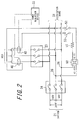
- FIG. 2 is a diagram illustrating the wiring relating to the dummy output system 50.
- the grid is in the single-phase three-wire form of 200 V.
- one voltage line and a neutral line are connected to the dummy output system 50 at the output unit 26 via the transformer 60.
- the connection line to the dummy output system 50 is arranged to pass through the current sensor 40 placed in each of the two voltage lines, as illustrated in the drawing.
- the dummy output system 50 may be integral with the power control device 20, or independent of the power control device 20.
- the dummy current load 51 is a load provided as appropriate for current adjustment in the dummy output system 50.
- the dummy current load 51 may be a load outside the dummy output system 50.
- the synchronous switch 52 is used to supply, to the current sensor 40, part of the power supplied from the power control device 20 or the power generation device 33 to the dummy output system 50, as the dummy current in the same direction as forward power flow.
- the dummy current control switch 53 prevents unnecessary power generation caused by the dummy current.
- the synchronous switch 52 and the dummy current control switch 53 are each composed of an independent relay, transistor, or the like, and independently controlled to be on or off by the controller 25 in the power control device 20.
- the transformer 60 has a function of stepping down the power from the power control device 20 or the power generation device 33.
- the transformer 60 has a turn ratio of 20, and steps down the AC power of 100 V from the power control device 20 or the power generation device 33 to AC power of 5 V and supplies the power to the dummy current load 51.
- the transformer 60 By supplying the power stepped down by the transformer 60 to the dummy current load 51 in this way, the power consumption in the dummy current load 51 is reduced and the voltages for the switches 52 and 53 are reduced. This allows less expensive products to be used for the dummy current load 51 and the switches 52 and 53.
- the synchronous switch 52 is controlled to be on or off synchronously with the isolated operation switch 24 in the power control device 20.
- the synchronous switch 52 is off during grid-connected operation and on during isolated operation, as with the isolated operation switch 24.
- the synchronous switch 52 is a switch whose switching is synchronous with the switching between paralleling off from the grid and paralleling to the grid, and causes the dummy current to flow during paralleling off from the grid and causes the dummy current not to flow during paralleling to the grid.
- the synchronous control of the isolated operation switch 24 and the synchronous switch 52 is realized in terms of hardware by making the control signal wiring to the isolated operation switch 24 branch to the synchronous switch 52.
- the synchronous control of the isolated operation switch 24 and the synchronous switch 52 may be realized in terms of software by the controller 25.
- the dummy current control switch 53 is off in the case where the charging of the storage battery 12 has been completed, and on in the case where the charging has not been completed.
- the case where the charging of the storage battery 12 has been completed indicates the case where the storage battery 12 is charged with a predetermined amount of power or more.
- the controller 25 may be configured to determine whether or not the charging has been completed, by communicating with the storage battery 12. When the charging of the storage battery 12 is completed and the dummy current control switch 53 is turned off during isolated operation, the dummy current stops flowing to the current sensor 40. This prevents unnecessary power generation by the power generation device 33.
- FIG. 3 is a diagram illustrating an example of control in the power control system 100 during grid-connected operation.
- the switches in the power control device 20 are controlled as follows: The grid-connected operation switches 22 and 23 are on, and the isolated operation switch 24 is off.
- the switches in the dummy output system 50 are controlled as follows: The synchronous switch 52 is off, and the dummy current control switch 53 is on or off according to the amount of charge in the storage battery 12.
- AC power of 100 V (or 200 V) is supplied from the grid to the load 32, as indicated by the thick arrow in FIG. 3 .
- the power control device 20 converts the AC power from the grid into DC power, and charges the storage battery 12 with the DC power.
- the power control device 20 may also convert the power generated by the solar cell 11 into AC power and cause the power to reversely flow to the grid, or sell surplus power.
- the power control device 20 has a structure capable of outputting the power from the grid and the power from each distributed power source (the solar cell 11, the storage battery 12) to the dummy output system 50, the synchronous switch 52 is off during grid-connected operation, and therefore the dummy current is not supplied to the current sensor 40.
- the current sensor 40 detects forward power flow (current in the power purchase direction) from the grid, so that the power generation device 33 generates power and supplies the power to the load 32 via the distribution board 31.
- FIGS. 4 and 5 An example of control in the power control system 100 during isolated operation is described below, with reference to FIGS. 4 and 5 .
- the switches in the power control device 20 are controlled as follows: The grid-connected operation switches 22 and 23 are off, and the isolated operation switch 24 is on.
- the switches in the dummy output system 50 are controlled as follows: The synchronous switch 52 is on, and the dummy current control switch 53 is on.
- FIG. 4 is a diagram illustrating power supply by each distributed power source during isolated operation.
- the power control device 20 outputs the power of each distributed power source (the solar cell 11, the storage battery 12) to the load 32 and the dummy output system 50 via the isolated operation switch 24.
- the current sensor 40 detects forward power flow (current in the power purchase direction).
- the power generation device 33 in this embodiment is configured to start generating power only in the case where the current sensor 40 detects forward power flow not less than a predetermined threshold, in order to prevent the generated power from reversely flowing to the grid.
- FIG. 4 illustrates the state where the current sensor 40 detects only forward power flow less than the predetermined threshold, and only the solar cell 11 supplies power to the load 32.
- FIG. 5 is a diagram illustrating the power generation of the power generation device 33 according to the dummy current during isolated operation.
- the power generation device 33 supplies power to the dummy output system 50, as illustrated in FIG. 5 .
- the power supplied to the dummy output system 50 passes through the transformer 60, and is supplied to the current sensor 40 as the dummy current.
- the current sensor 40 detects forward power flow (current in the power purchase direction) not less than the predetermined threshold
- the power generation device 33 generates power in load following operation or rated operation.
- the distribution board 31 supplies the power generated by the power generation device 33 to the load 32, and supplies any surplus power over the power consumption of the load 32 to the power control device 20.
- the surplus power passes through the isolated operation switch 24 and is converted into DC power by the inverter 21 in the power control device 20, and is fed to the storage battery 12.
- the power control system 100 includes the dummy output system 50 configured to supply power from the power generation device 33 or any other distributed power sources (the solar cell 11, the storage battery 12) in the state where the power generation device 33 and the other distributed power sources are paralleled off from the grid, and can supply the dummy current which is a current in the same direction as forward power flow to the current sensor 40 using the output from the dummy output system 50.
- the flow of the dummy current to the current sensor 40 can cause the power generation device 33 to generate power during isolated operation. Since the power generation of the power generation device 33 is controlled using the dummy current to the current sensor 40, there is no need to specially change the power generation device 33 itself. This has the advantage that a general-purpose fuel cell system and gas power generation system can be utilized.
- the power is supplied from the power control device 20 or the power generation device 33 to the dummy current load 51 in the dummy output system 50 via the transformer 60.
- the power consumption in the dummy current load 51 in the case of supplying the same dummy current to the current sensor 40 is reduced, and also the voltages for the switches 52 and 53 are reduced. This allows less expensive products to be used for the dummy current load 51 and the switches 52 and 53.
- the synchronous switch 52 is a switch whose switching is synchronous with the switching between paralleling off from the grid and paralleling to the grid, and causes the dummy current to flow during paralleling off from the grid and causes the dummy current not to flow during paralleling to the grid.
- the dummy current flows to the current sensor 40 during isolated operation where the power generation device 33 and the other distributed power sources are paralleled off from the grid.
- the dummy current does not flow to the current sensor 40 during grid-connected operation where the power generation device 33 and the other distributed power sources are paralleled to the grid, thus suppressing erroneous reverse power flow from the power generation device 33.
- the isolated operation switch 24 is off during grid-connected operation and on during isolated operation by the distributed power sources, and is located between the power generation device 33 and the other distributed power sources (the solar cell 11, the storage battery 12). Hence, the power generated by the power generation device 33 can be supplied to the other distributed power sources via the isolated operation switch 24 during isolated operation.
- the storage battery 12 is chargeable with the power from the power generation device 33 when the isolated operation switch 24 is on. Accordingly, for example, surplus power generated by the power generation device 33 over the power consumption of the load 32 may be stored in the storage battery 12 during isolated operation.
- FIG. 6 is a diagram illustrating an example of control in the power control system 100 during isolated operation after the completion of the charging of the storage battery 12.
- the switches in the power control device 20 are controlled as follows: The grid-connected operation switches 22 and 23 are off, and the isolated operation switch 24 is on.
- the switches in the dummy output system are controlled as follows: The synchronous switch 52 is on, and the dummy current control switch 53 is off.
- the dummy current control switch 53 is off. Hence, part of the power supplied from the power control device 20 or the power generation device 33 to the dummy output system 50 is not supplied to the current sensor 40 as the dummy current in isolated operation.
- the current sensor 40 therefore detects neither the forward power flow from the grid nor the dummy current, and so the power generation device 33 stops generating power. This prevents excessive current output to the storage battery 12.
- the storage battery 12 starts discharging, as illustrated in FIG. 6 .
- the power from the storage battery 12 is supplied to the load 32 via the inverter 21, the isolated operation switch 24, and the like.
- the power control device 20 turns on the dummy current control switch 53 again.
- the dummy current flows to the current sensor 40 again, and the power generation device 33 starts generating power to charge the storage battery 12 again.
- the dummy current control switch 53 stops the dummy current when the charging of the storage battery 12 is completed, with it being possible to prevent excessive power generation by the power generation device 33.
- the current sensor 40 is preferably placed in a position where the current by the power generation of the power generation device 33 does not flow during isolated operation in the power control device 20, as illustrated in FIGS. 1 to 6 . If the current sensor 40 is placed in a position where the current by the power generation of the power generation device 33 flows, the dummy current for causing the power generation device 33 to generate power needs to exceed the current by the power generation, which leads to an increase in power consumption relating to the dummy current. By placing the current sensor 40 in a position where the current by the power generation of the power generation device 33 does not flow during isolated operation in the power control device 20, the power consumption relating to the dummy current can be reduced.
- Embodiment 2 A power control system according to Embodiment 2 is described next, mainly focusing on the differences from Embodiment 1.
- the current sensor 40 is located between the isolated operation switch 24 and the distribution board 31, to be capable of detecting the current flowing between the grid and the power generation device 33 and the current flowing between the power generation device 33 and the storage battery 12.
- the dummy current load 51 and the dummy current control switch 53 are connected in series.
- the synchronous switch 52 and the dummy current control switch 53 are both on, the dummy current flows through the dummy current load 51.
- FIG. 9 is a diagram illustrating the connection between the current sensor 40 and each of a power line 61 and a dummy output line 62.
- the power line 61 from the grid and each distributed power source passes through the center of the ring-shaped current sensor 40, and the dummy output line 62 from the dummy output system is wound around the current sensor 40 a predetermined number of turns. More winding of the dummy output line 62 around the current sensor 40 enables the detection of larger current in the forward power flow direction using small dummy current.
- the transformer 60 has a function of stepping down the power from the power control device 20 or the power generation device 33.
- the transformer 60 has a turn ratio of 20, and steps down the AC power of 100 V from the power control device 20 or the power generation device 33 to AC power of 5 V and supplies the power to the dummy current load 51.
- the power consumption in the dummy current load 51 is reduced, which allows the dummy current load 51 to be downsized.
- the voltages for the switches 52 and 53 are reduced, which allows less expensive products to be used for the switches 52 and 53.
- larger dummy current can be caused to flow with the same power consumption in the dummy current load 51.
- the synchronous switch 52 is controlled to be on or off synchronously with the isolated operation switch 24 in the power control device 20.
- the synchronous switch 52 is off during grid-connected operation and on during isolated operation, as with the isolated operation switch 24.
- the synchronous switch 52 is a switch whose switching is synchronous with the switching between paralleling off from the grid and paralleling to the grid, and causes the dummy current to flow during paralleling off from the grid and causes the dummy current not to flow during paralleling to the grid.
- the synchronous control of the isolated operation switch 24 and the synchronous switch 52 is realized in terms of hardware by making the control signal wiring to the isolated operation switch 24 branch to the synchronous switch 52.
- the synchronous control of the isolated operation switch 24 and the synchronous switch 52 may be realized in terms of software by the controller 25.
- the dummy current control switch 53 is off in the case where the charging of the storage battery 12 has been completed, and on in the case where the charging has not been completed.
- the case where the charging of the storage battery 12 has been completed indicates the case where the storage battery 12 is charged with a predetermined amount of power or more.
- the controller 25 may be configured to determine whether or not the charging has been completed, by communicating with the storage battery 12. When the charging of the storage battery 12 is completed and the dummy current control switch 53 is turned off during isolated operation, the dummy current stops flowing to the current sensor 40. This prevents unnecessary power generation by the power generation device 33.
- the power generation device 33 in the power control system according to this embodiment has rated power of 700 W.
- the current sensor 40 detects current in the reverse power flow direction equivalent to the output power of 700 W.
- the power control device 20 or the power generation device 33 supplies power to the dummy output system 50, and the dummy output system 50 causes dummy current for canceling out the current in the reverse power flow direction detected by the current sensor 40 to flow.
- the dummy output system needs to generate at least dummy current equivalent to output power of 735 W, in order to ensure that the current sensor always detects forward power flow.
- the method of determining the resistance R 1 of the dummy current load 51 for generating the dummy current I 1 is described bellow. As illustrated in FIG. 8 , one voltage line and a neutral line are connected to the dummy output system 50, and the AC voltage of 100 V is stepped down to AC power of 5 V by the transformer 60 and then supplied to the dummy output system 50.
- the dummy current I 1 and the resistance R 1 calculated in the aforementioned manner are merely an example, and various parameters may be selected depending on the number of turns of the dummy output line 62, the dummy current (equivalent output power) to be supplied to the current sensor, etc.
- FIG. 10 is a diagram illustrating an example of control in the power control system 100 during grid-connected operation.
- the switches in the power control device 20 are controlled as follows: The grid-connected operation switches 22 and 23 are on, and the isolated operation switch 24 is off.
- the switches in the dummy output system 50 are controlled as follows: The synchronous switch 52 is off, and the dummy current control switch 53 is on or off according to the amount of charge in the storage battery 12.
- AC power of 100 V (or 200 V) is supplied from the grid to the load 32, as indicated by the thick arrow in FIG. 10 .
- the power control device 20 converts AC power from the grid into DC power, and charges the storage battery 12 with the DC power.
- the power control device 20 may also convert the power generated by the solar cell 11 into AC power and cause the power to reversely flow to the grid, or sell surplus power.
- the power control device 20 has a structure configured to output the power from the grid and the power from each distributed power source (the solar cell 11, the storage battery 12) to the dummy output system 50, the synchronous switch 52 is off during grid-connected operation, and therefore the dummy current is not supplied to the current sensor 40.
- the current sensor 40 detects forward power flow (current in the power purchase direction) from the grid, so that the power generation device 33 generates power and supplies the power to the load 32 via the distribution board 31.
- FIGS. 11 and 12 An example of control in the power control system 100 during isolated operation is described below, with reference to FIGS. 11 and 12 .
- the switches in the power control device 20 are controlled as follows: The grid-connected operation switches 22 and 23 are off, and the isolated operation switch 24 is on.
- the switches in the dummy output system 50 are controlled as follows: The synchronous switch 52 is on, and the dummy current control switch 53 is on.
- FIG. 11 is a diagram illustrating power supply by each distributed power source during isolated operation.
- the power control device 20 outputs the power of each distributed power source (the solar cell 11, the storage battery 12) to the load 32 and the dummy output system 50 via the isolated operation switch 24.
- the current sensor 40 detects forward power flow (current in the power purchase direction).
- the power generation device 33 in this embodiment is configured to start generating power only in the case where the current sensor 40 detects forward power flow not less than a predetermined threshold, in order to prevent the generated power from reversely flowing to the grid.
- FIG. 11 illustrates the state where the current sensor 40 detects only forward power flow less than the predetermined threshold, and only the solar cell 11 supplies power to the load 32.
- FIG. 12 is a flowchart of the operation of the power control system from when the power generation device starts charging the storage battery to when the power generation device ends the charging.
- the controller 25 determines whether or not the storage battery 12 is fully charged (step S601). In the case of determining that the storage battery 12 is not fully charged, the controller 25 turns the dummy current control switch 53 on (step S602).
- the power control system 100 accordingly shifts to the state where the storage battery 12 is chargeable from the power generation device 33 as illustrated in FIG. 13 .
- FIG. 13 is a diagram illustrating the power generation of the power generation device 33 according to the dummy current during isolated operation.
- the power generation device 33 supplies power to the dummy output system 50, as illustrated in FIG. 13 .
- the power supplied to the dummy output system 50 passes through the transformer 60, and is supplied to the current sensor 40 as the dummy current.
- the dummy output system 50 operates so that the current sensor 40 detects forward power flow (current in the power purchase direction) not less than the predetermined threshold, as a result of which the power generation device 33 generates power in load following operation or rated operation.
- the distribution board 31 supplies the power generated by the power generation device 33 to the load 32, and supplies any surplus power over the power consumption of the load 32 to the power control device 20.
- the surplus power passes through the isolated operation switch 24 and is converted into DC power by the inverter 21 in the power control device 20, and is fed to the storage battery 12.
- the power control system 100 includes the dummy output system 50 configured to supply power from the power generation device 33 or any other distributed power sources (the solar cell 11, the storage battery 12) in the state where the power generation device 33 and the other distributed power sources are paralleled off from the grid, and can supply the dummy current which is a current in the same direction as forward power flow to the current sensor 40 using the output from the dummy output system 50.
- the flow of the dummy current to the current sensor 40 can intentionally cause the power generation device 33 to perform rated power generation during isolated operation. Since the power generation of the power generation device 33 is controlled using the dummy current to the current sensor 40, there is no need to specially change the power generation device 33 itself. This has the advantage that a general-purpose fuel cell system and gas power generation system can be utilized.
- the power is supplied from the power control device 20 or the power generation device 33 to the dummy current load 51 in the dummy output system 50 via the transformer 60.
- the power consumption in the dummy current load 51 in the case of supplying the same dummy current to the current sensor 40 is reduced, which allows the dummy current load 51 to be downsized.
- the voltages for the switches 52 and 53 are reduced, which allows less expensive products to be used for the switches 52 and 53.
- larger dummy current can be caused to flow with the same power consumption in the dummy current load 51. Therefore, even in the case where the power generation device 33 generates larger power, larger dummy current for canceling out the detection of current in the reverse power flow direction can be caused to flow.
- the synchronous switch 52 is a switch whose switching is synchronous with the switching between paralleling off from the grid and paralleling to the grid, and causes the dummy current to flow during paralleling off from the grid and causes the dummy current not to flow during paralleling to the grid.
- the dummy current flows to the current sensor 40 during isolated operation where the power generation device 33 and the other distributed power sources are paralleled off from the grid.
- the dummy current does not flow to the current sensor 40 during grid-connected operation where the power generation device 33 and the other distributed power sources are paralleled to the grid, thus suppressing erroneous reverse power flow from the power generation device 33.
- the isolated operation switch 24 is off during grid-connected operation and on during isolated operation by the distributed power sources, and is located between the power generation device 33 and the other distributed power sources (the solar cell 11, the storage battery 12). Hence, the power generated by the power generation device 33 can be supplied to the other distributed power source via the isolated operation switch 24 during isolated operation.
- the storage battery 12 is chargeable with the power from the power generation device 33 when the isolated operation switch 24 is on. Accordingly, for example, surplus power generated by the power generation device 33 over the power consumption of the load 32 may be stored in the storage battery 12 during isolated operation.
- step S603 in the case where the controller 25 determines that the storage battery 12 is fully charged (step S603), the controller 25 turns the dummy current control switch 53 off (step S604).
- the power control system 100 accordingly shifts to the state after the completion of the charging as illustrated in FIG. 14 .
- FIG. 14 is a diagram illustrating an example of control in the power control system 100 during isolated operation after the completion of the charging of the storage battery 12.
- the switches in the power control device 20 are controlled as follows: The grid-connected operation switches 22 and 23 are off, and the isolated operation switch 24 is on.
- the switches in the dummy output system 50 are controlled as follows: The synchronous switch 52 is on, and the dummy current control switch 53 is off.
- the dummy current control switch 53 is off. Hence, part of the power supplied from the power control device 20 or the power generation device 33 to the dummy output system 50 is not supplied to the current sensor 40 as the dummy current in isolated operation.
- the current sensor 40 detects the current in the forward power flow direction supplied from the storage battery 12 to the load 32, and the power generation device 33 performs load following operation of supplying power to the load.
- the power discharged from the storage battery 12 is supplied to the load 32 via the inverter 21, the isolated operation switch 24, and the like.
- the power control device 20 turns on the dummy current control switch 53 again.
- the dummy current flows to the current sensor 40 again, and the power generation device 33 is switched from load following operation to rated operation to charge the storage battery 12 again.
- the dummy current control switch 53 stops the dummy current when the charging of the storage battery 12 is completed, with it being possible to prevent excessive power generation by the power generation device 33.
- the current sensor 40 is located between the isolated operation switch 24 and the power generation device 33 as illustrated in FIG. 7 , to also enable the detection of current in the direction from the power generation device 33 to the other distributed power sources in the isolated operation mode.
- the power generation device 33 can be caused to perform load following operation in the isolated operation mode.
- the controller 25 may check the detection of current in the current sensor 40 by increasing or decreasing the power generated from the power generation device 33.
- the foregoing embodiments describe the case where the synchronous switch 52 and the dummy current control switch 53 are each an independent switch that is switched according to a separate condition, these switches may be combined together. In detail, these switches may be configured as one switch that is on only during isolated operation and during charging. Although the foregoing embodiments describe an example where the synchronous switch 52 and the dummy current control switch 53 are located on the secondary side of the transformer, these switches may be located on the primary side of the transformer. In the case where the switches are located on the primary side, no current flows through the transformer and so losses in the transformer can be avoided.
- Examples of the at least one processor executing logical blocks, program modules, or the like include at least one microprocessor, central processing unit (CPU), application specific integrated circuit (ASIC), digital signal processor (DSP), programmable logic device (PLD), field programmable gate array (FPGA), processor, controller, microcontroller, microprocessor, electronic device, other devices designed to execute the functions described herein, and/or any combination thereof.
- the embodiments described herein are implemented, for example, by hardware, software, firmware, middleware, microcode, or any combination thereof. Instructions may be program code or code segments for performing necessary tasks, and may be stored in a non-transitory machine-readable storage medium or other medium.
- a code segment may represent a procedure, a function, a subprogram, a program, a routine, a subroutine, a module, a software package, a class, or any combination of instructions, data structures, or program statements.
- a code segment is connected to another code segment or a hardware circuit, by performing transmission and/or reception of information, data arguments, variables, or storage contents with the other code segment or hardware circuit.
- Examples of the network used herein include, unless otherwise specified, the Internet, an ad hoc network, a local area network (LAN), a cellular network, a wireless personal area network (WPAN), other networks, or any combination thereof.
- the components of the wireless network include, for example, an access point (e.g. Wi-Fi access point) and a femtocell.
- the wireless communicator may be connected to a wireless network using Wi-Fi, Bluetooth® (Bluetooth is a registered trademark in Japan, other countries, or both), cellular communication technology (e.g.
- CDMA Code Division Multiple Access
- TDMA Time Division Multiple Access
- FDMA Frequency Division Multiple Access
- OFDMA Orthogonal Frequency Division Multiple Access
- SC-FDMA Single-Carrier Frequency Division Multiple Access
- the non-transitory machine-readable storage medium used herein may be in any tangible form of computer-readable carrier (medium) in the categories of solid-state memory, magnetic disk, and optical disk. Such a medium stores an appropriate set of computer instructions, such as program modules, and data structures for causing a processor to carry out the techniques disclosed herein. Examples of the computer-readable medium include an electrical connection having one or more wires, a magnetic disk storage medium, a magnetic cassette, magnetic tape, other magnetic and optical storage devices (e.g.
- CD compact disk
- LaserDisc® LaserDisc is a registered trademark in Japan, other countries, or both
- DVD® digital versatile disc
- Floppy® Floppy is a registered trademark in Japan, other countries, or both
- Blu-ray Disc® Blu-ray Disc is a registered trademark in Japan, other countries, or both
- RAM random access memory
- ROM read-only memory
- EPROM EPROM
- EEPROM electrically erasable programmable ROM
- flash memory other tangible storage medium capable of storage, and any combination thereof.
- Memory may be provided inside and/or outside a processor/processing unit.
- the term "memory” used herein indicates any type of memory such as long-term storage, short-term storage, volatile, nonvolatile, and other memory, and the number of memory media or the types of media are not limited.
- modules and/or units for executing specific functions. These modules and units are schematically illustrated to simplify the description of its functionality, and do not necessarily represent specific hardware and/or software.
- the modules, units, and other components may be hardware and/or software implemented to substantially execute the specific functions described herein.
- Various functions of different components may be any combination or separate ones of hardware and/or software, and may be used separately or in combination.
- I/O devices or user interfaces including, but not limited to, a keyboard, a display, a touchscreen, and a pointing device may be connected to the system directly or via intervening I/O controllers.
- I/O Input/output
- the disclosed various aspects may be embodied in many different forms, and all such embodiments are within the scope of the disclosure.
Landscapes
- Engineering & Computer Science (AREA)
- Power Engineering (AREA)
- Business, Economics & Management (AREA)
- Emergency Management (AREA)
- Supply And Distribution Of Alternating Current (AREA)
- Charge And Discharge Circuits For Batteries Or The Like (AREA)
- Stand-By Power Supply Arrangements (AREA)
Abstract
Description
- This application claims priority to Japanese Patent Application No.
2014-9916 filed on January 22, 2014 2014-14939 filed on January 29, 2014 - The disclosure relates to a power control system and a control method of a power control system.
- A known power control device for a power generation system including a power generation facility such as a solar panel is capable of grid-connected operation of outputting AC power in connection with a commercial electric power grid (hereafter abbreviated to "grid" as appropriate) and isolated operation of outputting AC power independently of the grid (for example, see Patent Literature (PTL) 1).
- A known power control device for a power storage system including a power storage facility such as a storage battery charged with grid power is capable of grid-connected operation of outputting AC power in connection with a grid and isolated operation of outputting AC power independently of the grid (for example, see PTL 2), as with the aforementioned power control device.
-
- PTL 1:
JP 2007-049770 A - PTL 2:
JP 2008-253033 A - There has been demand for a power control system that collectively manages and operates a plurality of distributed power sources such as a solar cell, a storage battery, a fuel cell, and a gas power generator. In particular, there has been demand to establish a system capable of efficient operation control between a plurality of distributed power sources without undermining the versatility of the distributed power sources.
- It could therefore be helpful to provide a power control system capable of efficient operation control between a plurality of distributed power sources without undermining the versatility of the distributed power sources, and a control method of the power control system.
- A power control system according to the disclosure is a power control system that controls a power generation device and other distributed power sources, the power generation device generating power while a current sensor detects forward power flow, the power control system including: a power control device including an output unit configured to output power supplied from the other distributed power sources, in a state where the power generation device and the other distributed power sources are paralleled off from a grid; and a dummy output system configured to supply a dummy current detectable by the current sensor as a current in the same direction as the forward power flow, using an output from the output unit, wherein the dummy output system includes step-down means located between the output unit and the current sensor.
- A control method of a power control system according to the disclosure is a control method of a power control system that is provided in a consumer's facility and performs power control, the consumer's facility including a power generation device and other distributed power sources, the power generation device generating power while a current sensor detects forward power flow, the control method including: outputting power supplied from the other distributed power sources, in a state where the power generation device and the other distributed power sources are paralleled off from a grid; stepping down the power supplied from the other distributed power sources; and supplying a dummy current detectable by the current sensor as a current in the same direction as the forward power flow, using the stepped down power.
- It is possible to provide a power control system capable of efficient operation control between a plurality of distributed power sources without undermining the versatility of the distributed power sources, and a control method of the power control system.
- In the accompanying drawings:
-
FIG. 1 is a block diagram of a power control system according toEmbodiment 1; -
FIG. 2 is a diagram illustrating wiring relating to a dummy output system according toEmbodiment 1; -
FIG. 3 is a diagram illustrating an example of control in the power control system according toEmbodiment 1 during grid-connected operation; -
FIG. 4 is a diagram illustrating an example of control in the power control system according toEmbodiment 1 during isolated operation (power generation by a solar cell); -
FIG. 5 is a diagram illustrating an example of control in the power control system according toEmbodiment 1 during isolated operation (power generation by a power generation device); -
FIG. 6 is a diagram illustrating an example of control in the power control system according toEmbodiment 1 during isolated operation (after the completion of charging of a storage battery); -
FIG. 7 is a block diagram of a power control system according to Embodiment 2; -
FIG. 8 is a diagram illustrating wiring relating to a dummy output system according to Embodiment 2; -
FIG. 9 is a diagram illustrating wiring between a current sensor and each of a power line and the dummy output system in the power control system according to Embodiment 2; -
FIG. 10 is a diagram illustrating an example of control in the power control system according to Embodiment 2 during grid-connected operation; -
FIG. 11 is a diagram illustrating an example of control in the power control system according to Embodiment 2 during isolated operation (power generation by a solar cell); -
FIG. 12 is a flowchart of the operation of the power control system according to Embodiment 2 from when a power generation device starts charging a storage battery to when the power generation device ends the charging; -
FIG. 13 is a diagram illustrating an example of control in the power control system according to Embodiment 2 during isolated operation (power generation by the power generation device); and -
FIG. 14 is a diagram illustrating an example of control in the power control system according to Embodiment 2 during isolated operation (after the completion of charging of the storage battery). - The following describes disclosed embodiments in detail with reference to drawings.
- A power control system according to
Embodiment 1 is described first. Apower control system 100 according to this embodiment includes a distributed power source that supplies sellable power and/or a distributed power source that supplies unsellable power, apart from power supplied from a grid (commercial electric power grid). Examples of the distributed power source that supplies sellable power include a system for supplying power by solar power generation or the like. Examples of the distributed power sources that supplies unsellable power include a storage battery system that can be charged and discharged, a fuel cell system including a fuel cell such as a solid oxide fuel cell (SOFC), and a gas power generation system for generating power using gas fuel. This embodiment describes an example of including a solar cell as a distributed power source that supplies sellable power and a storage battery and a power generation device such as a fuel cell or a gas power generator as distributed power sources that supply unsellable power. -
FIG. 1 is a block diagram illustrating the schematic structure of thepower control system 100 according toEmbodiment 1. Thepower control system 100 according to this embodiment includes a power control device 20 (power control device) and adummy output system 50.FIG. 1 also illustrates asolar cell 11, astorage battery 12, adistribution board 31, aload 32, and apower generation device 33 that are connected to thepower control system 100. Thepower generation device 33 is a device including a fuel cell or a gas power generator. Thepower control system 100 normally performs grid-connected operation, to supply power from the grid and power from each distributed power source (thesolar cell 11, thestorage battery 12, the power generation device 33) to theload 32. In the case where no power is supplied from the grid due to a power failure or the like, thepower control system 100 performs isolated operation to supply power from each distributed power source (thesolar cell 11, thestorage battery 12, the power generation device 33) to each load (theload 32, a dummy current load 51). When thepower control system 100 performs isolated operation, each distributed power source (thesolar cell 11, thestorage battery 12, the power generation device 33) is paralleled off from the grid. When thepower control system 100 performs grid-connected operation, each distributed power source (thesolar cell 11, thestorage battery 12, the power generation device 33) is paralleled to the grid. - In
FIG. 1 , the solid lines between the functional blocks represent wiring through which power flows, and the dotted lines between the functional blocks represent the flow of control signals or information communicated. The communication represented by the dotted lines may be wired communication or wireless communication. Various schemes are available for the communication of information and control signals, including each layer. For example, the communication may be performed by a short-range communication scheme such as ZigBee® (ZigBee is a registered trademark in Japan, other countries, or both). The communication may also be performed using various transmission media such as infrared communication and power line communication (PLC). Moreover, any of various communication protocols defining the logical layer, such as ZigBee SEP 2.0 (Smart Energy Profile 2.0) and ECHONET Lite® (ECHONET Lite is a registered trademark in Japan, other countries, or both), may be operated on lower layers including the physical layer suitable for each communication. - The
solar cell 11 converts energy from sunlight into electric power. For example, thesolar cell 11 is formed by connecting power generators having photoelectric conversion cells in a matrix to output a predetermined current (e.g. 10 A). The type of thesolar cell 11 is not limited as long as it is capable of photoelectric conversion, such as a polycrystalline silicon solar cell, a monocrystalline silicon solar cell, or a thin-film solar cell of CIGS or the like. - The
storage battery 12 is a storage battery such as a lithium ion battery or a nickel-metal-hydride battery. Thestorage battery 12 may be discharged to supply power. Thestorage battery 12 is chargeable with not only power supplied from the grid or thesolar cell 11 but also power supplied from thepower generation device 33 as described later. - The
power control device 20 converts DC power supplied from thesolar cell 11 and thestorage battery 12 and AC power supplied from the grid and thepower generation device 33, and also controls the switching between grid-connected operation and isolated operation. Thepower control device 20 includes aninverter 21, grid-connectedoperation switches isolated operation switch 24, and acontroller 25 that controls the overallpower control device 20. Thepower control device 20 also includes an output unit 26 (seeFIG. 2 ) for supplying AC power to thedummy output system 50 described later. The grid-connectedoperation switch 23 may be located outside thepower control device 20. - The
inverter 21 is a bidirectional inverter, and converts DC power supplied from thesolar cell 11 and thestorage battery 12 into AC power and AC power supplied from the grid and thepower generation device 33 into DC power. A converter for stepping up the DC power from thesolar cell 11 and thestorage battery 12 to a predetermined voltage may be provided at a stage preceding theinverter 21. - The grid-connected operation switches 22 and 23 and the
isolated operation switch 24 are each composed of a relay, a transistor, or the like, and controlled to be on or off. Theisolated operation switch 24 is located between thepower generation device 33 and thestorage battery 12, as illustrated in the drawing. The grid-connected operation switches 22 and 23 and theisolated operation switch 24 are switched synchronously so that the grid-connected operation switches 22 and 23 and theisolated operation switch 24 are not on (or off) simultaneously. In more detail, when the grid-connected operation switches 22 and 23 are on, theisolated operation switch 24 is off synchronously. When the grid-connected operation switches 22 and 23 are off, theisolated operation switch 24 is on synchronously. The synchronous control of the grid-connected operation switches 22 and 23 and theisolated operation switch 24 is realized in terms of hardware by making the control signal wiring to the grid-connected operation switches 22 and 23 branch to theisolated operation switch 24. Here, the on/off state in response to the same control signal may be set independently for each switch. The synchronous control of the grid-connected operation switches 22 and 23 and theisolated operation switch 24 may be realized in terms of software by thecontroller 25. - The
controller 25 is composed of a microcomputer as an example, and controls the operation of each of theinverter 21, grid-connected operation switches 22 and 23,isolated operation switch 24, etc. based on the state of a grid voltage increase, a power failure, and the like. During grid-connected operation, thecontroller 25 turns the grid-connected operation switches 22 and 23 on and theisolated operation switch 24 off. During isolated operation, thecontroller 25 turns the grid-connected operation switches 22 and 23 off and theisolated operation switch 24 on. - The
distribution board 31 separates the power supplied from the grid during grid-connected operation into a plurality of branches and distributes the power to theload 32. Thedistribution board 31 also separates the power supplied from the plurality of distributed power sources (thesolar cell 11, thestorage battery 12, the power generation device 33) into a plurality of branches and distributes the power to theload 32. Theload 32 is an electric power load that consumes power. Examples of theload 32 include various electric products for home use such as an air conditioner, a microwave, and a television, and machines, lighting systems, etc. for use in industrial and commercial installations such as an air conditioner and a lighting fixture. - The
power generation device 33 includes a fuel cell or a gas power generator. The fuel cell includes a cell that generates DC power using hydrogen through a chemical reaction with oxygen in the air, an inverter that converts the generated DC power into AC power of 100 V or 200 V, and other auxiliaries. The fuel cell as thepower generation device 33 is a system configured to supply AC power to theload 32 without involving thepower control device 20, and is not necessarily designed based on the assumption that it is connected to thepower control device 20. The fuel cell may thus be a versatile system. The gas power generator generates power by a gas engine that uses a predetermined gas or the like as fuel. - The
power generation device 33 generates power while the correspondingcurrent sensor 40 detects forward power flow (current, in the power purchase direction). When generating power, thepower generation device 33 performs load following operation of following the power consumption of theload 32 or rated operation at predetermined rated power. For example, the range of following in load following operation is 200 W to 700 W, and the rated power in rated operation is 700 W. Thepower generation device 33 may perform load following operation of following the power consumption of theload 32 during grid-connected operation, and perform load following operation or rated operation at rated power during isolated operation. - The
current sensor 40 detects the current flowing between the grid and thepower generation device 33. In Japan, the power generated by thepower generation device 33 is unsellable. Accordingly, in the case where thecurrent sensor 40 detects reverse power flow (current in the power selling direction) to the grid, thepower generation device 33 stops generating power. While thecurrent sensor 40 detects forward power flow, thepower generation device 33 generates power in load following operation or rated operation on the ground that thepower generation device 33 can supply power to theload 32. To reduce power consumption, thecurrent sensor 40 is preferably placed in a position where the current by the power generation of thepower generation device 33 does not flow during isolated operation in thepower control device 20, as described later. - The
power control system 100 in this embodiment performs such control that causes a dummy current in the same direction as forward power flow to flow to thecurrent sensor 40 through thedummy output system 50, in the state where thepower generation device 33 and thestorage battery 12 are paralleled off from the grid. This causes thepower generation device 33 to perform rated operation, so that the power generated by thepower generation device 33 can be stored in thestorage battery 12. The power storage using the dummy current through thedummy output system 50 is described in detail below. - The
dummy output system 50 is configured to supply the dummy current, which is a current in the same direction as forward power flow, to thecurrent sensor 40. Thedummy output system 50 is supplied with power from theoutput unit 26 in thepower control device 20 or thepower generation device 33, and includes the dummycurrent load 51, asynchronous switch 52, a dummycurrent control switch 53, and atransformer 60.FIG. 2 is a diagram illustrating the wiring relating to thedummy output system 50. InFIG. 2 , the grid is in the single-phase three-wire form of 200 V. In this case, one voltage line and a neutral line are connected to thedummy output system 50 at theoutput unit 26 via thetransformer 60. The connection line to thedummy output system 50 is arranged to pass through thecurrent sensor 40 placed in each of the two voltage lines, as illustrated in the drawing. Thedummy output system 50 may be integral with thepower control device 20, or independent of thepower control device 20. - The dummy
current load 51 is a load provided as appropriate for current adjustment in thedummy output system 50. The dummycurrent load 51 may be a load outside thedummy output system 50. Thesynchronous switch 52 is used to supply, to thecurrent sensor 40, part of the power supplied from thepower control device 20 or thepower generation device 33 to thedummy output system 50, as the dummy current in the same direction as forward power flow. The dummycurrent control switch 53 prevents unnecessary power generation caused by the dummy current. Thesynchronous switch 52 and the dummycurrent control switch 53 are each composed of an independent relay, transistor, or the like, and independently controlled to be on or off by thecontroller 25 in thepower control device 20. - The
transformer 60 has a function of stepping down the power from thepower control device 20 or thepower generation device 33. In this embodiment, thetransformer 60 has a turn ratio of 20, and steps down the AC power of 100 V from thepower control device 20 or thepower generation device 33 to AC power of 5 V and supplies the power to the dummycurrent load 51. By supplying the power stepped down by thetransformer 60 to the dummycurrent load 51 in this way, the power consumption in the dummycurrent load 51 is reduced and the voltages for theswitches current load 51 and theswitches - The
synchronous switch 52 is controlled to be on or off synchronously with theisolated operation switch 24 in thepower control device 20. In other words, thesynchronous switch 52 is off during grid-connected operation and on during isolated operation, as with theisolated operation switch 24. In more detail, thesynchronous switch 52 is a switch whose switching is synchronous with the switching between paralleling off from the grid and paralleling to the grid, and causes the dummy current to flow during paralleling off from the grid and causes the dummy current not to flow during paralleling to the grid. The synchronous control of theisolated operation switch 24 and thesynchronous switch 52 is realized in terms of hardware by making the control signal wiring to theisolated operation switch 24 branch to thesynchronous switch 52. The synchronous control of theisolated operation switch 24 and thesynchronous switch 52 may be realized in terms of software by thecontroller 25. - The dummy
current control switch 53 is off in the case where the charging of thestorage battery 12 has been completed, and on in the case where the charging has not been completed. The case where the charging of thestorage battery 12 has been completed indicates the case where thestorage battery 12 is charged with a predetermined amount of power or more. Thecontroller 25 may be configured to determine whether or not the charging has been completed, by communicating with thestorage battery 12. When the charging of thestorage battery 12 is completed and the dummycurrent control switch 53 is turned off during isolated operation, the dummy current stops flowing to thecurrent sensor 40. This prevents unnecessary power generation by thepower generation device 33. - The following describes an example of control in the power control system according to this embodiment in detail, with reference to drawings.
-
FIG. 3 is a diagram illustrating an example of control in thepower control system 100 during grid-connected operation. In this case, the switches in thepower control device 20 are controlled as follows: The grid-connected operation switches 22 and 23 are on, and theisolated operation switch 24 is off. Moreover, the switches in thedummy output system 50 are controlled as follows: Thesynchronous switch 52 is off, and the dummycurrent control switch 53 is on or off according to the amount of charge in thestorage battery 12. - During grid-connected operation, AC power of 100 V (or 200 V) is supplied from the grid to the
load 32, as indicated by the thick arrow inFIG. 3 . In the case where the charging of thestorage battery 12 has not been completed, thepower control device 20 converts the AC power from the grid into DC power, and charges thestorage battery 12 with the DC power. Thepower control device 20 may also convert the power generated by thesolar cell 11 into AC power and cause the power to reversely flow to the grid, or sell surplus power. Although thepower control device 20 has a structure capable of outputting the power from the grid and the power from each distributed power source (thesolar cell 11, the storage battery 12) to thedummy output system 50, thesynchronous switch 52 is off during grid-connected operation, and therefore the dummy current is not supplied to thecurrent sensor 40. Thecurrent sensor 40 detects forward power flow (current in the power purchase direction) from the grid, so that thepower generation device 33 generates power and supplies the power to theload 32 via thedistribution board 31. - An example of control in the
power control system 100 during isolated operation is described below, with reference toFIGS. 4 and5 . InFIGS. 4 and5 , the charging of thestorage battery 12 has not been completed. In this case, the switches in thepower control device 20 are controlled as follows: The grid-connected operation switches 22 and 23 are off, and theisolated operation switch 24 is on. Moreover, the switches in thedummy output system 50 are controlled as follows: Thesynchronous switch 52 is on, and the dummycurrent control switch 53 is on. -
FIG. 4 is a diagram illustrating power supply by each distributed power source during isolated operation. During isolated operation, thepower control device 20 outputs the power of each distributed power source (thesolar cell 11, the storage battery 12) to theload 32 and thedummy output system 50 via theisolated operation switch 24. InFIG. 4 , as a result of thepower control device 20 supplying the power to thedummy output system 50, thecurrent sensor 40 detects forward power flow (current in the power purchase direction). Thepower generation device 33 in this embodiment is configured to start generating power only in the case where thecurrent sensor 40 detects forward power flow not less than a predetermined threshold, in order to prevent the generated power from reversely flowing to the grid.FIG. 4 illustrates the state where thecurrent sensor 40 detects only forward power flow less than the predetermined threshold, and only thesolar cell 11 supplies power to theload 32. -
FIG. 5 is a diagram illustrating the power generation of thepower generation device 33 according to the dummy current during isolated operation. In the case where thepower generation device 33 generates power during isolated operation, thepower generation device 33 supplies power to thedummy output system 50, as illustrated inFIG. 5 . The power supplied to thedummy output system 50 passes through thetransformer 60, and is supplied to thecurrent sensor 40 as the dummy current. When thecurrent sensor 40 detects forward power flow (current in the power purchase direction) not less than the predetermined threshold, thepower generation device 33 generates power in load following operation or rated operation. Thedistribution board 31 supplies the power generated by thepower generation device 33 to theload 32, and supplies any surplus power over the power consumption of theload 32 to thepower control device 20. The surplus power passes through theisolated operation switch 24 and is converted into DC power by theinverter 21 in thepower control device 20, and is fed to thestorage battery 12. - Thus, according to this embodiment, the
power control system 100 includes thedummy output system 50 configured to supply power from thepower generation device 33 or any other distributed power sources (thesolar cell 11, the storage battery 12) in the state where thepower generation device 33 and the other distributed power sources are paralleled off from the grid, and can supply the dummy current which is a current in the same direction as forward power flow to thecurrent sensor 40 using the output from thedummy output system 50. This enables efficient operation control between a plurality of distributed power sources without undermining the versatility of the distributed power sources. In more detail, the flow of the dummy current to thecurrent sensor 40 can cause thepower generation device 33 to generate power during isolated operation. Since the power generation of thepower generation device 33 is controlled using the dummy current to thecurrent sensor 40, there is no need to specially change thepower generation device 33 itself. This has the advantage that a general-purpose fuel cell system and gas power generation system can be utilized. - According to this embodiment, the power is supplied from the
power control device 20 or thepower generation device 33 to the dummycurrent load 51 in thedummy output system 50 via thetransformer 60. With such a structure, the power consumption in the dummycurrent load 51 in the case of supplying the same dummy current to thecurrent sensor 40 is reduced, and also the voltages for theswitches current load 51 and theswitches - According to this embodiment, the
synchronous switch 52 is a switch whose switching is synchronous with the switching between paralleling off from the grid and paralleling to the grid, and causes the dummy current to flow during paralleling off from the grid and causes the dummy current not to flow during paralleling to the grid. Hence, the dummy current flows to thecurrent sensor 40 during isolated operation where thepower generation device 33 and the other distributed power sources are paralleled off from the grid. On the other hand, the dummy current does not flow to thecurrent sensor 40 during grid-connected operation where thepower generation device 33 and the other distributed power sources are paralleled to the grid, thus suppressing erroneous reverse power flow from thepower generation device 33. - According to this embodiment, the
isolated operation switch 24 is off during grid-connected operation and on during isolated operation by the distributed power sources, and is located between thepower generation device 33 and the other distributed power sources (thesolar cell 11, the storage battery 12). Hence, the power generated by thepower generation device 33 can be supplied to the other distributed power sources via theisolated operation switch 24 during isolated operation. - The
storage battery 12 is chargeable with the power from thepower generation device 33 when theisolated operation switch 24 is on. Accordingly, for example, surplus power generated by thepower generation device 33 over the power consumption of theload 32 may be stored in thestorage battery 12 during isolated operation. -
FIG. 6 is a diagram illustrating an example of control in thepower control system 100 during isolated operation after the completion of the charging of thestorage battery 12. In this case, the switches in thepower control device 20 are controlled as follows: The grid-connected operation switches 22 and 23 are off, and theisolated operation switch 24 is on. Moreover, the switches in the dummy output system are controlled as follows: Thesynchronous switch 52 is on, and the dummycurrent control switch 53 is off. - In the case where the charging of the
storage battery 12 has been completed, the dummycurrent control switch 53 is off. Hence, part of the power supplied from thepower control device 20 or thepower generation device 33 to thedummy output system 50 is not supplied to thecurrent sensor 40 as the dummy current in isolated operation. Thecurrent sensor 40 therefore detects neither the forward power flow from the grid nor the dummy current, and so thepower generation device 33 stops generating power. This prevents excessive current output to thestorage battery 12. - Once the charging of the
storage battery 12 has been completed, thestorage battery 12 starts discharging, as illustrated inFIG. 6 . The power from thestorage battery 12 is supplied to theload 32 via theinverter 21, theisolated operation switch 24, and the like. When the discharge is continued for a predetermined time and the amount of charge in thestorage battery 12 falls below a threshold, thepower control device 20 turns on the dummycurrent control switch 53 again. As a result of this control, the dummy current flows to thecurrent sensor 40 again, and thepower generation device 33 starts generating power to charge thestorage battery 12 again. - Thus, according to this embodiment, the dummy
current control switch 53 stops the dummy current when the charging of thestorage battery 12 is completed, with it being possible to prevent excessive power generation by thepower generation device 33. - The
current sensor 40 is preferably placed in a position where the current by the power generation of thepower generation device 33 does not flow during isolated operation in thepower control device 20, as illustrated inFIGS. 1 to 6 . If thecurrent sensor 40 is placed in a position where the current by the power generation of thepower generation device 33 flows, the dummy current for causing thepower generation device 33 to generate power needs to exceed the current by the power generation, which leads to an increase in power consumption relating to the dummy current. By placing thecurrent sensor 40 in a position where the current by the power generation of thepower generation device 33 does not flow during isolated operation in thepower control device 20, the power consumption relating to the dummy current can be reduced. - A power control system according to Embodiment 2 is described next, mainly focusing on the differences from
Embodiment 1. - In
FIG. 7 , thecurrent sensor 40 is located between theisolated operation switch 24 and thedistribution board 31, to be capable of detecting the current flowing between the grid and thepower generation device 33 and the current flowing between thepower generation device 33 and thestorage battery 12. - As illustrated in
FIGS. 7 and8 , the dummycurrent load 51 and the dummycurrent control switch 53 are connected in series. When thesynchronous switch 52 and the dummycurrent control switch 53 are both on, the dummy current flows through the dummycurrent load 51. -
FIG. 9 is a diagram illustrating the connection between thecurrent sensor 40 and each of apower line 61 and adummy output line 62. Thepower line 61 from the grid and each distributed power source passes through the center of the ring-shapedcurrent sensor 40, and thedummy output line 62 from the dummy output system is wound around the current sensor 40 a predetermined number of turns. More winding of thedummy output line 62 around thecurrent sensor 40 enables the detection of larger current in the forward power flow direction using small dummy current. - The
transformer 60 has a function of stepping down the power from thepower control device 20 or thepower generation device 33. In this embodiment, thetransformer 60 has a turn ratio of 20, and steps down the AC power of 100 V from thepower control device 20 or thepower generation device 33 to AC power of 5 V and supplies the power to the dummycurrent load 51. By supplying the power stepped down by thetransformer 60 to the dummycurrent load 51 in this way, the power consumption in the dummycurrent load 51 is reduced, which allows the dummycurrent load 51 to be downsized. In addition, the voltages for theswitches switches current load 51. - The
synchronous switch 52 is controlled to be on or off synchronously with theisolated operation switch 24 in thepower control device 20. In other words, thesynchronous switch 52 is off during grid-connected operation and on during isolated operation, as with theisolated operation switch 24. In more detail, thesynchronous switch 52 is a switch whose switching is synchronous with the switching between paralleling off from the grid and paralleling to the grid, and causes the dummy current to flow during paralleling off from the grid and causes the dummy current not to flow during paralleling to the grid. The synchronous control of theisolated operation switch 24 and thesynchronous switch 52 is realized in terms of hardware by making the control signal wiring to theisolated operation switch 24 branch to thesynchronous switch 52. The synchronous control of theisolated operation switch 24 and thesynchronous switch 52 may be realized in terms of software by thecontroller 25. - The dummy
current control switch 53 is off in the case where the charging of thestorage battery 12 has been completed, and on in the case where the charging has not been completed. The case where the charging of thestorage battery 12 has been completed indicates the case where thestorage battery 12 is charged with a predetermined amount of power or more. Thecontroller 25 may be configured to determine whether or not the charging has been completed, by communicating with thestorage battery 12. When the charging of thestorage battery 12 is completed and the dummycurrent control switch 53 is turned off during isolated operation, the dummy current stops flowing to thecurrent sensor 40. This prevents unnecessary power generation by thepower generation device 33. - The following describes the setting of the dummy current value in this embodiment. The
power generation device 33 in the power control system according to this embodiment has rated power of 700 W. InFIGS. 7 and8 , if thepower generation device 33 outputs power of 700 W, thecurrent sensor 40 detects current in the reverse power flow direction equivalent to the output power of 700 W. - In view of this, in this embodiment, the
power control device 20 or thepower generation device 33 supplies power to thedummy output system 50, and thedummy output system 50 causes dummy current for canceling out the current in the reverse power flow direction detected by thecurrent sensor 40 to flow. For example, when the detection error in the current sensor is 35 W in terms of output power, the dummy output system needs to generate at least dummy current equivalent to output power of 735 W, in order to ensure that the current sensor always detects forward power flow. - In this embodiment, suppose dummy current equivalent to output power of 800 W which is greater than 735 W is generated. When the output voltage of the distributed power sources is AC power of 200 V and the number of turns of the
dummy output line 62 wound around the current sensor is 8, the dummy current I1 to be generated by the dummy output system is calculated as follows:
- The method of determining the resistance R1 of the dummy
current load 51 for generating the dummy current I1 is described bellow. As illustrated inFIG. 8 , one voltage line and a neutral line are connected to thedummy output system 50, and the AC voltage of 100 V is stepped down to AC power of 5 V by thetransformer 60 and then supplied to thedummy output system 50. The resistance R1 for generating the dummy current I1 is accordingly calculated as follows:
- The dummy current I1 and the resistance R1 calculated in the aforementioned manner are merely an example, and various parameters may be selected depending on the number of turns of the
dummy output line 62, the dummy current (equivalent output power) to be supplied to the current sensor, etc. - The following describes an example of control in the power control system according to this embodiment in detail, with reference to drawings.
-
FIG. 10 is a diagram illustrating an example of control in thepower control system 100 during grid-connected operation. In this case, the switches in thepower control device 20 are controlled as follows: The grid-connected operation switches 22 and 23 are on, and theisolated operation switch 24 is off. Moreover, the switches in thedummy output system 50 are controlled as follows: Thesynchronous switch 52 is off, and the dummycurrent control switch 53 is on or off according to the amount of charge in thestorage battery 12. - During grid-connected operation, AC power of 100 V (or 200 V) is supplied from the grid to the
load 32, as indicated by the thick arrow inFIG. 10 . In the case where the charging of thestorage battery 12 has not been completed, thepower control device 20 converts AC power from the grid into DC power, and charges thestorage battery 12 with the DC power. Thepower control device 20 may also convert the power generated by thesolar cell 11 into AC power and cause the power to reversely flow to the grid, or sell surplus power. Although thepower control device 20 has a structure configured to output the power from the grid and the power from each distributed power source (thesolar cell 11, the storage battery 12) to thedummy output system 50, thesynchronous switch 52 is off during grid-connected operation, and therefore the dummy current is not supplied to thecurrent sensor 40. Thecurrent sensor 40 detects forward power flow (current in the power purchase direction) from the grid, so that thepower generation device 33 generates power and supplies the power to theload 32 via thedistribution board 31. - An example of control in the
power control system 100 during isolated operation is described below, with reference toFIGS. 11 and12 . InFIGS. 11 and12 , the charging of thestorage battery 12 has not been completed. In this case, the switches in thepower control device 20 are controlled as follows: The grid-connected operation switches 22 and 23 are off, and theisolated operation switch 24 is on. Moreover, the switches in thedummy output system 50 are controlled as follows: Thesynchronous switch 52 is on, and the dummycurrent control switch 53 is on. -
FIG. 11 is a diagram illustrating power supply by each distributed power source during isolated operation. During isolated operation, thepower control device 20 outputs the power of each distributed power source (thesolar cell 11, the storage battery 12) to theload 32 and thedummy output system 50 via theisolated operation switch 24. InFIG. 11 , as a result of thepower control device 20 supplying the power to thedummy output system 50, thecurrent sensor 40 detects forward power flow (current in the power purchase direction). Thepower generation device 33 in this embodiment is configured to start generating power only in the case where thecurrent sensor 40 detects forward power flow not less than a predetermined threshold, in order to prevent the generated power from reversely flowing to the grid.FIG. 11 illustrates the state where thecurrent sensor 40 detects only forward power flow less than the predetermined threshold, and only thesolar cell 11 supplies power to theload 32. - The following describes the case of charging the
storage battery 12 from thepower generation device 33.FIG. 12 is a flowchart of the operation of the power control system from when the power generation device starts charging the storage battery to when the power generation device ends the charging. Thecontroller 25 determines whether or not thestorage battery 12 is fully charged (step S601). In the case of determining that thestorage battery 12 is not fully charged, thecontroller 25 turns the dummycurrent control switch 53 on (step S602). Thepower control system 100 accordingly shifts to the state where thestorage battery 12 is chargeable from thepower generation device 33 as illustrated inFIG. 13 . -
FIG. 13 is a diagram illustrating the power generation of thepower generation device 33 according to the dummy current during isolated operation. In the case where thepower generation device 33 generates power during isolated operation, thepower generation device 33 supplies power to thedummy output system 50, as illustrated inFIG. 13 . The power supplied to thedummy output system 50 passes through thetransformer 60, and is supplied to thecurrent sensor 40 as the dummy current. Thedummy output system 50 operates so that thecurrent sensor 40 detects forward power flow (current in the power purchase direction) not less than the predetermined threshold, as a result of which thepower generation device 33 generates power in load following operation or rated operation. Thedistribution board 31 supplies the power generated by thepower generation device 33 to theload 32, and supplies any surplus power over the power consumption of theload 32 to thepower control device 20. The surplus power passes through theisolated operation switch 24 and is converted into DC power by theinverter 21 in thepower control device 20, and is fed to thestorage battery 12. - Thus, according to this embodiment, the
power control system 100 includes thedummy output system 50 configured to supply power from thepower generation device 33 or any other distributed power sources (thesolar cell 11, the storage battery 12) in the state where thepower generation device 33 and the other distributed power sources are paralleled off from the grid, and can supply the dummy current which is a current in the same direction as forward power flow to thecurrent sensor 40 using the output from thedummy output system 50. This enables efficient operation control between a plurality of distributed power sources without undermining the versatility of the distributed power sources. In more detail, the flow of the dummy current to thecurrent sensor 40 can intentionally cause thepower generation device 33 to perform rated power generation during isolated operation. Since the power generation of thepower generation device 33 is controlled using the dummy current to thecurrent sensor 40, there is no need to specially change thepower generation device 33 itself. This has the advantage that a general-purpose fuel cell system and gas power generation system can be utilized. - According to this embodiment, the power is supplied from the
power control device 20 or thepower generation device 33 to the dummycurrent load 51 in thedummy output system 50 via thetransformer 60. With such a structure, the power consumption in the dummycurrent load 51 in the case of supplying the same dummy current to thecurrent sensor 40 is reduced, which allows the dummycurrent load 51 to be downsized. In addition, the voltages for theswitches switches current load 51. Therefore, even in the case where thepower generation device 33 generates larger power, larger dummy current for canceling out the detection of current in the reverse power flow direction can be caused to flow. - According to this embodiment, the
synchronous switch 52 is a switch whose switching is synchronous with the switching between paralleling off from the grid and paralleling to the grid, and causes the dummy current to flow during paralleling off from the grid and causes the dummy current not to flow during paralleling to the grid. Hence, the dummy current flows to thecurrent sensor 40 during isolated operation where thepower generation device 33 and the other distributed power sources are paralleled off from the grid. On the other hand, the dummy current does not flow to thecurrent sensor 40 during grid-connected operation where thepower generation device 33 and the other distributed power sources are paralleled to the grid, thus suppressing erroneous reverse power flow from thepower generation device 33. - According to this embodiment, the
isolated operation switch 24 is off during grid-connected operation and on during isolated operation by the distributed power sources, and is located between thepower generation device 33 and the other distributed power sources (thesolar cell 11, the storage battery 12). Hence, the power generated by thepower generation device 33 can be supplied to the other distributed power source via theisolated operation switch 24 during isolated operation. - The
storage battery 12 is chargeable with the power from thepower generation device 33 when theisolated operation switch 24 is on. Accordingly, for example, surplus power generated by thepower generation device 33 over the power consumption of theload 32 may be stored in thestorage battery 12 during isolated operation. - In
FIG. 12 , in the case where thecontroller 25 determines that thestorage battery 12 is fully charged (step S603), thecontroller 25 turns the dummycurrent control switch 53 off (step S604). Thepower control system 100 accordingly shifts to the state after the completion of the charging as illustrated inFIG. 14 . -
FIG. 14 is a diagram illustrating an example of control in thepower control system 100 during isolated operation after the completion of the charging of thestorage battery 12. In this case, the switches in thepower control device 20 are controlled as follows: The grid-connected operation switches 22 and 23 are off, and theisolated operation switch 24 is on. Moreover, the switches in thedummy output system 50 are controlled as follows: Thesynchronous switch 52 is on, and the dummycurrent control switch 53 is off. - In the case where the charging of the
storage battery 12 has been completed, the dummycurrent control switch 53 is off. Hence, part of the power supplied from thepower control device 20 or thepower generation device 33 to thedummy output system 50 is not supplied to thecurrent sensor 40 as the dummy current in isolated operation. Here, thecurrent sensor 40 detects the current in the forward power flow direction supplied from thestorage battery 12 to theload 32, and thepower generation device 33 performs load following operation of supplying power to the load. - In
FIG. 14 , the power discharged from thestorage battery 12 is supplied to theload 32 via theinverter 21, theisolated operation switch 24, and the like. When the discharge is continued for a predetermined time and the amount of charge in thestorage battery 12 falls below a threshold, thepower control device 20 turns on the dummycurrent control switch 53 again. As a result of this control, the dummy current flows to thecurrent sensor 40 again, and thepower generation device 33 is switched from load following operation to rated operation to charge thestorage battery 12 again. - Thus, according to this embodiment, the dummy
current control switch 53 stops the dummy current when the charging of thestorage battery 12 is completed, with it being possible to prevent excessive power generation by thepower generation device 33. - According to this embodiment, the
current sensor 40 is located between theisolated operation switch 24 and thepower generation device 33 as illustrated inFIG. 7 , to also enable the detection of current in the direction from thepower generation device 33 to the other distributed power sources in the isolated operation mode. With such a structure, thepower generation device 33 can be caused to perform load following operation in the isolated operation mode. Moreover, in the case where thepower generation device 33 is charging thestorage battery 12, thecontroller 25 may check the detection of current in thecurrent sensor 40 by increasing or decreasing the power generated from thepower generation device 33. - Although the foregoing embodiments describe the case where the
solar cell 11, thestorage battery 12, and thepower generation device 33 are not included in thepower control system 100, these distributed power sources may be included in thepower control system 100. - Although the foregoing embodiments describe the case where the
synchronous switch 52 and the dummycurrent control switch 53 are each an independent switch that is switched according to a separate condition, these switches may be combined together. In detail, these switches may be configured as one switch that is on only during isolated operation and during charging. Although the foregoing embodiments describe an example where thesynchronous switch 52 and the dummycurrent control switch 53 are located on the secondary side of the transformer, these switches may be located on the primary side of the transformer. In the case where the switches are located on the primary side, no current flows through the transformer and so losses in the transformer can be avoided. - Although the disclosed system and method have been described by way of the drawings and embodiments, various changes or modifications may be easily made by those of ordinary skill in the art based on the disclosure. Such various changes or modifications are therefore included in the scope of the disclosure. For example, the functions included in the members, means, steps, etc. may be rearranged without logical inconsistency, and a plurality of means, steps, etc. may be combined into one means, step, etc. and a means, step, etc. may be divided into a plurality of means, steps, etc.
- Many of the disclosed aspects are described in terms of sequences of operations performed by a computer system or other hardware capable of executing program instructions. Examples of the computer system or other hardware include a general-purpose computer, a personal computer (PC), a dedicated computer, a workstation, a personal communications system (PCS), a RFID receiver, an electronic notepad, a laptop computer, a global positioning system (GPS) receiver, and other programmable data processors. Note that, in each embodiment, various operations are executed by dedicated circuitry (e.g. discrete logical gates interconnected to realize specific functions) implemented by program instructions (software) or logical blocks, program modules, or the like executed by at least one processor. Examples of the at least one processor executing logical blocks, program modules, or the like include at least one microprocessor, central processing unit (CPU), application specific integrated circuit (ASIC), digital signal processor (DSP), programmable logic device (PLD), field programmable gate array (FPGA), processor, controller, microcontroller, microprocessor, electronic device, other devices designed to execute the functions described herein, and/or any combination thereof. The embodiments described herein are implemented, for example, by hardware, software, firmware, middleware, microcode, or any combination thereof. Instructions may be program code or code segments for performing necessary tasks, and may be stored in a non-transitory machine-readable storage medium or other medium. A code segment may represent a procedure, a function, a subprogram, a program, a routine, a subroutine, a module, a software package, a class, or any combination of instructions, data structures, or program statements. A code segment is connected to another code segment or a hardware circuit, by performing transmission and/or reception of information, data arguments, variables, or storage contents with the other code segment or hardware circuit.
- Examples of the network used herein include, unless otherwise specified, the Internet, an ad hoc network, a local area network (LAN), a cellular network, a wireless personal area network (WPAN), other networks, or any combination thereof. The components of the wireless network include, for example, an access point (e.g. Wi-Fi access point) and a femtocell. The wireless communicator may be connected to a wireless network using Wi-Fi, Bluetooth® (Bluetooth is a registered trademark in Japan, other countries, or both), cellular communication technology (e.g. Code Division Multiple Access (CDMA), Time Division Multiple Access (TDMA), Frequency Division Multiple Access (FDMA), Orthogonal Frequency Division Multiple Access (OFDMA), Single-Carrier Frequency Division Multiple Access (SC-FDMA)), or any other wireless technology and/or technological standard.
- The non-transitory machine-readable storage medium used herein may be in any tangible form of computer-readable carrier (medium) in the categories of solid-state memory, magnetic disk, and optical disk. Such a medium stores an appropriate set of computer instructions, such as program modules, and data structures for causing a processor to carry out the techniques disclosed herein. Examples of the computer-readable medium include an electrical connection having one or more wires, a magnetic disk storage medium, a magnetic cassette, magnetic tape, other magnetic and optical storage devices (e.g. compact disk (CD), LaserDisc® (LaserDisc is a registered trademark in Japan, other countries, or both), digital versatile disc (DVD® (DVD is a registered trademark in Japan, other countries, or both)), Floppy® (Floppy is a registered trademark in Japan, other countries, or both)) disk, Blu-ray Disc® (Blu-ray Disc is a registered trademark in Japan, other countries, or both)), a portable computer disk, random access memory (RAM), read-only memory (ROM), EPROM, EEPROM, flash memory, other rewritable and programmable ROM, other tangible storage medium capable of storage, and any combination thereof. Memory may be provided inside and/or outside a processor/processing unit. The term "memory" used herein indicates any type of memory such as long-term storage, short-term storage, volatile, nonvolatile, and other memory, and the number of memory media or the types of media are not limited.
- It should be noted that the system is disclosed herein as having various modules and/or units for executing specific functions. These modules and units are schematically illustrated to simplify the description of its functionality, and do not necessarily represent specific hardware and/or software. In this regard, the modules, units, and other components may be hardware and/or software implemented to substantially execute the specific functions described herein. Various functions of different components may be any combination or separate ones of hardware and/or software, and may be used separately or in combination. Input/output (I/O) devices or user interfaces including, but not limited to, a keyboard, a display, a touchscreen, and a pointing device may be connected to the system directly or via intervening I/O controllers. Thus, the disclosed various aspects may be embodied in many different forms, and all such embodiments are within the scope of the disclosure.
-
- 11
- solar cell
- 12
- storage battery
- 20
- power control device
- 21
- inverter
- 22, 23
- grid-connected operation switch
- 24
- isolated operation switch
- 25
- controller
- 26
- output unit
- 31
- distribution board
- 32
- load
- 33
- power generation device
- 40
- current sensor
- 50
- dummy output system
- 51
- dummy current load
- 52
- synchronous switch
- 53
- dummy current control switch
- 60
- transformer
- 61
- power line
- 62
- dummy output line
- 100
- power control system
Claims (8)
- A power control system that controls a power generation device and other distributed power sources, the power generation device generating power while a current sensor detects forward power flow, the power control system comprising:a power control device including an output unit configured to output power supplied from the other distributed power sources, in a state where the power generation device and the other distributed power sources are paralleled off from a grid; anda dummy output system configured to supply a dummy current detectable by the current sensor as a current in the same direction as the forward power flow, using an output from the output unit,wherein the dummy output system includes step-down means located between the output unit and the current sensor.
- The power control system according to claim 1,
wherein the dummy output system is also configured to supply the dummy current using an output from the power generation device, and the step-down means is also located between the power generation device and the current sensor. - The power control system according to claim 1,
wherein the current sensor is placed in a position where a current flowing between the grid and the power generation device and a current flowing between the power generation device and the other distributed power sources are detectable. - The power control system according to any one of claims 1 to 3,
wherein the step-down means is a transformer. - The power control system according to any one of claims 1 to 4,
wherein the dummy output system further includes switching means for selecting whether or not to cause the dummy current to flow. - The power control system according to any one of claims 1 to 5,
wherein the power generation device includes a fuel cell. - The power control system according to any one of claims 1 to 6,
wherein the power generation device starts generating power when the current sensor detects the current not less than a predetermined threshold in the same direction as the forward power flow. - A control method of a power control system that is provided in a consumer's facility and performs power control, the consumer's facility including a power generation device and other distributed power sources, the power generation device generating power while a current sensor detects forward power flow, the control method including:outputting power supplied from the other distributed power sources, in a state where the power generation device and the other distributed power sources are paralleled off from a grid;stepping down the power supplied from the other distributed power sources; andsupplying a dummy current detectable by the current sensor as a current in the same direction as the forward power flow, using the stepped down power.
Applications Claiming Priority (3)
| Application Number | Priority Date | Filing Date | Title |
|---|---|---|---|
| JP2014009916 | 2014-01-22 | ||
| JP2014014939 | 2014-01-29 | ||
| PCT/JP2015/000293 WO2015111410A1 (en) | 2014-01-22 | 2015-01-22 | Power control system and method for controlling power control system |
Publications (3)
| Publication Number | Publication Date |
|---|---|
| EP3098928A1 true EP3098928A1 (en) | 2016-11-30 |
| EP3098928A4 EP3098928A4 (en) | 2017-06-21 |
| EP3098928B1 EP3098928B1 (en) | 2018-07-18 |
Family
ID=53681220
Family Applications (1)
| Application Number | Title | Priority Date | Filing Date |
|---|---|---|---|
| EP15740623.2A Active EP3098928B1 (en) | 2014-01-22 | 2015-01-22 | Power control system and method for controlling power control system |
Country Status (4)
| Country | Link |
|---|---|
| US (1) | US10211635B2 (en) |
| EP (1) | EP3098928B1 (en) |
| JP (1) | JP6170183B2 (en) |
| WO (1) | WO2015111410A1 (en) |
Cited By (3)
| Publication number | Priority date | Publication date | Assignee | Title |
|---|---|---|---|---|
| EP3361595A1 (en) * | 2017-02-10 | 2018-08-15 | Florindo William Di Giulio | Apparatus to accumulate and supply electric energy to a user device |
| EP3370320A4 (en) * | 2015-10-28 | 2019-03-20 | Kyocera Corporation | Power control system and control method for power control system |
| IT201900001231A1 (en) * | 2019-01-28 | 2020-07-28 | Davide Giacomo Piccinin | System and method for managing an exchange of electricity between two electricity networks |
Families Citing this family (4)
| Publication number | Priority date | Publication date | Assignee | Title |
|---|---|---|---|---|
| CN103762714B (en) * | 2014-01-13 | 2018-03-13 | 深圳市泰永电气科技有限公司 | A kind of switching device for being used to realize multiple power-supply system switching controls |
| US10847847B2 (en) | 2015-09-29 | 2020-11-24 | Kyocera Corporation | Power source apparatus, distributed power source system, and control method thereof |
| KR101906886B1 (en) * | 2016-05-11 | 2018-10-11 | 엘에스산전 주식회사 | Energy storage device |
| JP7184487B2 (en) * | 2019-04-16 | 2022-12-06 | トヨタホーム株式会社 | building power supply system |
Family Cites Families (8)
| Publication number | Priority date | Publication date | Assignee | Title |
|---|---|---|---|---|
| JPH11262198A (en) * | 1998-03-13 | 1999-09-24 | Furukawa Electric Co Ltd:The | Protector for moving body |
| JP2007049770A (en) | 2005-08-05 | 2007-02-22 | Toshiba Kyaria Kk | Power supply |
| JP4979435B2 (en) | 2007-03-30 | 2012-07-18 | 新電元工業株式会社 | Power storage device |
| US9606520B2 (en) | 2009-06-22 | 2017-03-28 | Johnson Controls Technology Company | Automated fault detection and diagnostics in a building management system |
| US9071141B2 (en) * | 2011-04-08 | 2015-06-30 | Virginia Tech Intellectual Properties, Inc. | Two-stage single phase bi-directional PWM power converter with DC link capacitor reduction |
| JP2012249476A (en) | 2011-05-30 | 2012-12-13 | Panasonic Corp | Power supply system |
| JP5878393B2 (en) | 2012-02-17 | 2016-03-08 | 大和ハウス工業株式会社 | Power supply system |
| KR20130138611A (en) * | 2012-06-11 | 2013-12-19 | 삼성에스디아이 주식회사 | Energy storage system |
-
2015
- 2015-01-22 WO PCT/JP2015/000293 patent/WO2015111410A1/en active Application Filing
- 2015-01-22 EP EP15740623.2A patent/EP3098928B1/en active Active
- 2015-01-22 JP JP2015558784A patent/JP6170183B2/en active Active
- 2015-01-22 US US15/113,419 patent/US10211635B2/en active Active
Cited By (3)
| Publication number | Priority date | Publication date | Assignee | Title |
|---|---|---|---|---|
| EP3370320A4 (en) * | 2015-10-28 | 2019-03-20 | Kyocera Corporation | Power control system and control method for power control system |
| EP3361595A1 (en) * | 2017-02-10 | 2018-08-15 | Florindo William Di Giulio | Apparatus to accumulate and supply electric energy to a user device |
| IT201900001231A1 (en) * | 2019-01-28 | 2020-07-28 | Davide Giacomo Piccinin | System and method for managing an exchange of electricity between two electricity networks |
Also Published As
| Publication number | Publication date |
|---|---|
| EP3098928B1 (en) | 2018-07-18 |
| WO2015111410A1 (en) | 2015-07-30 |
| US10211635B2 (en) | 2019-02-19 |
| US20170012428A1 (en) | 2017-01-12 |
| EP3098928A4 (en) | 2017-06-21 |
| JPWO2015111410A1 (en) | 2017-03-23 |
| JP6170183B2 (en) | 2017-07-26 |
Similar Documents
| Publication | Publication Date | Title |
|---|---|---|
| US10211635B2 (en) | Power control system and control method of power control system | |
| JP6334037B2 (en) | Power conversion apparatus, power conversion apparatus control method, and power conversion system | |
| JP6246917B2 (en) | Power supply system, control method for power supply system, and power supply apparatus | |
| JP6227885B2 (en) | Power control system, power control apparatus, and control method for power control system | |
| WO2016067603A1 (en) | Power supply device, power supply system, and method for controlling power supply device | |
| JP6251288B2 (en) | Power control system, power control apparatus, and control method for power control system | |
| JP6216066B2 (en) | Power control system control method, power control system, and power control apparatus | |
| EP3136536B1 (en) | Power control device, power control method, and power control system | |
| JP2016092850A (en) | Control method of power supply system, power supply apparatus and power supply system | |
| JP6582113B2 (en) | Power control apparatus, power control system, and control method for power control system | |
| JP6694930B2 (en) | Power control system control method, power control system, and power control device | |
| JP6704479B2 (en) | POWER SUPPLY SYSTEM, POWER SUPPLY DEVICE, AND POWER SUPPLY SYSTEM CONTROL METHOD | |
| JP6731417B2 (en) | Power control system and control method of power control system | |
| JP6475286B2 (en) | Power control apparatus, power control system, and control method for power control system |
Legal Events
| Date | Code | Title | Description |
|---|---|---|---|
| PUAI | Public reference made under article 153(3) epc to a published international application that has entered the european phase |
Free format text: ORIGINAL CODE: 0009012 |
|
| 17P | Request for examination filed |
Effective date: 20160714 |
|
| AK | Designated contracting states |
Kind code of ref document: A1 Designated state(s): AL AT BE BG CH CY CZ DE DK EE ES FI FR GB GR HR HU IE IS IT LI LT LU LV MC MK MT NL NO PL PT RO RS SE SI SK SM TR |
|
| AX | Request for extension of the european patent |
Extension state: BA ME |
|
| DAX | Request for extension of the european patent (deleted) | ||
| A4 | Supplementary search report drawn up and despatched |
Effective date: 20170519 |
|
| RIC1 | Information provided on ipc code assigned before grant |
Ipc: H02J 7/35 20060101ALI20170515BHEP Ipc: H02M 7/44 20060101ALI20170515BHEP Ipc: H02J 3/38 20060101AFI20170515BHEP Ipc: H02J 7/00 20060101ALI20170515BHEP Ipc: H02J 9/06 20060101ALI20170515BHEP |
|
| GRAP | Despatch of communication of intention to grant a patent |
Free format text: ORIGINAL CODE: EPIDOSNIGR1 |
|
| STAA | Information on the status of an ep patent application or granted ep patent |
Free format text: STATUS: GRANT OF PATENT IS INTENDED |
|
| INTG | Intention to grant announced |
Effective date: 20180212 |
|
| GRAS | Grant fee paid |
Free format text: ORIGINAL CODE: EPIDOSNIGR3 |
|
| GRAA | (expected) grant |
Free format text: ORIGINAL CODE: 0009210 |
|
| STAA | Information on the status of an ep patent application or granted ep patent |
Free format text: STATUS: THE PATENT HAS BEEN GRANTED |
|
| AK | Designated contracting states |
Kind code of ref document: B1 Designated state(s): AL AT BE BG CH CY CZ DE DK EE ES FI FR GB GR HR HU IE IS IT LI LT LU LV MC MK MT NL NO PL PT RO RS SE SI SK SM TR |
|
| REG | Reference to a national code |
Ref country code: GB Ref legal event code: FG4D |
|
| REG | Reference to a national code |
Ref country code: CH Ref legal event code: EP |
|
| REG | Reference to a national code |
Ref country code: IE Ref legal event code: FG4D |
|
| REG | Reference to a national code |
Ref country code: AT Ref legal event code: REF Ref document number: 1020394 Country of ref document: AT Kind code of ref document: T Effective date: 20180815 |
|
| REG | Reference to a national code |
Ref country code: DE Ref legal event code: R096 Ref document number: 602015013764 Country of ref document: DE |
|
| REG | Reference to a national code |
Ref country code: NL Ref legal event code: MP Effective date: 20180718 |
|
| REG | Reference to a national code |
Ref country code: LT Ref legal event code: MG4D |
|
| REG | Reference to a national code |
Ref country code: AT Ref legal event code: MK05 Ref document number: 1020394 Country of ref document: AT Kind code of ref document: T Effective date: 20180718 |
|
| PG25 | Lapsed in a contracting state [announced via postgrant information from national office to epo] |
Ref country code: NL Free format text: LAPSE BECAUSE OF FAILURE TO SUBMIT A TRANSLATION OF THE DESCRIPTION OR TO PAY THE FEE WITHIN THE PRESCRIBED TIME-LIMIT Effective date: 20180718 |
|
| PG25 | Lapsed in a contracting state [announced via postgrant information from national office to epo] |
Ref country code: AT Free format text: LAPSE BECAUSE OF FAILURE TO SUBMIT A TRANSLATION OF THE DESCRIPTION OR TO PAY THE FEE WITHIN THE PRESCRIBED TIME-LIMIT Effective date: 20180718 Ref country code: RS Free format text: LAPSE BECAUSE OF FAILURE TO SUBMIT A TRANSLATION OF THE DESCRIPTION OR TO PAY THE FEE WITHIN THE PRESCRIBED TIME-LIMIT Effective date: 20180718 Ref country code: LT Free format text: LAPSE BECAUSE OF FAILURE TO SUBMIT A TRANSLATION OF THE DESCRIPTION OR TO PAY THE FEE WITHIN THE PRESCRIBED TIME-LIMIT Effective date: 20180718 Ref country code: SE Free format text: LAPSE BECAUSE OF FAILURE TO SUBMIT A TRANSLATION OF THE DESCRIPTION OR TO PAY THE FEE WITHIN THE PRESCRIBED TIME-LIMIT Effective date: 20180718 Ref country code: BG Free format text: LAPSE BECAUSE OF FAILURE TO SUBMIT A TRANSLATION OF THE DESCRIPTION OR TO PAY THE FEE WITHIN THE PRESCRIBED TIME-LIMIT Effective date: 20181018 Ref country code: PL Free format text: LAPSE BECAUSE OF FAILURE TO SUBMIT A TRANSLATION OF THE DESCRIPTION OR TO PAY THE FEE WITHIN THE PRESCRIBED TIME-LIMIT Effective date: 20180718 Ref country code: FI Free format text: LAPSE BECAUSE OF FAILURE TO SUBMIT A TRANSLATION OF THE DESCRIPTION OR TO PAY THE FEE WITHIN THE PRESCRIBED TIME-LIMIT Effective date: 20180718 Ref country code: GR Free format text: LAPSE BECAUSE OF FAILURE TO SUBMIT A TRANSLATION OF THE DESCRIPTION OR TO PAY THE FEE WITHIN THE PRESCRIBED TIME-LIMIT Effective date: 20181019 Ref country code: NO Free format text: LAPSE BECAUSE OF FAILURE TO SUBMIT A TRANSLATION OF THE DESCRIPTION OR TO PAY THE FEE WITHIN THE PRESCRIBED TIME-LIMIT Effective date: 20181018 Ref country code: IS Free format text: LAPSE BECAUSE OF FAILURE TO SUBMIT A TRANSLATION OF THE DESCRIPTION OR TO PAY THE FEE WITHIN THE PRESCRIBED TIME-LIMIT Effective date: 20181118 |
|
| PG25 | Lapsed in a contracting state [announced via postgrant information from national office to epo] |
Ref country code: LV Free format text: LAPSE BECAUSE OF FAILURE TO SUBMIT A TRANSLATION OF THE DESCRIPTION OR TO PAY THE FEE WITHIN THE PRESCRIBED TIME-LIMIT Effective date: 20180718 Ref country code: HR Free format text: LAPSE BECAUSE OF FAILURE TO SUBMIT A TRANSLATION OF THE DESCRIPTION OR TO PAY THE FEE WITHIN THE PRESCRIBED TIME-LIMIT Effective date: 20180718 Ref country code: AL Free format text: LAPSE BECAUSE OF FAILURE TO SUBMIT A TRANSLATION OF THE DESCRIPTION OR TO PAY THE FEE WITHIN THE PRESCRIBED TIME-LIMIT Effective date: 20180718 |
|
| REG | Reference to a national code |
Ref country code: DE Ref legal event code: R097 Ref document number: 602015013764 Country of ref document: DE |
|
| PG25 | Lapsed in a contracting state [announced via postgrant information from national office to epo] |
Ref country code: RO Free format text: LAPSE BECAUSE OF FAILURE TO SUBMIT A TRANSLATION OF THE DESCRIPTION OR TO PAY THE FEE WITHIN THE PRESCRIBED TIME-LIMIT Effective date: 20180718 Ref country code: IT Free format text: LAPSE BECAUSE OF FAILURE TO SUBMIT A TRANSLATION OF THE DESCRIPTION OR TO PAY THE FEE WITHIN THE PRESCRIBED TIME-LIMIT Effective date: 20180718 Ref country code: CZ Free format text: LAPSE BECAUSE OF FAILURE TO SUBMIT A TRANSLATION OF THE DESCRIPTION OR TO PAY THE FEE WITHIN THE PRESCRIBED TIME-LIMIT Effective date: 20180718 Ref country code: EE Free format text: LAPSE BECAUSE OF FAILURE TO SUBMIT A TRANSLATION OF THE DESCRIPTION OR TO PAY THE FEE WITHIN THE PRESCRIBED TIME-LIMIT Effective date: 20180718 Ref country code: ES Free format text: LAPSE BECAUSE OF FAILURE TO SUBMIT A TRANSLATION OF THE DESCRIPTION OR TO PAY THE FEE WITHIN THE PRESCRIBED TIME-LIMIT Effective date: 20180718 |
|
| PLBE | No opposition filed within time limit |
Free format text: ORIGINAL CODE: 0009261 |
|
| STAA | Information on the status of an ep patent application or granted ep patent |
Free format text: STATUS: NO OPPOSITION FILED WITHIN TIME LIMIT |
|
| PG25 | Lapsed in a contracting state [announced via postgrant information from national office to epo] |
Ref country code: SK Free format text: LAPSE BECAUSE OF FAILURE TO SUBMIT A TRANSLATION OF THE DESCRIPTION OR TO PAY THE FEE WITHIN THE PRESCRIBED TIME-LIMIT Effective date: 20180718 Ref country code: DK Free format text: LAPSE BECAUSE OF FAILURE TO SUBMIT A TRANSLATION OF THE DESCRIPTION OR TO PAY THE FEE WITHIN THE PRESCRIBED TIME-LIMIT Effective date: 20180718 Ref country code: SM Free format text: LAPSE BECAUSE OF FAILURE TO SUBMIT A TRANSLATION OF THE DESCRIPTION OR TO PAY THE FEE WITHIN THE PRESCRIBED TIME-LIMIT Effective date: 20180718 |
|
| 26N | No opposition filed |
Effective date: 20190423 |
|
| PG25 | Lapsed in a contracting state [announced via postgrant information from national office to epo] |
Ref country code: SI Free format text: LAPSE BECAUSE OF FAILURE TO SUBMIT A TRANSLATION OF THE DESCRIPTION OR TO PAY THE FEE WITHIN THE PRESCRIBED TIME-LIMIT Effective date: 20180718 Ref country code: MC Free format text: LAPSE BECAUSE OF FAILURE TO SUBMIT A TRANSLATION OF THE DESCRIPTION OR TO PAY THE FEE WITHIN THE PRESCRIBED TIME-LIMIT Effective date: 20180718 |
|
| REG | Reference to a national code |
Ref country code: CH Ref legal event code: PL |
|
| PG25 | Lapsed in a contracting state [announced via postgrant information from national office to epo] |
Ref country code: LU Free format text: LAPSE BECAUSE OF NON-PAYMENT OF DUE FEES Effective date: 20190122 |
|
| REG | Reference to a national code |
Ref country code: BE Ref legal event code: MM Effective date: 20190131 |
|
| REG | Reference to a national code |
Ref country code: IE Ref legal event code: MM4A |
|
| PG25 | Lapsed in a contracting state [announced via postgrant information from national office to epo] |
Ref country code: FR Free format text: LAPSE BECAUSE OF NON-PAYMENT OF DUE FEES Effective date: 20190131 |
|
| PG25 | Lapsed in a contracting state [announced via postgrant information from national office to epo] |
Ref country code: BE Free format text: LAPSE BECAUSE OF NON-PAYMENT OF DUE FEES Effective date: 20190131 |
|
| PG25 | Lapsed in a contracting state [announced via postgrant information from national office to epo] |
Ref country code: CH Free format text: LAPSE BECAUSE OF NON-PAYMENT OF DUE FEES Effective date: 20190131 Ref country code: LI Free format text: LAPSE BECAUSE OF NON-PAYMENT OF DUE FEES Effective date: 20190131 |
|
| PG25 | Lapsed in a contracting state [announced via postgrant information from national office to epo] |
Ref country code: IE Free format text: LAPSE BECAUSE OF NON-PAYMENT OF DUE FEES Effective date: 20190122 |
|
| PG25 | Lapsed in a contracting state [announced via postgrant information from national office to epo] |
Ref country code: TR Free format text: LAPSE BECAUSE OF FAILURE TO SUBMIT A TRANSLATION OF THE DESCRIPTION OR TO PAY THE FEE WITHIN THE PRESCRIBED TIME-LIMIT Effective date: 20180718 |
|
| PG25 | Lapsed in a contracting state [announced via postgrant information from national office to epo] |
Ref country code: PT Free format text: LAPSE BECAUSE OF FAILURE TO SUBMIT A TRANSLATION OF THE DESCRIPTION OR TO PAY THE FEE WITHIN THE PRESCRIBED TIME-LIMIT Effective date: 20181118 Ref country code: MT Free format text: LAPSE BECAUSE OF NON-PAYMENT OF DUE FEES Effective date: 20190122 |
|
| PG25 | Lapsed in a contracting state [announced via postgrant information from national office to epo] |
Ref country code: CY Free format text: LAPSE BECAUSE OF FAILURE TO SUBMIT A TRANSLATION OF THE DESCRIPTION OR TO PAY THE FEE WITHIN THE PRESCRIBED TIME-LIMIT Effective date: 20180718 |
|
| PG25 | Lapsed in a contracting state [announced via postgrant information from national office to epo] |
Ref country code: HU Free format text: LAPSE BECAUSE OF FAILURE TO SUBMIT A TRANSLATION OF THE DESCRIPTION OR TO PAY THE FEE WITHIN THE PRESCRIBED TIME-LIMIT; INVALID AB INITIO Effective date: 20150122 |
|
| PG25 | Lapsed in a contracting state [announced via postgrant information from national office to epo] |
Ref country code: MK Free format text: LAPSE BECAUSE OF FAILURE TO SUBMIT A TRANSLATION OF THE DESCRIPTION OR TO PAY THE FEE WITHIN THE PRESCRIBED TIME-LIMIT Effective date: 20180718 |
|
| P01 | Opt-out of the competence of the unified patent court (upc) registered |
Effective date: 20230505 |
|
| PGFP | Annual fee paid to national office [announced via postgrant information from national office to epo] |
Ref country code: GB Payment date: 20231130 Year of fee payment: 10 |
|
| PGFP | Annual fee paid to national office [announced via postgrant information from national office to epo] |
Ref country code: DE Payment date: 20231128 Year of fee payment: 10 |