EP3098803B1 - Image processing method, image processing circuit, and organic light emitting diode display device using the same - Google Patents
Image processing method, image processing circuit, and organic light emitting diode display device using the same Download PDFInfo
- Publication number
- EP3098803B1 EP3098803B1 EP15200740.7A EP15200740A EP3098803B1 EP 3098803 B1 EP3098803 B1 EP 3098803B1 EP 15200740 A EP15200740 A EP 15200740A EP 3098803 B1 EP3098803 B1 EP 3098803B1
- Authority
- EP
- European Patent Office
- Prior art keywords
- image
- data
- image region
- pixel data
- component
- Prior art date
- Legal status (The legal status is an assumption and is not a legal conclusion. Google has not performed a legal analysis and makes no representation as to the accuracy of the status listed.)
- Active
Links
- 238000012545 processing Methods 0.000 title claims description 35
- 238000003672 processing method Methods 0.000 title description 7
- 238000006243 chemical reaction Methods 0.000 claims description 55
- 238000000034 method Methods 0.000 claims description 18
- 238000001514 detection method Methods 0.000 claims description 15
- 230000007423 decrease Effects 0.000 claims description 6
- 230000000694 effects Effects 0.000 claims description 5
- 230000015572 biosynthetic process Effects 0.000 claims description 4
- 238000003786 synthesis reaction Methods 0.000 claims description 4
- 230000002194 synthesizing effect Effects 0.000 claims 1
- 230000006866 deterioration Effects 0.000 description 15
- 238000012937 correction Methods 0.000 description 10
- 238000010586 diagram Methods 0.000 description 8
- 230000001149 cognitive effect Effects 0.000 description 5
- 230000004044 response Effects 0.000 description 5
- 230000003247 decreasing effect Effects 0.000 description 4
- 239000003990 capacitor Substances 0.000 description 3
- 239000003086 colorant Substances 0.000 description 3
- 239000010408 film Substances 0.000 description 3
- 241001270131 Agaricus moelleri Species 0.000 description 2
- 206010047571 Visual impairment Diseases 0.000 description 2
- 238000010276 construction Methods 0.000 description 2
- 238000005516 engineering process Methods 0.000 description 2
- 238000012986 modification Methods 0.000 description 2
- 230000004048 modification Effects 0.000 description 2
- 238000001228 spectrum Methods 0.000 description 2
- 239000010409 thin film Substances 0.000 description 2
- 238000012935 Averaging Methods 0.000 description 1
- 238000004458 analytical method Methods 0.000 description 1
- 230000001419 dependent effect Effects 0.000 description 1
- 239000011521 glass Substances 0.000 description 1
- 239000004973 liquid crystal related substance Substances 0.000 description 1
- 239000000463 material Substances 0.000 description 1
- 239000011159 matrix material Substances 0.000 description 1
- 239000002245 particle Substances 0.000 description 1
- 239000000758 substrate Substances 0.000 description 1
- 238000012360 testing method Methods 0.000 description 1
Images


Classifications
-
- G—PHYSICS
- G09—EDUCATION; CRYPTOGRAPHY; DISPLAY; ADVERTISING; SEALS
- G09G—ARRANGEMENTS OR CIRCUITS FOR CONTROL OF INDICATING DEVICES USING STATIC MEANS TO PRESENT VARIABLE INFORMATION
- G09G3/00—Control arrangements or circuits, of interest only in connection with visual indicators other than cathode-ray tubes
- G09G3/20—Control arrangements or circuits, of interest only in connection with visual indicators other than cathode-ray tubes for presentation of an assembly of a number of characters, e.g. a page, by composing the assembly by combination of individual elements arranged in a matrix no fixed position being assigned to or needed to be assigned to the individual characters or partial characters
- G09G3/22—Control arrangements or circuits, of interest only in connection with visual indicators other than cathode-ray tubes for presentation of an assembly of a number of characters, e.g. a page, by composing the assembly by combination of individual elements arranged in a matrix no fixed position being assigned to or needed to be assigned to the individual characters or partial characters using controlled light sources
- G09G3/30—Control arrangements or circuits, of interest only in connection with visual indicators other than cathode-ray tubes for presentation of an assembly of a number of characters, e.g. a page, by composing the assembly by combination of individual elements arranged in a matrix no fixed position being assigned to or needed to be assigned to the individual characters or partial characters using controlled light sources using electroluminescent panels
- G09G3/32—Control arrangements or circuits, of interest only in connection with visual indicators other than cathode-ray tubes for presentation of an assembly of a number of characters, e.g. a page, by composing the assembly by combination of individual elements arranged in a matrix no fixed position being assigned to or needed to be assigned to the individual characters or partial characters using controlled light sources using electroluminescent panels semiconductive, e.g. using light-emitting diodes [LED]
- G09G3/3208—Control arrangements or circuits, of interest only in connection with visual indicators other than cathode-ray tubes for presentation of an assembly of a number of characters, e.g. a page, by composing the assembly by combination of individual elements arranged in a matrix no fixed position being assigned to or needed to be assigned to the individual characters or partial characters using controlled light sources using electroluminescent panels semiconductive, e.g. using light-emitting diodes [LED] organic, e.g. using organic light-emitting diodes [OLED]
- G09G3/3225—Control arrangements or circuits, of interest only in connection with visual indicators other than cathode-ray tubes for presentation of an assembly of a number of characters, e.g. a page, by composing the assembly by combination of individual elements arranged in a matrix no fixed position being assigned to or needed to be assigned to the individual characters or partial characters using controlled light sources using electroluminescent panels semiconductive, e.g. using light-emitting diodes [LED] organic, e.g. using organic light-emitting diodes [OLED] using an active matrix
- G09G3/3233—Control arrangements or circuits, of interest only in connection with visual indicators other than cathode-ray tubes for presentation of an assembly of a number of characters, e.g. a page, by composing the assembly by combination of individual elements arranged in a matrix no fixed position being assigned to or needed to be assigned to the individual characters or partial characters using controlled light sources using electroluminescent panels semiconductive, e.g. using light-emitting diodes [LED] organic, e.g. using organic light-emitting diodes [OLED] using an active matrix with pixel circuitry controlling the current through the light-emitting element
-
- G—PHYSICS
- G09—EDUCATION; CRYPTOGRAPHY; DISPLAY; ADVERTISING; SEALS
- G09G—ARRANGEMENTS OR CIRCUITS FOR CONTROL OF INDICATING DEVICES USING STATIC MEANS TO PRESENT VARIABLE INFORMATION
- G09G3/00—Control arrangements or circuits, of interest only in connection with visual indicators other than cathode-ray tubes
- G09G3/20—Control arrangements or circuits, of interest only in connection with visual indicators other than cathode-ray tubes for presentation of an assembly of a number of characters, e.g. a page, by composing the assembly by combination of individual elements arranged in a matrix no fixed position being assigned to or needed to be assigned to the individual characters or partial characters
- G09G3/2003—Display of colours
-
- G—PHYSICS
- G09—EDUCATION; CRYPTOGRAPHY; DISPLAY; ADVERTISING; SEALS
- G09G—ARRANGEMENTS OR CIRCUITS FOR CONTROL OF INDICATING DEVICES USING STATIC MEANS TO PRESENT VARIABLE INFORMATION
- G09G2300/00—Aspects of the constitution of display devices
- G09G2300/04—Structural and physical details of display devices
- G09G2300/0439—Pixel structures
- G09G2300/0452—Details of colour pixel setup, e.g. pixel composed of a red, a blue and two green components
-
- G—PHYSICS
- G09—EDUCATION; CRYPTOGRAPHY; DISPLAY; ADVERTISING; SEALS
- G09G—ARRANGEMENTS OR CIRCUITS FOR CONTROL OF INDICATING DEVICES USING STATIC MEANS TO PRESENT VARIABLE INFORMATION
- G09G2320/00—Control of display operating conditions
- G09G2320/02—Improving the quality of display appearance
- G09G2320/0257—Reduction of after-image effects
-
- G—PHYSICS
- G09—EDUCATION; CRYPTOGRAPHY; DISPLAY; ADVERTISING; SEALS
- G09G—ARRANGEMENTS OR CIRCUITS FOR CONTROL OF INDICATING DEVICES USING STATIC MEANS TO PRESENT VARIABLE INFORMATION
- G09G2320/00—Control of display operating conditions
- G09G2320/04—Maintaining the quality of display appearance
- G09G2320/043—Preventing or counteracting the effects of ageing
- G09G2320/046—Dealing with screen burn-in prevention or compensation of the effects thereof
-
- G—PHYSICS
- G09—EDUCATION; CRYPTOGRAPHY; DISPLAY; ADVERTISING; SEALS
- G09G—ARRANGEMENTS OR CIRCUITS FOR CONTROL OF INDICATING DEVICES USING STATIC MEANS TO PRESENT VARIABLE INFORMATION
- G09G2320/00—Control of display operating conditions
- G09G2320/06—Adjustment of display parameters
- G09G2320/0626—Adjustment of display parameters for control of overall brightness
-
- G—PHYSICS
- G09—EDUCATION; CRYPTOGRAPHY; DISPLAY; ADVERTISING; SEALS
- G09G—ARRANGEMENTS OR CIRCUITS FOR CONTROL OF INDICATING DEVICES USING STATIC MEANS TO PRESENT VARIABLE INFORMATION
- G09G2320/00—Control of display operating conditions
- G09G2320/10—Special adaptations of display systems for operation with variable images
- G09G2320/103—Detection of image changes, e.g. determination of an index representative of the image change
-
- G—PHYSICS
- G09—EDUCATION; CRYPTOGRAPHY; DISPLAY; ADVERTISING; SEALS
- G09G—ARRANGEMENTS OR CIRCUITS FOR CONTROL OF INDICATING DEVICES USING STATIC MEANS TO PRESENT VARIABLE INFORMATION
- G09G2340/00—Aspects of display data processing
- G09G2340/06—Colour space transformation
-
- G—PHYSICS
- G09—EDUCATION; CRYPTOGRAPHY; DISPLAY; ADVERTISING; SEALS
- G09G—ARRANGEMENTS OR CIRCUITS FOR CONTROL OF INDICATING DEVICES USING STATIC MEANS TO PRESENT VARIABLE INFORMATION
- G09G2360/00—Aspects of the architecture of display systems
- G09G2360/16—Calculation or use of calculated indices related to luminance levels in display data
Definitions
- the present invention relates to a display device, and more particularly to an image processing method and an image processing circuit that are capable of reducing deterioration and color distortion of a fixed image region and extending a lifespan of the image processing circuit, and an organic light emitting diode display device using the same.
- flat panel display devices include a liquid crystal display (LCD) device, an organic light emitting diode (OLED) display device using OLEDs, an electrophoretic display (EPD) device using electrophoretic particles.
- the OLED display device uses an OLED element, which is configured such that an organic light emission layer between an anode and a cathode emits light itself on the basis of individual sub-pixels. Consequently, the OLED display device exhibits excellent image quality, including a high contrast ratio, and therefore has been spotlighted as a next-generation display device in various field ranging from small-sized mobile devices to large-sized TVs.
- the OLED elements deteriorate over time due to self-emission of the OLED elements. As a result, the luminance of the OLED elements is lowered.
- the OLED elements emit light based on high gray scale data for a long time. As a result, the OLED elements are rapidly deteriorated, and luminance is lowered, whereby a screen burn-in problem occurs.
- US 2014/178743 A1 describes a display device which has pixels which include three color sub-pixels, for example, red, green, and blue sub-pixels. The pixels also include a white sub-pixel. The display calculates data for the red, green, blue, and white sub-pixels based on data for red, green, and blue sub-pixels.
- US 2014/071189 A1 discloses an OLED display device using an RGB to RGBW converter and capable of adjusting the gain ratio of the W component based on the characteristics of an image.
- Embodiments of the invention relate to a method of processing of image data for displaying on a display device.
- a first image region of the image data and a second image region of the image data is determined.
- the first image region is more likely to cause a ghost image effect than the second image region.
- the image data is represented by first color components.
- a first conversion algorithm is applied to first pixel data of the first image region to obtain first converted pixel data represented by second color components.
- the number of the second color components is more than the number of the first color components.
- a second conversion algorithm is applied to second pixel data of the second image region to obtain second converted pixel data represented by the second color components.
- the first conversion algorithm increases a use rate of a first component of the second color components and decreases a use rate of a second component of the second color components relative to the second conversion algorithm.
- the first component has a higher luminous efficacy than the second component.
- the ratio of decreasing the use rate of the second component relative to the increasing the use rate of the first component corresponds to a ratio of luminous efficacies of the first component and the second component.
- the first image region includes an opaque fixed image and the second image region does not include a fixed image or the second image region may include a moving image.
- the image data may include a third image region including a semitransparent fixed image.
- the second conversion algorithm may be applied to third pixel data of the third image region to obtain the third converted pixel data.
- a gray scale distribution may be used to distinguish the first image region and the third image region.
- the first color components are red, green and blue
- the second color components are white, red, green and blue.
- the first component is white and the second component is blue.
- the converted first pixel data and the converted second pixel data may be synthesized into a converted image data.
- the third pixel data are converted to third converted pixel data in the same data conversion unit used for converting the second pixel data.
- Embodiments also relate to an image processing circuit including a first image region detection unit, a first data conversion unit and a second data conversion unit.
- the fixed image region detection unit determines a first image region of the image data and a second image region of the image data.
- the first image region is more likely to cause a ghost image effect compared to the second image region, wherein the image data represented by first color components.
- the first data conversion unit applies the first conversion algorithm according to the method.
- the second data conversion unit applies the second conversion algorithm according to the method.
- the image processing circuit may further comprise a third data conversion unit configured to apply the second conversion algorithm to third pixel data of third image region to obtain the third converted pixel data, wherein the third image region includes a semitransparent fixed image.
- a third data conversion unit configured to apply the second conversion algorithm to third pixel data of third image region to obtain the third converted pixel data, wherein the third image region includes a semitransparent fixed image.
- the image processing circuit may further comprise a fixed image determination unit configured to distinguish the first image region and the third image region based on a gray scale distribution.
- Embodiments also relate to a display device including an organic light emitting diode (OLED) display panel, a gate driver, said image processing circuit and a data driver.
- OLED organic light emitting diode
- the OLED display panel includes gate lines, data lines intersecting with the gate lines and OLEDs.
- the gate driver generates gate control signals transmitted on the gate lines.
- FIG. 1 is a block diagram schematically showing the construction of an organic light emitting diode (OLED) display device according to an embodiment of the present invention.
- the OLED display device shown in FIG. 1 includes, among other components, a panel driving unit, a display panel 400, a gamma voltage generation unit 500, and a power supply unit (not shown).
- the panel driving unit may include, among other components, a timing controller 100, a data driver 200 and a gate driver 300.
- the timing controller 100 receives RGB data and a timing signal from an external host system, including but not limited to, a computer, a TV system, a set-top box, a tablet PC, and a portable terminal, such as a mobile phone.
- the timing controller 100 generates data control signals for controlling driving timing of the data driver 200 and gate control signals for controlling driving timing of the gate driver 300 using the received timing signal, outputs the generated data control signals to the data driver 200 and outputs gate control signals to the gate driver 300.
- the timing signal supplied from the host system to the timing controller 100 includes a dot clock, a data enable signal, a vertical synchronization signal, and a horizontal synchronization signal.
- the vertical synchronization signal and the horizontal synchronization signal may be omitted.
- the timing controller 100 may count the data enable signal according to the dot clock to generate the vertical synchronization signal and the horizontal synchronization signal.
- An image processing circuit 50 of the timing controller 100 detects a fixed image region using RGB data to divide the RGB data (representing an image using first color components) into RGB data for the fixed image region and RGB data for remaining regions other than the fixed image region.
- “Fixed image region” herein refers to a region of the display where a fixed image is displayed for longer than a predetermined amount of time.
- the fixed image region may include images such as a logo, a menu or icon of a mobile device.
- the image processing circuit 50 may also determine whether the fixed image is an opaque image (which may cause a ghost image problem) or a semitransparent image (which is unlikely to cause a ghost image problem).
- the image processing circuit 50 applies a luminous efficacy per color to RGB data of an opaque fixed image region based on different luminous efficacies per color and a cognitive ghost image allowance limit to convert the RGB data into WRGB data (representing the image using second color components) while correcting the luminance of the fixed image such that the change in color of the fixed image is not perceivable.
- WRGB data include one more color component (i.e., white color component) than RGB data.
- the image processing circuit 50 converts RGB data of a general region and RGB data of a semitransparent fixed image region into WRGB data using a general RGB-to-WRGB data conversion method.
- the image processing circuit 50 synthesizes the WRGB data of the fixed image region and the WRGB data of the general region, and outputs the synthesized WRGB data to the data driver 200. A detailed description of the image processing circuit 50 in connection with this will be made hereinafter.
- the image processing circuit 50 may perform additional image processing, such as reduction of power consumption, correction of image quality, and correction of deterioration, and may output the data to the data driver 200.
- the image processing circuit 50 may detect an average picture level (APL) using WRGB data, may decide peak luminance inversely proportional to the APL using a lookup table (LUT), and may adjust high potential voltage of the gamma voltage generation unit 500 based on the peak luminance to reduce power consumption.
- the image processing circuit 50 may calculate total current per frame using the LUT, in which current values of the respective WRGB data are pre-stored, and may further adjust the peak luminance based on the total current.
- FIG. 1 illustrates the image processing circuit 50 as being part of the timing controller 100
- the image processing circuit 50 may also be embodied as a separate component between the timing controller 100 and the data driver 200 or at the input end of the timing controller 100.
- the data driver 200 receives the data control signals and WRGB data from the timing controller 100.
- the data driver 200 is driven according to the data control signals to subdivide a set of reference gamma voltages supplied from the gamma voltage generation unit 500 into gray scale voltages corresponding to gray scale values of data, to convert digital WRGB data into analog WRGB data using the subdivided gray scale voltages, and to output the analog WRGB data to data lines of the display panel 400.
- the data driver 200 includes a plurality of data drive ICs for separately driving the data lines of the display panel 400.
- Each data drive IC may be mounted on a circuit film, such as a tape carrier package (TCP), a chip on film (COF), or a flexible printed circuit (FPC), such that each data drive IC is attached to the display panel 400 by tape automatic bonding (TAB), or may be mounted on the display panel 400 by chip on glass (COG) technique.
- TCP tape carrier package
- COF chip on film
- FPC flexible printed circuit
- the gate driver 300 drives a plurality of gate lines of the display panel 400 using the gate control signals received from the timing controller 100. In response to the gate control signals, the gate driver 300 supplies a scan pulse having a gate on voltage to each gate line for a scanning period, and supplies a gate off voltage to each gate line for the remaining period.
- the gate driver 300 may receive the gate control signals from the timing controller 100, or may receive the gate control signals from the timing controller 100 via the data driver 200.
- the gate driver 300 includes at least one gate IC.
- the gate IC may be mounted on a circuit film, such as a TCP, a COF, or an FPC, such that the gate IC is attached to the display panel 400 by TAB, or may be mounted on the display panel 400 by COG.
- the gate driver 300 may be formed on a thin film transistor substrate together with a thin film transistor array constituting a pixel array of the display panel 400 such that the gate driver 300 may be provided as a gate in panel (GIP) type gate driver mounted in a non-display region of the display panel 400.
- GIP gate in panel
- the display panel 400 displays an image through a pixel array, in which pixels are arranged in a matrix form.
- Each pixel of the pixel array includes WRGB sub-pixels.
- each of the WRGB sub-pixels includes an OLED element connected between a high potential voltage EVDD and a low potential voltage EVSS, and a pixel circuit connected to a data line DL and a gate line GL for driving the OLED elements.
- the pixel circuit includes at least a switching transistor ST, a driving transistor DT, and a storage capacitor Cst.
- the switching transistor ST charges the storage capacitor Cst with voltage corresponding to a data signal from the data line DL in response to a scan pulse from the gate line GL.
- the driving transistor DT controls current that is supplied to the OLED element based on the voltage charged in the storage capacitor Cst to adjust the amount of light emitted from the OLED element.
- the pixel circuit of each sub-pixel may have various structures, and therefore the pixel circuit of each sub-pixel is not limited to the structure shown in FIG. 2 .
- Colors of the WRGB sub-pixels may be realized using white OLEDs (WOLEDs) and RGB color filters, or OLEDs of the WRGB sub-pixels may include WRGB light emitting materials to realize colors of the WRGB sub-pixels.
- RGB sub-pixels may include WOLEDs and RGB color filters CFs
- a W sub-pixel may include a WOLED and a transparent region other than the color filter.
- Each WOLED element outputs W light that includes all spectrum components of visible light.
- the RGB color filters CFs of the RGB sub-pixels filter spectrum components having corresponding wavelengths from W light to output RGB light, and the transparent region of the W sub-pixel outputs W light without change.
- the W sub-pixel has a higher luminous efficacy than the RGB sub-pixels, and the luminous efficacy sequentially decreases in the order of W, G, R, and B (B having the lowest luminous efficacy).
- the WRGB sub-pixels may have various array structures so as to improve color purity, improve color expression, and match target color coordinates.
- the WRGB sub-pixels may have a WRGB array structure, an RGBW array structure, or an RWGB array structure.
- the fixed image may be divided into an opaque fixed image and a semitransparent fixed image.
- the opaque fixed image a white color having a gray scale value above a threshold is continuously displayed.
- the semitransparent fixed image is displayed at an intermediate gray scale of a gray scale value below a threshold.
- luminance correction is performed for the opaque fixed image region but not for the semitransparent fixed image region to restrain deterioration of OLED elements.
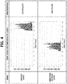
- FIG. 4 is a view showing analysis of an opaque logo as the opaque fixed image and a semitransparent logo as the semitransparent fixed image.
- gray scales of logo are distributed only in a high gray scale portion whereas after displaying 100 frames of a semitransparent logo in a region, gray scales of logo are distributed in only an intermediate gray scale portion.
- a luminance correction for an opaque fixed image region can be performed to prevent or reduce the ghost image effect.
- FIG. 5 is a conceptual diagram illustrating an RGB-to-WRGB data conversion for an opaque fixed image region according to one embodiment of the present invention.
- RGB data indicating white in an opaque fixed image are converted into WRGB data
- WGB data or WRB data may be adjusted without using R or G data to reduce luminance.
- input linear R(255), G(255), and B(255) data of an opaque fixed image shown in FIG. 5 may be converted into W(220), R(0), G(30), and B(140) data of an opaque fixed image of the related art to reduce luminance.
- luminous efficacy of the WRGB sub-pixels sequentially dccrcascs in the order of W, G, R and B.
- the B sub-pixels may be driven with 30 times more energy than the W sub-pixels.
- a use rate of the B sub-pixels in the fixed image (logo) region is decreased, and instead, the use rate of any one of WRG is increased to restrain deterioration of the B sub-pixels having low efficacy as shown in the right side of FIG. 5 .
- Such modification results in the same level of luminance as the related art (the left side of FIG. 5 ).
- the use rate of a sub-pixel as described herein refers to current through the sub-pixel during a predetermined amount of time. For example, as shown in FIG.
- a use rate of the B sub-pixels of the embodiment may be reduced by 30 % while increasing a use rate of the W sub-pixels may be increased by only 1 % to reduce deterioration of the B sub-pixels and maintain the same level of luminance.
- it is possible to reduce deterioration of the B sub-pixels and thus reduce or prevent a ghost image issue due to the fixed image by adjusting data representing the use rate of B sub-pixels to reduce the use rate of B sub-pixels by 30 %, and adjusting data representing the use rate of W sub-pixels to increase the use of B sub-pixels by only 1 %.
- Such adjustment considerably increases the lifespan of the B sub-pixels.
- FIG. 6 is a graph showing the characteristics of a color difference ⁇ u'v' of a just noticeable difference (JND) and a just acceptable difference (JAD) of a ghost image of a yellow logo based on the luminance of a background of the OLED display device applied to an embodiment of the present invention
- u' and v' herein refer to chromacity coordinates in a color space.
- y axis indicates persons' noticing or accepting color difference at 50% response rate (i.e., 50% of people notices color difference).
- the 50% JND at the luminance of 80 cd/m 2 is derived as 0.002.
- a JAD graph indicating persons accepting color difference at 50% response rate i.e., 50% of people indicating that the color difference is acceptable
- the 50% JAD at the luminance of 80 cd/m 2 is derived as 0.011.
- the luminance of the logo region is corrected based on the color difference ⁇ u'v' of the allowance limit (JAD) of the afterimage of the yellow logo, which is 0.011 (at luminance of 80 cd/m 2 ), thereby preventing recognition of change in color due to deterioration of the logo region. It is possible to set a criterion of deterioration correction for the fixed image region based on the luminance efficacies of the WRGB sub-pixels described with reference to FIG. 5 and the recognition test result described with reference to FIG. 6 .
- the driving quantity of the B sub-pixels, which have low luminous efficacy is decreased, and the reduction in luminance as the result thereof is supplemented by increasing the driving amount of the W sub-pixels, which have high luminous efficacy.
- the total luminance of the WRGB sub-pixels is adjusted to maintain a level within JAD be (0.011) of the color difference ⁇ u'v' with the original fixed image, i.e. the deterioration recognition allowance limit.
- the use rate of the sub-pixels per color may be adjusted by applying different weights (gain) to data per color.
- weights gain
- One of the weights per color e.g. a B weight
- a weight equivalent to 1/30 of the decrement of the B weight may be added to a W weight to correct luminance.
- the weights per color are set based on the luminance correction and deterioration recognition allowance limit.
- B luminance Y(B) is decreased by the weight ⁇ which is less than 1, and 1/30 of its decrement is added to the W weight ⁇ .
- the weight ( ⁇ , ⁇ ) may be preset by designers of the display device, and may be stored in a memory of image processing circuit 50.
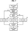
- FIG. 7 is a flowchart showing illustrating an image processing method according to an embodiment of the present invention.
- FIG. 8 is a schematic block diagram illustrating components of the image processing circuit 50 according to an embodiment of the present invention. The image processing method of FIG. 7 is performed by the image processing circuit shown in FIG. 8 . Consequently, the following description will be made with reference to both FIGs. 7 and 8 .
- the image processing circuit 50 may include, among other components, a processor 82 and a memory (non-transitory computer readable storage medium) 84.
- the memory 84 may store modules including, an image input unit 2, a fixed image region detection unit 4, a fixed image determination unit 6, first to third data conversion units 8, 10, and 12, an image synthesis unit 14, and an image output unit 16.
- the image input unit 2 and the image output unit 16 may be omitted.
- the processor 82 executes instructions stored in the memory 84 to perform operations as described herein.
- the fixed image region detection unit 4 receives S2 RGB data as an input image through the image input unit 2.
- the fixed image region detection unit 4 analyzes the received RGB data to determine whether a fixed image region is present in the input image.
- the fixed image region detection unit 4 After determining S4 that the fixed image region is present in the input image, the fixed image region detection unit 4 outputs RGB data of the fixed image region to the fixed image determination unit 6. When the fixed image region is present in the input image, the fixed image region detection unit 4 outputs RGB data of a general region to the second data conversion unit 10 and the image data of the fixed image region to the fixed image determination unit 6. In other words, the fixed image region detection unit 4 divides the received RGB data into RGB data of a fixed image region and RGB data of a general region, outputs the RGB data of the fixed image region to the fixed image determination unit 6, and outputs the RGB data of the general region to the second data conversion unit 10. When no fixed image region is detected all RGB data is provided to the second data conversion unit 10.
- the fixed image region detection unit 4 may compare RGB data between adjacent frames during a plurality of frames and identify a region having identical or similar data across the plurality of frames.
- coordinate information for a fixed image region may be received from a source external to the image processing circuit 50, and the fixed image region detection unit may locate a fixed image region corresponding to the coordinate information provided from the source.
- Various other known technologies for detecting a fixed image region or a logo region may be applied.
- the fixed image region detection unit 4 outputs the RGB data belonging to the detected fixed image region to the fixed image determination unit 6, and outputs the RGB data that do not belong to the fixed image region (i.e., the RGB data belonging to the general region) to the second data conversion unit 10.
- the fixed image determination unit 6 determines S6 whether a fixed image is opaque or semitransparent using the RGB data of the fixed image region received from the fixed image region detection unit 4. When it is determined that the fixed image is opaque, the fixed image determination unit 6 outputs the RGB data to the first data conversion unit 8. When it is determined that the fixed image is semitransparent, the fixed image determination unit 6 outputs the RGB data to the third data conversion unit 12.
- One way of determining whether the fixed image is opaque or semitransparent is by using a gray scale value obtained by accumulating and averaging across a fixed image received from the fixed image region detection unit 4 during a plurality of frames. If the gray scale value is of a specific value or more (e.g., 200 or more in 8 bit grayscale), the fixed image determination unit 6 determines that the fixed image is opaque, and outputs the RGB data to the first data conversion unit 8. When the gray scale value is less than the specific value, the fixed image determination unit 6 determines that the fixed image is transparent or semitransparent, and outputs the RGB data to the third data conversion unit 12.
- a specific value or more e.g. 200 or more in 8 bit grayscale
- the first data conversion unit 8 applies a luminous efficacy preset per color to the RGB data of the opaque fixed image region received from the fixed image determination unit 6 based on different luminous efficacies of each color and a cognitive ghost image allowance limit to correct the luminance of the fixed image and to convert S8 the RGB data into W'R'G'B' data.
- the total luminance of WRGB data may be adjusted so that the total luminance of WRGB data is lower than the total luminance of the original RGB data over time.
- a B weight ⁇ set to be less than 1 may be applied to reduce B data, and a W weight ⁇ (equivalent to addition of 1/30 of the decrement of the B weight) may be applied to W data to correct luminance.
- the third data conversion unit 12 converts S10 the RGB data of the semitransparent fixed image region received from the fixed image determination unit 6 into WRGB data using a general RGB-to-WRGB data conversion method that is well known in the art.
- the second data conversion unit 10 converts S12 the RGB data of the general region received from the fixed image region detection unit 4 into WRGB data using a general RGB-to-WRGB data conversion method that is well known in the art.
- the first to third data conversion units 8, 10, and 12 may also perform de-gamma processing for inverse gamma into linear luminance data per color, adjustment of luminance per each color, and gamma processing into WRGB data.
- the image synthesis unit 14 synthesizes S14 the W'R'G'B' data of the fixed image region from the first data conversion unit 8 or the WRGB data of the fixed image region from the third data conversion unit 12 and the WRGB data of the general region from the second data conversion unit 10, and outputs S16 the synthesized WRGB data to the data driver 200 through the image output unit 16.
- the image synthesis unit 14 may synthesize the W'R'G'B' data or the WRGB data of the fixed image region and the WRGB data of the general region to generate and output a corrected image that is capable of minimizing abrupt reduction of B data in the fixed image region.
- the OLED display device may be applied to various kinds of electronic devices, such as a video camera, a digital camera, a head mount display (goggle type display), a car navigation system, a projector, a car stereo, a personal computer, a portable information terminal (a mobile computer, a mobile phone, or an electronic book reader), and a TV set.
- electronic devices such as a video camera, a digital camera, a head mount display (goggle type display), a car navigation system, a projector, a car stereo, a personal computer, a portable information terminal (a mobile computer, a mobile phone, or an electronic book reader), and a TV set.
- the image processing method and circuit of the embodiments increase or decrease color components based on luminous efficacies for each color component and the likelihood of causing ghost images to modulate data of a fixed image region, thereby reducing deterioration and color distortion of the fixed image region and extending the lifespan of a display device.
- the image processing method and circuit according to the present invention and the OLED display device using the same discriminatively apply a weight per color in consideration of different luminous efficacies per color and a cognitive afterimage allowance limit to modulate data of a fixed image region, thereby reducing deterioration and color distortion of the fixed image region and extending a lifespan.
Applications Claiming Priority (1)
| Application Number | Priority Date | Filing Date | Title |
|---|---|---|---|
| KR1020150074987A KR102207190B1 (ko) | 2015-05-28 | 2015-05-28 | 영상 처리 방법 및 영상 처리 회로와, 그를 이용한 표시 장치 |
Publications (2)
| Publication Number | Publication Date |
|---|---|
| EP3098803A1 EP3098803A1 (en) | 2016-11-30 |
| EP3098803B1 true EP3098803B1 (en) | 2021-07-28 |
Family
ID=55070706
Family Applications (1)
| Application Number | Title | Priority Date | Filing Date |
|---|---|---|---|
| EP15200740.7A Active EP3098803B1 (en) | 2015-05-28 | 2015-12-17 | Image processing method, image processing circuit, and organic light emitting diode display device using the same |
Country Status (4)
| Country | Link |
|---|---|
| US (1) | US10157568B2 (ko) |
| EP (1) | EP3098803B1 (ko) |
| KR (1) | KR102207190B1 (ko) |
| CN (1) | CN106205485B (ko) |
Families Citing this family (14)
| Publication number | Priority date | Publication date | Assignee | Title |
|---|---|---|---|---|
| KR102391476B1 (ko) * | 2015-12-02 | 2022-04-28 | 삼성디스플레이 주식회사 | 표시 장치 및 그 구동 방법 |
| EP3413294B1 (en) * | 2017-06-08 | 2020-07-29 | Vestel Elektronik Sanayi ve Ticaret A.S. | Method, controller and display device of rgb image content |
| KR102370442B1 (ko) * | 2017-08-17 | 2022-03-03 | 엘지전자 주식회사 | 영상표시장치 |
| US11315521B2 (en) * | 2017-09-21 | 2022-04-26 | Samsung Electronics Co., Ltd. | Electronic device and method for brightness control of electronic device |
| CN108038815B (zh) * | 2017-12-20 | 2019-12-17 | 深圳云天励飞技术有限公司 | 集成电路 |
| CN111527540B (zh) * | 2018-03-27 | 2021-10-01 | 华为技术有限公司 | 一种基色转化方法及电子设备 |
| CN110321907B (zh) * | 2018-03-28 | 2021-08-17 | 京东方科技集团股份有限公司 | 一种数据处理顺序的确定方法、显示装置及其显示方法 |
| KR102552965B1 (ko) * | 2018-06-27 | 2023-07-10 | 엘지디스플레이 주식회사 | 모니터용 유기 발광 다이오드 디스플레이 장치 및 그의 영상 처리 방법 |
| JP7206968B2 (ja) * | 2019-02-01 | 2023-01-18 | トヨタ自動車株式会社 | サーバ及び交通管理システム |
| JP7038684B2 (ja) * | 2019-08-01 | 2022-03-18 | Tvs Regza株式会社 | 画像表示装置および画像処理方法 |
| KR20210148474A (ko) * | 2020-05-28 | 2021-12-08 | 삼성디스플레이 주식회사 | 표시 장치 및 그 구동 방법 |
| CN111679804B (zh) * | 2020-06-02 | 2023-05-02 | 深圳创维-Rgb电子有限公司 | 一种oled显示补偿方法、系统、显示设备及存储介质 |
| KR20220095463A (ko) * | 2020-12-30 | 2022-07-07 | 엘지디스플레이 주식회사 | 디스플레이 장치 및 디스플레이 패널 |
| US20220230575A1 (en) * | 2021-01-19 | 2022-07-21 | Dell Products L.P. | Transforming background color of displayed documents to increase lifetime of oled display |
Citations (1)
| Publication number | Priority date | Publication date | Assignee | Title |
|---|---|---|---|---|
| US20040178743A1 (en) * | 2002-12-16 | 2004-09-16 | Eastman Kodak Company | Color OLED display system having improved performance |
Family Cites Families (9)
| Publication number | Priority date | Publication date | Assignee | Title |
|---|---|---|---|---|
| JP4679242B2 (ja) * | 2005-05-25 | 2011-04-27 | 三洋電機株式会社 | 表示装置 |
| US20070109284A1 (en) * | 2005-08-12 | 2007-05-17 | Semiconductor Energy Laboratory Co., Ltd. | Display device |
| US7791621B2 (en) | 2006-04-18 | 2010-09-07 | Toppoly Optoelectronics Corp. | Systems and methods for providing driving voltages to RGBW display panels |
| JP5430068B2 (ja) | 2008-02-15 | 2014-02-26 | 株式会社ジャパンディスプレイ | 表示装置 |
| US8896641B2 (en) | 2011-06-01 | 2014-11-25 | Lg Display Co., Ltd. | Organic light emitting diode display device and method of driving the same |
| KR101857627B1 (ko) * | 2011-08-31 | 2018-06-28 | 엘지디스플레이 주식회사 | 유기전계발광표시장치와 이의 구동방법 |
| CN103456280A (zh) | 2012-06-01 | 2013-12-18 | 北京凡达讯科技有限公司 | 显示rgb彩色图像的方法 |
| KR102090705B1 (ko) * | 2012-09-07 | 2020-03-19 | 삼성디스플레이 주식회사 | 표시 장치 및 표시 장치의 구동 방법 |
| KR101957974B1 (ko) | 2012-11-30 | 2019-03-14 | 엘지디스플레이 주식회사 | 유기발광다이오드 표시장치와 그 구동방법 |
-
2015
- 2015-05-28 KR KR1020150074987A patent/KR102207190B1/ko active IP Right Grant
- 2015-12-02 US US14/957,541 patent/US10157568B2/en active Active
- 2015-12-16 CN CN201510944731.6A patent/CN106205485B/zh active Active
- 2015-12-17 EP EP15200740.7A patent/EP3098803B1/en active Active
Patent Citations (1)
| Publication number | Priority date | Publication date | Assignee | Title |
|---|---|---|---|---|
| US20040178743A1 (en) * | 2002-12-16 | 2004-09-16 | Eastman Kodak Company | Color OLED display system having improved performance |
Also Published As
| Publication number | Publication date |
|---|---|
| CN106205485B (zh) | 2018-11-30 |
| CN106205485A (zh) | 2016-12-07 |
| EP3098803A1 (en) | 2016-11-30 |
| KR102207190B1 (ko) | 2021-01-25 |
| US20160351115A1 (en) | 2016-12-01 |
| KR20160139678A (ko) | 2016-12-07 |
| US10157568B2 (en) | 2018-12-18 |
Similar Documents
| Publication | Publication Date | Title |
|---|---|---|
| EP3098803B1 (en) | Image processing method, image processing circuit, and organic light emitting diode display device using the same | |
| CN108009993B (zh) | 处理高动态范围图像的方法和模块以及使用其的显示设备 | |
| KR101492712B1 (ko) | 유기발광다이오드 표시장치와 그 구동방법 | |
| KR102370367B1 (ko) | 표시 장치 및 이의 구동 방법 | |
| US20070126758A1 (en) | Flat display panel, picture quality controlling apparatus and method thereof | |
| US11244633B2 (en) | Method of driving display panel by compensating for flicker and display apparatus thereof | |
| EP3223266B1 (en) | Organic light emitting diode display device and method of operating the same | |
| KR20140070792A (ko) | 타이밍 컨트롤러 및 그 구동 방법과 이를 이용한 표시장치 | |
| KR20170011674A (ko) | 영상 처리 방법, 영상 처리 회로와, 그를 이용한 표시 장치 | |
| KR102510573B1 (ko) | 투명 표시 장치 및 그 구동 방법 | |
| KR102315691B1 (ko) | 유기발광다이오드표시장치 및 이의 구동방법 | |
| KR20160035192A (ko) | 표시장치와 그 휘도 향상 방법 | |
| KR102037517B1 (ko) | 유기발광다이오드 표시장치와 그 구동방법 | |
| WO2021131830A1 (ja) | 信号処理装置、信号処理方法、及び表示装置 | |
| US20230410733A1 (en) | Signal Processing Apparatus, Signal Processing Method, And Display Apparatus | |
| US20110254850A1 (en) | Image processing apparatus, display system, electronic apparatus and method of processing image | |
| KR101964457B1 (ko) | 유기발광다이오드 표시장치와 그 구동방법 | |
| KR102597751B1 (ko) | 멀티비젼 시스템 및 그 구동 방법 | |
| KR20170135569A (ko) | 하이 다이나믹 레인지를 위한 4색 표시 장치 | |
| KR20170073771A (ko) | 유기발광표시패널, 유기발광표시장치 및 유기발광표시장치의 구동 방법 | |
| KR20160092335A (ko) | 영상 처리 방법 및 장치와 이를 이용하는 표시 장치 | |
| KR20160046983A (ko) | 소비 전력 제어 방법 및 장치와 이를 이용한 표시장치 | |
| CN114677962A (zh) | 用于防止劣化的显示装置及其补偿方法 | |
| KR101936679B1 (ko) | 유기발광표시장치 및 그 구동방법 | |
| KR102006264B1 (ko) | 유기발광다이오드 표시장치와 그 구동방법 |
Legal Events
| Date | Code | Title | Description |
|---|---|---|---|
| PUAI | Public reference made under article 153(3) epc to a published international application that has entered the european phase |
Free format text: ORIGINAL CODE: 0009012 |
|
| 17P | Request for examination filed |
Effective date: 20151217 |
|
| AK | Designated contracting states |
Kind code of ref document: A1 Designated state(s): AL AT BE BG CH CY CZ DE DK EE ES FI FR GB GR HR HU IE IS IT LI LT LU LV MC MK MT NL NO PL PT RO RS SE SI SK SM TR |
|
| AX | Request for extension of the european patent |
Extension state: BA ME |
|
| RBV | Designated contracting states (corrected) |
Designated state(s): AL AT BE BG CH CY CZ DE DK EE ES FI FR GB GR HR HU IE IS IT LI LT LU LV MC MK MT NL NO PL PT RO RS SE SI SK SM TR |
|
| STAA | Information on the status of an ep patent application or granted ep patent |
Free format text: STATUS: EXAMINATION IS IN PROGRESS |
|
| 17Q | First examination report despatched |
Effective date: 20200610 |
|
| STAA | Information on the status of an ep patent application or granted ep patent |
Free format text: STATUS: EXAMINATION IS IN PROGRESS |
|
| GRAP | Despatch of communication of intention to grant a patent |
Free format text: ORIGINAL CODE: EPIDOSNIGR1 |
|
| STAA | Information on the status of an ep patent application or granted ep patent |
Free format text: STATUS: GRANT OF PATENT IS INTENDED |
|
| INTG | Intention to grant announced |
Effective date: 20210301 |
|
| GRAS | Grant fee paid |
Free format text: ORIGINAL CODE: EPIDOSNIGR3 |
|
| GRAA | (expected) grant |
Free format text: ORIGINAL CODE: 0009210 |
|
| STAA | Information on the status of an ep patent application or granted ep patent |
Free format text: STATUS: THE PATENT HAS BEEN GRANTED |
|
| AK | Designated contracting states |
Kind code of ref document: B1 Designated state(s): AL AT BE BG CH CY CZ DE DK EE ES FI FR GB GR HR HU IE IS IT LI LT LU LV MC MK MT NL NO PL PT RO RS SE SI SK SM TR |
|
| REG | Reference to a national code |
Ref country code: GB Ref legal event code: FG4D |
|
| REG | Reference to a national code |
Ref country code: CH Ref legal event code: EP |
|
| REG | Reference to a national code |
Ref country code: DE Ref legal event code: R096 Ref document number: 602015071653 Country of ref document: DE |
|
| REG | Reference to a national code |
Ref country code: AT Ref legal event code: REF Ref document number: 1415413 Country of ref document: AT Kind code of ref document: T Effective date: 20210815 |
|
| REG | Reference to a national code |
Ref country code: IE Ref legal event code: FG4D |
|
| REG | Reference to a national code |
Ref country code: LT Ref legal event code: MG9D |
|
| REG | Reference to a national code |
Ref country code: NL Ref legal event code: MP Effective date: 20210728 |
|
| REG | Reference to a national code |
Ref country code: AT Ref legal event code: MK05 Ref document number: 1415413 Country of ref document: AT Kind code of ref document: T Effective date: 20210728 |
|
| PG25 | Lapsed in a contracting state [announced via postgrant information from national office to epo] |
Ref country code: LT Free format text: LAPSE BECAUSE OF FAILURE TO SUBMIT A TRANSLATION OF THE DESCRIPTION OR TO PAY THE FEE WITHIN THE PRESCRIBED TIME-LIMIT Effective date: 20210728 Ref country code: AT Free format text: LAPSE BECAUSE OF FAILURE TO SUBMIT A TRANSLATION OF THE DESCRIPTION OR TO PAY THE FEE WITHIN THE PRESCRIBED TIME-LIMIT Effective date: 20210728 Ref country code: BG Free format text: LAPSE BECAUSE OF FAILURE TO SUBMIT A TRANSLATION OF THE DESCRIPTION OR TO PAY THE FEE WITHIN THE PRESCRIBED TIME-LIMIT Effective date: 20211028 Ref country code: ES Free format text: LAPSE BECAUSE OF FAILURE TO SUBMIT A TRANSLATION OF THE DESCRIPTION OR TO PAY THE FEE WITHIN THE PRESCRIBED TIME-LIMIT Effective date: 20210728 Ref country code: FI Free format text: LAPSE BECAUSE OF FAILURE TO SUBMIT A TRANSLATION OF THE DESCRIPTION OR TO PAY THE FEE WITHIN THE PRESCRIBED TIME-LIMIT Effective date: 20210728 Ref country code: NL Free format text: LAPSE BECAUSE OF FAILURE TO SUBMIT A TRANSLATION OF THE DESCRIPTION OR TO PAY THE FEE WITHIN THE PRESCRIBED TIME-LIMIT Effective date: 20210728 Ref country code: NO Free format text: LAPSE BECAUSE OF FAILURE TO SUBMIT A TRANSLATION OF THE DESCRIPTION OR TO PAY THE FEE WITHIN THE PRESCRIBED TIME-LIMIT Effective date: 20211028 Ref country code: PT Free format text: LAPSE BECAUSE OF FAILURE TO SUBMIT A TRANSLATION OF THE DESCRIPTION OR TO PAY THE FEE WITHIN THE PRESCRIBED TIME-LIMIT Effective date: 20211129 Ref country code: HR Free format text: LAPSE BECAUSE OF FAILURE TO SUBMIT A TRANSLATION OF THE DESCRIPTION OR TO PAY THE FEE WITHIN THE PRESCRIBED TIME-LIMIT Effective date: 20210728 Ref country code: SE Free format text: LAPSE BECAUSE OF FAILURE TO SUBMIT A TRANSLATION OF THE DESCRIPTION OR TO PAY THE FEE WITHIN THE PRESCRIBED TIME-LIMIT Effective date: 20210728 Ref country code: RS Free format text: LAPSE BECAUSE OF FAILURE TO SUBMIT A TRANSLATION OF THE DESCRIPTION OR TO PAY THE FEE WITHIN THE PRESCRIBED TIME-LIMIT Effective date: 20210728 |
|
| PG25 | Lapsed in a contracting state [announced via postgrant information from national office to epo] |
Ref country code: PL Free format text: LAPSE BECAUSE OF FAILURE TO SUBMIT A TRANSLATION OF THE DESCRIPTION OR TO PAY THE FEE WITHIN THE PRESCRIBED TIME-LIMIT Effective date: 20210728 Ref country code: LV Free format text: LAPSE BECAUSE OF FAILURE TO SUBMIT A TRANSLATION OF THE DESCRIPTION OR TO PAY THE FEE WITHIN THE PRESCRIBED TIME-LIMIT Effective date: 20210728 Ref country code: GR Free format text: LAPSE BECAUSE OF FAILURE TO SUBMIT A TRANSLATION OF THE DESCRIPTION OR TO PAY THE FEE WITHIN THE PRESCRIBED TIME-LIMIT Effective date: 20211029 |
|
| PG25 | Lapsed in a contracting state [announced via postgrant information from national office to epo] |
Ref country code: DK Free format text: LAPSE BECAUSE OF FAILURE TO SUBMIT A TRANSLATION OF THE DESCRIPTION OR TO PAY THE FEE WITHIN THE PRESCRIBED TIME-LIMIT Effective date: 20210728 |
|
| REG | Reference to a national code |
Ref country code: DE Ref legal event code: R097 Ref document number: 602015071653 Country of ref document: DE |
|
| PG25 | Lapsed in a contracting state [announced via postgrant information from national office to epo] |
Ref country code: SM Free format text: LAPSE BECAUSE OF FAILURE TO SUBMIT A TRANSLATION OF THE DESCRIPTION OR TO PAY THE FEE WITHIN THE PRESCRIBED TIME-LIMIT Effective date: 20210728 Ref country code: SK Free format text: LAPSE BECAUSE OF FAILURE TO SUBMIT A TRANSLATION OF THE DESCRIPTION OR TO PAY THE FEE WITHIN THE PRESCRIBED TIME-LIMIT Effective date: 20210728 Ref country code: RO Free format text: LAPSE BECAUSE OF FAILURE TO SUBMIT A TRANSLATION OF THE DESCRIPTION OR TO PAY THE FEE WITHIN THE PRESCRIBED TIME-LIMIT Effective date: 20210728 Ref country code: EE Free format text: LAPSE BECAUSE OF FAILURE TO SUBMIT A TRANSLATION OF THE DESCRIPTION OR TO PAY THE FEE WITHIN THE PRESCRIBED TIME-LIMIT Effective date: 20210728 Ref country code: CZ Free format text: LAPSE BECAUSE OF FAILURE TO SUBMIT A TRANSLATION OF THE DESCRIPTION OR TO PAY THE FEE WITHIN THE PRESCRIBED TIME-LIMIT Effective date: 20210728 Ref country code: AL Free format text: LAPSE BECAUSE OF FAILURE TO SUBMIT A TRANSLATION OF THE DESCRIPTION OR TO PAY THE FEE WITHIN THE PRESCRIBED TIME-LIMIT Effective date: 20210728 |
|
| PLBE | No opposition filed within time limit |
Free format text: ORIGINAL CODE: 0009261 |
|
| STAA | Information on the status of an ep patent application or granted ep patent |
Free format text: STATUS: NO OPPOSITION FILED WITHIN TIME LIMIT |
|
| 26N | No opposition filed |
Effective date: 20220429 |
|
| PG25 | Lapsed in a contracting state [announced via postgrant information from national office to epo] |
Ref country code: MC Free format text: LAPSE BECAUSE OF FAILURE TO SUBMIT A TRANSLATION OF THE DESCRIPTION OR TO PAY THE FEE WITHIN THE PRESCRIBED TIME-LIMIT Effective date: 20210728 Ref country code: IT Free format text: LAPSE BECAUSE OF FAILURE TO SUBMIT A TRANSLATION OF THE DESCRIPTION OR TO PAY THE FEE WITHIN THE PRESCRIBED TIME-LIMIT Effective date: 20210728 |
|
| REG | Reference to a national code |
Ref country code: CH Ref legal event code: PL |
|
| REG | Reference to a national code |
Ref country code: BE Ref legal event code: MM Effective date: 20211231 |
|
| PG25 | Lapsed in a contracting state [announced via postgrant information from national office to epo] |
Ref country code: LU Free format text: LAPSE BECAUSE OF NON-PAYMENT OF DUE FEES Effective date: 20211217 Ref country code: IE Free format text: LAPSE BECAUSE OF NON-PAYMENT OF DUE FEES Effective date: 20211217 |
|
| PG25 | Lapsed in a contracting state [announced via postgrant information from national office to epo] |
Ref country code: BE Free format text: LAPSE BECAUSE OF NON-PAYMENT OF DUE FEES Effective date: 20211231 |
|
| PG25 | Lapsed in a contracting state [announced via postgrant information from national office to epo] |
Ref country code: LI Free format text: LAPSE BECAUSE OF NON-PAYMENT OF DUE FEES Effective date: 20211231 Ref country code: CH Free format text: LAPSE BECAUSE OF NON-PAYMENT OF DUE FEES Effective date: 20211231 |
|
| PG25 | Lapsed in a contracting state [announced via postgrant information from national office to epo] |
Ref country code: HU Free format text: LAPSE BECAUSE OF FAILURE TO SUBMIT A TRANSLATION OF THE DESCRIPTION OR TO PAY THE FEE WITHIN THE PRESCRIBED TIME-LIMIT; INVALID AB INITIO Effective date: 20151217 |
|
| PG25 | Lapsed in a contracting state [announced via postgrant information from national office to epo] |
Ref country code: CY Free format text: LAPSE BECAUSE OF FAILURE TO SUBMIT A TRANSLATION OF THE DESCRIPTION OR TO PAY THE FEE WITHIN THE PRESCRIBED TIME-LIMIT Effective date: 20210728 |
|
| PGFP | Annual fee paid to national office [announced via postgrant information from national office to epo] |
Ref country code: GB Payment date: 20231023 Year of fee payment: 9 |
|
| REG | Reference to a national code |
Ref country code: DE Ref legal event code: R082 Ref document number: 602015071653 Country of ref document: DE Representative=s name: TER MEER STEINMEISTER & PARTNER PATENTANWAELTE, DE |
|
| PGFP | Annual fee paid to national office [announced via postgrant information from national office to epo] |
Ref country code: FR Payment date: 20231024 Year of fee payment: 9 Ref country code: DE Payment date: 20231023 Year of fee payment: 9 |