EP3098681B1 - Gestion de la santé d'intelligence artificielle de système hôte - Google Patents
Gestion de la santé d'intelligence artificielle de système hôte Download PDFInfo
- Publication number
- EP3098681B1 EP3098681B1 EP16160362.6A EP16160362A EP3098681B1 EP 3098681 B1 EP3098681 B1 EP 3098681B1 EP 16160362 A EP16160362 A EP 16160362A EP 3098681 B1 EP3098681 B1 EP 3098681B1
- Authority
- EP
- European Patent Office
- Prior art keywords
- subsystems
- host system
- parameters
- health management
- neural network
- Prior art date
- Legal status (The legal status is an assumption and is not a legal conclusion. Google has not performed a legal analysis and makes no representation as to the accuracy of the status listed.)
- Active
Links
- 230000036541 health Effects 0.000 title claims description 73
- 238000013473 artificial intelligence Methods 0.000 title description 20
- 230000004044 response Effects 0.000 claims description 54
- 238000013528 artificial neural network Methods 0.000 claims description 38
- 230000002159 abnormal effect Effects 0.000 claims description 35
- 238000000034 method Methods 0.000 claims description 33
- 238000012549 training Methods 0.000 claims description 24
- 239000013598 vector Substances 0.000 claims description 18
- 238000012544 monitoring process Methods 0.000 claims description 14
- 238000003062 neural network model Methods 0.000 claims description 7
- 238000004393 prognosis Methods 0.000 claims description 4
- 238000004590 computer program Methods 0.000 claims description 3
- 238000003745 diagnosis Methods 0.000 claims description 3
- 230000001747 exhibiting effect Effects 0.000 claims 3
- 238000007781 pre-processing Methods 0.000 claims 1
- 230000006870 function Effects 0.000 description 10
- 238000001514 detection method Methods 0.000 description 8
- 238000001228 spectrum Methods 0.000 description 7
- 238000004088 simulation Methods 0.000 description 6
- 238000010586 diagram Methods 0.000 description 5
- 238000000605 extraction Methods 0.000 description 5
- 238000013459 approach Methods 0.000 description 4
- 238000004422 calculation algorithm Methods 0.000 description 4
- 238000005259 measurement Methods 0.000 description 4
- 230000008569 process Effects 0.000 description 4
- 238000012545 processing Methods 0.000 description 4
- 230000005856 abnormality Effects 0.000 description 3
- 238000004458 analytical method Methods 0.000 description 3
- 238000004891 communication Methods 0.000 description 3
- 230000007257 malfunction Effects 0.000 description 3
- 230000008439 repair process Effects 0.000 description 3
- 238000005516 engineering process Methods 0.000 description 2
- 230000003862 health status Effects 0.000 description 2
- 239000011159 matrix material Substances 0.000 description 2
- 241000196324 Embryophyta Species 0.000 description 1
- 235000011034 Rubus glaucus Nutrition 0.000 description 1
- 244000235659 Rubus idaeus Species 0.000 description 1
- 235000009122 Rubus idaeus Nutrition 0.000 description 1
- 238000003491 array Methods 0.000 description 1
- 230000006399 behavior Effects 0.000 description 1
- 229910002056 binary alloy Inorganic materials 0.000 description 1
- 230000000295 complement effect Effects 0.000 description 1
- 238000013016 damping Methods 0.000 description 1
- 238000012517 data analytics Methods 0.000 description 1
- 238000013461 design Methods 0.000 description 1
- 230000000694 effects Effects 0.000 description 1
- 239000012530 fluid Substances 0.000 description 1
- 230000007366 host health Effects 0.000 description 1
- 230000002452 interceptive effect Effects 0.000 description 1
- 238000012423 maintenance Methods 0.000 description 1
- 230000007246 mechanism Effects 0.000 description 1
- 230000003287 optical effect Effects 0.000 description 1
- 238000003909 pattern recognition Methods 0.000 description 1
- 230000001953 sensory effect Effects 0.000 description 1
- 238000010183 spectrum analysis Methods 0.000 description 1
- 208000024891 symptom Diseases 0.000 description 1
- 230000000007 visual effect Effects 0.000 description 1
Images


Classifications
-
- G—PHYSICS
- G06—COMPUTING; CALCULATING OR COUNTING
- G06F—ELECTRIC DIGITAL DATA PROCESSING
- G06F11/00—Error detection; Error correction; Monitoring
- G06F11/22—Detection or location of defective computer hardware by testing during standby operation or during idle time, e.g. start-up testing
- G06F11/2257—Detection or location of defective computer hardware by testing during standby operation or during idle time, e.g. start-up testing using expert systems
-
- G—PHYSICS
- G05—CONTROLLING; REGULATING
- G05B—CONTROL OR REGULATING SYSTEMS IN GENERAL; FUNCTIONAL ELEMENTS OF SUCH SYSTEMS; MONITORING OR TESTING ARRANGEMENTS FOR SUCH SYSTEMS OR ELEMENTS
- G05B23/00—Testing or monitoring of control systems or parts thereof
- G05B23/02—Electric testing or monitoring
- G05B23/0205—Electric testing or monitoring by means of a monitoring system capable of detecting and responding to faults
- G05B23/0218—Electric testing or monitoring by means of a monitoring system capable of detecting and responding to faults characterised by the fault detection method dealing with either existing or incipient faults
- G05B23/0243—Electric testing or monitoring by means of a monitoring system capable of detecting and responding to faults characterised by the fault detection method dealing with either existing or incipient faults model based detection method, e.g. first-principles knowledge model
- G05B23/0254—Electric testing or monitoring by means of a monitoring system capable of detecting and responding to faults characterised by the fault detection method dealing with either existing or incipient faults model based detection method, e.g. first-principles knowledge model based on a quantitative model, e.g. mathematical relationships between inputs and outputs; functions: observer, Kalman filter, residual calculation, Neural Networks
-
- G—PHYSICS
- G06—COMPUTING; CALCULATING OR COUNTING
- G06N—COMPUTING ARRANGEMENTS BASED ON SPECIFIC COMPUTATIONAL MODELS
- G06N20/00—Machine learning
-
- G—PHYSICS
- G06—COMPUTING; CALCULATING OR COUNTING
- G06N—COMPUTING ARRANGEMENTS BASED ON SPECIFIC COMPUTATIONAL MODELS
- G06N3/00—Computing arrangements based on biological models
- G06N3/02—Neural networks
- G06N3/08—Learning methods
- G06N3/088—Non-supervised learning, e.g. competitive learning
Definitions
- the embodiments herein generally relate to health management, and, more particularly, to a method and system for artificial intelligence (AI) based diagnostic and prognostic health management of host systems.
- AI artificial intelligence
- multi-domain 'mechatronics' systems are being developed that operates in a closed-loop/close-interaction.
- Examples of such system include vehicle systems, aircraft systems, automotive systems, turbine engines, and so on. Since the systems being developed these days are complex, the health management of such systems pose challenges, as failure of any critical system component can trigger catastrophic system failures. Hence, health management of such multi-domain complex systems is of vital importance.
- a method for recognition of normal and abnormal conditions can be performed with at least one neural network is disclosed.
- trend data of an object system before a recognition-step, are entered as input data to an input layer of each neural network and data of this system at the recognition-step are entered as objective output data to an output layer of the neural network.
- multiple sets of trend data showing at least one normal condition of this system are formed in the neural network in order to obtained learned weights and biases.
- a fault detection system provides the ability to detect symptoms of fault in turbine engines and other mechanical systems that have nonlinear relationships between two or more variables, is disclosed.
- the fault detection system uses a neural network to perform feature extraction from data for representation of faulty or normal conditions.
- the values of extracted features, referred to herein as scores, are then used to determine the likelihood of fault in the system.
- the lower order scores can be classified into one or more clusters, where some clusters represent types of faults in the turbine engine.
- another particular prior art US 6138109 A discloses a malfunction diagnostic and repair guidance system and method wherein a matrix of numbers indicating the state of a complex binary system is used as an input vector for a neural network pattern processing capability that is focused to distinguish malfunction types of patterns.
- the neural network capability provides two complementary network types to classify and generalize the binary matrix.
- An interactive operator interface is updated with each repair after the root cause and is proposed repair of a malfunction is identified.
- a particular prior art US 2013/0030765 A1 discloses a system for monitoring a machine, which includes at least one memory device configured to store a plurality of operational measurements of the machine being monitored. Each operational measurement is associated with a time.
- the system also includes at least one processor coupled with the at least one memory device.
- the at least one memory device includes programmed computer instructions that instruct the at least one processor to record a first plurality of operational measurements of the machine and perform a full spectrum analysis of the first plurality of operational measurements of the machine and generate a first full spectrum data set therefrom.
- the at least one memory device also includes programmed computer instructions that instruct the at least one processor to transmit the first full spectrum data set to at least one model stored within the at least one memory device and determine variations between the first full spectrum data set and a second full spectrum data set.
- the second full spectrum data set is different from the first full spectrum data set.
- a fault diagnostics system for monitoring the operating condition of a host system, e.g., an aircraft, which includes a plurality of subsystems is disclosed.
- the fault diagnostics system is preferably implemented in software running on a high-speed neural network processor.
- the fault diagnostics system constructs a neural network model of the performance of each subsystem in a normal operating mode and each of a plurality of different possible failure modes.
- the system preferably dynamically predicts the performance of each subsystem based upon the response of each of the neural network models to dynamically changing operating conditions, compares the actual performance of each subsystem with the dynamically predicted performance thereof in each of the normal and possible failure modes, and determines the operating condition of the host system on the basis of these comparisons.
- an embodiment herein provides a method and a system for artificial intelligence based health management of a host device according to claim 6 and, respectively, claim 1.
- a non-transitory computer-readable medium having embodied thereon a computer program for executing a method for diagnosis and prognosis of the host (host) system according to claim 11 is provided.
- the host system can be a complex system.
- a complex system includes a large number of components/subsystems, and thus diagnosis and/or prognosis of faults in the complex system can be challenging.
- Examples of a complex system may include vehicle systems, aircraft systems, automotive systems, turbine engines systems, and so on. Monitoring of such complex systems for a subsystem level faults may pose various challenges, as it may not be possible to single out a faulty component since there can be identical response for different subsystems failure.
- An example of a complex host system with system responses to various faulty conditions is illustrated with reference to FIGS. 1A-1C .
- FIGS. 1A-1C illustrates responses of an exemplary complex host system 110 during normal and abnormal scenarios, in accordance with an example embodiment.
- a 'normal scenario' or a 'normal condition' may refer to a scenario where the system response is determined to be as expected.
- an 'abnormal response' or an 'abnormal condition' may be a scenario where the system response is deviated from the expected response.
- an abnormal response may be generated due to faulty conditions in one or more system components or subsystems.
- the host system 110 includes multiple components/subsystem such as components 112, 114, 116. Also, the host system 110 includes multi-input multi-output system, and thus is configured to receive multiple inputs such as inputs 118, 120 and 122 and provide multiple outputs such as outputs 124, 126, 128, and 130. During a normal response scenario, the response of the host system may be within acceptable ranges/limits, as is depicted in FIG. 1A . However, during an abnormal response scenario depicted by FIGS. 1B and 1C , the response of the host system 110 is not within the specified limits.
- the response of the host system includes unique patterns being generated corresponding to system parameters, and are indicative of system-level performance of the host system.
- analysis of the response from FIGS. 1B and 1C of the abnormal system performance may show certain 'unique signatures' or 'unique patterns' for different subsystem faults.
- the system component 116 is faulty and in FIG. 1C , the system component 114 is faulty, and accordingly the corresponding system responses 150 and 160, respectively shows different signatures which are unique for respective subsystems, and hence are termed as 'unique' signatures.
- Various exemplary embodiments discussed herein disclose health management systems for monitoring health of a host system in real-time.
- the health management of the host system may facilitate in deriving health status of various subsystems/components of the system by monitoring system-level responses of the plurality of subsystems. Based on an overall system-level response, various distinguishing features can be derived, through for example, feature extraction methodologies. These features can then be fed into a decision making frameworks to determine the health of the system.
- the decision making frameworks are implemented by using Neural Networks (NN).
- the health management system may include a neural network based controller (or a neural network controller) that is trained to recognize/detect unique patterns of system responses for various normal and abnormal performance scenarios due to sub-system failures and identify failed component triggering a system level failure.
- a neural network based controller or a neural network controller
- An example implementation of a health management system with a host system is described further with reference to FIG. 2 .
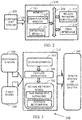
- FIG. 2 illustrates an implementation of an AI based health management system 210 for monitoring health of a host system 230, in accordance with an example embodiment.
- the host system 230 may include, but are not limited to vehicle systems, aircraft, automotive, turbine engines, and so on.
- the host system 230 may include a plurality of subsystems (or system components).
- one or more subsystems of the plurality of subsystem (or system components) may become faulty, and affect the heath of the entire host system 230.
- the health management system 210 is configured to receive system response 240 from the host system 230, and provide real-time diagnostic and prognostic health management of the host system 230.
- the system response 240 is indicative of the system-level performance of the host system 230.
- the health management system 210 includes or is otherwise in communication with at least one processor such as a processor 212, at least one memory such as a memory 214, and a user interface 216.
- the processor 212, the memory 214, and the user interface 216 may be coupled by a system bus such as a system bus 218 or a similar mechanism.
- FIG. 2 shows example components of health management system 210, in other implementations, health management system 210 may contain fewer components, additional components, different components, or differently arranged components than depicted in FIG. 2 .
- the processor 212 may include circuitry implementing, among others, logic functions associated with the computation and control functions of the health management system 210.
- the neural network controller 212 may include, but are not limited to, one or more digital signal processors (DSPs), one or more microprocessor, one or more special-purpose computer chips, one or more field-programmable gate arrays (FPGAs), one or more application-specific integrated circuits (ASICs), one or more computer(s), various analog to digital converters, digital to analog converters, and/or other support circuits.
- DSPs digital signal processors
- FPGAs field-programmable gate arrays
- ASICs application-specific integrated circuits
- Examples of the neural network controller may include, but are not limited to, Raspberry PiTM controller, iOSTM controller, and the like.
- the processor 212 may also include the functionality to encode messages and/or data or information.
- the processor 212 may include, among other things, a clock, an arithmetic logic unit (ALU) and logic gates configured to support operation of the processor 212. Further, the processor 212 may include functionality to execute one or more software programs, which may be stored in the memory 214 or otherwise accessible to the processor 212.
- ALU arithmetic logic unit
- the memory 214 may store any number of pieces of information, and data, used by the health management system 210 to implement the functions of the health management system 210.
- the memory 214 may include for example, volatile memory and/or non-volatile memory. Examples of volatile memory may include, but are not limited to volatile random access memory (RAM).
- the non-volatile memory may additionally or alternatively comprise an electrically erasable programmable read only memory (EEPROM), flash memory, hard drive, or the like.
- EEPROM electrically erasable programmable read only memory
- the memory 204 may be configured to store information, data, applications, instructions or the like for enabling the health management system 210 to carry out various functions in accordance with various example embodiments.
- non-volatile memory includes, but are not limited to, hard disks, magnetic tapes, optical disks, programmable read only memory, erasable programmable read only memory, electrically erasable programmable read only memory, flash memory, and the like.
- the memory 214 may be configured to store information, data, applications, instructions or the like for enabling the system 200 to carry out various functions in accordance with various example embodiments. Additionally or alternatively, the memory 214 may be configured to store instructions which when executed by the processor 212 causes the health management system 210 to behave in a manner as described in various embodiments.
- the memory 214 may include an identification module 220 for identification of abnormal condition based on the system level response 240. Addition, the memory 214 may include a detection module 222 for identifying a failed component/sub-system that may have led to observable abnormality in the system response (root cause).
- the user interface 206 may include an output device such as a ringer, an earphone or speaker, a microphone, a display, and an input interface.
- the input interface is configured to receive an indication of a user input for simulating fault scenarios in the health management system. Examples of the input interface may include, but are not limited to, a keyboard, a mouse, a joystick, a keypad, a touch screen, soft keys, and the like.
- the output user interface provides an audible, visual, mechanical or other output and/or feedback to the user based on the simulation. Examples of the output interface may include, but are not limited to, a display, a microphone, a speaker, ringers, vibrators, and the like.
- the user interface 216 may include, among other devices or elements, any or all of a speaker, a microphone, a display, and a keyboard, touch screen, or the like.
- the user interface 216 may be in communication with the processor 212.
- the processor 212 may comprise user interface circuitry configured to control at least some functions of one or more elements of the user interface 216.
- the processor 212 and/or user interface circuitry comprising the processor 212 may be configured to control one or more functions of one or more elements of the user interface 216 through computer program instructions, for example, software and/or firmware, stored on a memory, for example, the memory 214, and/or the like, accessible to the processor 212.
- the user interface 216 allows communication to and from a system operator, an operator of the vehicle and/or other systems such as the host system 230.
- the processor 212 along with memory 214 and other components of the health management system 210 (hereinafter referred to as system 210) may be configured to identify one or more failed subsystems of the host system 230.
- the failed subsystem of a host system 230 is identified by monitoring the system level performance/response 240 of the host system 230.
- the state of the host system 230 may be determined based on a diagnostic management.
- the diagnostic management of the system level response may be performed by the neural network controller (or the processor) 212 of the health management system 210.
- the controller is an artificial intelligence controller.
- the processor 212 along with memory 214 and other components of the system 210 is configured to detect any abnormal working condition based on the system level response 240.
- the processor 212 is configured to identify a failed component or sub-system that may have led to observable abnormality in the system response (root cause).
- the diagnostic management performed by the processor 212 is based on observed system states, applying past performance knowledge, and/or based on expertise built over a period.
- the processor 212 along with memory 214 and other components of the system 210 is configured to monitor a plurality of unique patterns associated with system level performance/response 240 of the host system generated in real-time.
- the plurality of unique patterns includes responses associated with a set of system parameters of the host system 230.
- the system parameters may include one or more of input parameters, control parameters, feedback parameters, output parameters, and so on.
- the set of system parameters includes only a subset of a plurality of system parameters of the host system, and a key feature of the various embodiments of the present disclosure is that the disclosed system is capable of determining one or more failed subsystem/potential anomalies in the host system by determination of system level response generated based only on the set of system parameters (and not on the plurality of system parameters). Accordingly, the disclosed system can effectively manage the health of the host system in a computationally efficient manner.
- the processor 212 along with memory 214 and other components of the system 210 is configured to compare the plurality of unique patterns with a plurality of predetermined patterns corresponding to the plurality of system parameters to detect one or more potential anomalies in the host system and at least one faulty subsystem responsible for contributing to the potential anomalies in the host system.
- the plurality of predetermined patterns are preconfigured by training a neural network model.
- the processor 202 along with memory 204 and other components of the system 210 preconfigure the plurality of predetermined patterns by acquiring a training data.
- the training data includes the system-level performance under a normal and a plurality of abnormal working conditions of the plurality of subsystems.
- the processor 212 along with memory 214 and other components of the system 210 are further configured to extract a plurality of feature vectors from the training data.
- the plurality of feature vectors exhibits the plurality of predetermined patterns indicative of the one or more anomalies in the host system. Additionally, the plurality of predetermined patterns may also indicate the faulty subsystems that may be associated with an anomaly or a potential anomaly.
- the processor 212 along with memory 214 and other components of the system 210 are configured to train an artificial intelligence model, for example a neural network model based on the plurality of feature vectors to classify the one or more anomalies with the one or more corresponding subsystems responsible for contributing to the one or more potential anomalies.
- an artificial intelligence model for example a neural network model based on the plurality of feature vectors to classify the one or more anomalies with the one or more corresponding subsystems responsible for contributing to the one or more potential anomalies.
- FIG. 3 A detailed functional model of various modules of the health management system 210 is illustrated and described further with reference to FIG. 3 .
- FIG. 3 illustrates a block diagram 300 of an artificial intelligence based health management system, in accordance with an example embodiment.
- the artificial intelligence based health management system 300 may hereinafter be referred to as system 300.
- the system 300 may be an example of the health management system 210 ( FIG. 2 ).
- the system 300 is configured to derive the health status of a plurality of subsystems of a host system based on the monitoring of the system level responses of the host system.
- the system 300 is further configured to derive distinguishing features from the overall system level response through feature extraction methodologies.
- the system is configured to provide said features to a decision making frameworks.
- the decision making frameworks may include an AI model that is configured to learn the host system as well as generalize the model so that it could be applied to diagnose unseen cases that are critical and difficult to address through conventional algorithm based approach.
- the decision making frameworks may be implemented using Neural Networks (NN).
- the functional block diagram 300 illustrates various functional modules of the health management system.
- the system performance is simulated for normal and abnormal scenarios, and further acquires and processes the response (for example, the system response 240 of FIG. 2 ).
- the simulation data is utilized for the training of the health management system.
- a pictorial depiction of a normal response and an abnormal response is already described with reference to FIG. 1 .
- the data acquisition facilitates in detection and identification of abnormal response.
- 'detection' may refer to an ability to distinguish normal and abnormal performance of the host system based on domain experience and training (system failure modes and their effects), taking care of many operational conditions.
- the 'identification' may refer to an ability to identify the failed component that can lead to such observable abnormality in the system response (root cause).
- detection of the abnormal response and identification of the faulty subsystem may be performed by simulating the failure modes of various sub-systems and generating the system response under various normal and abnormal conditions.
- the training data is used for the training of the health management system.
- a replica of the system or a reference system (such as reference system 320) may be configured where different fault scenarios may be introduced for analysis of the system response.
- the fault scenarios may be introduced by a fault model such as a fault model 330.
- the system level outputs of both the reference system 320 as well as the fault model 330 may be captured continuously in a specified window of time scale and preprocessed to remove trends in data so as to process unique signals.
- the features (or feature vectors) from the data are extracted that can be used for training the health management system.
- various statistical and signal processing functions are applied on the data to extract the features.
- These feature vectors exhibit unique patters or signatures that can be analyzed for various fault scenarios.
- the feature vectors are used as inputs to the neural network model and are trained to classify the failures with the associated root causes by leveraging domain knowledge. Once trained extensively and the generalization is achieved the network is deployed on a target hardware to accept signals in real time.
- the feature extraction module may implement a plurality of algorithms for feature extraction.
- RMS Root Mean Square
- STFT Short Time Fourier Transform
- FFT Fast Fourier Transform
- DWT Discrete Wavelength Transform
- DTFT Discrete Time Fourier Transform
- the feature vectors are inputs to artificial intelligence network such as the neural networks.
- the artificial intelligence network is trained to classify the faulty scenarios/failures with the associated root causes by leveraging domain knowledge. Once trained, the artificial intelligence network could be deployed on the hardware along with the system under operation for predicting the future time series.
- the failure classification artificial intelligence network designed earlier is applied to the time predictive neural network to know not only that an anomaly would occur but also which component or components in the subsystem would contribute to the failures.
- the health management system utilizes the strengths of the artificial intelligence networks such as the neural networks to learn a host system as well as generalize the model so that it could be applied to diagnose unseen cases that are critical and difficult to address through conventional algorithm based approach.
- the output of classification of the faulty scenarios/failures being performed by the artificial intelligence networks is provided at a user interface, for example, UI 216 of the health management system.
- a user interface for example, UI 216 of the health management system.
- Example screenshots illustrating the user interfaces of the health management system are described further with reference to FIGS. 5A and 5B .
- FIG. 4 illustrates a flowchart 400 of an example method for health management of a host system, in accordance with an example embodiment.
- a plurality of unique patterns including responses associated with a plurality of system parameters of the host system is monitored.
- the unique patterns may be generated in real-time.
- the plurality of system parameters is indicative of a system-level performance of the host system.
- the system (for example, the system 200/300) may monitor the unique patterns.
- the method includes comparing the plurality of unique patterns with a plurality of predetermined patterns corresponding to the plurality of system parameters to detect one or more potential anomalies in the host system and at least one faulty subsystems of the plurality of subsystems.
- the plurality of predetermined patterns are obtained based on a training of a neural network based controller by a training data (as described with reference to FIG. 3 ).
- the training data is acquired pertaining to system level response under various normal and abnormal conditions of a host. The acquired data is used for training of the health management system (in particular, controller of the health management system).
- a replica of the system may be made where different fault scenarios can be introduced for analysis of the system response.
- the system level outputs of both the reference as well as the fault introduced model are captured continuously in a specified window of time scale and preprocessed to remove trends in data so as to process unique signals.
- a plurality of features is extracted from the acquired data.
- statistical and signal processing functions are applied on the data to extract the features that exhibit signatures which could be analyzed for various fault scenarios.
- the extracted feature-vectors are used as inputs to neural networks and are neural networks are trained to classify the failures with the associated root causes by leveraging domain knowledge.
- the neural networks are trained for pattern recognition of various fault signatures.
- the trained neural network can be deployed on the hardware along with the system under operation to identify the potential anomalies in the host system as well as the faulty subsystems responsible for contributing to the one or more potential anomalies in the host system.
- FIGS. 5A and 5B illustrate exemplary screenshots of a health management system in normal scenarios and abnormal scenarios respectively, in accordance with an example embodiment.
- the screenshot illustrated in FIGS. 5A and 5B represent graphical user interface (GUI) for failure mode simulations, for a host system such as an on-board flight system.
- GUI graphical user interface
- the GUI includes multiple windows such as windows 502, 504, and 506 for showing simulation settings, flight performance deviations from reference model and overall system health, respectively.
- the window 502 provides an interface for inputting various simulation parameters.
- the window 504 illustrates smooth responses without any deviations.
- the window 506 depicting the overall system health provides status such as 'All systems are healthy'.
- the window 504 illustrates a responses with deviations.
- the window 506 depicts the overall system health provides status pertaining to failure of specific system components/subsystems.
- the dashboard may alert the user/pilot about the root cause in case of a fault scenario by flashing a warning in the window 506. It will be understood that the alert may be provided by any know techniques/ways without limiting the scope of various embodiments.
- control actuators and sensors may be selected as candidate subsystems which may develop fault during a flight.
- the fault in these subsystems due to reasons such as leakage of hydraulic fluid/ crack in the manifold etc., result in the dynamics performance parameters such as speed of response, damping coefficient, etc..
- the faults are simulated in the health management system by varying these parameters beyond the design tolerances. As the simulation is run in non-real time environment, the faults are programmed to occur at some specified time of the flight.
- Various embodiments of the disclosure provide method and system for health management of host systems. For example, various embodiments provides methods for observing only a limited set of system level response of the overall system and then come up with an understanding of the fault behaviors of all the critical sub components of the system. The method avoids the need for additional sensors to learn more parameters of an existing host system. In addition, the method aims at creating an on board system that works in cohesion with the system under operation and performs diagnostics as well as prognosis on the subsystem level components.
- the invention is also directed to computer-readable storage means containing program-code means for implementation of all the steps of the method according to claim 6, when the program runs on a server or mobile device or any suitable programmable device.
- the hardware device can be any kind of device which can be programmed including e.g. any kind of computer like a server or a personal computer, or the like, or any combination thereof.
- the device may also include means which could be e.g. hardware means like e.g. an application-specific integrated circuit (ASIC), a field-programmable gate array (FPGA), or a combination of hardware and software means, e.g. an ASIC and an FPGA, or at least one microprocessor and at least one memory with software modules located therein.
- the means can include both hardware means and software means.
- the method embodiments described herein could be implemented in hardware and software.
- the device may also include software means. Alternatively, the embodiments may be implemented on different hardware devices, e.g. using a plurality of CPUs.
- the embodiments herein can comprise hardware and software elements.
- the embodiments that are implemented in software include but are not limited to, firmware, resident software, microcode, etc.
- the functions performed by various modules described herein may be implemented in other modules or combinations of other modules.
- a computer-usable or computer readable medium can be any apparatus that can comprise, store, communicate, propagate, or transport the program for use by or in connection with the instruction execution system, apparatus, or device.
Landscapes
- Engineering & Computer Science (AREA)
- Physics & Mathematics (AREA)
- Theoretical Computer Science (AREA)
- General Physics & Mathematics (AREA)
- General Engineering & Computer Science (AREA)
- Artificial Intelligence (AREA)
- Evolutionary Computation (AREA)
- Mathematical Physics (AREA)
- Software Systems (AREA)
- Data Mining & Analysis (AREA)
- Computing Systems (AREA)
- Automation & Control Theory (AREA)
- Molecular Biology (AREA)
- Computer Hardware Design (AREA)
- Biophysics (AREA)
- Biomedical Technology (AREA)
- Life Sciences & Earth Sciences (AREA)
- Health & Medical Sciences (AREA)
- Computational Linguistics (AREA)
- General Health & Medical Sciences (AREA)
- Quality & Reliability (AREA)
- Computer Vision & Pattern Recognition (AREA)
- Medical Informatics (AREA)
- Testing And Monitoring For Control Systems (AREA)
- Debugging And Monitoring (AREA)
- Management, Administration, Business Operations System, And Electronic Commerce (AREA)
Claims (11)
- Système de gestion de la santé (210) pour un diagnostic et un pronostic d'un système hôte (110), le système hôte (110) présentant une pluralité de sous-systèmes, dans lequel le système de gestion de la santé (210) comprend :une mémoire (214) destinée à stocker des instructions et une pluralité de motifs prédéterminés ; etun contrôleur de réseau de neurones (212) couplé à la mémoire (214), dans lequel le contrôleur de réseau de neurones (212) est configuré par les instructions de manière à :surveiller une pluralité de motifs uniques générée en temps réel, correspondant à un ensemble de paramètres système du système hôte (110), dans lequel les paramètres système comprennent au moins l'un d'un ou plusieurs paramètres parmi des paramètres d'entrée, des paramètres de commande, des paramètres de rétroaction et des paramètres de sortie, dans lequel les motifs uniques sont indicatifs de la performance au niveau système du système hôte en temps réel, et chacun des motifs uniques est unique pour un sous-système respectif du système hôte, dans lequel les motifs uniques permettent l'identification de défauts associés à un ou plusieurs sous-systèmes, sans dépendre de capteurs physiques pour détecter un défaut dans le sous-système, et dans lequel l'ensemble de paramètres système inclut uniquement un sous-ensemble d'une pluralité de paramètres système du système hôte (110) ;préconfigurer la pluralité de motifs prédéterminés, et dans lequel, pour préconfigurer la pluralité de motifs prédéterminés, le contrôleur de réseau de neurones (212) est configuré par les instructions de manière à :acquérir des données d'apprentissage comprenant la performance au niveau système du système hôte dans un état de fonctionnement normal de la pluralité de sous-systèmes etdans une pluralité d'états de fonctionnement anormaux dudit un ou desdits plusieurs sous-systèmes de la pluralité de sous-systèmes ; etextraire une pluralité de vecteurs de caractéristiques des données d'apprentissage, la pluralité de vecteurs de caractéristiques présentant la pluralité de motifs prédéterminés indicatifs d'une ou plusieurs anomalies potentielles dans le système hôte ;comparer la pluralité de motifs uniques à la pluralité de motifs prédéterminés correspondant à l'ensemble de paramètres système ; etdétecter une ou plusieurs anomalies potentielles dans le système hôte (110) et au moins un sous-système défectueux parmi la pluralité de sous-systèmes, sur la base de la comparaison, dans lequel ledit au moins un sous-système défectueux est responsable de contribuer à ladite une ou auxdites plusieurs anomalies potentielles dans le système hôte.
- Système de gestion de la santé (210) selon la revendication 1, dans lequel le contrôleur de réseau de neurones (212) est en outre configuré par les instructions de manière à entraîner un modèle de réseau de neurones, sur la base de la pluralité de vecteurs de caractéristiques, à classer ladite une ou lesdites plusieurs anomalies potentielles avec ledit au moins un sous-système défectueux responsable de contribuer à ladite une ou auxdites plusieurs anomalies potentielles.
- Système de gestion de la santé (210) selon la revendication 1, dans lequel, pour acquérir les données d'apprentissage, le contrôleur de réseau de neurones (212) est en outre configuré par les instructions de manière à :simuler l'état de fonctionnement normal de la pluralité de sous-systèmes et la pluralité d'états de fonctionnement anormaux dudit un ou desdits plusieurs sous-systèmes de la pluralité de sous-systèmes ; etgénérer la performance au niveau système dans les états de fonctionnement normaux et dans la pluralité d'états de fonctionnement anormaux.
- Système de gestion de la santé (210) selon la revendication 3, dans lequel, pour simuler l'état de fonctionnement normal de la pluralité de sous-systèmes et la pluralité d'états de fonctionnement anormaux dudit un ou desdits plusieurs sous-systèmes de la pluralité de sous-systèmes, le contrôleur de réseau de neurones (212) est en outre configuré par les instructions de manière à :capturer la performance au niveau système à partir d'un modèle de référence et d'un modèle à défaut introduit, en continu, dans une fenêtre spécifiée d'échelle de temps, dans lequel le modèle de référence comprend la modélisation de l'état de fonctionnement normal dudit un ou desdits plusieurs sous-systèmes, et le modèle à défaut introduit comprend la modélisation de la pluralité d'états de fonctionnement anormaux dudit un ou desdits plusieurs sous-systèmes de la pluralité de sous-systèmes ; etprétraiter les réponses au niveau système pour éliminer des tendances dans des données d'apprentissage.
- Système de gestion de la santé (210) selon la revendication 1, dans lequel le système hôte (110) comprend un système parmi un système d'aéronef, un système automobile, un système de turbine et un système de moteur.
- Procédé mis en œuvre par ordinateur pour la gestion de la santé d'un système hôte (110) par un système de gestion de la santé (210), le système hôte (110) présentant une pluralité de sous-systèmes, dans lequel le procédé comprend :
la mise en service du système de gestion de la santé (210) comprenant :
une mémoire (214) destinée à stocker des instructions et une pluralité de motifs prédéterminés, et un contrôleur de réseau de neurones couplé à la mémoire (214), dans lequel le contrôleur de réseau de neurones (212) est configuré par les instructions de manière à :surveiller, par le biais du contrôleur de réseau de neurones (212), une pluralité de motifs uniques générée en temps réel, correspondant à un ensemble de paramètres système du système hôte (110), dans lequel les paramètres système comprennent au moins l'un d'un ou plusieurs paramètres parmi des paramètres d'entrée, des paramètres de commande, des paramètres de rétroaction et des paramètres de sortie, dans lequel les motifs uniques sont indicatifs de la performance au niveau système du système hôte (110) en temps réel, et chacun des motifs uniques est unique pour un sous-système respectif du système hôte, dans lequel les motifs uniques permettent l'identification de défauts associés à un ou plusieurs sous-systèmes, sans dépendre de capteurs physiques pour détecter un défaut dans le sous-système, et dans lequel l'ensemble de paramètres système inclut uniquement un sous-ensemble d'une pluralité de paramètres système du système hôte (110) ;préconfigurer la pluralité de motifs prédéterminés, et dans lequel, l'étape de préconfiguration de la pluralité de motifs prédéterminés comprend les étapes ci-dessous consistant à :acquérir des données d'apprentissage comprenant la performance au niveau système du système hôte (110) dans un état de fonctionnement normal de la pluralité de sous-systèmes et dans une pluralité d'états de fonctionnement anormaux dudit un ou desdits plusieurs sous-systèmes de la pluralité de sous-systèmes ; etextraire une pluralité de vecteurs de caractéristiques des données d'apprentissage, la pluralité de vecteurs de caractéristiques présentant la pluralité de motifs prédéterminés indicatifs d'une ou plusieurs anomalies potentielles dans le système hôte (110) ;comparer, par le biais du contrôleur de réseau de neurones (212), la pluralité de motifs uniques à la pluralité de motifs prédéterminés correspondant à l'ensemble de paramètres système ; etdétecter, par le biais du contrôleur de réseau de neurones (212), une ou plusieurs anomalies potentielles dans le système hôte (110) et au moins un sous-système défectueux parmi la pluralité de sous-systèmes, sur la base de la comparaison, dans lequel ledit au moins un sous-système défectueux est responsable de contribuer à ladite une ou auxdites plusieurs anomalies potentielles dans le système hôte (110). - Procédé selon la revendication 6, comprenant en outre l'étape consistant à entraîner un modèle de réseau de neurones, sur la base de la pluralité de vecteurs de caractéristiques, à classer ladite une ou lesdites plusieurs anomalies potentielles avec ledit au moins un sous-système défectueux responsable de contribuer à ladite une ou auxdites plusieurs anomalies potentielles.
- Procédé selon la revendication 6, dans lequel l'étape d'acquisition des données d'apprentissage comprend les étapes ci-dessous consistant à :simuler l'état de fonctionnement normal de la pluralité de sous-systèmes et la pluralité d'états de fonctionnement anormaux dudit un ou desdits plusieurs sous-systèmes de la pluralité de sous-systèmes ; etgénérer la performance au niveau système dans les états de fonctionnement normaux et dans la pluralité d'états de fonctionnement anormaux.
- Procédé selon la revendication 8, dans lequel l'étape de simulation de l'état de fonctionnement normal de la pluralité de sous-systèmes et de la pluralité d'états de fonctionnement anormaux dudit un ou desdits plusieurs sous-systèmes de la pluralité de sous-systèmes comprend les étapes ci-dessous consistant à :capturer la performance au niveau système à partir d'un modèle de référence et d'un modèle à défaut introduit, en continu, dans une fenêtre spécifiée d'échelle de temps, dans lequel le modèle de référence comprend la modélisation de l'état de fonctionnement normal dudit un ou desdits plusieurs sous-systèmes, et le modèle à défaut introduit comprend la modélisation de la pluralité d'états de fonctionnement anormaux dudit un ou desdits plusieurs sous-systèmes de la pluralité de sous-systèmes ; etprétraiter les réponses au niveau système pour éliminer des tendances dans des données d'apprentissage.
- Procédé selon la revendication 6, dans lequel le système hôte (110) comprend un système parmi un système d'aéronef, un système automobile, un système de turbine et un système de moteur.
- Support non transitoire lisible par ordinateur sur lequel est incorporé un programme informatique pour exécuter un procédé de gestion de la santé d'un système hôte (110) par le biais d'un système de gestion de la santé (210), le système hôte (110) présentant une pluralité de sous-systèmes, et dans lequel le système de gestion de la santé (210) comprend une mémoire (214) pour stocker des instructions et une pluralité de motifs prédéterminés, et un contrôleur de réseau de neurones (212) couplé à la mémoire (214), le procédé comprenant les étapes ci-dessous consistant à :surveiller une pluralité de motifs uniques générée en temps réel, correspondant à un ensemble de paramètres système du système hôte (110), dans lequel les paramètres système comprennent au moins l'un d'un ou plusieurs paramètres parmi des paramètres d'entrée, des paramètres de commande, des paramètres de rétroaction et des paramètres de sortie, dans lequel les motifs uniques sont indicatifs de la performance au niveau système du système hôte (110) en temps réel, et chacun des motifs uniques est unique pour un sous-système respectif du système hôte, dans lequel les motifs uniques permettent l'identification de défauts associés à un ou plusieurs sous-systèmes, sans dépendre de capteurs physiques pour détecter un défaut dans le sous-système, et dans lequel l'ensemble de paramètres système inclut uniquement un sous-ensemble d'une pluralité de paramètres système du système hôte (110) ;préconfigurer la pluralité de motifs prédéterminés, et dans lequel, l'étape de préconfiguration de la pluralité de motifs prédéterminés, comprend les étapes ci-dessous consistant à :acquérir des données d'apprentissage comprenant la performance au niveau système du système hôte (110) dans un état de fonctionnement normal de la pluralité de sous-systèmes et dans une pluralité d'états de fonctionnement anormaux dudit un ou desdits plusieurs sous-systèmes de la pluralité de sous-systèmes ; etextraire une pluralité de vecteurs de caractéristiques des données d'apprentissage, la pluralité de vecteurs de caractéristiques présentant la pluralité de motifs prédéterminés indicatifs d'une ou plusieurs anomalies potentielles dans le système hôte (110) ;comparer la pluralité de motifs uniques à la pluralité de motifs prédéterminés correspondant à l'ensemble de paramètres système ; etdétecter une ou plusieurs anomalies potentielles dans le système hôte (110) et au moins un sous-système défectueux parmi la pluralité de sous-systèmes, sur la base de la comparaison, dans lequel ledit au moins un sous-système défectueux est responsable de contribuer à ladite une ou auxdites plusieurs anomalies potentielles dans le système hôte (110).
Applications Claiming Priority (1)
| Application Number | Priority Date | Filing Date | Title |
|---|---|---|---|
| IN2066MU2015 | 2015-05-27 |
Publications (2)
| Publication Number | Publication Date |
|---|---|
| EP3098681A1 EP3098681A1 (fr) | 2016-11-30 |
| EP3098681B1 true EP3098681B1 (fr) | 2020-08-26 |
Family
ID=55542461
Family Applications (1)
| Application Number | Title | Priority Date | Filing Date |
|---|---|---|---|
| EP16160362.6A Active EP3098681B1 (fr) | 2015-05-27 | 2016-03-15 | Gestion de la santé d'intelligence artificielle de système hôte |
Country Status (3)
| Country | Link |
|---|---|
| US (1) | US10089203B2 (fr) |
| EP (1) | EP3098681B1 (fr) |
| JP (1) | JP6774768B2 (fr) |
Cited By (1)
| Publication number | Priority date | Publication date | Assignee | Title |
|---|---|---|---|---|
| DE102022003261A1 (de) | 2022-09-06 | 2024-01-11 | Mercedes-Benz Group AG | Schaltungsanordnung und Verfahren zur Erkennung eines Gesundheitsstatus von elektrischen Verbrauchern |
Families Citing this family (29)
| Publication number | Priority date | Publication date | Assignee | Title |
|---|---|---|---|---|
| US10708151B2 (en) * | 2015-10-22 | 2020-07-07 | Level 3 Communications, Llc | System and methods for adaptive notification and ticketing |
| GB2546253B (en) * | 2016-01-06 | 2020-04-22 | Ge Aviat Systems Ltd | Fusion of aviation-related data for comprehensive aircraft system health monitoring |
| US10304263B2 (en) * | 2016-12-13 | 2019-05-28 | The Boeing Company | Vehicle system prognosis device and method |
| US10247032B2 (en) | 2017-03-28 | 2019-04-02 | Honeywell International Inc. | Gas turbine engine and test cell real-time diagnostic fault detection and corrective action system and method |
| CN107025341A (zh) * | 2017-03-30 | 2017-08-08 | 河海大学 | 一种光伏逆变器故障诊断方法 |
| US10580228B2 (en) * | 2017-07-07 | 2020-03-03 | The Boeing Company | Fault detection system and method for vehicle system prognosis |
| EP3444724B1 (fr) * | 2017-08-18 | 2023-12-20 | Tata Consultancy Services Limited | Procédé et système de surveillance de la santé et d'identification de signature de défaut |
| US10600261B2 (en) * | 2017-10-05 | 2020-03-24 | GM Global Technology Operations LLC | Vehicle with health-based active self-testing method |
| US10719772B2 (en) * | 2017-10-27 | 2020-07-21 | The Boeing Company | Unsupervised multivariate relational fault detection system for a vehicle and method therefor |
| US10606678B2 (en) | 2017-11-17 | 2020-03-31 | Tesla, Inc. | System and method for handling errors in a vehicle neural network processor |
| CN108304960A (zh) * | 2017-12-29 | 2018-07-20 | 中车工业研究院有限公司 | 一种轨道交通设备故障诊断方法 |
| US11003561B2 (en) * | 2018-01-03 | 2021-05-11 | Dell Products L.P. | Systems and methods for predicting information handling resource failures using deep recurrent neural networks |
| US11049033B2 (en) | 2018-01-12 | 2021-06-29 | Cisco Technology, Inc. | Deriving highly interpretable cognitive patterns for network assurance |
| US10547518B2 (en) | 2018-01-26 | 2020-01-28 | Cisco Technology, Inc. | Detecting transient vs. perpetual network behavioral patterns using machine learning |
| CN108427400B (zh) * | 2018-03-27 | 2020-07-03 | 西北工业大学 | 一种基于神经网络解析冗余的飞机空速管故障诊断方法 |
| KR102472134B1 (ko) * | 2018-03-29 | 2022-11-29 | 삼성전자주식회사 | 심층학습을 기반으로 한 설비 진단 시스템 및 방법 |
| US10496084B2 (en) * | 2018-04-06 | 2019-12-03 | Oracle International Corporation | Dequantizing low-resolution IoT signals to produce high-accuracy prognostic indicators |
| US11151810B2 (en) | 2018-10-12 | 2021-10-19 | Aurora Flight Sciences Corporation | Adaptable vehicle monitoring system |
| US11358737B2 (en) | 2018-12-07 | 2022-06-14 | The Boeing Company | Methods and systems for performing aircraft maintenance |
| BR112021010468A2 (pt) * | 2018-12-31 | 2021-08-24 | Intel Corporation | Sistemas de segurança que empregam inteligência artificial |
| CN109782747B (zh) * | 2019-02-15 | 2020-08-28 | 四川阿尔特新能源汽车有限公司 | 故障检测方法及装置 |
| US11248989B2 (en) | 2019-06-21 | 2022-02-15 | Raytheon Technologies Corporation | System and method for analyzing engine test data in real time |
| CN110458039A (zh) * | 2019-07-19 | 2019-11-15 | 华中科技大学 | 一种工业过程故障诊断模型的构建方法及其应用 |
| US11227209B2 (en) * | 2019-07-31 | 2022-01-18 | Dell Products L.P. | Systems and methods for predicting information handling resource failures using deep recurrent neural network with a modified gated recurrent unit having missing data imputation |
| US20210182386A1 (en) * | 2019-12-11 | 2021-06-17 | Samsung Electronics Co., Ltd. | Electronic apparatus that monitors a safety function and a controlling method thereof |
| WO2022069258A1 (fr) * | 2020-09-30 | 2022-04-07 | Siemens Aktiengesellschaft | Dispositif et procédé de détection d'anomalies dans une installation industrielle pour l'exécution d'un processus de production |
| KR20220071618A (ko) * | 2020-11-24 | 2022-05-31 | 삼성전자주식회사 | 컨벌루션 연산을 위한 데이터 공유 방법, 페처 및 컨벌루션 연산 장치 |
| CN112380782A (zh) * | 2020-12-07 | 2021-02-19 | 重庆忽米网络科技有限公司 | 一种基于混合指标和神经网络的旋转设备故障预测方法 |
| CN116684327B (zh) * | 2023-08-03 | 2023-10-27 | 中维建技术有限公司 | 一种基于云计算的山林地区通信网络故障监测评估方法 |
Citations (2)
| Publication number | Priority date | Publication date | Assignee | Title |
|---|---|---|---|---|
| US5919267A (en) * | 1997-04-09 | 1999-07-06 | Mcdonnell Douglas Corporation | Neural network fault diagnostics systems and related method |
| US20140039834A1 (en) * | 2012-08-01 | 2014-02-06 | Hitachi Power Solutions Co., Ltd. | Method and apparatus for monitoring equipment conditions |
Family Cites Families (14)
| Publication number | Priority date | Publication date | Assignee | Title |
|---|---|---|---|---|
| US5402521A (en) * | 1990-02-28 | 1995-03-28 | Chiyoda Corporation | Method for recognition of abnormal conditions using neural networks |
| JPH04238224A (ja) * | 1991-01-22 | 1992-08-26 | Toshiba Corp | プラント診断装置 |
| US5544308A (en) | 1994-08-02 | 1996-08-06 | Giordano Automation Corp. | Method for automating the development and execution of diagnostic reasoning software in products and processes |
| JPH08226411A (ja) * | 1995-02-21 | 1996-09-03 | Nippon Steel Corp | 油圧回路の故障原因機器探索方法及びその装置 |
| US6138109A (en) * | 1997-12-23 | 2000-10-24 | Caterpillar Inc. | Neural network diagnostic classification of complex binary systems |
| US6105149A (en) * | 1998-03-30 | 2000-08-15 | General Electric Company | System and method for diagnosing and validating a machine using waveform data |
| US6898554B2 (en) * | 2000-06-12 | 2005-05-24 | Scientific Monitoring, Inc. | Fault detection in a physical system |
| JP2003050631A (ja) * | 2001-08-07 | 2003-02-21 | Mitsui Eng & Shipbuild Co Ltd | 異常診断システムの学習データ生成方法、異常診断システムの構築プログラム、異常診断プログラム、異常診断システムの構築装置および異常診断システム |
| US7499777B2 (en) | 2005-04-08 | 2009-03-03 | Caterpillar Inc. | Diagnostic and prognostic method and system |
| US7233932B2 (en) * | 2005-05-31 | 2007-06-19 | Honeywell International, Inc. | Fault detection system and method using approximate null space base fault signature classification |
| JP4886460B2 (ja) * | 2006-10-12 | 2012-02-29 | パナソニック電工Sunx株式会社 | 異常監視装置 |
| US8255100B2 (en) * | 2008-02-27 | 2012-08-28 | The Boeing Company | Data-driven anomaly detection to anticipate flight deck effects |
| US20130060524A1 (en) * | 2010-12-01 | 2013-03-07 | Siemens Corporation | Machine Anomaly Detection and Diagnosis Incorporating Operational Data |
| US20130030765A1 (en) * | 2011-07-27 | 2013-01-31 | Danni David | System and method for use in monitoring machines |
-
2016
- 2016-03-15 EP EP16160362.6A patent/EP3098681B1/fr active Active
- 2016-03-18 US US15/074,549 patent/US10089203B2/en not_active Expired - Fee Related
- 2016-03-24 JP JP2016059399A patent/JP6774768B2/ja active Active
Patent Citations (2)
| Publication number | Priority date | Publication date | Assignee | Title |
|---|---|---|---|---|
| US5919267A (en) * | 1997-04-09 | 1999-07-06 | Mcdonnell Douglas Corporation | Neural network fault diagnostics systems and related method |
| US20140039834A1 (en) * | 2012-08-01 | 2014-02-06 | Hitachi Power Solutions Co., Ltd. | Method and apparatus for monitoring equipment conditions |
Cited By (2)
| Publication number | Priority date | Publication date | Assignee | Title |
|---|---|---|---|---|
| DE102022003261A1 (de) | 2022-09-06 | 2024-01-11 | Mercedes-Benz Group AG | Schaltungsanordnung und Verfahren zur Erkennung eines Gesundheitsstatus von elektrischen Verbrauchern |
| WO2024052183A1 (fr) | 2022-09-06 | 2024-03-14 | Mercedes-Benz Group AG | Agencement de circuit et procédé de détection d'un état de santé de charges électriques |
Also Published As
| Publication number | Publication date |
|---|---|
| EP3098681A1 (fr) | 2016-11-30 |
| JP6774768B2 (ja) | 2020-10-28 |
| US20160350194A1 (en) | 2016-12-01 |
| US10089203B2 (en) | 2018-10-02 |
| JP2016224913A (ja) | 2016-12-28 |
Similar Documents
| Publication | Publication Date | Title |
|---|---|---|
| EP3098681B1 (fr) | Gestion de la santé d'intelligence artificielle de système hôte | |
| Schlegel et al. | Towards a rigorous evaluation of XAI methods on time series | |
| Byington et al. | Data-driven neural network methodology to remaining life predictions for aircraft actuator components | |
| EP1729243A1 (fr) | Système de détection de l'erreur et procédé utilisant la classification de la signature de l'erreur basée sur l'espace nul avoisinant | |
| CN111709447A (zh) | 电网异常检测方法、装置、计算机设备和存储介质 | |
| KR20170125265A (ko) | 플랜트 이상 감지를 위한 자동 학습 시스템 및 방법 | |
| CN111679960B (zh) | 一种可靠性、弹性、脆性的系统状态评估方法 | |
| KR102321607B1 (ko) | 기계의 결함 검출 장치 및 방법 | |
| KR20200001910A (ko) | 발전소 고장 예측 및 진단시스템의 학습모델을 위한 학습데이터 생성장치 및 방법 | |
| Zhang et al. | Selecting optimal features for cross-fleet analysis and fault diagnosis of industrial gas turbines | |
| JP2021005370A (ja) | 航空機センサをモデリングするためのデータ主導方式機械学習 | |
| Razavi et al. | Remaining useful life estimation using ANFIS algorithm: A data-driven approcah for prognostics | |
| Rauber et al. | Automatic diagnosis of submersible motor pump conditions in offshore oil exploration | |
| Reed et al. | Verification and validation of system health management models using parametric testing | |
| Tastimur et al. | Defect diagnosis of rolling element bearing using deep learning | |
| Bilski | Data set preprocessing methods for the artificial intelligence-based diagnostic module | |
| Matuck et al. | Multiple faults detection of gas turbine by MLP neural network | |
| EP4254430A1 (fr) | Dispositif et procédé de suivi de la base d'une détermination d'état anormal à l'aide d'un modèle de réseau neuronal | |
| Sahasrabudhe et al. | Experimental Analysis of Machine Learning Algorithms used in Predictive Maintenance | |
| Soni et al. | Predictive maintenance of gas turbine using prognosis approach | |
| CN111160454B (zh) | 一种速变信号检测方法和装置 | |
| Colace et al. | Unsupervised Learning Techniques for Vibration-Based Structural Health Monitoring Systems Driven by Data: A General Overview | |
| Sztyber et al. | Analysis of Applicability of Deep Learning Methods in Compressor Fault Diagnosis. | |
| US20230367307A1 (en) | Abnormality sign detection system and abnormality-sign detection-model generation method | |
| Zhou et al. | Fault diagnosis system design for ship propulsion system via classification |
Legal Events
| Date | Code | Title | Description |
|---|---|---|---|
| PUAI | Public reference made under article 153(3) epc to a published international application that has entered the european phase |
Free format text: ORIGINAL CODE: 0009012 |
|
| AK | Designated contracting states |
Kind code of ref document: A1 Designated state(s): AL AT BE BG CH CY CZ DE DK EE ES FI FR GB GR HR HU IE IS IT LI LT LU LV MC MK MT NL NO PL PT RO RS SE SI SK SM TR |
|
| AX | Request for extension of the european patent |
Extension state: BA ME |
|
| STAA | Information on the status of an ep patent application or granted ep patent |
Free format text: STATUS: REQUEST FOR EXAMINATION WAS MADE |
|
| 17P | Request for examination filed |
Effective date: 20170530 |
|
| RBV | Designated contracting states (corrected) |
Designated state(s): AL AT BE BG CH CY CZ DE DK EE ES FI FR GB GR HR HU IE IS IT LI LT LU LV MC MK MT NL NO PL PT RO RS SE SI SK SM TR |
|
| STAA | Information on the status of an ep patent application or granted ep patent |
Free format text: STATUS: EXAMINATION IS IN PROGRESS |
|
| 17Q | First examination report despatched |
Effective date: 20190708 |
|
| GRAP | Despatch of communication of intention to grant a patent |
Free format text: ORIGINAL CODE: EPIDOSNIGR1 |
|
| STAA | Information on the status of an ep patent application or granted ep patent |
Free format text: STATUS: GRANT OF PATENT IS INTENDED |
|
| INTG | Intention to grant announced |
Effective date: 20200306 |
|
| GRAS | Grant fee paid |
Free format text: ORIGINAL CODE: EPIDOSNIGR3 |
|
| GRAA | (expected) grant |
Free format text: ORIGINAL CODE: 0009210 |
|
| STAA | Information on the status of an ep patent application or granted ep patent |
Free format text: STATUS: THE PATENT HAS BEEN GRANTED |
|
| AK | Designated contracting states |
Kind code of ref document: B1 Designated state(s): AL AT BE BG CH CY CZ DE DK EE ES FI FR GB GR HR HU IE IS IT LI LT LU LV MC MK MT NL NO PL PT RO RS SE SI SK SM TR |
|
| REG | Reference to a national code |
Ref country code: GB Ref legal event code: FG4D |
|
| REG | Reference to a national code |
Ref country code: CH Ref legal event code: EP |
|
| REG | Reference to a national code |
Ref country code: DE Ref legal event code: R096 Ref document number: 602016042597 Country of ref document: DE |
|
| REG | Reference to a national code |
Ref country code: AT Ref legal event code: REF Ref document number: 1306948 Country of ref document: AT Kind code of ref document: T Effective date: 20200915 |
|
| REG | Reference to a national code |
Ref country code: IE Ref legal event code: FG4D |
|
| REG | Reference to a national code |
Ref country code: CH Ref legal event code: NV Representative=s name: ISLER AND PEDRAZZINI AG, CH |
|
| REG | Reference to a national code |
Ref country code: NL Ref legal event code: FP |
|
| REG | Reference to a national code |
Ref country code: LT Ref legal event code: MG4D |
|
| PG25 | Lapsed in a contracting state [announced via postgrant information from national office to epo] |
Ref country code: PT Free format text: LAPSE BECAUSE OF FAILURE TO SUBMIT A TRANSLATION OF THE DESCRIPTION OR TO PAY THE FEE WITHIN THE PRESCRIBED TIME-LIMIT Effective date: 20201228 Ref country code: BG Free format text: LAPSE BECAUSE OF FAILURE TO SUBMIT A TRANSLATION OF THE DESCRIPTION OR TO PAY THE FEE WITHIN THE PRESCRIBED TIME-LIMIT Effective date: 20201126 Ref country code: LT Free format text: LAPSE BECAUSE OF FAILURE TO SUBMIT A TRANSLATION OF THE DESCRIPTION OR TO PAY THE FEE WITHIN THE PRESCRIBED TIME-LIMIT Effective date: 20200826 Ref country code: HR Free format text: LAPSE BECAUSE OF FAILURE TO SUBMIT A TRANSLATION OF THE DESCRIPTION OR TO PAY THE FEE WITHIN THE PRESCRIBED TIME-LIMIT Effective date: 20200826 Ref country code: SE Free format text: LAPSE BECAUSE OF FAILURE TO SUBMIT A TRANSLATION OF THE DESCRIPTION OR TO PAY THE FEE WITHIN THE PRESCRIBED TIME-LIMIT Effective date: 20200826 Ref country code: NO Free format text: LAPSE BECAUSE OF FAILURE TO SUBMIT A TRANSLATION OF THE DESCRIPTION OR TO PAY THE FEE WITHIN THE PRESCRIBED TIME-LIMIT Effective date: 20201126 Ref country code: FI Free format text: LAPSE BECAUSE OF FAILURE TO SUBMIT A TRANSLATION OF THE DESCRIPTION OR TO PAY THE FEE WITHIN THE PRESCRIBED TIME-LIMIT Effective date: 20200826 Ref country code: GR Free format text: LAPSE BECAUSE OF FAILURE TO SUBMIT A TRANSLATION OF THE DESCRIPTION OR TO PAY THE FEE WITHIN THE PRESCRIBED TIME-LIMIT Effective date: 20201127 |
|
| REG | Reference to a national code |
Ref country code: AT Ref legal event code: MK05 Ref document number: 1306948 Country of ref document: AT Kind code of ref document: T Effective date: 20200826 |
|
| PG25 | Lapsed in a contracting state [announced via postgrant information from national office to epo] |
Ref country code: RS Free format text: LAPSE BECAUSE OF FAILURE TO SUBMIT A TRANSLATION OF THE DESCRIPTION OR TO PAY THE FEE WITHIN THE PRESCRIBED TIME-LIMIT Effective date: 20200826 Ref country code: LV Free format text: LAPSE BECAUSE OF FAILURE TO SUBMIT A TRANSLATION OF THE DESCRIPTION OR TO PAY THE FEE WITHIN THE PRESCRIBED TIME-LIMIT Effective date: 20200826 Ref country code: PL Free format text: LAPSE BECAUSE OF FAILURE TO SUBMIT A TRANSLATION OF THE DESCRIPTION OR TO PAY THE FEE WITHIN THE PRESCRIBED TIME-LIMIT Effective date: 20200826 Ref country code: IS Free format text: LAPSE BECAUSE OF FAILURE TO SUBMIT A TRANSLATION OF THE DESCRIPTION OR TO PAY THE FEE WITHIN THE PRESCRIBED TIME-LIMIT Effective date: 20201226 |
|
| PG25 | Lapsed in a contracting state [announced via postgrant information from national office to epo] |
Ref country code: CZ Free format text: LAPSE BECAUSE OF FAILURE TO SUBMIT A TRANSLATION OF THE DESCRIPTION OR TO PAY THE FEE WITHIN THE PRESCRIBED TIME-LIMIT Effective date: 20200826 Ref country code: DK Free format text: LAPSE BECAUSE OF FAILURE TO SUBMIT A TRANSLATION OF THE DESCRIPTION OR TO PAY THE FEE WITHIN THE PRESCRIBED TIME-LIMIT Effective date: 20200826 Ref country code: RO Free format text: LAPSE BECAUSE OF FAILURE TO SUBMIT A TRANSLATION OF THE DESCRIPTION OR TO PAY THE FEE WITHIN THE PRESCRIBED TIME-LIMIT Effective date: 20200826 Ref country code: SM Free format text: LAPSE BECAUSE OF FAILURE TO SUBMIT A TRANSLATION OF THE DESCRIPTION OR TO PAY THE FEE WITHIN THE PRESCRIBED TIME-LIMIT Effective date: 20200826 Ref country code: EE Free format text: LAPSE BECAUSE OF FAILURE TO SUBMIT A TRANSLATION OF THE DESCRIPTION OR TO PAY THE FEE WITHIN THE PRESCRIBED TIME-LIMIT Effective date: 20200826 |
|
| REG | Reference to a national code |
Ref country code: DE Ref legal event code: R097 Ref document number: 602016042597 Country of ref document: DE |
|
| PG25 | Lapsed in a contracting state [announced via postgrant information from national office to epo] |
Ref country code: ES Free format text: LAPSE BECAUSE OF FAILURE TO SUBMIT A TRANSLATION OF THE DESCRIPTION OR TO PAY THE FEE WITHIN THE PRESCRIBED TIME-LIMIT Effective date: 20200826 Ref country code: AT Free format text: LAPSE BECAUSE OF FAILURE TO SUBMIT A TRANSLATION OF THE DESCRIPTION OR TO PAY THE FEE WITHIN THE PRESCRIBED TIME-LIMIT Effective date: 20200826 Ref country code: AL Free format text: LAPSE BECAUSE OF FAILURE TO SUBMIT A TRANSLATION OF THE DESCRIPTION OR TO PAY THE FEE WITHIN THE PRESCRIBED TIME-LIMIT Effective date: 20200826 |
|
| PG25 | Lapsed in a contracting state [announced via postgrant information from national office to epo] |
Ref country code: SK Free format text: LAPSE BECAUSE OF FAILURE TO SUBMIT A TRANSLATION OF THE DESCRIPTION OR TO PAY THE FEE WITHIN THE PRESCRIBED TIME-LIMIT Effective date: 20200826 |
|
| PLBE | No opposition filed within time limit |
Free format text: ORIGINAL CODE: 0009261 |
|
| STAA | Information on the status of an ep patent application or granted ep patent |
Free format text: STATUS: NO OPPOSITION FILED WITHIN TIME LIMIT |
|
| PG25 | Lapsed in a contracting state [announced via postgrant information from national office to epo] |
Ref country code: IT Free format text: LAPSE BECAUSE OF FAILURE TO SUBMIT A TRANSLATION OF THE DESCRIPTION OR TO PAY THE FEE WITHIN THE PRESCRIBED TIME-LIMIT Effective date: 20200826 |
|
| 26N | No opposition filed |
Effective date: 20210527 |
|
| PG25 | Lapsed in a contracting state [announced via postgrant information from national office to epo] |
Ref country code: SI Free format text: LAPSE BECAUSE OF FAILURE TO SUBMIT A TRANSLATION OF THE DESCRIPTION OR TO PAY THE FEE WITHIN THE PRESCRIBED TIME-LIMIT Effective date: 20200826 |
|
| PG25 | Lapsed in a contracting state [announced via postgrant information from national office to epo] |
Ref country code: MC Free format text: LAPSE BECAUSE OF FAILURE TO SUBMIT A TRANSLATION OF THE DESCRIPTION OR TO PAY THE FEE WITHIN THE PRESCRIBED TIME-LIMIT Effective date: 20200826 |
|
| REG | Reference to a national code |
Ref country code: BE Ref legal event code: MM Effective date: 20210331 |
|
| PG25 | Lapsed in a contracting state [announced via postgrant information from national office to epo] |
Ref country code: LU Free format text: LAPSE BECAUSE OF NON-PAYMENT OF DUE FEES Effective date: 20210315 Ref country code: IE Free format text: LAPSE BECAUSE OF NON-PAYMENT OF DUE FEES Effective date: 20210315 |
|
| PG25 | Lapsed in a contracting state [announced via postgrant information from national office to epo] |
Ref country code: BE Free format text: LAPSE BECAUSE OF NON-PAYMENT OF DUE FEES Effective date: 20210331 |
|
| PGFP | Annual fee paid to national office [announced via postgrant information from national office to epo] |
Ref country code: FR Payment date: 20230208 Year of fee payment: 8 |
|
| PG25 | Lapsed in a contracting state [announced via postgrant information from national office to epo] |
Ref country code: HU Free format text: LAPSE BECAUSE OF FAILURE TO SUBMIT A TRANSLATION OF THE DESCRIPTION OR TO PAY THE FEE WITHIN THE PRESCRIBED TIME-LIMIT; INVALID AB INITIO Effective date: 20160315 |
|
| PGFP | Annual fee paid to national office [announced via postgrant information from national office to epo] |
Ref country code: GB Payment date: 20230209 Year of fee payment: 8 |
|
| PG25 | Lapsed in a contracting state [announced via postgrant information from national office to epo] |
Ref country code: CY Free format text: LAPSE BECAUSE OF FAILURE TO SUBMIT A TRANSLATION OF THE DESCRIPTION OR TO PAY THE FEE WITHIN THE PRESCRIBED TIME-LIMIT Effective date: 20200826 |
|
| P01 | Opt-out of the competence of the unified patent court (upc) registered |
Effective date: 20230526 |
|
| PGFP | Annual fee paid to national office [announced via postgrant information from national office to epo] |
Ref country code: DE Payment date: 20230331 Year of fee payment: 8 Ref country code: CH Payment date: 20230401 Year of fee payment: 8 |
|
| PGFP | Annual fee paid to national office [announced via postgrant information from national office to epo] |
Ref country code: NL Payment date: 20240326 Year of fee payment: 9 |
|
| PG25 | Lapsed in a contracting state [announced via postgrant information from national office to epo] |
Ref country code: MK Free format text: LAPSE BECAUSE OF FAILURE TO SUBMIT A TRANSLATION OF THE DESCRIPTION OR TO PAY THE FEE WITHIN THE PRESCRIBED TIME-LIMIT Effective date: 20200826 |
|
| PGFP | Annual fee paid to national office [announced via postgrant information from national office to epo] |
Ref country code: DE Payment date: 20240328 Year of fee payment: 9 Ref country code: GB Payment date: 20240319 Year of fee payment: 9 |