EP3098592A1 - Multi-component gas analysis system and multi-component gas analysis method - Google Patents
Multi-component gas analysis system and multi-component gas analysis method Download PDFInfo
- Publication number
- EP3098592A1 EP3098592A1 EP16170116.4A EP16170116A EP3098592A1 EP 3098592 A1 EP3098592 A1 EP 3098592A1 EP 16170116 A EP16170116 A EP 16170116A EP 3098592 A1 EP3098592 A1 EP 3098592A1
- Authority
- EP
- European Patent Office
- Prior art keywords
- component gas
- components
- component
- density
- gas
- Prior art date
- Legal status (The legal status is an assumption and is not a legal conclusion. Google has not performed a legal analysis and makes no representation as to the accuracy of the status listed.)
- Granted
Links
Images

Classifications
-
- G—PHYSICS
- G01—MEASURING; TESTING
- G01N—INVESTIGATING OR ANALYSING MATERIALS BY DETERMINING THEIR CHEMICAL OR PHYSICAL PROPERTIES
- G01N21/00—Investigating or analysing materials by the use of optical means, i.e. using sub-millimetre waves, infrared, visible or ultraviolet light
- G01N21/17—Systems in which incident light is modified in accordance with the properties of the material investigated
- G01N21/25—Colour; Spectral properties, i.e. comparison of effect of material on the light at two or more different wavelengths or wavelength bands
- G01N21/31—Investigating relative effect of material at wavelengths characteristic of specific elements or molecules, e.g. atomic absorption spectrometry
- G01N21/35—Investigating relative effect of material at wavelengths characteristic of specific elements or molecules, e.g. atomic absorption spectrometry using infrared light
- G01N21/3504—Investigating relative effect of material at wavelengths characteristic of specific elements or molecules, e.g. atomic absorption spectrometry using infrared light for analysing gases, e.g. multi-gas analysis
-
- G—PHYSICS
- G01—MEASURING; TESTING
- G01N—INVESTIGATING OR ANALYSING MATERIALS BY DETERMINING THEIR CHEMICAL OR PHYSICAL PROPERTIES
- G01N21/00—Investigating or analysing materials by the use of optical means, i.e. using sub-millimetre waves, infrared, visible or ultraviolet light
- G01N21/84—Systems specially adapted for particular applications
- G01N21/85—Investigating moving fluids or granular solids
-
- G—PHYSICS
- G01—MEASURING; TESTING
- G01N—INVESTIGATING OR ANALYSING MATERIALS BY DETERMINING THEIR CHEMICAL OR PHYSICAL PROPERTIES
- G01N33/00—Investigating or analysing materials by specific methods not covered by groups G01N1/00 - G01N31/00
- G01N33/0004—Gaseous mixtures, e.g. polluted air
- G01N33/0009—General constructional details of gas analysers, e.g. portable test equipment
- G01N33/0027—General constructional details of gas analysers, e.g. portable test equipment concerning the detector
- G01N33/0031—General constructional details of gas analysers, e.g. portable test equipment concerning the detector comprising two or more sensors, e.g. a sensor array
- G01N33/0032—General constructional details of gas analysers, e.g. portable test equipment concerning the detector comprising two or more sensors, e.g. a sensor array using two or more different physical functioning modes
-
- G—PHYSICS
- G01—MEASURING; TESTING
- G01N—INVESTIGATING OR ANALYSING MATERIALS BY DETERMINING THEIR CHEMICAL OR PHYSICAL PROPERTIES
- G01N9/00—Investigating density or specific gravity of materials; Analysing materials by determining density or specific gravity
- G01N9/36—Analysing materials by measuring the density or specific gravity, e.g. determining quantity of moisture
-
- F—MECHANICAL ENGINEERING; LIGHTING; HEATING; WEAPONS; BLASTING
- F23—COMBUSTION APPARATUS; COMBUSTION PROCESSES
- F23K—FEEDING FUEL TO COMBUSTION APPARATUS
- F23K5/00—Feeding or distributing other fuel to combustion apparatus
- F23K5/002—Gaseous fuel
-
- G—PHYSICS
- G01—MEASURING; TESTING
- G01N—INVESTIGATING OR ANALYSING MATERIALS BY DETERMINING THEIR CHEMICAL OR PHYSICAL PROPERTIES
- G01N2201/00—Features of devices classified in G01N21/00
- G01N2201/12—Circuits of general importance; Signal processing
-
- G—PHYSICS
- G01—MEASURING; TESTING
- G01N—INVESTIGATING OR ANALYSING MATERIALS BY DETERMINING THEIR CHEMICAL OR PHYSICAL PROPERTIES
- G01N33/00—Investigating or analysing materials by specific methods not covered by groups G01N1/00 - G01N31/00
- G01N33/0004—Gaseous mixtures, e.g. polluted air
- G01N33/0009—General constructional details of gas analysers, e.g. portable test equipment
- G01N33/0027—General constructional details of gas analysers, e.g. portable test equipment concerning the detector
- G01N33/0036—General constructional details of gas analysers, e.g. portable test equipment concerning the detector specially adapted to detect a particular component
-
- G—PHYSICS
- G01—MEASURING; TESTING
- G01N—INVESTIGATING OR ANALYSING MATERIALS BY DETERMINING THEIR CHEMICAL OR PHYSICAL PROPERTIES
- G01N33/00—Investigating or analysing materials by specific methods not covered by groups G01N1/00 - G01N31/00
- G01N33/0004—Gaseous mixtures, e.g. polluted air
- G01N33/0009—General constructional details of gas analysers, e.g. portable test equipment
- G01N33/0062—General constructional details of gas analysers, e.g. portable test equipment concerning the measuring method or the display, e.g. intermittent measurement or digital display
-
- G—PHYSICS
- G01—MEASURING; TESTING
- G01N—INVESTIGATING OR ANALYSING MATERIALS BY DETERMINING THEIR CHEMICAL OR PHYSICAL PROPERTIES
- G01N33/00—Investigating or analysing materials by specific methods not covered by groups G01N1/00 - G01N31/00
- G01N33/0004—Gaseous mixtures, e.g. polluted air
- G01N33/0009—General constructional details of gas analysers, e.g. portable test equipment
- G01N33/0062—General constructional details of gas analysers, e.g. portable test equipment concerning the measuring method or the display, e.g. intermittent measurement or digital display
- G01N33/0068—General constructional details of gas analysers, e.g. portable test equipment concerning the measuring method or the display, e.g. intermittent measurement or digital display using a computer specifically programmed
-
- G—PHYSICS
- G01—MEASURING; TESTING
- G01N—INVESTIGATING OR ANALYSING MATERIALS BY DETERMINING THEIR CHEMICAL OR PHYSICAL PROPERTIES
- G01N33/00—Investigating or analysing materials by specific methods not covered by groups G01N1/00 - G01N31/00
- G01N33/22—Fuels; Explosives
- G01N33/225—Gaseous fuels, e.g. natural gas
Definitions
- the present invention relates to a multi-component gas analysis system and a multi-component gas analysis method.
- concentration of a specific component contained in a multi-component gas is measured using a gas chromatography.
- the gas chromatography includes a tubular route called a column and a gas concentration detector provided at the end of the column.
- the multi-component gas is transmitted thorough the column.
- Each of the components in the multi-component gas travels through the column at a different speed and is distinguishable (separated) thereby.
- the concentration of each component contained in the multi-component gas is determined by measuring the amount of each separated component with the gas concentration detector.
- the concentration of the specific component contained in the multi-component gas may also be measured using a spectrometric analysis device.
- the spectrometric analysis device includes light source that emits light of a specific wavelength (e.g., infrared light), and a photodetector for receiving the light from the light source.
- the light emitted from the light source is irradiated to the multi-component gas.
- the light transmitted through the multi-component gas is received by the photodetector and the absorption spectrum (the spectrum of absorbance for light at each wavelength) of the received light is determined. Thereby, the concentration of each component contained in the multi-component gas is measured.
- Japanese Unexamined Patent Application, First Publication No. 2000-346801 discloses a multi-component gas analysis method using a FT-IR (Fourier Transform Infrared) spectrometric analysis meter.
- Japanese Unexamined Patent Application, First Publication No. 2001-099781 discloses a gas analysis method using infrared absorption spectrophotometry.
- Japanese Unexamined Patent Application, First Publication No. 2013-174558 discloses a multi-component gas measurement system using a FT-IR device and an SPI-MS (Single Photon Ionization Mass Spectrometry) device.
- the gas chromatograph described above can perform a measurement of concentrations for a plurality of components contained in the multi-component gas with sufficient accuracy, but it takes a long time such as about several minutes to perform the measurement. Therefore, the gas chromatograph is not suitable for the use that needs to analyze continuously the component contained in the multi-component gas (for example, a management use of a process that needs to perform an adjustment of heat quantity and an observation of components contained in a combustion gas).
- the spectrometric analysis device described above can perform a measurement in a short time such as about several seconds. Therefore, the spectrometric analysis device can be used also for a use that needs to analyze continuously the component contained in the multi-component gas. However, the spectrometric analysis device measures the concentration of the component contained in the multi-component gas based on the absorbance of light. Therefore, the kind of components that can be measured is limited.
- the spectrometric analysis device can measure a component that absorbs infrared light (for example, methane (CH 4 ), ethane (C 2 H 6 ), or the like), while it is difficult for the spectrometric analysis device to measure a component that does not absorb infrared light (for example, diatomic molecules, such as hydrogen (H 2 ), oxygen (O 2 ), nitrogen (N 2 ), or the like).
- a component that absorbs infrared light for example, methane (CH 4 ), ethane (C 2 H 6 ), or the like
- a component that does not absorb infrared light for example, diatomic molecules, such as hydrogen (H 2 ), oxygen (O 2 ), nitrogen (N 2 ), or the like.
- the above-described component that does not absorb infrared light is contained in the multi-component gas
- the ratio of the component component ratio
- a plurality of components that do not absorb infrared light are contained in the multi-component gas, it is impossible to obtain the component ratio of each of these components.
- the present invention provides a multi-component gas analysis system and a multi-component gas analysis method that can continuously obtain a component ratio for each component contained in the multi-component gas even in a case in which a plurality of components that cannot be analyzed using the spectrometric analysis device are contained in the multi-component gas.
- a multi-component gas analysis system includes: a spectrometric analysis device configured to obtain ratio of each of first components in a multi-component gas based on an absorption spectrum of light that has transmitted through the multi-component gas; a density measurement device configured to measure a first density of the multi-component gas; and a calculation device configured to calculate a ratio of each of second components in the multi-component gas using the ratio of each of the first components obtained by the spectrometric analysis device and the first density measured by the density measurement device, the second components being components that cannot be obtained by the spectrometric analysis device.
- the calculation device may be configured to calculate a second density of the multi-component gas using the ratio of each of the first components obtained by the spectrometric analysis device, and the calculation device may be configured to calculate the ratio of each of the second components by comparing the second density with the first density.
- the multi-component gas analysis system may further include: a pressure measurement device configured to measure a pressure of the multi-component gas; and a temperature measurement device configured to measure a temperature of the multi-component gas.
- the calculation device may be configured to calculate the ratio of each of the second components using the pressure of the multi-component gas measured by the pressure measurement device and the temperature of the multi-component gas measured by the temperature measurement device, in addition to the ratio of each of the first components obtained by the spectrometric analysis device and the first density measured by the density measurement device.
- the spectrometric analysis device may be a Fourier transform infrared spectrometric analysis meter, a near-infrared spectrometric analysis meter, a laser gas analysis meter, or a Raman spectrometer.
- the density measurement device may be a gas densimeter or a mass flowmeter.
- the first components may be components that absorb infrared light
- the second components may be components that do not absorb the infrared light
- a multi-component gas analysis method may include: a first step of acquiring , by a spectrometric analysis device, ratio of each of first components in a multi-component gas based on an absorption spectrum of light that has transmitted through the multi-component gas; a second step of measuring, by a density measurement device, a first density of the multi-component gas; and a third step of calculating ratio of each of second components in the multi-component gas using the ratio of each of the first components obtained in the first step and the first density measured in the second step, the second components being components that cannot be obtained by the spectrometric analysis device.
- the third step may include: calculating a second density of the multi-component gas using the ratio of each of the first components obtained in the first step, and comparing the second density with the first density.
- the multi-component gas analysis method may further include: measuring a pressure of the multi-component gas; and measuring a temperature of the multi-component gas.
- the ratio of each of the second components may be calculated using the pressure of the multi-component gas that has been measured and the temperature of the multi-component gas that has been measured, in addition to the ratio of each of the first components obtained in the first step and the first density measured in the second step.
- the spectrometric analysis device may be a Fourier transform infrared spectrometric analysis meter, a near-infrared spectrometric analysis meter, a laser gas analysis meter, or a Raman spectrometer.
- the density measurement device may be a gas densimeter or a mass flowmeter.
- the first components may be components that absorb infrared light
- the second components may be components that do not absorb the infrared light
- the density measurement device that measures the density of the multi-component gas is provided in addition to the spectrometric analysis device that analyzes the component ratio of each measurable component (first component) contained in the multi-component gas. Further, the component ratio of each unmeasurable component (second component) that cannot be analyzed by the spectrometric analysis device of the components contained in the multi-component gas is obtained using the analysis result of the spectrometric analysis device and the measurement result of density measurement device. Therefore, even in a case in which a plurality of components (second components) that cannot be analyzed by the spectrometric analysis device are contained in the multi-component gas, it is possible to obtain the component ratio of each component contained in the multi-component gas continuously.
- Fig. 1 is a block diagram illustrating a principal part composition of the multi-component gas analysis system in accordance with an embodiment of the present invention.
- the multi-component gas analysis system in accordance with this embodiment includes a spectrometric analysis device 11, a density measurement device 12, a pressure measurement device 13, a temperature measurement device 14, and an calculation and control device 15 (calculation device), and analyzes components contained in the multi-component gas G.
- the multi-component gas G includes methane (CH 4 ), ethane (C 2 H 6 ), propane (C 3 H 8 ), butane (C 4 H 10 ), pentane (C 5 H 12 ), hydrogen (H 2 ), and nitrogen (N 2 ).
- methane CH 4
- ethane C 2 H 6
- propane C 3 H 8
- butane C 4 H 10
- pentane C 5 H 12
- hydrogen H 2
- nitrogen nitrogen
- components that absorb infrared light among the components contained in the multi-component gas are referred to as a first component, and components that do not absorb infrared light are referred to as a second component.
- Methane, ethane, propane, butane, and pentane are the first component.
- Hydrogen and nitrogen are the second component.
- the spectrometric analysis device can analyze the first component, while the spectrometric analysis device cannot analyze the second component.
- the multi-component gas G is obtained by a gas mixing machine MX mixing a natural gas G1 including methane, ethane, propane, butane, pentane, and nitrogen with a hydrogen gas G2.
- the hydrogen gas G2 is obtained by decomposing water with an electric power obtained by, for example, a wind power generation.
- the hydrogen gas G2 is used by being mixed with the natural gas G1.
- the valve V for adjusting the amount of supply of the hydrogen gas G2 is provided in the supply course of the hydrogen gas G2 to the gas mixing machine MX.
- the spectrometric analysis device 11 analyzes each component of methane, ethane, propane, butane, and pentane contained in the multi-component gas G based on the absorption spectrum of the light (for example, infrared light) transmitted through the multi-component gas G.
- the spectrometric analysis device 11 cannot analyze components such as hydrogen and nitrogen other than methane, ethane, propane, butane, and pentane contained in the multi-component gas G, because these components (hydrogen and nitrogen) do not absorb the light transmitted through the multi-component gas G.
- the spectrometric analysis device 11 is, for example, a laser gas analysis meter that measures each component contained in the multi-component gas G based on the absorption spectrum of the laser light that is irradiated on the multi-component gas G with laser light (for example, infrared laser light) and is transmitted through the multi-component gas G.
- laser light for example, infrared laser light
- the density measurement device 12 measures the density (mass per unit volume) of the multi-component gas G. That is, the density measurement device 12 measures the density of the multi-component gas G containing the component (methane, ethane, propane, butane, and pentane) that can be analyzed by the spectrometric analysis device 11 and the component (hydrogen and nitrogen) that cannot be analyzed by the spectrometric analysis device 11.
- the density measurement device 12 is provided in order to obtain the component ratio of the component (hydrogen and nitrogen) that cannot be analyzed by the spectrometric analysis device 11.
- the density measurement device 12 is a gas density meter, for example.
- the pressure measurement device 13 measures the pressure of the multi-component gas G.
- the temperature measurement device 14 measures the temperature of the multi-component gas G.
- the pressure measurement device 13 and the temperature measurement device 14 are provided in order to correct the density of the multi-component gas G that varies depending on the pressure and the temperature of the multi-component gas G (for example, correct the density into a value at 1 atmosphere and 0 degree C).
- the pressure and the temperature of the multi-component gas G are constant and known in advance, it is possible to omit the pressure measurement device 13 and temperature measurement device 14.
- the density of gas is obtained by the product of the molecularity per unit volume (the number of Mol) and the molecular weight.
- the molecularity n per unit volume (namely, density of gas) changes based on the gaseous pressure p and the temperature T.
- the pressure measurement device 13 and the temperature measurement device 14 are provided in order to correct this change.
- the calculation and control device 15 obtains the component ratio of the component (hydrogen and nitrogen), which cannot be analyzed by the spectrometric analysis device 11, among the components contained in the multi-component gas G using the analysis result of the spectrometric analysis device 11 and the measurement result of the density measurement device 12. Specifically, the calculation and control device 15 compares the density of the multi-component gas G computed using the analysis result of the spectrometric analysis device 11 with the density measured by the density measurement device 12, and obtains the component ratio of hydrogen and nitrogen contained in the multi-component gas G. When the pressure measurement device 13 and the temperature measurement device 14 are provided, the calculation and control device 15 obtains the component ratio of hydrogen and nitrogen further using the measurement results of the pressure measurement device 13 and the temperature measurement device 14.
- a, b, c, d, and e represent the component ratio of methane, ethane, propane, butane, and pentane, which are contained in the multi-component gas G, respectively.
- r represents the ratio of hydrogen among the component (hydrogen and nitrogen) in the multi-component gas G except methane, ethane, propane, butane, and pentane.
- the density p of the multi-component gas G is expressed by the following equation (1).
- ⁇ 1 at the right side of the above equation (1) represents the density of methane, ethane, propane, butane, and pentane and is expressed by the following equation (2).
- p2 of the right side of the above equation (1) represents the density of hydrogen and nitrogen and is expressed by the following equation (3).
- k in the following equations (2) and (3) represents a constant that is determined by the pressure and temperature of the multi-component gas G.
- the component ratios (the variables a, b, c, d, and e in the above equations (2) and (3)) of methane, ethane, propane, butane, and pentane, which are contained in the multi-component gas G, are obtained from the analysis result of the spectrometric analysis device 11.
- the calculation and control device 15 compares the density ⁇ of the multi-component gas G, which is calculated from the above equations (1) to (3) using the analytical result of the spectroscopic analysis device 11, with the density of the multi-component gas G to be measured by the density measuring device 12, determines the ratio of hydrogen and nitrogen (variable r in the above equation (3)), and finally obtains the component ratio of hydrogen and nitrogen contained in the multicomponent gas G.
- the calculation and control device 15 calculates the molecular weight M of the multi-component gas G from the following equations (5) and (6) using the measurement results of the density measurement device 12, the pressure measurement device 13, and the temperature measurement device 14.
- ⁇ 0 ⁇ / P ⁇ T / 273.15
- M 22.4 ⁇ ⁇ 0
- the above equation (5) calculates the density ⁇ 0 of the multi-component gas G at 1 atmosphere and 0 degree C.
- ⁇ in the above equation (5) represents the density of the multi-component gas G to be measured by the density measuring device 12.
- P represents the pressure of the multi-component gas G to be measured by the pressure measurement device 13.
- T represents the temperature (absolute temperature) of the multi-component gas G to be measured by the temperature measurement device 14.
- the calculation and control device 15 calculates the average molecular weight Ma of the mixed gas of hydrogen and nitrogen, which are contained in the multi-component gas G, from the following equation (7) using the analysis result of the spectrometric analysis device 11, the component ratio f of the mixed gas of hydrogen and nitrogen obtained from the above equation (4), and the molecular weight M of the multi-component gas G obtained from the above equation (6).
- Ma M ⁇ 16 a + 30 b + 44 c + 58 d + 72 e / f
- the calculation and control device 15 obtains the ratio r of hydrogen contained in the above mixed gas from the following equation (8) using the average molecular weight Ma of the mixed gas of hydrogen and nitrogen that is obtained from the above equation (7).
- the calculation and control device 15 obtains the component ratio f(H 2 ) of hydrogen contained in the multi-component gas G from the following equation (9) using the component ratio f of the mixed gas of hydrogen and nitrogen obtained from the above equation (4) and the ratio r of hydrogen contained in the mixed gas obtained from the above equation (8).
- f H 2 f ⁇ r
- the calculation and control device 15 obtains the component ratio f (N 2 ) of nitrogen contained in the multi-component gas G from the following equation (10).
- f N 2 f ⁇ 1 ⁇ r
- the calculation and control device 15 displays the obtained component ratio of hydrogen and nitrogen on a display 15a equipped with a display device such as a liquid crystal display device.
- a display device such as a liquid crystal display device.
- the component ratio of methane, ethane, propane, butane, and pentane may be displayed on the display 15a.
- the calculation and control device 15 controls the aperture of the valve V based on the obtained component ratio of hydrogen. For example, the calculation and control device 15 controls the aperture of the valve V so that the mixture ratio of the natural gas G1 and the hydrogen gas G2 does not become more than a predetermined ratio (for example, 15% or more).
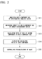
- FIG. 2 is a flow chart illustrating an example of operation of the multi-component gas analysis system in accordance with an embodiment of the present invention.
- the flow chart illustrated in Fig. 2 is, for example, performed continuously or performed repeatedly with a predetermined time interval.
- Step S11 a process of analyzing the multi-component gas G by the spectrometric analysis device 11 is performed (Step S11, first step). Specifically, a laser light is irradiated on the multi-component gas G, the laser light transmitted through the multi-component gas G is received, an absorption spectrum is obtained, and the ratio of components (methane, ethane, propane, butane, and pentane) contained in the multi-component gas G is obtained based on the obtained absorption spectrum.
- Step S12 a process of measuring the density of the multi-component gas G is performed by the density measurement device 12 (Step S12, second step).
- the process of Step S12 may be performed before the process of Step S11 or may be performed in parallel with the process of Step S11.
- a process of computing the component ratio of hydrogen and nitrogen contained in the multi-component gas G is performed by the calculation and control device 15 using the measurement results of the pressure measurement device 13 and the temperature measurement device 14 in addition to the analysis result of the spectrometric analysis device 11 and the measurement result of the density measurement device 12 (Step S13).
- the component ratio f of the mixed gas of hydrogen and nitrogen contained in the multi-component gas G is obtained from the above equation (4) using the analysis result of the spectrometric analysis device 11.
- the ratio r of hydrogen of the mixed gas of hydrogen and nitrogen that is contained in the multi-component gas G is obtained from the above equations (5) to (8) using the analysis result of the spectrometric analysis device 11 and the measurement results of the density measurement device 12, the pressure measurement device 13, and the temperature measurement device 14.
- the component ratio f(H 2 ) of hydrogen and the component ratio f(N 2 ) of nitrogen contained in the multi-component gas G is obtained respectively from the above equations (9) and (10).
- a process of displaying the computed component ratio of hydrogen and nitrogen on the display 15a is performed by the calculation and control device 15 (Step S14).
- the component ratio of methane, ethane, propane, butane, and pentane may be displayed in addition to the component ratio of hydrogen and nitrogen.
- a process of controlling the aperture of the valve V based on the component ratio of hydrogen computed at Step S13 is performed by the calculation and control device 15 if needed (Step S 15).
- the aperture of the valve V is controlled so that the mixture ratio of the natural gas G1 and the hydrogen gas G2 may not become more than a predetermined ratio (for example, 15% or more).
- the density measurement device 12 that measures the density of the multi-component gas G is provided.
- the component ratio of the component contained in the multi-component gas G is obtained using the analysis result of the spectrometric analysis device 11 and the measurement result of the density measurement device 12. Therefore, even if a plurality of components (for example, hydrogen, nitrogen, or the like) that cannot be analyzed by the spectrometric analysis device 11 are contained in the multi-component gas G, the component ratio of these components (hydrogen, nitrogen, or the like) can be measured continuously.
- components other than methane, ethane, propane, butane, and pentane contained in the multi-component gas G were hydrogen and nitrogen.
- these components are not necessarily restricted to hydrogen and nitrogen.
- These components may be diatomic molecules such as oxygen (O 2 ) and chlorine (Cl 2 ) or molecules such as carbon monoxide (CO), carbon dioxide (CO 2 ), sulfur oxide (SOx), and nitrogen oxide (NOx), in addition to hydrogen and nitrogen.
- any of a plurality of kinds of gas may be used as long as their molecular weights differ.
- the laser gas analysis meter has been described as an example of the spectrometric analysis device 11.
- the spectrometric analysis device 11 is not necessarily restricted to the laser gas analysis meter.
- FT-IR Fastier-transform-infrared-spectroscopy
- NIR near-infrared
- Raman spectrometer may be also used for the spectrometric analysis device 11.
- the gas density meter has been described as an example of the density measurement device 12.
- the density measurement device 12 is not necessarily restricted to the gas density meter.
- mass flowmeters such as Coriolis mass flowmeter and heat type mass flowmeter may also be used for the density measurement device 12.
- the term "configured” is used to describe a component, unit or part of a device includes hardware and/or software that is constructed and/or programmed to carry out the desired function.
- unit is used to describe a component, unit or part of a hardware and/or software that is constructed and/or programmed to carry out the desired function.
- Typical examples of the hardware may include, but are not limited to, a device and a circuit.
Landscapes
- Physics & Mathematics (AREA)
- Chemical & Material Sciences (AREA)
- Health & Medical Sciences (AREA)
- Life Sciences & Earth Sciences (AREA)
- General Physics & Mathematics (AREA)
- Analytical Chemistry (AREA)
- Biochemistry (AREA)
- General Health & Medical Sciences (AREA)
- Immunology (AREA)
- Pathology (AREA)
- Spectroscopy & Molecular Physics (AREA)
- Engineering & Computer Science (AREA)
- Combustion & Propulsion (AREA)
- Food Science & Technology (AREA)
- Medicinal Chemistry (AREA)
- Investigating Or Analysing Materials By Optical Means (AREA)
Abstract
Description
- The present invention relates to a multi-component gas analysis system and a multi-component gas analysis method.
- Priority is claimed on Japanese Patent Application No.
2015-105631, filed on May 25, 2015 - All patents, patent applications, patent publications, scientific articles, and the like, which will hereinafter be cited or identified in the present application, will hereby be incorporated by reference in their entirety in order to describe more fully the state of the art to which the present invention pertains.
- In general, concentration of a specific component contained in a multi-component gas is measured using a gas chromatography. The gas chromatography includes a tubular route called a column and a gas concentration detector provided at the end of the column. The multi-component gas is transmitted thorough the column. Each of the components in the multi-component gas travels through the column at a different speed and is distinguishable (separated) thereby. The concentration of each component contained in the multi-component gas is determined by measuring the amount of each separated component with the gas concentration detector.
- In addition, the concentration of the specific component contained in the multi-component gas may also be measured using a spectrometric analysis device. The spectrometric analysis device includes light source that emits light of a specific wavelength (e.g., infrared light), and a photodetector for receiving the light from the light source. In the spectrometric analysis device, the light emitted from the light source is irradiated to the multi-component gas. The light transmitted through the multi-component gas is received by the photodetector and the absorption spectrum (the spectrum of absorbance for light at each wavelength) of the received light is determined. Thereby, the concentration of each component contained in the multi-component gas is measured.
- The following patent documents disclose a conventional technology that can analyze (measure) a plurality of components contained in the multi-component gas. Specifically, Japanese Unexamined Patent Application, First Publication No.
2000-346801 2001-099781 2013-174558 - The gas chromatograph described above can perform a measurement of concentrations for a plurality of components contained in the multi-component gas with sufficient accuracy, but it takes a long time such as about several minutes to perform the measurement. Therefore, the gas chromatograph is not suitable for the use that needs to analyze continuously the component contained in the multi-component gas (for example, a management use of a process that needs to perform an adjustment of heat quantity and an observation of components contained in a combustion gas).
- On the other hand, the spectrometric analysis device described above can perform a measurement in a short time such as about several seconds. Therefore, the spectrometric analysis device can be used also for a use that needs to analyze continuously the component contained in the multi-component gas. However, the spectrometric analysis device measures the concentration of the component contained in the multi-component gas based on the absorbance of light. Therefore, the kind of components that can be measured is limited. For example, the spectrometric analysis device can measure a component that absorbs infrared light (for example, methane (CH4), ethane (C2H6), or the like), while it is difficult for the spectrometric analysis device to measure a component that does not absorb infrared light (for example, diatomic molecules, such as hydrogen (H2), oxygen (O2), nitrogen (N2), or the like).
- In addition, even in a case in which the above-described component that does not absorb infrared light is contained in the multi-component gas, it is possible to measure the ratio of the component (component ratio) using the spectrometric analysis device as long as the number of the components is one. Specifically, by measuring respectively the component ratio of each component that absorbs infrared light using the spectrometric analysis device and by deducting total of these component ratios from the whole, it is possible to obtain the component ratio of the component that does not absorb infrared light. However, when a plurality of components that do not absorb infrared light are contained in the multi-component gas, it is impossible to obtain the component ratio of each of these components.
- The present invention provides a multi-component gas analysis system and a multi-component gas analysis method that can continuously obtain a component ratio for each component contained in the multi-component gas even in a case in which a plurality of components that cannot be analyzed using the spectrometric analysis device are contained in the multi-component gas.
- A multi-component gas analysis system according to an aspect of the present invention includes: a spectrometric analysis device configured to obtain ratio of each of first components in a multi-component gas based on an absorption spectrum of light that has transmitted through the multi-component gas; a density measurement device configured to measure a first density of the multi-component gas; and a calculation device configured to calculate a ratio of each of second components in the multi-component gas using the ratio of each of the first components obtained by the spectrometric analysis device and the first density measured by the density measurement device, the second components being components that cannot be obtained by the spectrometric analysis device.
- The calculation device may be configured to calculate a second density of the multi-component gas using the ratio of each of the first components obtained by the spectrometric analysis device, and the calculation device may be configured to calculate the ratio of each of the second components by comparing the second density with the first density.
- The multi-component gas analysis system may further include: a pressure measurement device configured to measure a pressure of the multi-component gas; and a temperature measurement device configured to measure a temperature of the multi-component gas. The calculation device may be configured to calculate the ratio of each of the second components using the pressure of the multi-component gas measured by the pressure measurement device and the temperature of the multi-component gas measured by the temperature measurement device, in addition to the ratio of each of the first components obtained by the spectrometric analysis device and the first density measured by the density measurement device.
- The spectrometric analysis device may be a Fourier transform infrared spectrometric analysis meter, a near-infrared spectrometric analysis meter, a laser gas analysis meter, or a Raman spectrometer.
- The density measurement device may be a gas densimeter or a mass flowmeter.
- The first components may be components that absorb infrared light, and the second components may be components that do not absorb the infrared light.
- A multi-component gas analysis method according to an aspect of the present invention may include: a first step of acquiring , by a spectrometric analysis device, ratio of each of first components in a multi-component gas based on an absorption spectrum of light that has transmitted through the multi-component gas; a second step of measuring, by a density measurement device, a first density of the multi-component gas; and a third step of calculating ratio of each of second components in the multi-component gas using the ratio of each of the first components obtained in the first step and the first density measured in the second step, the second components being components that cannot be obtained by the spectrometric analysis device.
- The third step may include: calculating a second density of the multi-component gas using the ratio of each of the first components obtained in the first step, and comparing the second density with the first density.
- The multi-component gas analysis method may further include: measuring a pressure of the multi-component gas; and measuring a temperature of the multi-component gas. In the third step, the ratio of each of the second components may be calculated using the pressure of the multi-component gas that has been measured and the temperature of the multi-component gas that has been measured, in addition to the ratio of each of the first components obtained in the first step and the first density measured in the second step.
- The spectrometric analysis device may be a Fourier transform infrared spectrometric analysis meter, a near-infrared spectrometric analysis meter, a laser gas analysis meter, or a Raman spectrometer.
- The density measurement device may be a gas densimeter or a mass flowmeter.
- The first components may be components that absorb infrared light, and the second components may be components that do not absorb the infrared light.
- According to each aspect of the present invention, the density measurement device that measures the density of the multi-component gas is provided in addition to the spectrometric analysis device that analyzes the component ratio of each measurable component (first component) contained in the multi-component gas. Further, the component ratio of each unmeasurable component (second component) that cannot be analyzed by the spectrometric analysis device of the components contained in the multi-component gas is obtained using the analysis result of the spectrometric analysis device and the measurement result of density measurement device. Therefore, even in a case in which a plurality of components (second components) that cannot be analyzed by the spectrometric analysis device are contained in the multi-component gas, it is possible to obtain the component ratio of each component contained in the multi-component gas continuously.
- The above features and advantages of the present invention will be more apparent from the following description of certain preferred embodiments taken in conjunction with the accompanying drawings, in which:
-
Fig. 1 is a block diagram illustrating a principal part composition of the multi-component gas analysis system in accordance with an embodiment of the present invention; and -
Fig. 2 is a flow chart illustrating an example of an operation of the multi-component gas analysis system in accordance with an embodiment of the present invention. - The present invention will be now described herein with reference to illustrative preferred embodiments. Those skilled in the art will recognize that many alternative preferred embodiments can be accomplished using the teaching of the present invention and that the present invention is not limited to the preferred embodiments illustrated herein for explanatory purposes.
- Hereinafter, a multi-component gas analysis system and a multi-component gas analysis method in accordance with an embodiment of the present invention will be described in detail with reference to the drawings.
Fig. 1 is a block diagram illustrating a principal part composition of the multi-component gas analysis system in accordance with an embodiment of the present invention. As described inFig. 1 , the multi-component gas analysis system in accordance with this embodiment includes aspectrometric analysis device 11, adensity measurement device 12, apressure measurement device 13, atemperature measurement device 14, and an calculation and control device 15 (calculation device), and analyzes components contained in the multi-component gas G. - In this embodiment, to facilitate understanding, the multi-component gas G includes methane (CH4), ethane (C2H6), propane (C3H8), butane (C4H10), pentane (C5H12), hydrogen (H2), and nitrogen (N2). Below, to facilitate description, the molecular weight of methane, ethane, propane, butane, and pentane is set to "16", "30", "44", "58", and "72", respectively, and the molecular weight of hydrogen and nitrogen is set to "2" and "14", respectively.
- Here, components that absorb infrared light among the components contained in the multi-component gas are referred to as a first component, and components that do not absorb infrared light are referred to as a second component. Methane, ethane, propane, butane, and pentane are the first component. Hydrogen and nitrogen are the second component. The spectrometric analysis device can analyze the first component, while the spectrometric analysis device cannot analyze the second component.
- As illustrated in
Fig. 1 , the multi-component gas G is obtained by a gas mixing machine MX mixing a natural gas G1 including methane, ethane, propane, butane, pentane, and nitrogen with a hydrogen gas G2. The hydrogen gas G2 is obtained by decomposing water with an electric power obtained by, for example, a wind power generation. In order to use a renewable energy effectively, the hydrogen gas G2 is used by being mixed with the natural gas G1. As illustrated inFig. 1 , the valve V for adjusting the amount of supply of the hydrogen gas G2 is provided in the supply course of the hydrogen gas G2 to the gas mixing machine MX. - The
spectrometric analysis device 11 analyzes each component of methane, ethane, propane, butane, and pentane contained in the multi-component gas G based on the absorption spectrum of the light (for example, infrared light) transmitted through the multi-component gas G. Thespectrometric analysis device 11 cannot analyze components such as hydrogen and nitrogen other than methane, ethane, propane, butane, and pentane contained in the multi-component gas G, because these components (hydrogen and nitrogen) do not absorb the light transmitted through the multi-component gas G. Thespectrometric analysis device 11 is, for example, a laser gas analysis meter that measures each component contained in the multi-component gas G based on the absorption spectrum of the laser light that is irradiated on the multi-component gas G with laser light (for example, infrared laser light) and is transmitted through the multi-component gas G. - The
density measurement device 12 measures the density (mass per unit volume) of the multi-component gas G. That is, thedensity measurement device 12 measures the density of the multi-component gas G containing the component (methane, ethane, propane, butane, and pentane) that can be analyzed by thespectrometric analysis device 11 and the component (hydrogen and nitrogen) that cannot be analyzed by thespectrometric analysis device 11. Thedensity measurement device 12 is provided in order to obtain the component ratio of the component (hydrogen and nitrogen) that cannot be analyzed by thespectrometric analysis device 11. Thedensity measurement device 12 is a gas density meter, for example. - The
pressure measurement device 13 measures the pressure of the multi-component gas G. Thetemperature measurement device 14 measures the temperature of the multi-component gas G. Thepressure measurement device 13 and thetemperature measurement device 14 are provided in order to correct the density of the multi-component gas G that varies depending on the pressure and the temperature of the multi-component gas G (for example, correct the density into a value at 1 atmosphere and 0 degree C). When the pressure and the temperature of the multi-component gas G are constant and known in advance, it is possible to omit thepressure measurement device 13 andtemperature measurement device 14. - Here, the density of gas is obtained by the product of the molecularity per unit volume (the number of Mol) and the molecular weight. The molecularity n per unit volume is generally expressed as the following formula using the gaseous pressure p, the temperature (absolute temperature) T, and the gas constant R.

- As shown by the above formula, the molecularity n per unit volume (namely, density of gas) changes based on the gaseous pressure p and the temperature T. The
pressure measurement device 13 and thetemperature measurement device 14 are provided in order to correct this change. - The calculation and
control device 15 obtains the component ratio of the component (hydrogen and nitrogen), which cannot be analyzed by thespectrometric analysis device 11, among the components contained in the multi-component gas G using the analysis result of thespectrometric analysis device 11 and the measurement result of thedensity measurement device 12. Specifically, the calculation andcontrol device 15 compares the density of the multi-component gas G computed using the analysis result of thespectrometric analysis device 11 with the density measured by thedensity measurement device 12, and obtains the component ratio of hydrogen and nitrogen contained in the multi-component gas G. When thepressure measurement device 13 and thetemperature measurement device 14 are provided, the calculation andcontrol device 15 obtains the component ratio of hydrogen and nitrogen further using the measurement results of thepressure measurement device 13 and thetemperature measurement device 14. - Here, a, b, c, d, and e represent the component ratio of methane, ethane, propane, butane, and pentane, which are contained in the multi-component gas G, respectively. Also, r represents the ratio of hydrogen among the component (hydrogen and nitrogen) in the multi-component gas G except methane, ethane, propane, butane, and pentane. The density p of the multi-component gas G is expressed by the following equation (1).

- Here, ρ1 at the right side of the above equation (1) represents the density of methane, ethane, propane, butane, and pentane and is expressed by the following equation (2). Also, p2 of the right side of the above equation (1) represents the density of hydrogen and nitrogen and is expressed by the following equation (3). In addition, k in the following equations (2) and (3) represents a constant that is determined by the pressure and temperature of the multi-component gas G.


- The component ratios (the variables a, b, c, d, and e in the above equations (2) and (3)) of methane, ethane, propane, butane, and pentane, which are contained in the multi-component gas G, are obtained from the analysis result of the
spectrometric analysis device 11. The calculation andcontrol device 15 compares the density ρ of the multi-component gas G, which is calculated from the above equations (1) to (3) using the analytical result of thespectroscopic analysis device 11, with the density of the multi-component gas G to be measured by thedensity measuring device 12, determines the ratio of hydrogen and nitrogen (variable r in the above equation (3)), and finally obtains the component ratio of hydrogen and nitrogen contained in the multicomponent gas G. - Specifically, the calculation and
control device 15 obtains the component ratio of hydrogen contained in the multi-component gas G using a method described below. If the component ratio of hydrogen contained in the multi-component gas G is obtained, the component ratio of nitrogen contained in the multi-component gas G will also be obtained. First, the calculation andcontrol device 15 obtains the component ratio f of the mixed gas of hydrogen and nitrogen contained in the multi-component gas G from the following equation (4) using the analysis result of thespectrometric analysis device 11.
- Next, the calculation and
control device 15 calculates the molecular weight M of the multi-component gas G from the following equations (5) and (6) using the measurement results of thedensity measurement device 12, thepressure measurement device 13, and thetemperature measurement device 14.

- Here, the above equation (5) calculates the density ρ0 of the multi-component gas G at 1 atmosphere and 0 degree C. ρ in the above equation (5) represents the density of the multi-component gas G to be measured by the
density measuring device 12. P represents the pressure of the multi-component gas G to be measured by thepressure measurement device 13. T represents the temperature (absolute temperature) of the multi-component gas G to be measured by thetemperature measurement device 14. - Next, the calculation and
control device 15 calculates the average molecular weight Ma of the mixed gas of hydrogen and nitrogen, which are contained in the multi-component gas G, from the following equation (7) using the analysis result of thespectrometric analysis device 11, the component ratio f of the mixed gas of hydrogen and nitrogen obtained from the above equation (4), and the molecular weight M of the multi-component gas G obtained from the above equation (6).
- Then, the calculation and
control device 15 obtains the ratio r of hydrogen contained in the above mixed gas from the following equation (8) using the average molecular weight Ma of the mixed gas of hydrogen and nitrogen that is obtained from the above equation (7).

- Finally, the calculation and
control device 15 obtains the component ratio f(H2) of hydrogen contained in the multi-component gas G from the following equation (9) using the component ratio f of the mixed gas of hydrogen and nitrogen obtained from the above equation (4) and the ratio r of hydrogen contained in the mixed gas obtained from the above equation (8).
- In addition, the calculation and
control device 15 obtains the component ratio f (N2) of nitrogen contained in the multi-component gas G from the following equation (10).
- Moreover, the calculation and
control device 15 displays the obtained component ratio of hydrogen and nitrogen on adisplay 15a equipped with a display device such as a liquid crystal display device. In addition to the component ratio of hydrogen and nitrogen, the component ratio of methane, ethane, propane, butane, and pentane may be displayed on thedisplay 15a. Also, the calculation andcontrol device 15 controls the aperture of the valve V based on the obtained component ratio of hydrogen. For example, the calculation andcontrol device 15 controls the aperture of the valve V so that the mixture ratio of the natural gas G1 and the hydrogen gas G2 does not become more than a predetermined ratio (for example, 15% or more). - Next, operation of the multi-component gas analysis system 1 of the above-described composition will be described.
Fig. 2 is a flow chart illustrating an example of operation of the multi-component gas analysis system in accordance with an embodiment of the present invention. Here, the flow chart illustrated inFig. 2 is, for example, performed continuously or performed repeatedly with a predetermined time interval. - When processing of the flow chart illustrated in
Fig. 2 is started, a process of analyzing the multi-component gas G by thespectrometric analysis device 11 is performed (Step S11, first step). Specifically, a laser light is irradiated on the multi-component gas G, the laser light transmitted through the multi-component gas G is received, an absorption spectrum is obtained, and the ratio of components (methane, ethane, propane, butane, and pentane) contained in the multi-component gas G is obtained based on the obtained absorption spectrum. - Next, a process of measuring the density of the multi-component gas G is performed by the density measurement device 12 (Step S12, second step). Here, the process of Step S12 may be performed before the process of Step S11 or may be performed in parallel with the process of Step S11. Then, a process of computing the component ratio of hydrogen and nitrogen contained in the multi-component gas G is performed by the calculation and
control device 15 using the measurement results of thepressure measurement device 13 and thetemperature measurement device 14 in addition to the analysis result of thespectrometric analysis device 11 and the measurement result of the density measurement device 12 (Step S13). - Specifically, first, the component ratio f of the mixed gas of hydrogen and nitrogen contained in the multi-component gas G is obtained from the above equation (4) using the analysis result of the
spectrometric analysis device 11. Next, the ratio r of hydrogen of the mixed gas of hydrogen and nitrogen that is contained in the multi-component gas G is obtained from the above equations (5) to (8) using the analysis result of thespectrometric analysis device 11 and the measurement results of thedensity measurement device 12, thepressure measurement device 13, and thetemperature measurement device 14. At the end, the component ratio f(H2) of hydrogen and the component ratio f(N2) of nitrogen contained in the multi-component gas G is obtained respectively from the above equations (9) and (10). - When the above processing ends, a process of displaying the computed component ratio of hydrogen and nitrogen on the
display 15a is performed by the calculation and control device 15 (Step S14). Here, the component ratio of methane, ethane, propane, butane, and pentane may be displayed in addition to the component ratio of hydrogen and nitrogen. Also, a process of controlling the aperture of the valve V based on the component ratio of hydrogen computed at Step S13 is performed by the calculation andcontrol device 15 if needed (Step S 15). For example, the aperture of the valve V is controlled so that the mixture ratio of the natural gas G1 and the hydrogen gas G2 may not become more than a predetermined ratio (for example, 15% or more). - As described above, in this embodiment, in addition to the
spectrometric analysis device 11 that analyzes the components contained in the multi-component gas G based on the absorption spectrum of the light transmitted through the multi-component gas G, thedensity measurement device 12 that measures the density of the multi-component gas G is provided. The component ratio of the component contained in the multi-component gas G is obtained using the analysis result of thespectrometric analysis device 11 and the measurement result of thedensity measurement device 12. Therefore, even if a plurality of components (for example, hydrogen, nitrogen, or the like) that cannot be analyzed by thespectrometric analysis device 11 are contained in the multi-component gas G, the component ratio of these components (hydrogen, nitrogen, or the like) can be measured continuously. - As described above, although the multi-component gas analysis system and the multi-component gas analysis method in accordance with an embodiment of the present invention have been described, the present invention can be freely changed within the limits of the present invention without being restricted to the above-described embodiment. For example, in the above-described embodiment, components other than methane, ethane, propane, butane, and pentane contained in the multi-component gas G were hydrogen and nitrogen. However, these components are not necessarily restricted to hydrogen and nitrogen. These components may be diatomic molecules such as oxygen (O2) and chlorine (Cl2) or molecules such as carbon monoxide (CO), carbon dioxide (CO2), sulfur oxide (SOx), and nitrogen oxide (NOx), in addition to hydrogen and nitrogen. Namely, any of a plurality of kinds of gas may be used as long as their molecular weights differ.
- Moreover, in the above-described embodiment, the laser gas analysis meter has been described as an example of the
spectrometric analysis device 11. However, thespectrometric analysis device 11 is not necessarily restricted to the laser gas analysis meter. For example, FT-IR (Fourier-transform-infrared-spectroscopy) analysis meter, NIR (near-infrared) reflectance meter, or Raman spectrometer may be also used for thespectrometric analysis device 11. - Moreover, in the above-described embodiment, the gas density meter has been described as an example of the
density measurement device 12. However, thedensity measurement device 12 is not necessarily restricted to the gas density meter. For example, mass flowmeters such as Coriolis mass flowmeter and heat type mass flowmeter may also be used for thedensity measurement device 12. - As used herein, the following directional terms "forward, rearward, above, downward, right, left, vertical, horizontal, below, transverse, row and column" as well as any other similar directional terms refer to those directions of an apparatus equipped with the present invention. Accordingly, these terms, as utilized to describe the present invention should be interpreted relative to an apparatus equipped with the present invention.
- The term "configured" is used to describe a component, unit or part of a device includes hardware and/or software that is constructed and/or programmed to carry out the desired function.
- Moreover, terms that are expressed as "means-plus function" in the claims should include any structure that can be utilized to carry out the function of that part of the present invention.
- The term "unit" is used to describe a component, unit or part of a hardware and/or software that is constructed and/or programmed to carry out the desired function. Typical examples of the hardware may include, but are not limited to, a device and a circuit.
- While preferred embodiments of the present invention have been described and illustrated above, it should be understood that these are examples of the present invention and are not to be considered as limiting. Additions, omissions, substitutions, and other modifications can be made without departing from the scope of the present invention. Accordingly, the present invention is not to be considered as being limited by the foregoing description, and is only limited by the scope of the claims.
Claims (12)
- A multi-component gas analysis system comprising:a spectrometric analysis device configured to obtain ratio of each of first components in a multi-component gas based on an absorption spectrum of light that has transmitted through the multi-component gas;a density measurement device configured to measure a first density of the multi-component gas; anda calculation device configured to calculate a ratio of each of second components in the multi-component gas using the ratio of each of the first components obtained by the spectrometric analysis device and the first density measured by the density measurement device, the second components being components that cannot be obtained by the spectrometric analysis device.
- The multi-component gas analysis system according to claim 1, wherein
the calculation device is configured to calculate a second density of the multi-component gas using the ratio of each of the first components obtained by the spectrometric analysis device, and
the calculation device is configured to calculate the ratio of each of the second components by comparing the second density with the first density. - The multi-component gas analysis system according to claim 1 or 2, further comprising:a pressure measurement device configured to measure a pressure of the multi-component gas; anda temperature measurement device configured to measure a temperature of the multi-component gas, whereinthe calculation device is configured to calculate the ratio of each of the second components using the pressure of the multi-component gas measured by the pressure measurement device and the temperature of the multi-component gas measured by the temperature measurement device, in addition to the ratio of each of the first components obtained by the spectrometric analysis device and the first density measured by the density measurement device.
- The multi-component gas analysis system according to any one of claims 1 to 3, wherein the spectrometric analysis device is a Fourier transform infrared spectrometric analysis meter, a near-infrared spectrometric analysis meter, a laser gas analysis meter, or a Raman spectrometer.
- The multi-component gas analysis system according to any one of claims 1 to 4, wherein the density measurement device is a gas densimeter or a mass flowmeter.
- The multi-component gas analysis system according to any one of claims 1 to 5, wherein the first components are components that absorb infrared light, and the second components are components that do not absorb the infrared light.
- A multi-component gas analysis method comprising:a first step of acquiring , by a spectrometric analysis device, ratio of each of first components in a multi-component gas based on an absorption spectrum of light that has transmitted through the multi-component gas;a second step of measuring, by a density measurement device, a first density of the multi-component gas; anda third step of calculating ratio of each of second components in the multi-component gas using the ratio of each of the first components obtained in the first step and the first density measured in the second step, the second components being components that cannot be obtained by the spectrometric analysis device.
- The multi-component gas analysis method according to claim 7, wherein the third step comprises:calculating a second density of the multi-component gas using the ratio of each of the first components obtained in the first step, andcomparing the second density with the first density.
- The multi-component gas analysis method according to claim 7 or 8, further comprising:measuring a pressure of the multi-component gas; andmeasuring a temperature of the multi-component gas, whereinin the third step, the ratio of each of the second components is calculated using the pressure of the multi-component gas that has been measured and the temperature of the multi-component gas that has been measured, in addition to the ratio of each of the first components obtained in the first step and the first density measured in the second step.
- The multi-component gas analysis method according to any one of claims 7 to 9, wherein the spectrometric analysis device is a Fourier transform infrared spectrometric analysis meter, a near-infrared spectrometric analysis meter, a laser gas analysis meter, or a Raman spectrometer.
- The multi-component gas analysis method according to any one of claims 7 to 10, wherein the density measurement device is a gas densimeter or a mass flowmeter.
- The multi-component gas analysis method according to any one of claims 7 to 11, wherein the first components are components that absorb infrared light, and the second components are components that do not absorb the infrared light.
Applications Claiming Priority (1)
| Application Number | Priority Date | Filing Date | Title |
|---|---|---|---|
| JP2015105631A JP6269576B2 (en) | 2015-05-25 | 2015-05-25 | Multi-component gas analysis system and method |
Publications (2)
| Publication Number | Publication Date |
|---|---|
| EP3098592A1 true EP3098592A1 (en) | 2016-11-30 |
| EP3098592B1 EP3098592B1 (en) | 2022-08-24 |
Family
ID=56026677
Family Applications (1)
| Application Number | Title | Priority Date | Filing Date |
|---|---|---|---|
| EP16170116.4A Active EP3098592B1 (en) | 2015-05-25 | 2016-05-18 | Multi-component gas analysis system and multi-component gas analysis method |
Country Status (3)
| Country | Link |
|---|---|
| US (1) | US10605724B2 (en) |
| EP (1) | EP3098592B1 (en) |
| JP (1) | JP6269576B2 (en) |
Cited By (1)
| Publication number | Priority date | Publication date | Assignee | Title |
|---|---|---|---|---|
| EP4169607A1 (en) * | 2021-10-21 | 2023-04-26 | Mems Ag | Determination of the proportions when mixing gases |
Families Citing this family (8)
| Publication number | Priority date | Publication date | Assignee | Title |
|---|---|---|---|---|
| WO2016014053A1 (en) * | 2014-07-23 | 2016-01-28 | Halliburton Energy Services, Inc. | Thermal modulated vibrating sensing module for gas molecular weight detection |
| CN109254113B (en) * | 2017-07-12 | 2021-02-05 | 中国石油化工股份有限公司 | Method and system for measuring adsorption capacity of multi-component mixed gas in gas-solid adsorption process |
| KR101907890B1 (en) | 2017-08-24 | 2018-12-18 | 한국표준과학연구원 | CRDS design method using mode matching and time-resolved coupling efficiency |
| CN108982401B (en) * | 2018-07-19 | 2020-08-25 | 西安博研仪器分析应用科技有限公司 | Method for analyzing single component flow from infrared absorption spectrum of mixed gas |
| EP3623806B1 (en) * | 2018-08-17 | 2023-06-14 | HORIBA, Ltd. | Gas analysis apparatus and gas analysis method |
| CN110907386A (en) * | 2019-11-28 | 2020-03-24 | 光钙(上海)高科技有限公司 | Multi-component gas analysis system and method for waste incineration power plant |
| CN112730546B (en) * | 2020-12-28 | 2022-09-13 | 武汉理工大学 | Portable flue gas analysis device |
| CN121039479A (en) | 2023-03-21 | 2025-11-28 | 特拉法格股份公司 | Method and apparatus for measuring gas concentration in a reaction chamber |
Citations (7)
| Publication number | Priority date | Publication date | Assignee | Title |
|---|---|---|---|---|
| DE19921167A1 (en) * | 1999-02-24 | 2000-08-31 | Ruhrgas Ag | Method and arrangement for measuring the calorific value and / or the Wobbe index of fuel gas, in particular natural gas |
| JP2000346801A (en) | 1999-06-04 | 2000-12-15 | Horiba Ltd | Multi-component gas analysis with ftir method |
| JP2001099781A (en) | 1999-09-29 | 2001-04-13 | Horiba Ltd | Method for correcting effect of co-existing gas in gas analysis by infrared absorption method |
| EP1193488A1 (en) * | 2000-09-29 | 2002-04-03 | Ruhrgas Aktiengesellschaft | Method and device for determining the gaseous quality of natural gas |
| DE102005005727A1 (en) * | 2005-02-09 | 2006-08-17 | Hans Walter Dipl.-Ing. Kirchner | Fuel gas composition and properties determining method involves determining non-infrared-active nitrogen proportion of gases as difference of measured overall pressure of gas mixture and sum of determined partial pressure of gas component |
| DE102008029553B3 (en) * | 2008-06-21 | 2009-11-26 | Elster Gmbh | Method for determining the gas quality of a sample gas at least partially mixed with biogas or treated biogas |
| JP2013174558A (en) | 2012-02-27 | 2013-09-05 | Nippon Steel & Sumitomo Metal | Multicomponent gas measurement system and measurement method |
Family Cites Families (20)
| Publication number | Priority date | Publication date | Assignee | Title |
|---|---|---|---|---|
| US4163382A (en) * | 1978-04-28 | 1979-08-07 | The United States Of America As Represented By The United States Department Of Energy | Method and apparatus for optoacoustic spectroscopy |
| US5127264A (en) * | 1991-05-20 | 1992-07-07 | Thermal Surveys, Inc. | Methods of infrared visualization of air flow |
| FI96993C (en) * | 1992-01-30 | 1996-09-25 | Vaisala Oy | Calibration procedure for gas content measurement |
| JPH0650967A (en) * | 1992-07-30 | 1994-02-25 | Tokyo Gas Co Ltd | Measuring method of nitrogen component in city gas |
| US6138497A (en) * | 1994-10-17 | 2000-10-31 | The Coca-Cola Company | Method and apparatus for simultaneously measuring CO2, O2 and N2 dissolved in liquid |
| FR2776776B1 (en) * | 1998-03-24 | 2000-04-28 | Schlumberger Ind Sa | DEVICE AND METHOD FOR DIRECT MEASUREMENT OF THE CALORIFIC ENERGY CONTAINED IN A FUEL GAS |
| GB0002535D0 (en) * | 2000-02-04 | 2000-03-29 | Bg Intellectual Pty Ltd | A method for determining the safety of gas mixtures |
| US7398160B2 (en) * | 2004-06-30 | 2008-07-08 | Southwest Research Institute | Gas energy meter for inferential determination of thermophysical properties of a gas mixture at multiple states of the gas |
| JP2006300569A (en) * | 2005-04-15 | 2006-11-02 | Nagaoka Univ Of Technology | Apparatus and method for evaluating hydrogen storage material |
| US7653497B2 (en) * | 2007-05-15 | 2010-01-26 | Spectrasensors, Inc. | Energy flow measurement in gas pipelines |
| JP5654343B2 (en) * | 2007-06-15 | 2015-01-14 | ビーピー ケミカルズ リミテッドBp Chemicals Limited | Online analysis method for gas-phase process flow |
| US7655925B2 (en) * | 2007-08-31 | 2010-02-02 | Cymer, Inc. | Gas management system for a laser-produced-plasma EUV light source |
| US8574798B2 (en) * | 2008-02-26 | 2013-11-05 | Fuji Xerox Co., Ltd. | Electrophotographic photoreceptor, and image forming apparatus and process cartridge using the same |
| JP2010203855A (en) * | 2009-03-02 | 2010-09-16 | Taiyo Nippon Sanso Corp | Fluorine concentration measuring method |
| JP5479949B2 (en) * | 2009-04-08 | 2014-04-23 | 株式会社東芝 | Measuring device, measuring method, and carbon dioxide recovery system |
| CN201637443U (en) * | 2009-11-07 | 2010-11-17 | 兰州海默科技股份有限公司 | Measuring device for multi-phase flow with extremely-high water content |
| US8907286B2 (en) * | 2010-04-12 | 2014-12-09 | President And Fellows Of Harvard College | Gas phase cooling and mixture analysis |
| US20140107943A1 (en) * | 2012-10-17 | 2014-04-17 | Milton Roy Company | Gas intensity calibration method and system |
| BR112016020156A2 (en) * | 2014-05-08 | 2018-05-08 | Halliburton Energy Services Inc | and methods for fabricating and forming a thin optical film device |
| US10151738B2 (en) * | 2014-12-04 | 2018-12-11 | Schlumberger Technology Corporation | Methods and apparatus for the downhole analysis of the composition of formation gases |
-
2015
- 2015-05-25 JP JP2015105631A patent/JP6269576B2/en active Active
-
2016
- 2016-05-18 EP EP16170116.4A patent/EP3098592B1/en active Active
- 2016-05-23 US US15/161,359 patent/US10605724B2/en active Active
Patent Citations (7)
| Publication number | Priority date | Publication date | Assignee | Title |
|---|---|---|---|---|
| DE19921167A1 (en) * | 1999-02-24 | 2000-08-31 | Ruhrgas Ag | Method and arrangement for measuring the calorific value and / or the Wobbe index of fuel gas, in particular natural gas |
| JP2000346801A (en) | 1999-06-04 | 2000-12-15 | Horiba Ltd | Multi-component gas analysis with ftir method |
| JP2001099781A (en) | 1999-09-29 | 2001-04-13 | Horiba Ltd | Method for correcting effect of co-existing gas in gas analysis by infrared absorption method |
| EP1193488A1 (en) * | 2000-09-29 | 2002-04-03 | Ruhrgas Aktiengesellschaft | Method and device for determining the gaseous quality of natural gas |
| DE102005005727A1 (en) * | 2005-02-09 | 2006-08-17 | Hans Walter Dipl.-Ing. Kirchner | Fuel gas composition and properties determining method involves determining non-infrared-active nitrogen proportion of gases as difference of measured overall pressure of gas mixture and sum of determined partial pressure of gas component |
| DE102008029553B3 (en) * | 2008-06-21 | 2009-11-26 | Elster Gmbh | Method for determining the gas quality of a sample gas at least partially mixed with biogas or treated biogas |
| JP2013174558A (en) | 2012-02-27 | 2013-09-05 | Nippon Steel & Sumitomo Metal | Multicomponent gas measurement system and measurement method |
Cited By (1)
| Publication number | Priority date | Publication date | Assignee | Title |
|---|---|---|---|---|
| EP4169607A1 (en) * | 2021-10-21 | 2023-04-26 | Mems Ag | Determination of the proportions when mixing gases |
Also Published As
| Publication number | Publication date |
|---|---|
| US20160349176A1 (en) | 2016-12-01 |
| US10605724B2 (en) | 2020-03-31 |
| JP2016217985A (en) | 2016-12-22 |
| JP6269576B2 (en) | 2018-01-31 |
| EP3098592B1 (en) | 2022-08-24 |
Similar Documents
| Publication | Publication Date | Title |
|---|---|---|
| EP3098592B1 (en) | Multi-component gas analysis system and multi-component gas analysis method | |
| US10495570B2 (en) | Measurement of hydrocarbon fuel gas composition and properties from tunable diode laser absorption spectrometry | |
| TWI453397B (en) | Method and apparatus for background compensation by multiple-peak measurements for absorption spectroscopy-based gas sensing | |
| EP3218695B1 (en) | Target analyte detection and quantification in sample gases with complex background compositions | |
| CN104713841B (en) | Self-calibration analyzer design method and device | |
| Wang et al. | Multi-component gas measurement aliasing spectral demodulation method for interference separation in laser absorption spectroscopy | |
| Smith | The benzene fingers, part I: Overtone and combination bands | |
| CN104374712A (en) | Spectral pattern change compensation method and spectral pattern change compensation device for spectrum analyzer | |
| Nguyen et al. | Line-shape parameters and their temperature dependences predicted from molecular dynamics simulations for O2-and air-broadened CO2 lines | |
| Gao et al. | An adaptive absorption spectroscopy with adjustable moving window width for suppressing nonlinear effects in absorbance measurements | |
| Le et al. | Isolated line shape of methane with various collision partners | |
| Gao et al. | Dual-gas sensor for ultra-close overlapping spectra based on second harmonic peak shift | |
| Xu et al. | TDLAS based gas absorption spectrum detection system for the college physics experimental teaching | |
| Puxty et al. | IR monitoring of absorbent composition and degradation during pilot plant operation | |
| Kiseleva et al. | Line strength measurements and relative isotopic ratio 13C/12C measurements in carbon dioxide using cavity ring down spectroscopy | |
| Végh et al. | Compensation of composition variation-induced sensitivity changes in gas phase photoacoustics | |
| Tang et al. | Measurements of CH3D line strengths, foreign pressure-broadening, and pressure-shift coefficients at near-IR region using continuous-wave cavity ring-down spectroscopy | |
| Domanskaya et al. | Intensities in the composite infrared spectrum of SF6 in mixtures with air at 296 K | |
| Mooij et al. | Precision spectroscopy of the A 2Π← X 2Σ+ transition in BaF | |
| EP4296652A1 (en) | Enhancements to laser spectroscopy modeling by measurement of hydrocarbon fuel gas compositions | |
| CA2965728C (en) | Method for determining the origin of a mixture of constituents by spectral analysis | |
| Stephenson et al. | Continuous online Fourier transform infrared (FT-IR) spectrometry analysis of hydrogen chloride (HCl), carbon dioxide (CO2), and water (H2O) in nitrogen-rich and ethylene-rich streams | |
| EP4394356A1 (en) | Quantification of target analytes based on multi-layer multi-variant spectra analysis for spectroscopic analyzers | |
| Jakubowski et al. | Comparison of Peristaltic Pumps Used for Sample Introduction in Inductively Coupled Plasma–Atomic Emission Spectroscopy (ICP-AES) | |
| Ali et al. | Measurement of gas concentrations (O2, CO2, N2O and volatile agents) |
Legal Events
| Date | Code | Title | Description |
|---|---|---|---|
| PUAI | Public reference made under article 153(3) epc to a published international application that has entered the european phase |
Free format text: ORIGINAL CODE: 0009012 |
|
| AK | Designated contracting states |
Kind code of ref document: A1 Designated state(s): AL AT BE BG CH CY CZ DE DK EE ES FI FR GB GR HR HU IE IS IT LI LT LU LV MC MK MT NL NO PL PT RO RS SE SI SK SM TR |
|
| AX | Request for extension of the european patent |
Extension state: BA ME |
|
| STAA | Information on the status of an ep patent application or granted ep patent |
Free format text: STATUS: REQUEST FOR EXAMINATION WAS MADE |
|
| 17P | Request for examination filed |
Effective date: 20170529 |
|
| RBV | Designated contracting states (corrected) |
Designated state(s): AL AT BE BG CH CY CZ DE DK EE ES FI FR GB GR HR HU IE IS IT LI LT LU LV MC MK MT NL NO PL PT RO RS SE SI SK SM TR |
|
| STAA | Information on the status of an ep patent application or granted ep patent |
Free format text: STATUS: EXAMINATION IS IN PROGRESS |
|
| 17Q | First examination report despatched |
Effective date: 20200814 |
|
| GRAP | Despatch of communication of intention to grant a patent |
Free format text: ORIGINAL CODE: EPIDOSNIGR1 |
|
| STAA | Information on the status of an ep patent application or granted ep patent |
Free format text: STATUS: GRANT OF PATENT IS INTENDED |
|
| RIC1 | Information provided on ipc code assigned before grant |
Ipc: G01N 21/3504 20140101ALN20220204BHEP Ipc: F23K 5/00 20060101ALN20220204BHEP Ipc: G01N 33/00 20060101ALI20220204BHEP Ipc: G01N 33/22 20060101ALI20220204BHEP Ipc: G01N 21/85 20060101AFI20220204BHEP |
|
| INTG | Intention to grant announced |
Effective date: 20220310 |
|
| GRAS | Grant fee paid |
Free format text: ORIGINAL CODE: EPIDOSNIGR3 |
|
| GRAA | (expected) grant |
Free format text: ORIGINAL CODE: 0009210 |
|
| STAA | Information on the status of an ep patent application or granted ep patent |
Free format text: STATUS: THE PATENT HAS BEEN GRANTED |
|
| AK | Designated contracting states |
Kind code of ref document: B1 Designated state(s): AL AT BE BG CH CY CZ DE DK EE ES FI FR GB GR HR HU IE IS IT LI LT LU LV MC MK MT NL NO PL PT RO RS SE SI SK SM TR |
|
| REG | Reference to a national code |
Ref country code: CH Ref legal event code: EP |
|
| REG | Reference to a national code |
Ref country code: IE Ref legal event code: FG4D |
|
| REG | Reference to a national code |
Ref country code: AT Ref legal event code: REF Ref document number: 1513988 Country of ref document: AT Kind code of ref document: T Effective date: 20220915 Ref country code: DE Ref legal event code: R096 Ref document number: 602016074444 Country of ref document: DE |
|
| REG | Reference to a national code |
Ref country code: LT Ref legal event code: MG9D |
|
| REG | Reference to a national code |
Ref country code: NL Ref legal event code: MP Effective date: 20220824 |
|
| PG25 | Lapsed in a contracting state [announced via postgrant information from national office to epo] |
Ref country code: SE Free format text: LAPSE BECAUSE OF FAILURE TO SUBMIT A TRANSLATION OF THE DESCRIPTION OR TO PAY THE FEE WITHIN THE PRESCRIBED TIME-LIMIT Effective date: 20220824 Ref country code: RS Free format text: LAPSE BECAUSE OF FAILURE TO SUBMIT A TRANSLATION OF THE DESCRIPTION OR TO PAY THE FEE WITHIN THE PRESCRIBED TIME-LIMIT Effective date: 20220824 Ref country code: PT Free format text: LAPSE BECAUSE OF FAILURE TO SUBMIT A TRANSLATION OF THE DESCRIPTION OR TO PAY THE FEE WITHIN THE PRESCRIBED TIME-LIMIT Effective date: 20221226 Ref country code: NO Free format text: LAPSE BECAUSE OF FAILURE TO SUBMIT A TRANSLATION OF THE DESCRIPTION OR TO PAY THE FEE WITHIN THE PRESCRIBED TIME-LIMIT Effective date: 20221124 Ref country code: NL Free format text: LAPSE BECAUSE OF FAILURE TO SUBMIT A TRANSLATION OF THE DESCRIPTION OR TO PAY THE FEE WITHIN THE PRESCRIBED TIME-LIMIT Effective date: 20220824 Ref country code: LV Free format text: LAPSE BECAUSE OF FAILURE TO SUBMIT A TRANSLATION OF THE DESCRIPTION OR TO PAY THE FEE WITHIN THE PRESCRIBED TIME-LIMIT Effective date: 20220824 Ref country code: LT Free format text: LAPSE BECAUSE OF FAILURE TO SUBMIT A TRANSLATION OF THE DESCRIPTION OR TO PAY THE FEE WITHIN THE PRESCRIBED TIME-LIMIT Effective date: 20220824 Ref country code: FI Free format text: LAPSE BECAUSE OF FAILURE TO SUBMIT A TRANSLATION OF THE DESCRIPTION OR TO PAY THE FEE WITHIN THE PRESCRIBED TIME-LIMIT Effective date: 20220824 Ref country code: ES Free format text: LAPSE BECAUSE OF FAILURE TO SUBMIT A TRANSLATION OF THE DESCRIPTION OR TO PAY THE FEE WITHIN THE PRESCRIBED TIME-LIMIT Effective date: 20220824 |
|
| REG | Reference to a national code |
Ref country code: AT Ref legal event code: MK05 Ref document number: 1513988 Country of ref document: AT Kind code of ref document: T Effective date: 20220824 |
|
| PG25 | Lapsed in a contracting state [announced via postgrant information from national office to epo] |
Ref country code: PL Free format text: LAPSE BECAUSE OF FAILURE TO SUBMIT A TRANSLATION OF THE DESCRIPTION OR TO PAY THE FEE WITHIN THE PRESCRIBED TIME-LIMIT Effective date: 20220824 Ref country code: IS Free format text: LAPSE BECAUSE OF FAILURE TO SUBMIT A TRANSLATION OF THE DESCRIPTION OR TO PAY THE FEE WITHIN THE PRESCRIBED TIME-LIMIT Effective date: 20221224 Ref country code: HR Free format text: LAPSE BECAUSE OF FAILURE TO SUBMIT A TRANSLATION OF THE DESCRIPTION OR TO PAY THE FEE WITHIN THE PRESCRIBED TIME-LIMIT Effective date: 20220824 Ref country code: GR Free format text: LAPSE BECAUSE OF FAILURE TO SUBMIT A TRANSLATION OF THE DESCRIPTION OR TO PAY THE FEE WITHIN THE PRESCRIBED TIME-LIMIT Effective date: 20221125 |
|
| REG | Reference to a national code |
Ref country code: FR Ref legal event code: PLFP Year of fee payment: 8 |
|
| PG25 | Lapsed in a contracting state [announced via postgrant information from national office to epo] |
Ref country code: SM Free format text: LAPSE BECAUSE OF FAILURE TO SUBMIT A TRANSLATION OF THE DESCRIPTION OR TO PAY THE FEE WITHIN THE PRESCRIBED TIME-LIMIT Effective date: 20220824 Ref country code: RO Free format text: LAPSE BECAUSE OF FAILURE TO SUBMIT A TRANSLATION OF THE DESCRIPTION OR TO PAY THE FEE WITHIN THE PRESCRIBED TIME-LIMIT Effective date: 20220824 Ref country code: DK Free format text: LAPSE BECAUSE OF FAILURE TO SUBMIT A TRANSLATION OF THE DESCRIPTION OR TO PAY THE FEE WITHIN THE PRESCRIBED TIME-LIMIT Effective date: 20220824 Ref country code: CZ Free format text: LAPSE BECAUSE OF FAILURE TO SUBMIT A TRANSLATION OF THE DESCRIPTION OR TO PAY THE FEE WITHIN THE PRESCRIBED TIME-LIMIT Effective date: 20220824 Ref country code: AT Free format text: LAPSE BECAUSE OF FAILURE TO SUBMIT A TRANSLATION OF THE DESCRIPTION OR TO PAY THE FEE WITHIN THE PRESCRIBED TIME-LIMIT Effective date: 20220824 |
|
| REG | Reference to a national code |
Ref country code: DE Ref legal event code: R097 Ref document number: 602016074444 Country of ref document: DE |
|
| PG25 | Lapsed in a contracting state [announced via postgrant information from national office to epo] |
Ref country code: SK Free format text: LAPSE BECAUSE OF FAILURE TO SUBMIT A TRANSLATION OF THE DESCRIPTION OR TO PAY THE FEE WITHIN THE PRESCRIBED TIME-LIMIT Effective date: 20220824 Ref country code: EE Free format text: LAPSE BECAUSE OF FAILURE TO SUBMIT A TRANSLATION OF THE DESCRIPTION OR TO PAY THE FEE WITHIN THE PRESCRIBED TIME-LIMIT Effective date: 20220824 |
|
| PG25 | Lapsed in a contracting state [announced via postgrant information from national office to epo] |
Ref country code: AL Free format text: LAPSE BECAUSE OF FAILURE TO SUBMIT A TRANSLATION OF THE DESCRIPTION OR TO PAY THE FEE WITHIN THE PRESCRIBED TIME-LIMIT Effective date: 20220824 |
|
| PLBE | No opposition filed within time limit |
Free format text: ORIGINAL CODE: 0009261 |
|
| STAA | Information on the status of an ep patent application or granted ep patent |
Free format text: STATUS: NO OPPOSITION FILED WITHIN TIME LIMIT |
|
| P01 | Opt-out of the competence of the unified patent court (upc) registered |
Effective date: 20230603 |
|
| 26N | No opposition filed |
Effective date: 20230525 |
|
| PG25 | Lapsed in a contracting state [announced via postgrant information from national office to epo] |
Ref country code: SI Free format text: LAPSE BECAUSE OF FAILURE TO SUBMIT A TRANSLATION OF THE DESCRIPTION OR TO PAY THE FEE WITHIN THE PRESCRIBED TIME-LIMIT Effective date: 20220824 |
|
| REG | Reference to a national code |
Ref country code: CH Ref legal event code: PL |
|
| PG25 | Lapsed in a contracting state [announced via postgrant information from national office to epo] |
Ref country code: MC Free format text: LAPSE BECAUSE OF FAILURE TO SUBMIT A TRANSLATION OF THE DESCRIPTION OR TO PAY THE FEE WITHIN THE PRESCRIBED TIME-LIMIT Effective date: 20220824 |
|
| REG | Reference to a national code |
Ref country code: BE Ref legal event code: MM Effective date: 20230531 |
|
| PG25 | Lapsed in a contracting state [announced via postgrant information from national office to epo] |
Ref country code: MC Free format text: LAPSE BECAUSE OF FAILURE TO SUBMIT A TRANSLATION OF THE DESCRIPTION OR TO PAY THE FEE WITHIN THE PRESCRIBED TIME-LIMIT Effective date: 20220824 Ref country code: LU Free format text: LAPSE BECAUSE OF NON-PAYMENT OF DUE FEES Effective date: 20230518 Ref country code: LI Free format text: LAPSE BECAUSE OF NON-PAYMENT OF DUE FEES Effective date: 20230531 Ref country code: CH Free format text: LAPSE BECAUSE OF NON-PAYMENT OF DUE FEES Effective date: 20230531 |
|
| REG | Reference to a national code |
Ref country code: IE Ref legal event code: MM4A |
|
| PG25 | Lapsed in a contracting state [announced via postgrant information from national office to epo] |
Ref country code: IE Free format text: LAPSE BECAUSE OF NON-PAYMENT OF DUE FEES Effective date: 20230518 |
|
| PG25 | Lapsed in a contracting state [announced via postgrant information from national office to epo] |
Ref country code: IE Free format text: LAPSE BECAUSE OF NON-PAYMENT OF DUE FEES Effective date: 20230518 |
|
| PG25 | Lapsed in a contracting state [announced via postgrant information from national office to epo] |
Ref country code: IT Free format text: LAPSE BECAUSE OF FAILURE TO SUBMIT A TRANSLATION OF THE DESCRIPTION OR TO PAY THE FEE WITHIN THE PRESCRIBED TIME-LIMIT Effective date: 20220824 Ref country code: BE Free format text: LAPSE BECAUSE OF NON-PAYMENT OF DUE FEES Effective date: 20230531 |
|
| PG25 | Lapsed in a contracting state [announced via postgrant information from national office to epo] |
Ref country code: BG Free format text: LAPSE BECAUSE OF FAILURE TO SUBMIT A TRANSLATION OF THE DESCRIPTION OR TO PAY THE FEE WITHIN THE PRESCRIBED TIME-LIMIT Effective date: 20220824 |
|
| PG25 | Lapsed in a contracting state [announced via postgrant information from national office to epo] |
Ref country code: BG Free format text: LAPSE BECAUSE OF FAILURE TO SUBMIT A TRANSLATION OF THE DESCRIPTION OR TO PAY THE FEE WITHIN THE PRESCRIBED TIME-LIMIT Effective date: 20220824 |
|
| PGFP | Annual fee paid to national office [announced via postgrant information from national office to epo] |
Ref country code: DE Payment date: 20250423 Year of fee payment: 10 |
|
| PGFP | Annual fee paid to national office [announced via postgrant information from national office to epo] |
Ref country code: GB Payment date: 20250423 Year of fee payment: 10 |
|
| PGFP | Annual fee paid to national office [announced via postgrant information from national office to epo] |
Ref country code: FR Payment date: 20250423 Year of fee payment: 10 |
|
| PG25 | Lapsed in a contracting state [announced via postgrant information from national office to epo] |
Ref country code: CY Free format text: LAPSE BECAUSE OF FAILURE TO SUBMIT A TRANSLATION OF THE DESCRIPTION OR TO PAY THE FEE WITHIN THE PRESCRIBED TIME-LIMIT; INVALID AB INITIO Effective date: 20160518 |
|
| PG25 | Lapsed in a contracting state [announced via postgrant information from national office to epo] |
Ref country code: HU Free format text: LAPSE BECAUSE OF FAILURE TO SUBMIT A TRANSLATION OF THE DESCRIPTION OR TO PAY THE FEE WITHIN THE PRESCRIBED TIME-LIMIT; INVALID AB INITIO Effective date: 20160518 |
|
| PG25 | Lapsed in a contracting state [announced via postgrant information from national office to epo] |
Ref country code: TR Free format text: LAPSE BECAUSE OF FAILURE TO SUBMIT A TRANSLATION OF THE DESCRIPTION OR TO PAY THE FEE WITHIN THE PRESCRIBED TIME-LIMIT Effective date: 20220824 |