EP3098482A1 - Saddled vehicle - Google Patents
Saddled vehicle Download PDFInfo
- Publication number
- EP3098482A1 EP3098482A1 EP14879639.4A EP14879639A EP3098482A1 EP 3098482 A1 EP3098482 A1 EP 3098482A1 EP 14879639 A EP14879639 A EP 14879639A EP 3098482 A1 EP3098482 A1 EP 3098482A1
- Authority
- EP
- European Patent Office
- Prior art keywords
- deceleration
- target deceleration
- vehicle
- brake
- brake means
- Prior art date
- Legal status (The legal status is an assumption and is not a legal conclusion. Google has not performed a legal analysis and makes no representation as to the accuracy of the status listed.)
- Granted
Links
- 238000001514 detection method Methods 0.000 claims abstract description 24
- 230000005540 biological transmission Effects 0.000 claims description 64
- 230000000694 effects Effects 0.000 description 5
- 239000000446 fuel Substances 0.000 description 5
- 230000000052 comparative effect Effects 0.000 description 4
- 230000008929 regeneration Effects 0.000 description 4
- 238000011069 regeneration method Methods 0.000 description 4
- 238000010586 diagram Methods 0.000 description 2
- 238000000034 method Methods 0.000 description 2
- 230000001133 acceleration Effects 0.000 description 1
- 230000002950 deficient Effects 0.000 description 1
- 238000002347 injection Methods 0.000 description 1
- 239000007924 injection Substances 0.000 description 1
- 230000007935 neutral effect Effects 0.000 description 1
- 239000007858 starting material Substances 0.000 description 1
Images


Classifications
-
- B—PERFORMING OPERATIONS; TRANSPORTING
- B60—VEHICLES IN GENERAL
- B60W—CONJOINT CONTROL OF VEHICLE SUB-UNITS OF DIFFERENT TYPE OR DIFFERENT FUNCTION; CONTROL SYSTEMS SPECIALLY ADAPTED FOR HYBRID VEHICLES; ROAD VEHICLE DRIVE CONTROL SYSTEMS FOR PURPOSES NOT RELATED TO THE CONTROL OF A PARTICULAR SUB-UNIT
- B60W30/00—Purposes of road vehicle drive control systems not related to the control of a particular sub-unit, e.g. of systems using conjoint control of vehicle sub-units
- B60W30/18—Propelling the vehicle
- B60W30/18009—Propelling the vehicle related to particular drive situations
-
- B—PERFORMING OPERATIONS; TRANSPORTING
- B60—VEHICLES IN GENERAL
- B60T—VEHICLE BRAKE CONTROL SYSTEMS OR PARTS THEREOF; BRAKE CONTROL SYSTEMS OR PARTS THEREOF, IN GENERAL; ARRANGEMENT OF BRAKING ELEMENTS ON VEHICLES IN GENERAL; PORTABLE DEVICES FOR PREVENTING UNWANTED MOVEMENT OF VEHICLES; VEHICLE MODIFICATIONS TO FACILITATE COOLING OF BRAKES
- B60T8/00—Arrangements for adjusting wheel-braking force to meet varying vehicular or ground-surface conditions, e.g. limiting or varying distribution of braking force
- B60T8/17—Using electrical or electronic regulation means to control braking
- B60T8/1701—Braking or traction control means specially adapted for particular types of vehicles
- B60T8/1706—Braking or traction control means specially adapted for particular types of vehicles for single-track vehicles, e.g. motorcycles
-
- B—PERFORMING OPERATIONS; TRANSPORTING
- B60—VEHICLES IN GENERAL
- B60T—VEHICLE BRAKE CONTROL SYSTEMS OR PARTS THEREOF; BRAKE CONTROL SYSTEMS OR PARTS THEREOF, IN GENERAL; ARRANGEMENT OF BRAKING ELEMENTS ON VEHICLES IN GENERAL; PORTABLE DEVICES FOR PREVENTING UNWANTED MOVEMENT OF VEHICLES; VEHICLE MODIFICATIONS TO FACILITATE COOLING OF BRAKES
- B60T8/00—Arrangements for adjusting wheel-braking force to meet varying vehicular or ground-surface conditions, e.g. limiting or varying distribution of braking force
- B60T8/26—Arrangements for adjusting wheel-braking force to meet varying vehicular or ground-surface conditions, e.g. limiting or varying distribution of braking force characterised by producing differential braking between front and rear wheels
- B60T8/261—Arrangements for adjusting wheel-braking force to meet varying vehicular or ground-surface conditions, e.g. limiting or varying distribution of braking force characterised by producing differential braking between front and rear wheels specially adapted for use in motorcycles
-
- B—PERFORMING OPERATIONS; TRANSPORTING
- B60—VEHICLES IN GENERAL
- B60T—VEHICLE BRAKE CONTROL SYSTEMS OR PARTS THEREOF; BRAKE CONTROL SYSTEMS OR PARTS THEREOF, IN GENERAL; ARRANGEMENT OF BRAKING ELEMENTS ON VEHICLES IN GENERAL; PORTABLE DEVICES FOR PREVENTING UNWANTED MOVEMENT OF VEHICLES; VEHICLE MODIFICATIONS TO FACILITATE COOLING OF BRAKES
- B60T8/00—Arrangements for adjusting wheel-braking force to meet varying vehicular or ground-surface conditions, e.g. limiting or varying distribution of braking force
- B60T8/32—Arrangements for adjusting wheel-braking force to meet varying vehicular or ground-surface conditions, e.g. limiting or varying distribution of braking force responsive to a speed condition, e.g. acceleration or deceleration
- B60T8/321—Arrangements for adjusting wheel-braking force to meet varying vehicular or ground-surface conditions, e.g. limiting or varying distribution of braking force responsive to a speed condition, e.g. acceleration or deceleration deceleration
- B60T8/3225—Systems specially adapted for single-track vehicles, e.g. motorcycles
-
- B—PERFORMING OPERATIONS; TRANSPORTING
- B60—VEHICLES IN GENERAL
- B60W—CONJOINT CONTROL OF VEHICLE SUB-UNITS OF DIFFERENT TYPE OR DIFFERENT FUNCTION; CONTROL SYSTEMS SPECIALLY ADAPTED FOR HYBRID VEHICLES; ROAD VEHICLE DRIVE CONTROL SYSTEMS FOR PURPOSES NOT RELATED TO THE CONTROL OF A PARTICULAR SUB-UNIT
- B60W10/00—Conjoint control of vehicle sub-units of different type or different function
- B60W10/10—Conjoint control of vehicle sub-units of different type or different function including control of change-speed gearings
-
- B—PERFORMING OPERATIONS; TRANSPORTING
- B60—VEHICLES IN GENERAL
- B60W—CONJOINT CONTROL OF VEHICLE SUB-UNITS OF DIFFERENT TYPE OR DIFFERENT FUNCTION; CONTROL SYSTEMS SPECIALLY ADAPTED FOR HYBRID VEHICLES; ROAD VEHICLE DRIVE CONTROL SYSTEMS FOR PURPOSES NOT RELATED TO THE CONTROL OF A PARTICULAR SUB-UNIT
- B60W10/00—Conjoint control of vehicle sub-units of different type or different function
- B60W10/18—Conjoint control of vehicle sub-units of different type or different function including control of braking systems
- B60W10/184—Conjoint control of vehicle sub-units of different type or different function including control of braking systems with wheel brakes
-
- B—PERFORMING OPERATIONS; TRANSPORTING
- B60—VEHICLES IN GENERAL
- B60W—CONJOINT CONTROL OF VEHICLE SUB-UNITS OF DIFFERENT TYPE OR DIFFERENT FUNCTION; CONTROL SYSTEMS SPECIALLY ADAPTED FOR HYBRID VEHICLES; ROAD VEHICLE DRIVE CONTROL SYSTEMS FOR PURPOSES NOT RELATED TO THE CONTROL OF A PARTICULAR SUB-UNIT
- B60W50/00—Details of control systems for road vehicle drive control not related to the control of a particular sub-unit, e.g. process diagnostic or vehicle driver interfaces
- B60W50/08—Interaction between the driver and the control system
- B60W50/12—Limiting control by the driver depending on vehicle state, e.g. interlocking means for the control input for preventing unsafe operation
-
- B—PERFORMING OPERATIONS; TRANSPORTING
- B62—LAND VEHICLES FOR TRAVELLING OTHERWISE THAN ON RAILS
- B62K—CYCLES; CYCLE FRAMES; CYCLE STEERING DEVICES; RIDER-OPERATED TERMINAL CONTROLS SPECIALLY ADAPTED FOR CYCLES; CYCLE AXLE SUSPENSIONS; CYCLE SIDE-CARS, FORECARS, OR THE LIKE
- B62K11/00—Motorcycles, engine-assisted cycles or motor scooters with one or two wheels
- B62K11/14—Handlebar constructions, or arrangements of controls thereon, specially adapted thereto
-
- B—PERFORMING OPERATIONS; TRANSPORTING
- B62—LAND VEHICLES FOR TRAVELLING OTHERWISE THAN ON RAILS
- B62K—CYCLES; CYCLE FRAMES; CYCLE STEERING DEVICES; RIDER-OPERATED TERMINAL CONTROLS SPECIALLY ADAPTED FOR CYCLES; CYCLE AXLE SUSPENSIONS; CYCLE SIDE-CARS, FORECARS, OR THE LIKE
- B62K23/00—Rider-operated controls specially adapted for cycles, i.e. means for initiating control operations, e.g. levers, grips
- B62K23/02—Rider-operated controls specially adapted for cycles, i.e. means for initiating control operations, e.g. levers, grips hand actuated
- B62K23/04—Twist grips
-
- B—PERFORMING OPERATIONS; TRANSPORTING
- B60—VEHICLES IN GENERAL
- B60W—CONJOINT CONTROL OF VEHICLE SUB-UNITS OF DIFFERENT TYPE OR DIFFERENT FUNCTION; CONTROL SYSTEMS SPECIALLY ADAPTED FOR HYBRID VEHICLES; ROAD VEHICLE DRIVE CONTROL SYSTEMS FOR PURPOSES NOT RELATED TO THE CONTROL OF A PARTICULAR SUB-UNIT
- B60W2552/00—Input parameters relating to infrastructure
- B60W2552/15—Road slope, i.e. the inclination of a road segment in the longitudinal direction
-
- B—PERFORMING OPERATIONS; TRANSPORTING
- B60—VEHICLES IN GENERAL
- B60W—CONJOINT CONTROL OF VEHICLE SUB-UNITS OF DIFFERENT TYPE OR DIFFERENT FUNCTION; CONTROL SYSTEMS SPECIALLY ADAPTED FOR HYBRID VEHICLES; ROAD VEHICLE DRIVE CONTROL SYSTEMS FOR PURPOSES NOT RELATED TO THE CONTROL OF A PARTICULAR SUB-UNIT
- B60W2710/00—Output or target parameters relating to a particular sub-units
- B60W2710/10—Change speed gearings
- B60W2710/1005—Transmission ratio engaged
-
- B—PERFORMING OPERATIONS; TRANSPORTING
- B60—VEHICLES IN GENERAL
- B60W—CONJOINT CONTROL OF VEHICLE SUB-UNITS OF DIFFERENT TYPE OR DIFFERENT FUNCTION; CONTROL SYSTEMS SPECIALLY ADAPTED FOR HYBRID VEHICLES; ROAD VEHICLE DRIVE CONTROL SYSTEMS FOR PURPOSES NOT RELATED TO THE CONTROL OF A PARTICULAR SUB-UNIT
- B60W2710/00—Output or target parameters relating to a particular sub-units
- B60W2710/18—Braking system
-
- B—PERFORMING OPERATIONS; TRANSPORTING
- B60—VEHICLES IN GENERAL
- B60Y—INDEXING SCHEME RELATING TO ASPECTS CROSS-CUTTING VEHICLE TECHNOLOGY
- B60Y2200/00—Type of vehicle
- B60Y2200/10—Road Vehicles
- B60Y2200/12—Motorcycles, Trikes; Quads; Scooters
Definitions
- the present invention relates to a saddled vehicle driven by a driver sitting on a saddle seat of the vehicle with steering a bar handle.
- Patent Document 1 a two-wheeled vehicle which can perform shift-down of at least two gear steps or more when driver's intention is inputted through an operation means in order to apply engine brake without impairing merits of the automatic gear ratio control.
- the transmission can be shifted to a pseudo manual gear ratio control mode by performing operational input of the brake lever and the throttle grip and the manual gear ratio control can be attained by performing a predetermined operational input of the throttle grip under the pseudo manual gear ratio control mode.
- Patent Document 2 technology for changing the gear ratio in accordance with operational conditions of two brake operation means is disclosed in Patent Document 2 below. According to the prior art, it is possible to instantaneously apply engine brake by performing shift-down with the brake operation.
- Patent Document 1 Although the existing brake and throttle grip are able to shift the transmission to the manual gear ratio control mode (pseudo manual gear ratio control mode) and thus it is unnecessary to provide a separate dedicated operation means for shifting to the manual gear ratio control mode, it is a problem that a special operation for applying engine brake separate from operations for driving the two-wheeled vehicle is required. This is because that the driver's gear ratio control intention is distinctively judged by combining the input of a predetermined throttle operation pattern and presence or absence of the brake input.
- Patent Document 2 it is a problem that the driver's expecting deceleration would not be obtained in travel on a flat road after travel on a long steep downhill slope with applying engine brake at a large gear ratio.
- the prior art of Patent Document 2 is able to instantaneously apply engine brake by performing shift-down with the brake operation, it is so controlled when travelling on a long steep downhill slope that the vehicle can travel without brake fade (reduction of braking force) with applying engine brake at a large gear ratio so as to prevent the vehicle from being accelerated.
- brake fade reduction of braking force
- an object of the present invention is to provide a saddled vehicle which can instantaneously apply engine brake while travelling at the automatic gear ratio control in accordance with the driver' demand as well as can dispense with a separate dedicate operation means and a separate special operation for applying the engine brake.
- a saddled vehicle driven by a driver sitting on a saddle seat with steering a bar handle comprising a bar handle on both tip ends of which are provided with a grasping grip to be grasped by a driver and a throttle grip for an accelerator operation; a first brake means and a second brake means including two operation means for performing a braking operation, at least one of which being mounted on the tip end of the bar handle; a gradient detection means for detecting a road gradient during travel of a vehicle; and a deceleration adjustment means for automatically adjusting the deceleration of the vehicle in accordance with the road gradient detected by the gradient detection means characterized in that the saddled vehicle further comprises a driver's demand judgment means for judging the deceleration of the vehicle demanded by the driver in accordance with operation conditions of the first brake means and the second brake means and the road gradient detected by the gradient detection means, and that the deceleration adjustment means is able to control the vehicle on the basis of the deceleration judged by the driver
- the present invention of claim 2 is a saddled vehicle of claim 1 wherein the saddled vehicle further comprises a target deceleration setting means for setting a target deceleration on the basis of the deceleration judged by the driver's demand judgment means to control the vehicle as having the target deceleration set by the target deceleration setting means.
- the present invention of claim 3 is a saddled vehicle of claim 2 wherein the target deceleration setting means sets the target deceleration larger when both the first brake means and the second brake means are operated than when either one of the first brake means and the second brake means is operated.
- the present invention of claim 4 is a saddled vehicle of claim 2 wherein the target deceleration setting means does not perform setting or update of the target deceleration when an operation time of the first brake means or the second brake means is shorter than a predetermined time and performs setting of the target deceleration or increase of the set target deceleration on the basis of the deceleration judged by the driver's demand judgment means when an operation time of the first brake means or the second brake means is longer than the predetermined time.
- the present invention of claim 5 is a saddled vehicle of claim 4 wherein the first brake means is for braking a front wheel (or wheels and so on) and the second brake means is for braking a rear wheel, and wherein said predetermined time is set so that the time for operating the second brake means is longer than that for operating the first brake means.
- the present invention of claim 6 is a saddled vehicle of claim 2 wherein the target deceleration setting means does not perform setting or update of the target deceleration when the deceleration increased by the operation of the first brake means or the second brake means is smaller than a predetermined value and performs setting of the target deceleration or increase of the set target deceleration on the basis of the deceleration judged by the driver's demand judgment means when the deceleration increased by the operation of the first brake means or the second brake means is larger than the predetermined value.
- the present invention of claim 7 is a saddled vehicle of claim 6 wherein the first brake means is for braking a front wheel and the second brake means is for braking a rear wheel, and wherein said predetermined value is set so that the value for operating the second brake means is smaller than that for operating the first brake means.
- the present invention of claim 8 is a saddled vehicle of any one of claims 2 ⁇ 7 wherein the saddled vehicle further comprises a deceleration increase switch for increasing the target deceleration set by the target deceleration setting means subject to a switch operation when the accelerator operation is not performed during travel of the vehicle.
- the present invention of claim 9 is a saddled vehicle of any one of claims 2 ⁇ 8 wherein the target deceleration set by the target deceleration setting means is invalidated subject to the accelerator operation and a control based on the target deceleration is cancelled.
- the present invention of claim 10 is a saddled vehicle of any one of claims 2 ⁇ 9 wherein the target deceleration set by the target deceleration setting means is maintained even if the operation of the first brake means or the second brake means is stopped.
- the present invention of claim 11 is a saddled vehicle of any one of claims 2 ⁇ 10 wherein the target deceleration setting means sets a reduced target deceleration when a gradient detected by the gradient detecting means is a downgrade.
- the present invention of claim 12 is a saddled vehicle of any one of claims 2 ⁇ 11 wherein the vehicle is controlled so as to have the target deceleration set by the target deceleration setting means by controlling the gear ratio of a transmission of the vehicle.
- the present invention of claim 13 is a saddled vehicle of any one of claims 2 ⁇ 12 wherein the target deceleration to be set by the target deceleration setting means is set on the basis of a condition in which braking due to both the first brake means and the second brake means has not been performed.
- the saddled vehicle comprises a driver's demand judgment means for judging the deceleration of the vehicle demanded by the driver in accordance with operation conditions of the first brake means and the second brake means and the vehicle can be controlled on the basis of the deceleration judged by the driver's demand judgment means, it is possible to obtain the driver's deceleration demand more accurately by properly using operations of the first brake means and the second brake means peculiar to the saddled vehicle as compared with two-wheeled vehicles provided with single brake means.
- the driver's demand judgment means also judges the road gradient in operations of the first and second brake means, it is possible to further accurately obtain the driver's deceleration demand. Accordingly, it is possible to instantaneously apply the engine brake in accordance with driver's demand even if travelling under the automatic gear ratio control and also possible to dispense with a separate dedicate operation means and a separate special operation for applying the engine brake.
- the saddled vehicle comprises a target deceleration setting means for setting a target deceleration on the basis of the deceleration judged by the driver's demand judgment means to control the vehicle as having the target deceleration set by the target deceleration setting means, it is possible to have the deceleration along the driver's demand.
- the target deceleration setting means sets the target deceleration larger when both the first brake means and the second brake means are operated than when either one of the first brake means and the second brake means is operated, it is possible to have the deceleration further near the driver's demand.
- the target deceleration setting means since the target deceleration setting means does not perform setting or update of the target deceleration when an operation time of the first brake means or the second brake means is shorter than a predetermined time and performs setting of the target deceleration or increase of the set target deceleration on the basis of the deceleration judged by the driver's demand judgment means when an operation time of the first brake means or the second brake means is longer than the predetermined time, it is possible to prevent the vehicle from being adjusted to a different deceleration from the driver's demand.
- the first brake means is for braking a front wheel and the second brake means is for braking a rear wheel, and said predetermined time is set so that the time for operating the second brake means is longer than that for operating the first brake means, it is possible to more firmly prevent the vehicle from being adjusted to a different deceleration from the driver's demand.
- the target deceleration setting means since the target deceleration setting means does not perform setting or update of the target deceleration when the deceleration increased by the operation of the first brake means or the second brake means is smaller than a predetermined value and performs setting of the target deceleration or increase of the set target deceleration on the basis of the deceleration judged by the driver's demand judgment means when the deceleration increased by the operation of the first brake means or the second brake means is larger than the predetermined value, it is possible to prevent the vehicle from being adjusted to a different deceleration from the driver's demand.
- the first brake means is for braking a front wheel and the second brake means is for braking a rear wheel, and said predetermined value is set so that the value for operating the second brake means is smaller than that for operating the first brake means, it is possible to more firmly prevent the vehicle from being adjusted to a different deceleration from the driver's demand.
- the saddled vehicle comprises a deceleration increase switch for increasing the target deceleration set by the target deceleration setting means subject to a switch operation when the accelerator operation is not performed during travel of the vehicle, it is possible to more suitably obtain the deceleration of driver's demand.
- the target deceleration set by the target deceleration setting means is invalidated subject to the accelerator operation and a control based on the target deceleration is cancelled, it is possible to terminate the control based on the target deceleration by accelerator operation and to dispense with separate dedicate operation means and separate special operation.
- the target deceleration set by the target deceleration setting means is maintained even if the operation of the first brake means or the second brake means is stopped, it is possible to more firmly obtain the deceleration of driver's demand.
- the target deceleration setting means sets a reduced target deceleration when a gradient detected by the gradient detecting means is a downgrade, it is possible to prevent the vehicle from being adjusted to a different deceleration from the driver's demand during travel on a downgrade road.
- the vehicle since the vehicle is controlled so as to have the target deceleration set by the target deceleration setting means by controlling the gear ratio of a transmission of the vehicle, it is possible to more accurately and rapidly obtain the target deceleration with applying the engine brake.
- the target deceleration to be set by the target deceleration setting means is set on the basis of a condition in which braking due to both the first brake means and the second brake means has not been performed, it is possible to set the target deceleration of adjustment shared by the engine brake. Accordingly, this makes the adjustment control of engine brake easy since the target deceleration can be determined irrespective of presence or absence of braking by operation of the first brake means or the second brake means.
- a saddled vehicle of the first embodiment of the present invention is shown as a two-wheeled vehicle driven by a driver sitting on a saddle seat and steering a bar handle and comprises as shown Figs. 1 and 2 an engine E, a bar handle H, two operation means for braking the vehicle comprising a first brake means 2 and a second brake means 3, a transmission 1 comprising a continuously variable transmission (CVT), a clutch K, an engine ECU 11 as an engine control means, a transmission ECU 4, and a gradient detection means 9.
- a reference character "ST" denotes a starter for starting the engine E.
- the bar handle H is a steering handle one tip end of which is a grasping grip Gb adapted to be gripped by a driver's left hand and the other tip end of which is a throttle grip Ga gripped by a driver's right hand and rotated for accelerator operation.
- a transmission range operating means 10 for changing the transmission 1 to a desired mode is also mounted on the bar handle H at the base end position of the grasping grip Gb. Modes ("N" range and "D" range) of the transmission 1 can be selectively changed with a driver selectively operating the transmission range operating means 10 by his left hand grasping the grip Gb.
- the transmission range operating means 10 of the present embodiment is provided with a deceleration increase switch (also referred to as "Fsw switch") 8.
- the deceleration increase switch 8 operates to increase a target deceleration set by a target deceleration setting means 7 described later subject to switching operation when the accelerator operation (rotational operation of the throttle grip Ga) is not performed during travel of the vehicle.
- the throttle grip Ga can be grasped and operated by a driver with being rotated to open and close a throttle (fuel injection valve) of the engine E and to supply the engine E with fuel to drive the engine E at a desired speed.
- a switch case is mounted on the bar handle H at a base end position of the throttle grip Ga for operating various electric parts of the vehicle.
- the first brake means 2 is mounted on the tip end of the bar handle H (extended from base end position of the throttle grip Ga).
- the first brake means 2 comprises a lever swingably operated by a driver grasping the throttle grip Ga and the two-wheeled vehicle can be braked by a front wheel brake (not shown) when the swing motion of the lever is detected by a brake operation detection sensor S1.
- the second brake means 3 is mounted on the tip end of the bar handle H (extended from base end position of the grasping grip Gb).
- the second brake means 3 comprises a lever swingably operated by a driver grasping the grasping grip Gb and the two-wheeled vehicle can be braked by a rear wheel brake (not shown) when the braking operation of the second brake means 3 is detected by a brake operation detection sensor S2.
- the vehicle of the present embodiment further comprises a detection sensor S3 for detecting whether the throttle grip Ga is grasped or not, an engine rotation sensor S4 and a vehicle speed sensor S7 for detecting a vehicle speed.
- detection sensors S3, S7 are electrically connected to the transmission ECU 4 and can transmit detected signals to the transmission ECU 4 and the engine rotation sensor S4 is electrically connected to the engine ECU 11 and can transmit detected signals to the engine ECU 11.
- the clutch K and the transmission 1 are arranged on the power transmitting path from the engine E to the driving wheel D.
- the transmission 1 of the present embodiment comprises CVT which can automatically change a gear ratio according to a mode set by the transmission range operating means 10.
- the transmission 1 is controlled by a gear ratio control means 5 and occupies a condition to transmit the driving power of the engine E to the driving wheel D when being set at D range and a condition not to transmit the driving power of the engine E to the driving wheel D by cutting off power transmission with having the clutch "OFF" at the "N" range (neutral range).
- the clutch K is a multiple disc clutch in this embodiment arranged on the power transmitting path between the transmission 1 and the driving wheel D and adapted to transmit and cut off the driving power of the engine E to the driving wheel D at selected timings.
- the clutch K can be switched between an "ON" state in which the driving power of the engine E can be transmitted to the driving wheel D and an "OFF" state in which the driving power of the engine E cannot be transmitted to the driving wheel D.
- the clutch K of the present embodiment is provided with a clutch position angle sensor S5 and a clutch rotation sensor S6 and detected signals from these sensors S5, S6 can be transmitted to the transmission ECU 4.
- the press-contacted condition of clutch discs can be grasped from the detected signals and thus can detect the torque capacity (TC) of the clutch K.
- the engine ECU (engine control means) 11 comprises a microcomputer etc. for controlling the engine E supplied with electric power from a battery B of vehicle and electrically connected to the transmission ECU 4 for transmitting and receiving electric signals therebetween.
- the engine ECU 11 of the present embodiment can perform the idle-stop with automatically stop the engine when predetermined conditions are satisfied.
- the "idle-stop" means a control in which the idling rotation of engine E is stopped when predetermined conditions are satisfied to suppress the fuel consumption.
- the transmission ECU 4 comprises a microcomputer etc. and is electrically connected to the engine ECU 11 for transmitting and receiving electric signals therebetween as well as electrically connected to actuators of the transmission 1 and the clutch K.
- the transmission ECU 4 is formed of a gear ratio control means 5 for controlling the transmission 1, a driver's demand judgment means 6 and a target deceleration setting means 7.
- the clutch control means for controlling the clutch K may be combined with the transmission ECU 4.
- the gradient detection sensor 9 for detecting the gradient of the vehicle during travel is connected to the transmission ECU 4.
- the gradient detecting means 9 may be formed of means for detecting the gradient by a control (operation etc.) described later or an inclination sensor for detecting the inclination angle of vehicle and detecting the gradient of vehicle during travel from the detected inclination angle.
- the gradient detecting means 9 may be arranged within the transmission ECU 4 or the engine ECU 11.
- the driver's demand judgment means 6 of the present embodiment can judge the deceleration of the vehicle demanded by a driver in accordance with operation conditions of the first brake means 2 and the second brake means 3 and is structured so that it can control the vehicle on the basis of deceleration judged by the driver's demand judgment means 6 (more particularly, so that the target deceleration is set by the target deceleration setting means 7 on the basis of the deceleration judged by results of gradient detection and driver's demand judgment means 6 and the vehicle can have the target deceleration set by the target deceleration setting means 7).
- the target deceleration setting means 7 can set the target deceleration on the basis of the deceleration judged by the driver's demand judgment means 6 and is structured in the present embodiment so that the vehicle is controlled to obtain target deceleration set by the target deceleration setting means 7 by controlling the gear ratio of the transmission 1 as shown in Fig. 3 .
- the means and method to obtain the target deceleration set by the target deceleration setting means 7 are not limited to those of controlling the gear ratio of the transmission 1 but may be those for example of adjusting intake resistance by changing the throttle opening during fuel cut of the engine, of adjusting power regeneration amount (regeneration amount during braking) of a motor of a hybrid vehicle or those of combination thereof.
- the target deceleration setting means 7 is structured so that it sets the target deceleration larger when both the first brake means 2 and the second brake means 3 are operated than when either one of the first brake means 2 and the second brake means 3 is operated. For example, as shown in Fig. 3 the driver's demand judge (demand level) when both the first brake means 2 and the second brake means 3 are operated is set higher than that when the second brake means 3 is operated alone. This enables to more accurately judge the driver's demand and thus to set the deceleration further near the driver's demand.
- the target deceleration setting means 7 of the present embodiment is structured as shown in Fig. 3 so that it does not perform setting or update of the target deceleration when the operation time of the first brake means 2 or the second brake means 3 (period of time of continuous operation) is shorter than a predetermined time (T1, T2) and on the other hand it sets the target deceleration on the basis of the deceleration judged by the driver's demand judgment means 6 or increases the target deceleration when the operation time of the first brake means 2 or the second brake means 3 (period of time of continuous operation) is longer than a predetermined time (T1, T2).
- the first brake means 2 is for braking a front wheel and the second brake means 3 is for braking a rear wheel, and the predetermined time (period of time to be compared with the continuous operation time of the first brake means 2 or the second brake means 3) is set so that the time for operating the second brake means 3 is longer than that for operating the first brake means 2.
- the saddled vehicle is structured so that the target deceleration set by the target deceleration setting means 7 is maintained even if the operation of the first brake means 2 or the second brake means 3 is stopped.
- This makes it possible to continue the engine brake so as to be the set target deceleration even if the operation of the first brake means 2 or the second brake means 3 is stopped for example during travel on a long downgrade and thus possible to reduce the frequency of brake operation as well as to more firmly obtain the deceleration of driver's demand.
- the saddled vehicle is structured so that the target deceleration set by the target deceleration setting means 7 is invalidated subject to the accelerator operation and a control based on the target deceleration is cancelled. This makes it possible to terminate the control based on the target deceleration by accelerator operation and to dispense with separate dedicate operation means and separate special operation for terminating the control.
- the saddled vehicle comprises a deceleration increase switch 8 for increasing the target deceleration set by the target deceleration setting means 7 subject to a switch operation when the accelerator operation is not performed during travel of the vehicle, it is possible to increase the deceleration by operating the deceleration increase switch 8 and to more suitably obtain the deceleration of driver's demand for example when the deceleration automatically set by the target deceleration setting means 7 is insufficient.
- the saddled vehicle comprises the gradient detection means 9 for detecting a road gradient during travel of a vehicle and the target deceleration setting means 7 sets a reduced target deceleration as compared with a flat gradient when a gradient detected by the gradient detecting means 9 is a downgrade, it is possible to prevent the vehicle from being adjusted to a different deceleration from the driver's demand during travel on a downgrade road. That is, the target deceleration is set small at a downgrade road and thus this makes it possible to make the deceleration correspondence to the driver's demand when a large deceleration is not required in such a case of travelling on a relatively long and linear downgrade road.
- the target deceleration set by the target deceleration setting means 7 is set on the basis of a state in which braking by the first brake means 2 and second brake means 3 is not performed, it is possible to set a suitable target deceleration irrespective of degree of braking (magnitude of braking force) of the first brake means 2 or the second brake means 3. That is, since the target deceleration is achieved by controlling the gear ratio when both the first brake means 2 and second brake means 3 are brake "ON" so that the target deceleration can be achieved when both the brake means 2, 3 are brake "OFF", it is possible to automatically and accurately control the gear ratio even if the deceleration is varied by the braking operation.
- the target deceleration setting means 7 can be formed so that the setting or update of the target deceleration is not performed when the increasing deceleration by operation of the first brake means 2 or the second brake means 3 is smaller than a predetermined value (that is, the effect of braking is smaller than a predetermined value) and on the other hand, the setting or upgrade of the target deceleration is performed on the basis of the deceleration judged by the driver's demand judgment means 6 when the increasing deceleration by operation of the first brake means 2 or the second brake means 3 is larger than a predetermined value (that is, the effect of braking is larger than a predetermined value). This makes it possible to more accurately judge the driver's demand and thus to prevent the deceleration from being adjusted to that different from the driver's demand.
- the first brake means 2 is for braking a front wheel and the second brake means 3 is for braking a rear wheel and that said predetermined value (predetermined value to be compared with the increasing deceleration by operation of the first brake means 2 or the second brake means 3) is set so that the value for operating the second brake means 3 is smaller than that for operating the first brake means 2.
- the weak braking operation performed as an opportunity of controlling the attitude of the vehicle for example when trying to turn the vehicle to the left or right is done using either one of the first brake means 2 (for the front wheel) and the second brake means 3 (for the rear wheel) without necessity of the setting or update of the target deceleration. Since the braking effect of the first brake means 2 is the more effective than that of the second brake means 3, it is possible to accurately judge the driver's demand and surely prevent the deceleration from being adjusted to a different deceleration from that of the driver's demand by setting the predetermined value of the second brake means 3 smaller than that of the first brake means 2.
- step S4 when the accelerator operation has not been done and when the vehicle speed is higher than the predetermined speed, it goes to step S4 and it is judged whether the first brake means 2 has been operated and whether the second brake means 3 has been operated at step S5.
- step S6 When judged both the first and second brake means 2, 3 has not been operated, it goes to step S6 and the reference deceleration (current gear ratio) is calculated by a map, for example, shown in Fig. 5(a) .
- a current deceleration (a value subtracted a currently measured vehicle speed from a formerly measured vehicle speed) is calculated at step S7 and a comparative deceleration (a value subtracted the current deceleration obtained at S7 from the reference deceleration obtained at S6) is continuously calculated at S8.
- an uphill slope predetermined value e.g. a predetermined value obtained from a map shown in Fig. 5(b) .
- the comparative deceleration is not smaller than the uphill predetermined value at S9, it is judged at S10 whether the comparative deceleration is larger than the downhill slope predetermined value (e.g. a predetermined value obtained from a map shown in Fig. 5(b) ).
- the downhill slope predetermined value e.g. a predetermined value obtained from a map shown in Fig. 5(b) .
- step S4 when the accelerator operation has not been done and when the vehicle speed is higher than the predetermined speed, it goes to step S4 and it is judged whether the first brake means 2 has been operated longer than the predetermined period of time T1 (see Fig. 3 ).
- step S4 when the accelerator operation has not been done and when the vehicle speed has been higher than the predetermined speed, it goes to step S4 and it is judged whether the second brake means 3 has been operated.
- step S14 When judged the second brake means 3 has not been operated, it goes to step S14 and it is judged whether the first brake means 2 has been operated.
- step S15 When judged the first brake means 2 has been operated at step S14, it is judged whether the deceleration increased by the operation of the first brake means 2 is larger than a predetermined value A1 (S15).
- step S18 when judged the first brake means 2 has been operated at S5, it goes to step S18 and is judged whether the deceleration increased by operations of the first brake means 2 and the second brake means 3 is larger than a predetermined value A3.
- the predetermined value are set as an order A1 > A2 > A3 in accordance with difference in the braking effect so that presence or absence of the demand of deceleration can be judged from the increased deceleration by braking as a demand of a driver (see steps S15, S6 and S18).
- the target deceleration map is different between cases of flat road ( Fig. 11(a) ), of uphill slope ( Fig. 11(b) ) and of downhill road ( Fig. 11(c) ) and intended to be able to find the target deceleration on the basis of the road gradient, the driver's demand and the vehicle speed.
- step S5 judges whether a predetermined period of time has been passed from the beginning of the deceleration control after the target deceleration having been found at step S4.
- step S10 finds the target gear ratio (in this case an initial gear ratio for the target deceleration) from a map (initial gear ratio map for the target deceleration).
- the initial gear ratio map for the target deceleration is different between cases of flat road ( Fig. 12(a) ), of uphill slope ( Fig. 12(b) ) and of downhill road ( Fig. 12 (c) ) and intended to be able to find the initial gear ratio for the target deceleration on the basis of the road gradient, the target deceleration and the vehicle speed.
- step S6 judges operation of the first brake means 2 or second brake means 3 has been performed.
- step S7 judges whether the deceleration caused by engine brake is larger than a value which is obtained by adding a preset minute value ( ⁇ deceleration) to the target deceleration.
- the target gear ratio is determined as a value which is obtained by subtracting the preset minute value ( ⁇ gear ratio) from the current target gear ratio.
- step S7 When judged at step S7 that the deceleration caused by engine brake is not larger than the value which is obtained by adding ⁇ deceleration to the target deceleration, it goes to step S8 and judges whether the deceleration is smaller than the target deceleration. When judged the deceleration is not smaller than the target deceleration, it is judged this is moderate deceleration as shown in Fig. 10 . Accordingly, it goes to step S13 and performs a feedback control (FB control) based on the set target gear ratio. On the other hand, when judged the deceleration is smaller than the target deceleration at step S8, it is judged this is deficient deceleration as shown in Fig. 10 . Accordingly, it goes to step S9 and the target gear ratio is determined as a value which is obtained by adding the preset minute value ( ⁇ gear ratio) to the current target gear ratio.
- FB control feedback control
- a later feedback control (FB control) is performed. Then when the road condition is changed from flat to downhill slope, the target deceleration is changed to a slight acceleration shown by a white round mark ( ⁇ ) in Fig. 13(c) . In order to achieve the target deceleration, the target gear ratio shown in Fig. 14(c) is changed from the black round mark to the white round mark and the later feedback control is performed.
- FB control later feedback control
- a saddled vehicle of the second embodiment of the present invention is a two-wheeled vehicle driven by a driver sitting on a saddle seat and steering a bar handle and comprises as shown Figs. 17 and 18 an engine E, a bar handle H, two operation means for performing a braking operation including a first brake means 2 and a second brake means 12, a stepwise transmission 1', a clutch K, an engine ECU 11 as an engine control means, a transmission ECU 4, and a gradient detection means 9. Same reference numerals are used also in this second embodiment as those used in the first embodiment and detailed description of them will be omitted.
- the second brake means 12 operated by a driver's foot is mounted.
- the second brake means 12 comprises a foot brake operated by a foot of driver sitting on the saddled seat and the two-wheeled vehicle can be braked by a rear wheel brake (not shown) when the foot motion of a driver is detected by a brake operation detection sensor S2.
- the transmission 1' and the clutch K are arranged on the power transmitting path from the engine E to the driving wheel D.
- the transmission 1' is stepwise transmission provided with a dog clutch which can be automatically shifted to a predetermined gear step in accordance with modes set by the transmission range operating means 10.
- the transmission 1' can be controlled by the gear ratio control means 5 and adapted to transmit the driving power of the engine E to the driving wheel D when it is set to the "D" range (1st gear ⁇ 2nd gear ⁇ 3rd gear ⁇ 4th gear automatic gear ratio control in this embodiment) and not to transmit the driving power of the engine E to the driving wheel D when it is set to the "N" range.
- the transmission ECU 4 is further electrically connected to the vehicle-speed sensor S7 and a shift-drum angle sensor S8 for detecting states (states of transmission and interruption of power) of the dog clutch of the transmission 1' to grasp states of the vehicle speed and the dog clutch.
- a reference numeral S4 denotes an engine rotation sensor electrically connected to the engine ECU 11.
- a driver's demand judgment means 6 of this embodiment can judge the deceleration of the vehicle demanded by a driver in accordance with operation conditions of the first brake means 2 and the second brake means 12 and is structured so that it can control the vehicle on the basis of deceleration judged by the driver's demand judgment means 6 (more particularly so that the target deceleration is set by the target deceleration setting means 7 on the basis of the deceleration judged by results of gradient detection and driver's demand judgment means 6 and the vehicle can have the target deceleration set by the target deceleration setting means 7).
- the target deceleration setting means 7 can set the target deceleration on the basis of the deceleration judged by the driver's demand judgment means 6 and is structured, similarly to the first embodiment, so that the vehicle is controlled to obtain target deceleration set by the target deceleration setting means 7 by controlling the gear ratio of the transmission 1'.
- the means and method to obtain the target deceleration set by the target deceleration setting means 7 are not limited to those of controlling the gear ratio of the transmission 1' and may be those for example of adjusting intake resistance by changing the throttle opening during fuel cut of the engine, of adjusting power regeneration amount (regeneration amount during braking) of a motor of a hybrid vehicle or those of combination thereof.
- the saddled vehicle comprises a driver's demand judgment means 6 for judging the deceleration of the vehicle demanded by the driver in accordance with operation conditions of the first brake means 2 and the second brake means (3, 12) and is able to control the vehicle on the basis of the deceleration judged by the driver's demand judgment means 6, it is possible to obtain the driver's deceleration demand more accurately by properly using operations of the first brake means 2 and the second brake means (3, 12) peculiar to the saddled vehicle as compared with two-wheeled vehicles provided with single brake means.
- the driver's demand judgment means also judges the road gradient in operations of the first and second brake means, it is possible to further accurately obtain the driver's deceleration demand. Accordingly, it is possible to instantaneously apply the engine brake in accordance with driver's demand even if travelling under the automatic gear ratio control and also possible to dispense with a separate dedicate operation means and a separate special operation for applying the engine brake.
- the saddled vehicle further comprises a target deceleration setting means 7 for setting a target deceleration on the basis of the deceleration judged by the driver's demand judgment means 6 to control the vehicle as having the target deceleration set by the target deceleration setting means 7, it is possible to have the deceleration along the driver's demand. Furthermore, since the vehicle is controlled to obtain target deceleration set by the target deceleration setting means 7 by controlling the gear ratio of the transmission (1, 1'), it is possible to more accurately and rapidly obtain the target deceleration with applying the engine brake.
- the present invention is not limited to the described and illustrated embodiments. Accordingly, it may be possible to apply engine brake by changing the gear ratio with judging the deceleration of the vehicle of driver's demand by the driver's demand judgment means 6 in accordance with operational conditions of the first and second brake means without using the target deceleration setting means 7.
- the first brake means 2 is not limited to the operation means arranged at a tip end of the bar handle H to which the throttle grip Ga is mounted.
- the saddled vehicle of the present invention is not limited to the described and illustrated two-wheeled vehicle and thus may be applied to any other types of vehicles such as those driven by a driver sitting on a saddled seat and steered by a bar handle.
- the present invention can be applied to other saddled vehicles having different appearances and other functions than those described in this application if they are saddled vehicles comprising a driver's demand judgment means for judging the deceleration of the vehicle demanded by the driver in accordance with operation conditions of the first brake means and the second brake means, and a deceleration adjustment means is able to control the vehicle on the basis of the deceleration judged by the driver's demand judgment means.
Landscapes
- Engineering & Computer Science (AREA)
- Mechanical Engineering (AREA)
- Transportation (AREA)
- Automation & Control Theory (AREA)
- Chemical & Material Sciences (AREA)
- Combustion & Propulsion (AREA)
- Human Computer Interaction (AREA)
- Control Of Transmission Device (AREA)
- Regulating Braking Force (AREA)
- Control Of Driving Devices And Active Controlling Of Vehicle (AREA)
Abstract
Description
- The present invention relates to a saddled vehicle driven by a driver sitting on a saddle seat of the vehicle with steering a bar handle.
- In two-wheeled vehicles such as motor scooters or motorcycles equipped with a transmission having an automatic gear ratio control mode, it is difficult for a driver to apply engine brake at an intended timing during travelling at the automatic gear ratio control mode. Accordingly, it is necessary to apply engine brake by switching a transmission to a larger gear ratio after switching for example to the manual gear ratio control mode. In such a case there would be caused inconveniences such as troublesomeness in operation and thus inferiority in operability because of necessity of switching operation to the manual gear ratio control mode before applying engine brake.
- To solve these troubles, it has been proposed a two-wheeled vehicle which can perform shift-down of at least two gear steps or more when driver's intention is inputted through an operation means in order to apply engine brake without impairing merits of the automatic gear ratio control (
Patent Document 1 below). More particularly, in the two-wheeled vehicle of the prior art, the transmission can be shifted to a pseudo manual gear ratio control mode by performing operational input of the brake lever and the throttle grip and the manual gear ratio control can be attained by performing a predetermined operational input of the throttle grip under the pseudo manual gear ratio control mode. In addition, technology for changing the gear ratio in accordance with operational conditions of two brake operation means is disclosed inPatent Document 2 below. According to the prior art, it is possible to instantaneously apply engine brake by performing shift-down with the brake operation. -
- Patent Document 1:
JP 2009-156448 A - Patent Document 2:
JP 02-102969 A - However, in the prior art disclosed in
Patent Document 1, although the existing brake and throttle grip are able to shift the transmission to the manual gear ratio control mode (pseudo manual gear ratio control mode) and thus it is unnecessary to provide a separate dedicated operation means for shifting to the manual gear ratio control mode, it is a problem that a special operation for applying engine brake separate from operations for driving the two-wheeled vehicle is required. This is because that the driver's gear ratio control intention is distinctively judged by combining the input of a predetermined throttle operation pattern and presence or absence of the brake input. - In the prior art disclosed in
Patent Document 2, it is a problem that the driver's expecting deceleration would not be obtained in travel on a flat road after travel on a long steep downhill slope with applying engine brake at a large gear ratio. For example, although the prior art ofPatent Document 2 is able to instantaneously apply engine brake by performing shift-down with the brake operation, it is so controlled when travelling on a long steep downhill slope that the vehicle can travel without brake fade (reduction of braking force) with applying engine brake at a large gear ratio so as to prevent the vehicle from being accelerated. However, if performing such a control when travelling on a flat road, the deceleration would become too much (over-braking) and not correspond to the deceleration of driver's expectation. - For solving these problems above, an object of the present invention is to provide a saddled vehicle which can instantaneously apply engine brake while travelling at the automatic gear ratio control in accordance with the driver' demand as well as can dispense with a separate dedicate operation means and a separate special operation for applying the engine brake.
- According to the present invention of
claim 1, there is provided a saddled vehicle driven by a driver sitting on a saddle seat with steering a bar handle comprising a bar handle on both tip ends of which are provided with a grasping grip to be grasped by a driver and a throttle grip for an accelerator operation; a first brake means and a second brake means including two operation means for performing a braking operation, at least one of which being mounted on the tip end of the bar handle; a gradient detection means for detecting a road gradient during travel of a vehicle; and a deceleration adjustment means for automatically adjusting the deceleration of the vehicle in accordance with the road gradient detected by the gradient detection means characterized in that the saddled vehicle further comprises a driver's demand judgment means for judging the deceleration of the vehicle demanded by the driver in accordance with operation conditions of the first brake means and the second brake means and the road gradient detected by the gradient detection means, and that the deceleration adjustment means is able to control the vehicle on the basis of the deceleration judged by the driver's demand judgment means. - The present invention of
claim 2 is a saddled vehicle ofclaim 1 wherein the saddled vehicle further comprises a target deceleration setting means for setting a target deceleration on the basis of the deceleration judged by the driver's demand judgment means to control the vehicle as having the target deceleration set by the target deceleration setting means. - The present invention of
claim 3 is a saddled vehicle ofclaim 2 wherein the target deceleration setting means sets the target deceleration larger when both the first brake means and the second brake means are operated than when either one of the first brake means and the second brake means is operated. - The present invention of
claim 4 is a saddled vehicle ofclaim 2 wherein the target deceleration setting means does not perform setting or update of the target deceleration when an operation time of the first brake means or the second brake means is shorter than a predetermined time and performs setting of the target deceleration or increase of the set target deceleration on the basis of the deceleration judged by the driver's demand judgment means when an operation time of the first brake means or the second brake means is longer than the predetermined time. - The present invention of
claim 5 is a saddled vehicle ofclaim 4 wherein the first brake means is for braking a front wheel (or wheels and so on) and the second brake means is for braking a rear wheel, and wherein said predetermined time is set so that the time for operating the second brake means is longer than that for operating the first brake means. - The present invention of
claim 6 is a saddled vehicle ofclaim 2 wherein the target deceleration setting means does not perform setting or update of the target deceleration when the deceleration increased by the operation of the first brake means or the second brake means is smaller than a predetermined value and performs setting of the target deceleration or increase of the set target deceleration on the basis of the deceleration judged by the driver's demand judgment means when the deceleration increased by the operation of the first brake means or the second brake means is larger than the predetermined value. - The present invention of
claim 7 is a saddled vehicle ofclaim 6 wherein the first brake means is for braking a front wheel and the second brake means is for braking a rear wheel, and wherein said predetermined value is set so that the value for operating the second brake means is smaller than that for operating the first brake means. - The present invention of
claim 8 is a saddled vehicle of any one ofclaims 2∼7 wherein the saddled vehicle further comprises a deceleration increase switch for increasing the target deceleration set by the target deceleration setting means subject to a switch operation when the accelerator operation is not performed during travel of the vehicle. - The present invention of
claim 9 is a saddled vehicle of any one ofclaims 2∼8 wherein the target deceleration set by the target deceleration setting means is invalidated subject to the accelerator operation and a control based on the target deceleration is cancelled. - The present invention of
claim 10 is a saddled vehicle of any one ofclaims 2∼9 wherein the target deceleration set by the target deceleration setting means is maintained even if the operation of the first brake means or the second brake means is stopped. - The present invention of
claim 11 is a saddled vehicle of any one ofclaims 2∼10 wherein the target deceleration setting means sets a reduced target deceleration when a gradient detected by the gradient detecting means is a downgrade. - The present invention of
claim 12 is a saddled vehicle of any one ofclaims 2∼11 wherein the vehicle is controlled so as to have the target deceleration set by the target deceleration setting means by controlling the gear ratio of a transmission of the vehicle. - The present invention of
claim 13 is a saddled vehicle of any one ofclaims 2∼12 wherein the target deceleration to be set by the target deceleration setting means is set on the basis of a condition in which braking due to both the first brake means and the second brake means has not been performed. - According to the present inventions of
claims 1, since the saddled vehicle comprises a driver's demand judgment means for judging the deceleration of the vehicle demanded by the driver in accordance with operation conditions of the first brake means and the second brake means and the vehicle can be controlled on the basis of the deceleration judged by the driver's demand judgment means, it is possible to obtain the driver's deceleration demand more accurately by properly using operations of the first brake means and the second brake means peculiar to the saddled vehicle as compared with two-wheeled vehicles provided with single brake means. In addition, since the driver's demand judgment means also judges the road gradient in operations of the first and second brake means, it is possible to further accurately obtain the driver's deceleration demand. Accordingly, it is possible to instantaneously apply the engine brake in accordance with driver's demand even if travelling under the automatic gear ratio control and also possible to dispense with a separate dedicate operation means and a separate special operation for applying the engine brake. - According to the present invention of
claim 2, since the saddled vehicle comprises a target deceleration setting means for setting a target deceleration on the basis of the deceleration judged by the driver's demand judgment means to control the vehicle as having the target deceleration set by the target deceleration setting means, it is possible to have the deceleration along the driver's demand. - According to the present invention of
claim 3, since the target deceleration setting means sets the target deceleration larger when both the first brake means and the second brake means are operated than when either one of the first brake means and the second brake means is operated, it is possible to have the deceleration further near the driver's demand. - According to the present invention of
claim 4, since the target deceleration setting means does not perform setting or update of the target deceleration when an operation time of the first brake means or the second brake means is shorter than a predetermined time and performs setting of the target deceleration or increase of the set target deceleration on the basis of the deceleration judged by the driver's demand judgment means when an operation time of the first brake means or the second brake means is longer than the predetermined time, it is possible to prevent the vehicle from being adjusted to a different deceleration from the driver's demand. - According to the present invention of
claim 5, since the first brake means is for braking a front wheel and the second brake means is for braking a rear wheel, and said predetermined time is set so that the time for operating the second brake means is longer than that for operating the first brake means, it is possible to more firmly prevent the vehicle from being adjusted to a different deceleration from the driver's demand. - According to the present invention of
claim 6, since the target deceleration setting means does not perform setting or update of the target deceleration when the deceleration increased by the operation of the first brake means or the second brake means is smaller than a predetermined value and performs setting of the target deceleration or increase of the set target deceleration on the basis of the deceleration judged by the driver's demand judgment means when the deceleration increased by the operation of the first brake means or the second brake means is larger than the predetermined value, it is possible to prevent the vehicle from being adjusted to a different deceleration from the driver's demand. - According to the present invention of
claim 7, since the first brake means is for braking a front wheel and the second brake means is for braking a rear wheel, and said predetermined value is set so that the value for operating the second brake means is smaller than that for operating the first brake means, it is possible to more firmly prevent the vehicle from being adjusted to a different deceleration from the driver's demand. - According to the present invention of
claim 8, since the saddled vehicle comprises a deceleration increase switch for increasing the target deceleration set by the target deceleration setting means subject to a switch operation when the accelerator operation is not performed during travel of the vehicle, it is possible to more suitably obtain the deceleration of driver's demand. - According to the present invention of
claim 9, since the target deceleration set by the target deceleration setting means is invalidated subject to the accelerator operation and a control based on the target deceleration is cancelled, it is possible to terminate the control based on the target deceleration by accelerator operation and to dispense with separate dedicate operation means and separate special operation. - According to the present invention of
claim 10, since the target deceleration set by the target deceleration setting means is maintained even if the operation of the first brake means or the second brake means is stopped, it is possible to more firmly obtain the deceleration of driver's demand. - According to the present invention of
claim 11, since the target deceleration setting means sets a reduced target deceleration when a gradient detected by the gradient detecting means is a downgrade, it is possible to prevent the vehicle from being adjusted to a different deceleration from the driver's demand during travel on a downgrade road. - According to the present invention of
claim 12, since the vehicle is controlled so as to have the target deceleration set by the target deceleration setting means by controlling the gear ratio of a transmission of the vehicle, it is possible to more accurately and rapidly obtain the target deceleration with applying the engine brake. - According to the present invention of
claim 13, since the target deceleration to be set by the target deceleration setting means is set on the basis of a condition in which braking due to both the first brake means and the second brake means has not been performed, it is possible to set the target deceleration of adjustment shared by the engine brake. Accordingly, this makes the adjustment control of engine brake easy since the target deceleration can be determined irrespective of presence or absence of braking by operation of the first brake means or the second brake means. -
- [
Fig.1 ] A block diagram showing a concept of the saddled vehicle according to a first embodiment of the present invention; - [
Fig.2 ] A schematic view showing a general structure of the saddled vehicle ofFig. 1 ; - [
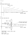
Fig.3 ] A time chart showing a case in which the target deceleration is set by the target deceleration setting means during travel of the saddled vehicle; - [
Fig.4 ] A flowchart showing control contents for detecting the gradient by the gradient detection means of the saddled vehicle; - [
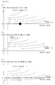
Fig.5 ] Graphs showing a map for detecting the gradient by the gradient detection means of the saddled vehicle; - [
Fig.6 ] A flowchart showing control contents for judging the driver's demand deceleration of vehicle on the basis of the operation conditions of the first brake means, the second brake means and the deceleration increase switch; - [
Fig.7 ] A flowchart showing other control contents for judging the driver's demand deceleration of vehicle on the basis of the operation conditions of the first brake means, the second brake means and the deceleration increase switch; - [
Fig.8 ] A flowchart showing control contents for obtaining the target deceleration set based on the driver's demand deceleration of vehicle judged by detected results of the gradient and the driver's demand judgment means; - [
Fig. 9 ] A graph showing a ratio characteristic map for automatic gear ratio control of the saddled vehicle; - [
Fig.10 ] A graph showing suitability of the deceleration relative to the target deceleration of the saddled vehicle; - [
Fig.11 ] Graphs showing maps for finding the target deceleration of the saddled vehicle; - [
Fig.12 ] Graphs showing maps for finding an initial ratio of the target deceleration of the saddled vehicle; - [
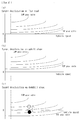
Fig.13 ] Graphs showing concrete cases (cases when traveling from a flat road to a downgrade road) for finding the target deceleration of the saddled vehicle; - [
Fig.14 ] Graphs showing concrete cases (cases when traveling from a flat road to a downgrade road) for finding the initial ratio of the target deceleration of the saddled vehicle; - [
Fig.15 ] Graphs showing concrete cases (cases when the first and second brakes are operated during travel at the downgrade) for finding the target deceleration of the saddled vehicle; - [
Fig.16 ] Graphs showing concrete cases (cases when the first and second brakes are operated during travel at the downgrade) for finding the initial ratio of the target deceleration of the saddled vehicle; - [
Fig.17 ] A block diagram showing a concept of the saddled vehicle according to a second embodiment of the present invention; and - [
Fig.18 ] A schematic view showing a general structure of the saddled vehicle ofFig. 17 . - Preferable embodiments of the present invention will be hereinafter described with reference to the accompanying drawings.
- A saddled vehicle of the first embodiment of the present invention is shown as a two-wheeled vehicle driven by a driver sitting on a saddle seat and steering a bar handle and comprises as shown
Figs. 1 and2 an engine E, a bar handle H, two operation means for braking the vehicle comprising a first brake means 2 and a second brake means 3, atransmission 1 comprising a continuously variable transmission (CVT), a clutch K, anengine ECU 11 as an engine control means, atransmission ECU 4, and a gradient detection means 9. A reference character "ST" denotes a starter for starting the engine E. - The bar handle H is a steering handle one tip end of which is a grasping grip Gb adapted to be gripped by a driver's left hand and the other tip end of which is a throttle grip Ga gripped by a driver's right hand and rotated for accelerator operation. A transmission range operating means 10 for changing the
transmission 1 to a desired mode is also mounted on the bar handle H at the base end position of the grasping grip Gb. Modes ("N" range and "D" range) of thetransmission 1 can be selectively changed with a driver selectively operating the transmission range operating means 10 by his left hand grasping the grip Gb. - The transmission range operating means 10 of the present embodiment is provided with a deceleration increase switch (also referred to as "Fsw switch") 8. The
deceleration increase switch 8 operates to increase a target deceleration set by a target deceleration setting means 7 described later subject to switching operation when the accelerator operation (rotational operation of the throttle grip Ga) is not performed during travel of the vehicle. - The throttle grip Ga can be grasped and operated by a driver with being rotated to open and close a throttle (fuel injection valve) of the engine E and to supply the engine E with fuel to drive the engine E at a desired speed. In addition, a switch case is mounted on the bar handle H at a base end position of the throttle grip Ga for operating various electric parts of the vehicle.
- The first brake means 2 is mounted on the tip end of the bar handle H (extended from base end position of the throttle grip Ga). The first brake means 2 comprises a lever swingably operated by a driver grasping the throttle grip Ga and the two-wheeled vehicle can be braked by a front wheel brake (not shown) when the swing motion of the lever is detected by a brake operation detection sensor S1.
- In addition, the second brake means 3 is mounted on the tip end of the bar handle H (extended from base end position of the grasping grip Gb). Similarly to the first brake means 2, the second brake means 3 comprises a lever swingably operated by a driver grasping the grasping grip Gb and the two-wheeled vehicle can be braked by a rear wheel brake (not shown) when the braking operation of the second brake means 3 is detected by a brake operation detection sensor S2.
- The vehicle of the present embodiment further comprises a detection sensor S3 for detecting whether the throttle grip Ga is grasped or not, an engine rotation sensor S4 and a vehicle speed sensor S7 for detecting a vehicle speed. These detection sensors S3, S7 are electrically connected to the
transmission ECU 4 and can transmit detected signals to thetransmission ECU 4 and the engine rotation sensor S4 is electrically connected to theengine ECU 11 and can transmit detected signals to theengine ECU 11. - The clutch K and the
transmission 1 are arranged on the power transmitting path from the engine E to the driving wheel D. Thetransmission 1 of the present embodiment comprises CVT which can automatically change a gear ratio according to a mode set by the transmission range operating means 10. Thetransmission 1 is controlled by a gear ratio control means 5 and occupies a condition to transmit the driving power of the engine E to the driving wheel D when being set at D range and a condition not to transmit the driving power of the engine E to the driving wheel D by cutting off power transmission with having the clutch "OFF" at the "N" range (neutral range). - The clutch K is a multiple disc clutch in this embodiment arranged on the power transmitting path between the
transmission 1 and the driving wheel D and adapted to transmit and cut off the driving power of the engine E to the driving wheel D at selected timings. The clutch K can be switched between an "ON" state in which the driving power of the engine E can be transmitted to the driving wheel D and an "OFF" state in which the driving power of the engine E cannot be transmitted to the driving wheel D. - The clutch K of the present embodiment is provided with a clutch position angle sensor S5 and a clutch rotation sensor S6 and detected signals from these sensors S5, S6 can be transmitted to the
transmission ECU 4. The press-contacted condition of clutch discs can be grasped from the detected signals and thus can detect the torque capacity (TC) of the clutch K. - The engine ECU (engine control means) 11 comprises a microcomputer etc. for controlling the engine E supplied with electric power from a battery B of vehicle and electrically connected to the
transmission ECU 4 for transmitting and receiving electric signals therebetween. Theengine ECU 11 of the present embodiment can perform the idle-stop with automatically stop the engine when predetermined conditions are satisfied. The "idle-stop" means a control in which the idling rotation of engine E is stopped when predetermined conditions are satisfied to suppress the fuel consumption. - Similarly to the
engine ECU 11, thetransmission ECU 4 comprises a microcomputer etc. and is electrically connected to theengine ECU 11 for transmitting and receiving electric signals therebetween as well as electrically connected to actuators of thetransmission 1 and the clutch K. As shown inFig. 1 , thetransmission ECU 4 is formed of a gear ratio control means 5 for controlling thetransmission 1, a driver's demand judgment means 6 and a target deceleration setting means 7. In this case, the clutch control means for controlling the clutch K may be combined with thetransmission ECU 4. - In addition, the
gradient detection sensor 9 for detecting the gradient of the vehicle during travel is connected to thetransmission ECU 4. Thegradient detecting means 9 may be formed of means for detecting the gradient by a control (operation etc.) described later or an inclination sensor for detecting the inclination angle of vehicle and detecting the gradient of vehicle during travel from the detected inclination angle. When detecting the gradient by operation etc., thegradient detecting means 9 may be arranged within thetransmission ECU 4 or theengine ECU 11. - The driver's demand judgment means 6 of the present embodiment can judge the deceleration of the vehicle demanded by a driver in accordance with operation conditions of the first brake means 2 and the second brake means 3 and is structured so that it can control the vehicle on the basis of deceleration judged by the driver's demand judgment means 6 (more particularly, so that the target deceleration is set by the target deceleration setting means 7 on the basis of the deceleration judged by results of gradient detection and driver's demand judgment means 6 and the vehicle can have the target deceleration set by the target deceleration setting means 7).
- The target deceleration setting means 7 can set the target deceleration on the basis of the deceleration judged by the driver's demand judgment means 6 and is structured in the present embodiment so that the vehicle is controlled to obtain target deceleration set by the target deceleration setting means 7 by controlling the gear ratio of the
transmission 1 as shown inFig. 3 . In this case, the means and method to obtain the target deceleration set by the target deceleration setting means 7 are not limited to those of controlling the gear ratio of thetransmission 1 but may be those for example of adjusting intake resistance by changing the throttle opening during fuel cut of the engine, of adjusting power regeneration amount (regeneration amount during braking) of a motor of a hybrid vehicle or those of combination thereof. - The target deceleration setting means 7 is structured so that it sets the target deceleration larger when both the first brake means 2 and the second brake means 3 are operated than when either one of the first brake means 2 and the second brake means 3 is operated. For example, as shown in
Fig. 3 the driver's demand judge (demand level) when both the first brake means 2 and the second brake means 3 are operated is set higher than that when the second brake means 3 is operated alone. This enables to more accurately judge the driver's demand and thus to set the deceleration further near the driver's demand. - In addition, the target deceleration setting means 7 of the present embodiment is structured as shown in
Fig. 3 so that it does not perform setting or update of the target deceleration when the operation time of the first brake means 2 or the second brake means 3 (period of time of continuous operation) is shorter than a predetermined time (T1, T2) and on the other hand it sets the target deceleration on the basis of the deceleration judged by the driver's demand judgment means 6 or increases the target deceleration when the operation time of the first brake means 2 or the second brake means 3 (period of time of continuous operation) is longer than a predetermined time (T1, T2). - Accordingly, it is possible to prevent the setting or update of the target deceleration relating to the short time operation (operation shorter than the predetermined time (T1, T2)) when performing a short time braking operation as an opportunity of controlling the attitude of the vehicle for example when trying to turn the vehicle to the left or right. This enables to more accurately judge the driver's demand and thus to prevent the deceleration from being adjusted to that different from the driver's demand.
- Furthermore, the first brake means 2 is for braking a front wheel and the second brake means 3 is for braking a rear wheel, and the predetermined time (period of time to be compared with the continuous operation time of the first brake means 2 or the second brake means 3) is set so that the time for operating the second brake means 3 is longer than that for operating the first brake means 2.
- Since the short time braking operation performed as an opportunity of controlling the attitude of the vehicle for example when trying to turn the vehicle to the left or right is usually done for the second brake means 3 (for braking the rear wheel), it is possible to more accurately judge the driver's demand and thus to prevent the deceleration from being adjusted to that different from the driver's demand.
- As shown in
Fig. 3 , the saddled vehicle is structured so that the target deceleration set by the target deceleration setting means 7 is maintained even if the operation of the first brake means 2 or the second brake means 3 is stopped. This makes it possible to continue the engine brake so as to be the set target deceleration even if the operation of the first brake means 2 or the second brake means 3 is stopped for example during travel on a long downgrade and thus possible to reduce the frequency of brake operation as well as to more firmly obtain the deceleration of driver's demand. - In addition, according to the present embodiment, the saddled vehicle is structured so that the target deceleration set by the target deceleration setting means 7 is invalidated subject to the accelerator operation and a control based on the target deceleration is cancelled. This makes it possible to terminate the control based on the target deceleration by accelerator operation and to dispense with separate dedicate operation means and separate special operation for terminating the control.
- Also according to the present embodiment, since the saddled vehicle comprises a
deceleration increase switch 8 for increasing the target deceleration set by the target deceleration setting means 7 subject to a switch operation when the accelerator operation is not performed during travel of the vehicle, it is possible to increase the deceleration by operating thedeceleration increase switch 8 and to more suitably obtain the deceleration of driver's demand for example when the deceleration automatically set by the target deceleration setting means 7 is insufficient. - Further according to the present embodiment, since the saddled vehicle comprises the gradient detection means 9 for detecting a road gradient during travel of a vehicle and the target deceleration setting means 7 sets a reduced target deceleration as compared with a flat gradient when a gradient detected by the
gradient detecting means 9 is a downgrade, it is possible to prevent the vehicle from being adjusted to a different deceleration from the driver's demand during travel on a downgrade road. That is, the target deceleration is set small at a downgrade road and thus this makes it possible to make the deceleration correspondence to the driver's demand when a large deceleration is not required in such a case of travelling on a relatively long and linear downgrade road. - Further according to the present embodiment, since the target deceleration set by the target deceleration setting means 7 is set on the basis of a state in which braking by the first brake means 2 and second brake means 3 is not performed, it is possible to set a suitable target deceleration irrespective of degree of braking (magnitude of braking force) of the first brake means 2 or the second brake means 3. That is, since the target deceleration is achieved by controlling the gear ratio when both the first brake means 2 and second brake means 3 are brake "ON" so that the target deceleration can be achieved when both the brake means 2, 3 are brake "OFF", it is possible to automatically and accurately control the gear ratio even if the deceleration is varied by the braking operation.
- In addition, as other embodiment, the target deceleration setting means 7 can be formed so that the setting or update of the target deceleration is not performed when the increasing deceleration by operation of the first brake means 2 or the second brake means 3 is smaller than a predetermined value (that is, the effect of braking is smaller than a predetermined value) and on the other hand, the setting or upgrade of the target deceleration is performed on the basis of the deceleration judged by the driver's demand judgment means 6 when the increasing deceleration by operation of the first brake means 2 or the second brake means 3 is larger than a predetermined value (that is, the effect of braking is larger than a predetermined value). This makes it possible to more accurately judge the driver's demand and thus to prevent the deceleration from being adjusted to that different from the driver's demand.
- In the other embodiment described above, it is preferable that the first brake means 2 is for braking a front wheel and the second brake means 3 is for braking a rear wheel and that said predetermined value (predetermined value to be compared with the increasing deceleration by operation of the first brake means 2 or the second brake means 3) is set so that the value for operating the second brake means 3 is smaller than that for operating the first brake means 2.
- The weak braking operation performed as an opportunity of controlling the attitude of the vehicle for example when trying to turn the vehicle to the left or right is done using either one of the first brake means 2 (for the front wheel) and the second brake means 3 (for the rear wheel) without necessity of the setting or update of the target deceleration. Since the braking effect of the first brake means 2 is the more effective than that of the second brake means 3, it is possible to accurately judge the driver's demand and surely prevent the deceleration from being adjusted to a different deceleration from that of the driver's demand by setting the predetermined value of the second brake means 3 smaller than that of the first brake means 2.
- Then, the control for detecting the road gradient now on travel according to the gradient detection means 9 of the present embodiment will be described with respect to a flowchart of
Fig. 4 . - First of all, judgments whether the transmission range is set at "D" range by the transmission range operating means 10 (S1), whether the accelerator operation is done (S2) and whether the vehicle speed is higher than the predetermined speed (S3) are performed. When the transmission range is not set at "D" range (i.e. it is set at "N" range), when the accelerator operation is done and when the vehicle speed is not higher than the predetermined speed, these all go to step S13 and it is judged that the road is flat.
- On the other hand, when the "D" range has been set, when the accelerator operation has not been done and when the vehicle speed is higher than the predetermined speed, it goes to step S4 and it is judged whether the first brake means 2 has been operated and whether the second brake means 3 has been operated at step S5. When judged both the first and second brake means 2, 3 has not been operated, it goes to step S6 and the reference deceleration (current gear ratio) is calculated by a map, for example, shown in
Fig. 5(a) . - Then, a current deceleration (a value subtracted a currently measured vehicle speed from a formerly measured vehicle speed) is calculated at step S7 and a comparative deceleration (a value subtracted the current deceleration obtained at S7 from the reference deceleration obtained at S6) is continuously calculated at S8. Then, it is judged at S9 whether the comparative deceleration is smaller than an uphill slope predetermined value (e.g. a predetermined value obtained from a map shown in
Fig. 5(b) ). When judged smaller than the uphill slope predetermined value, it goes to S11 and judges that it is upgrade (uphill slope). When judged the comparative deceleration is not smaller than the uphill predetermined value at S9, it is judged at S10 whether the comparative deceleration is larger than the downhill slope predetermined value (e.g. a predetermined value obtained from a map shown inFig. 5(b) ). When judged larger than the downhill slope predetermined value, it goes to S12 and judges the road is downgrade (downhill slope) and when judges not larger than the downhill slope predetermined value, it goes to S13 and judges the road is flat. - Then, the control for the driver's demand judgment by the driver's demand judgment means 6 of the present embodiment will be described with respect to a flowchart of
Fig. 6 . - First of all, judgments whether the transmission range is set at "D" range by the transmission range operating means 10 (S1), whether the accelerator operation is done (S2) and whether the vehicle speed is higher than the predetermined speed (S3) are performed. When the transmission range is not set at "D" range (i.e. it is set at "N" range), when the accelerator operation is done and when the vehicle speed is not higher than the predetermined speed, these all cases go to step S11, S12 and S13 and the driver's demand is judged respectively as BRAKE 1 (a parameter relating to presence or absence of operation of the first brake means 2)=0, BRAKE 2 (a parameter relating to presence or absence of operation of the second brake means 3)=0 and Fsw (a parameter relating to presence or absence of operation of the deceleration increase switch 8)=0 (in this case, there is no driver's demand for deceleration).
- On the other hand, when the "D" range has been set, when the accelerator operation has not been done and when the vehicle speed is higher than the predetermined speed, it goes to step S4 and it is judged whether the first brake means 2 has been operated longer than the predetermined period of time T1 (see
Fig. 3 ). When judged the first brake means 2 has been operated for a period of time longer than the predetermined period of time T1,BRAKE 1=1 is set (S5). When it is judged the first brake means 2 has not been operated longer than the predetermined period of time T1 at step S4 or whenBRAKE 1=1 is set at step S5, it goes to step S6 and it is judged whether the second brake means 3 has been operated longer than the predetermined period of time T2 (seeFig. 3 ). When it is judged the second brake means 3 has been operated longer than the predetermined period of time T2,BRAKE 2=1 is set at step S7. - In addition, when it is judged the second brake means 3 has not been operated longer than the predetermined period of time T2 at step S6 or when
BRAKE 2=1 is set at step S7, it goes to step S8 and it is judged whether thedeceleration increase switch 8 has been operated twice (Fsw=2). When judged it has been operated twice it goes to step S14. On the other hand, when judged it has not been operated twice, it goes to step S9 and it is judged whether thedeceleration increase switch 8 has been operated (i.e. operation from OFF to ON). When thedeceleration increase switch 8 is operated from OFF to ON, the driver's demand judgment (BRAKE 1+BRAKE 2+Fsw) is performed at S14 after Fsw=Fsw+1 is set at step S10. - Then, the control for the driver's demand judgment by the driver's demand judgment means 6 of the other embodiment will be described with respect to a flowchart of
Fig. 7 . - First of all, judgments whether the transmission range has been set at "D" range by the transmission range operating means 10 (S1), whether the accelerator operation has been done (S2) and whether the vehicle speed has been higher than the predetermined speed (S3) are performed. When the transmission range has not been set at "D" range (i.e. it is set at "N" range), when the accelerator operation has been done and when the vehicle speed has not been higher than the predetermined speed, these all cases go to steps S11, S12 and S13 and the driver's demand is judged respectively as BRAKE 1 (a parameter relating to presence or absence of operation of the first brake means 2)=0, BRAKE 2 (a parameter relating to presence or absence of operation of the second brake means 3)=0 and Fsw (a parameter relating to presence or absence of operation of the deceleration increase switch 8)=0 (in this case, there is no driver's demand for deceleration).
- On the other hand, when the "D" range has been set, when the accelerator operation has not been done and when the vehicle speed has been higher than the predetermined speed, it goes to step S4 and it is judged whether the second brake means 3 has been operated. When judged the second brake means 3 has not been operated, it goes to step S14 and it is judged whether the first brake means 2 has been operated. When judged the first brake means 2 has been operated at step S14, it is judged whether the deceleration increased by the operation of the first brake means 2 is larger than a predetermined value A1 (S15). When the increase deceleration is larger than the predetermined value A1,
BRAKE 1=1 is set at S16 and when judged the first brake means 2 has not been operated at step S14, it goes to step S17 and memorizes a current deceleration as a deceleration under state in which both the brakes are "OFF" for judging the increase deceleration during braking operation. - When judged the second brake means 3 has been operated at step S4, it goes to step S5 and is judged whether the first brake means 2 has been operated. When the first brake means 2 has not been operated, it goes to step S6 and is judged whether the deceleration increased by operation of the second brake means 3 is larger than a predetermined value A2. When larger than the predetermined value A2, it goes to step S7 and
BRAKE 2=1 is set at step S7. - Furthermore, when judged the first brake means 2 has been operated at S5, it goes to step S18 and is judged whether the deceleration increased by operations of the first brake means 2 and the second brake means 3 is larger than a predetermined value A3. When larger than the predetermined value A3, it goes to step S19 and
BRAKE 1=1 is set and then BRAKE 2=1 is set at step S20. After steps S16, S17, S7 and S20, it is judged whether thedeceleration increase switch 8 has been operated twice (Fsw=2). When not operated twice, it goes to step S9 and judges whether thedeceleration increase switch 8 has been operated ((i.e. operation from OFF to ON). When thedeceleration increase switch 8 has been operated from OFF to ON, a driver's demand judgment (BRAKE 1+BRAKE 2+Fsw) is performed at step S21 after setting of Fsw=Fsw+1 at step S10. In this case, the predetermined value are set as an order A1 > A2 > A3 in accordance with difference in the braking effect so that presence or absence of the demand of deceleration can be judged from the increased deceleration by braking as a demand of a driver (see steps S15, S6 and S18). Any case when judged the increase deceleration is not larger than A1 at step S15, when judged the deceleration increased by the operation of the second brake means 3 is not larger than A2 at step S6 and when the increase deceleration is not larger than A3 at step S18 go to step S8 and the controls described above are performed. - Then, a control for setting the target deceleration (the target deceleration and the target gear ratio in the present embodiment) by the target deceleration setting means 7 of the present embodiment will be described with respect to a flowchart of
Fig. 8 . - First of all, judgments whether the transmission range has been set at "D" range by the transmission range operating means 10 (S1), whether the accelerator operation has been done (S2) and whether the vehicle speed has been higher than the predetermined speed (S3) are performed. When the transmission range has not been set at "D" range (i.e. it is set at "N" range), when the accelerator operation has been done and when the vehicle speed has not been higher than the predetermined speed, these all go to step S12 and the target gear ratio is set by an automatic gear ratio control map shown in
Fig. 9 . - On the other hand, when the "D" range has been set, when the accelerator operation has not been done and when the vehicle speed has been higher than the predetermined speed, it goes to step S4 and the target deceleration can be found on the basis of a target deceleration map. As shown in
Fig. 11 , the target deceleration map is different between cases of flat road (Fig. 11(a) ), of uphill slope (Fig. 11(b) ) and of downhill road (Fig. 11(c) ) and intended to be able to find the target deceleration on the basis of the road gradient, the driver's demand and the vehicle speed. - Then, it goes to step S5 to judge whether a predetermined period of time has been passed from the beginning of the deceleration control after the target deceleration having been found at step S4. When the predetermined period of time has not been passed, it goes to step S10 to find the target gear ratio (in this case an initial gear ratio for the target deceleration) from a map (initial gear ratio map for the target deceleration). As shown in
Fig. 12 , the initial gear ratio map for the target deceleration is different between cases of flat road (Fig. 12(a) ), of uphill slope (Fig. 12(b) ) and of downhill road (Fig. 12 (c) ) and intended to be able to find the initial gear ratio for the target deceleration on the basis of the road gradient, the target deceleration and the vehicle speed. - When the predetermined period of time has been passed from the start of the deceleration control at step S5, it goes to step S6 to judge operation of the first brake means 2 or second brake means 3 has been performed. When none of the brake means 2 or 3 is operated, it goes to step S7 to judge whether the deceleration caused by engine brake is larger than a value which is obtained by adding a preset minute value (Δdeceleration) to the target deceleration. When judged at step S7 that the deceleration caused by engine brake is larger than the value which is obtained by adding Δdeceleration to the target deceleration, it is judged this is excessive deceleration as shown in
Fig. 10 . Accordingly, it goes to step S11 and the target gear ratio is determined as a value which is obtained by subtracting the preset minute value (Δgear ratio) from the current target gear ratio. When no brake operation is performed at step S6, the target gear ratio is not changed. - When judged at step S7 that the deceleration caused by engine brake is not larger than the value which is obtained by adding Δdeceleration to the target deceleration, it goes to step S8 and judges whether the deceleration is smaller than the target deceleration. When judged the deceleration is not smaller than the target deceleration, it is judged this is moderate deceleration as shown in
Fig. 10 . Accordingly, it goes to step S13 and performs a feedback control (FB control) based on the set target gear ratio. On the other hand, when judged the deceleration is smaller than the target deceleration at step S8, it is judged this is deficient deceleration as shown inFig. 10 . Accordingly, it goes to step S9 and the target gear ratio is determined as a value which is obtained by adding the preset minute value (Δgear ratio) to the current target gear ratio. - Then, concrete examples of setting the target deceleration and the target gear ratio by using the target deceleration setting means 7 of the present embodiment will be described on the basis of a target deceleration map of
Fig. 13 and an initial gear ratio map for the target deceleration ofFig. 14 . For example, when performing the accelerator OFF (without brake operation) during travel at normal speed (about 50 km/h) on a flat road, the target deceleration (substantially deceleration = 0) shown inFig. 13 (a) by a black round mark (•) is set. In order to achieve the target deceleration, the target gear ratio shown by the black round mark inFig. 14(a) is selected as the initial gear ratio and a later feedback control (FB control) is performed. Then when the road condition is changed from flat to downhill slope, the target deceleration is changed to a slight acceleration shown by a white round mark (∘) inFig. 13(c) . In order to achieve the target deceleration, the target gear ratio shown inFig. 14(c) is changed from the black round mark to the white round mark and the later feedback control is performed. - Then, concrete examples of setting the target deceleration and the target gear ratio by using the target deceleration setting means 7 of the present embodiment will be described on the basis of a target deceleration map of
Fig. 15 and an initial gear ratio map for the target deceleration ofFig. 16 . For example, when the first brake means 2 and the second brake means 3 are operated during travel at normal speed (about 50 km/h) on a downhill slope with performing accelerator OFF and without brake operation, it is judged the driver's demand is changed from 0 to 2 and the target deceleration shown by a black round mark inFig. 15(c) is set as a white round mark (slight deceleration). In order to achieve the target deceleration, the target gear ratio shown inFig. 16(c) is changed from the black round mark to the white round mark and the later feedback control is performed. - Then a second embodiment of the present invention will be described. A saddled vehicle of the second embodiment of the present invention is a two-wheeled vehicle driven by a driver sitting on a saddle seat and steering a bar handle and comprises as shown
Figs. 17 and18 an engine E, a bar handle H, two operation means for performing a braking operation including a first brake means 2 and a second brake means 12, a stepwise transmission 1', a clutch K, anengine ECU 11 as an engine control means, atransmission ECU 4, and a gradient detection means 9. Same reference numerals are used also in this second embodiment as those used in the first embodiment and detailed description of them will be omitted. - In the two-wheeled vehicle of the present embodiment, the second brake means 12 operated by a driver's foot is mounted. The second brake means 12 comprises a foot brake operated by a foot of driver sitting on the saddled seat and the two-wheeled vehicle can be braked by a rear wheel brake (not shown) when the foot motion of a driver is detected by a brake operation detection sensor S2.
- Similarly to the first embodiment, the transmission 1' and the clutch K are arranged on the power transmitting path from the engine E to the driving wheel D. The transmission 1' is stepwise transmission provided with a dog clutch which can be automatically shifted to a predetermined gear step in accordance with modes set by the transmission range operating means 10. The transmission 1' can be controlled by the gear ratio control means 5 and adapted to transmit the driving power of the engine E to the driving wheel D when it is set to the "D" range (1st gear ⇔ 2nd gear ⇔3rd gear ⇔ 4th gear automatic gear ratio control in this embodiment) and not to transmit the driving power of the engine E to the driving wheel D when it is set to the "N" range.
- As shown in
Fig. 18 , thetransmission ECU 4 is further electrically connected to the vehicle-speed sensor S7 and a shift-drum angle sensor S8 for detecting states (states of transmission and interruption of power) of the dog clutch of the transmission 1' to grasp states of the vehicle speed and the dog clutch. A reference numeral S4 denotes an engine rotation sensor electrically connected to theengine ECU 11. - Similarly to the first embodiment, a driver's demand judgment means 6 of this embodiment can judge the deceleration of the vehicle demanded by a driver in accordance with operation conditions of the first brake means 2 and the second brake means 12 and is structured so that it can control the vehicle on the basis of deceleration judged by the driver's demand judgment means 6 (more particularly so that the target deceleration is set by the target deceleration setting means 7 on the basis of the deceleration judged by results of gradient detection and driver's demand judgment means 6 and the vehicle can have the target deceleration set by the target deceleration setting means 7).
- The target deceleration setting means 7 can set the target deceleration on the basis of the deceleration judged by the driver's demand judgment means 6 and is structured, similarly to the first embodiment, so that the vehicle is controlled to obtain target deceleration set by the target deceleration setting means 7 by controlling the gear ratio of the transmission 1'. In this case, the means and method to obtain the target deceleration set by the target deceleration setting means 7 are not limited to those of controlling the gear ratio of the transmission 1' and may be those for example of adjusting intake resistance by changing the throttle opening during fuel cut of the engine, of adjusting power regeneration amount (regeneration amount during braking) of a motor of a hybrid vehicle or those of combination thereof.
- According to the first and second embodiments, since the saddled vehicle comprises a driver's demand judgment means 6 for judging the deceleration of the vehicle demanded by the driver in accordance with operation conditions of the first brake means 2 and the second brake means (3, 12) and is able to control the vehicle on the basis of the deceleration judged by the driver's demand judgment means 6, it is possible to obtain the driver's deceleration demand more accurately by properly using operations of the first brake means 2 and the second brake means (3, 12) peculiar to the saddled vehicle as compared with two-wheeled vehicles provided with single brake means. In addition, since the driver's demand judgment means also judges the road gradient in operations of the first and second brake means, it is possible to further accurately obtain the driver's deceleration demand. Accordingly, it is possible to instantaneously apply the engine brake in accordance with driver's demand even if travelling under the automatic gear ratio control and also possible to dispense with a separate dedicate operation means and a separate special operation for applying the engine brake.
- In addition, according to the first and second embodiments, since the saddled vehicle further comprises a target deceleration setting means 7 for setting a target deceleration on the basis of the deceleration judged by the driver's demand judgment means 6 to control the vehicle as having the target deceleration set by the target deceleration setting means 7, it is possible to have the deceleration along the driver's demand. Furthermore, since the vehicle is controlled to obtain target deceleration set by the target deceleration setting means 7 by controlling the gear ratio of the transmission (1, 1'), it is possible to more accurately and rapidly obtain the target deceleration with applying the engine brake.
- Although it is described the saddled vehicle of the present embodiments, the present invention is not limited to the described and illustrated embodiments. Accordingly, it may be possible to apply engine brake by changing the gear ratio with judging the deceleration of the vehicle of driver's demand by the driver's demand judgment means 6 in accordance with operational conditions of the first and second brake means without using the target deceleration setting means 7. In addition, the first brake means 2 is not limited to the operation means arranged at a tip end of the bar handle H to which the throttle grip Ga is mounted. Furthermore, the saddled vehicle of the present invention is not limited to the described and illustrated two-wheeled vehicle and thus may be applied to any other types of vehicles such as those driven by a driver sitting on a saddled seat and steered by a bar handle.
- The present invention can be applied to other saddled vehicles having different appearances and other functions than those described in this application if they are saddled vehicles comprising a driver's demand judgment means for judging the deceleration of the vehicle demanded by the driver in accordance with operation conditions of the first brake means and the second brake means, and a deceleration adjustment means is able to control the vehicle on the basis of the deceleration judged by the driver's demand judgment means.
-
- 1
- transmission (CVT)
- 1'
- transmission (stepwise variable transmission)
- 2
- first brake means
- 3
- second brake means
- 4
- transmission ECU
- 5
- gear ratio control means
- 6
- driver's demand judgment means
- 7
- target deceleration setting means
- 8
- deceleration increase switch
- 9
- gradient detection means
- 10
- transmission range operating means
- 11
- engine ECU (engine control means)
- 12
- second brake means
- H
- bar handle
- E
- engine
Claims (13)
- A saddled vehicle driven by a driver sitting on a saddle seat with steering a bar handle comprising:a bar handle (H) on both tip ends of which are provided with a grasping grip (Gb) to be grasped by a driver and a throttle grip (Ga) for an accelerator operation;a first brake means (2) and a second brake means (3) including two operation means for performing a braking operation, at least one of which being mounted on the tip end of the bar handle (H);a gradient detection means (9) for detecting a road gradient during travel of a vehicle; anda deceleration adjustment means for automatically adjusting the deceleration of the vehicle in accordance with the road gradient detected by the gradient detection means (9) characterized in:that the saddled vehicle further comprises a driver's demand judgment means (6) for judging the deceleration of the vehicle demanded by the driver in accordance with operation conditions of the first brake means (2) and the second brake means (3) and the road gradient detected by the gradient detection means (9), andthat the deceleration adjustment means is able to control the vehicle on the basis of the deceleration judged by the driver's demand judgment means (6).
- A saddled vehicle of claim 1 wherein the saddled vehicle further comprises a target deceleration setting means (7) for setting a target deceleration on the basis of the deceleration judged by the driver's demand judgment means (6) to control the vehicle as having the target deceleration set by the target deceleration setting means (7).
- A saddled vehicle of claim 2 wherein the target deceleration setting means (7) sets the target deceleration larger when both the first brake means (2) and the second brake means (3) are operated than when either one of the first brake means (2) and the second brake means (3) is operated.
- A saddled vehicle of claim 2 wherein the target deceleration setting means (7) does not perform setting or update of the target deceleration when an operation time of the first brake means (2) or the second brake means (3) is shorter than a predetermined time and performs setting of the target deceleration or increase of the set target deceleration on the basis of the deceleration judged by the driver's demand judgment means (6) when an operation time of the first brake means (2) or the second brake means (3) is longer than the predetermined time.
- A saddled vehicle of claim 4 wherein the first brake means (2) is for braking a front wheel and the second brake means (3) is for braking a rear wheel, and wherein said predetermined time is set so that the time for operating the second brake means (3) is longer than that for operating the first brake means (2).
- A saddled vehicle of claim 2 wherein the target deceleration setting means (7) does not perform setting or update of the target deceleration when the deceleration increased by the operation of the first brake means (2) or the second brake means (3) is smaller than a predetermined value and performs setting of the target deceleration or increase of the set target deceleration on the basis of the deceleration judged by the driver's demand judgment means (6) when the deceleration increased by the operation of the first brake means (2) or the second brake means (3) is larger than the predetermined value.
- A saddled vehicle of claim 6 wherein the first brake means (2) is for braking a front wheel and the second brake means (3) is for braking a rear wheel, and wherein said predetermined value is set so that the value for operating the second brake means (3) is smaller than that for operating the first brake means (2).
- A saddled vehicle of any one of claims 2∼7 wherein the saddled vehicle further comprises a deceleration increase switch (8) for increasing the target deceleration set by the target deceleration setting means (7) subject to a switch operation when the accelerator operation is not performed during travel of the vehicle.
- A saddled vehicle of any one of claims 2∼8 wherein the target deceleration set by the target deceleration setting means (7) is invalidated subject to the accelerator operation and a control based on the target deceleration is cancelled.
- A saddled vehicle of any one of claims 2∼9 wherein the target deceleration set by the target deceleration setting means (7) is maintained even if the operation of the first brake means (2) or the second brake means (3) is stopped.
- A saddled vehicle of any one of claims 2∼10 wherein the target deceleration setting means (7) sets a reduced target deceleration when a gradient detected by the gradient detecting means (9) is a downgrade.
- A saddled vehicle of any one of claims 2∼11 wherein the vehicle is controlled so as to have the target deceleration set by the target deceleration setting means (7) by controlling the gear ratio of a transmission (1, 1') of the vehicle.
- A saddled vehicle of any one of claims 2∼12 wherein the target deceleration to be set by the target deceleration setting means (7) is set on the basis of a condition in which braking due to both the first brake means (2) and the second brake means (3) has not been performed.
Applications Claiming Priority (1)
| Application Number | Priority Date | Filing Date | Title |
|---|---|---|---|
| PCT/JP2014/051397 WO2015111168A1 (en) | 2014-01-23 | 2014-01-23 | Saddled vehicle |
Publications (3)
| Publication Number | Publication Date |
|---|---|
| EP3098482A1 true EP3098482A1 (en) | 2016-11-30 |
| EP3098482A4 EP3098482A4 (en) | 2017-12-06 |
| EP3098482B1 EP3098482B1 (en) | 2020-08-05 |
Family
ID=53680999
Family Applications (1)
| Application Number | Title | Priority Date | Filing Date |
|---|---|---|---|
| EP14879639.4A Active EP3098482B1 (en) | 2014-01-23 | 2014-01-23 | Saddled vehicle |
Country Status (5)
| Country | Link |
|---|---|
| US (1) | US9981661B2 (en) |
| EP (1) | EP3098482B1 (en) |
| JP (1) | JP6185606B2 (en) |
| CN (1) | CN106415078B (en) |
| WO (1) | WO2015111168A1 (en) |
Families Citing this family (10)
| Publication number | Priority date | Publication date | Assignee | Title |
|---|---|---|---|---|
| US9216789B2 (en) * | 2012-11-12 | 2015-12-22 | Indian Motorcycle International, LLC | Two-wheeled vehicle |
| US9394859B2 (en) | 2012-11-12 | 2016-07-19 | Indian Motorcycle International, LLC | Two-wheeled vehicle |
| JP2018070080A (en) * | 2016-11-04 | 2018-05-10 | ローベルト ボッシュ ゲゼルシャフト ミット ベシュレンクテル ハフツング | Control device for controlling brake force generated on wheel by vehicle brake system, and control method |
| JP6973917B2 (en) * | 2017-08-22 | 2021-12-01 | ダイハツ工業株式会社 | Control device for continuously variable transmission |
| EP3680137B1 (en) * | 2017-12-28 | 2021-09-01 | Honda Motor Co., Ltd. | Brake device for saddle-type vehicles |
| DE102018221720A1 (en) * | 2018-12-13 | 2020-06-18 | Robert Bosch Gmbh | Method and device for performing autonomous braking in a single-track motor vehicle |
| JP7035995B2 (en) * | 2018-12-25 | 2022-03-15 | トヨタ自動車株式会社 | Driving support device |
| DE102019209864A1 (en) | 2019-07-04 | 2021-01-07 | Robert Bosch Gmbh | Method and device for performing autonomous braking in a single-track motor vehicle |
| JP2021128591A (en) * | 2020-02-14 | 2021-09-02 | ロベルト・ボッシュ・ゲゼルシャフト・ミト・ベシュレンクテル・ハフツングRobert Bosch Gmbh | Control device and control method |
| JP7507258B2 (en) * | 2021-01-22 | 2024-06-27 | 本田技研工業株式会社 | Saddle type vehicle |
Family Cites Families (21)
| Publication number | Priority date | Publication date | Assignee | Title |
|---|---|---|---|---|
| JPH02102969A (en) | 1988-10-11 | 1990-04-16 | Honda Motor Co Ltd | Speed change ratio control device of continuously variable transmission for vehicle |
| JP4361385B2 (en) * | 2004-01-30 | 2009-11-11 | 本田技研工業株式会社 | Motorcycle brake equipment |
| JP2005271822A (en) * | 2004-03-25 | 2005-10-06 | Mitsubishi Fuso Truck & Bus Corp | Vehicular automatic deceleration control device |
| US8226527B2 (en) * | 2004-07-09 | 2012-07-24 | Yamaha Hatsudoki Kabushiki Kaisha | Straddle type vehicle and speed change control unit of continuously variable transmission |
| CN100470412C (en) * | 2004-08-05 | 2009-03-18 | 雅马哈发动机株式会社 | Vehicle control device and vehicle |
| JP4911995B2 (en) * | 2006-03-07 | 2012-04-04 | ヤマハ発動機株式会社 | Motorcycle |
| JP4842672B2 (en) * | 2006-03-07 | 2011-12-21 | ヤマハ発動機株式会社 | Motorcycle |
| JP4602279B2 (en) * | 2006-03-31 | 2010-12-22 | 日信工業株式会社 | Brake control device for motorcycle |
| CN101074728B (en) * | 2006-05-16 | 2013-03-13 | 韩群山 | Clutch gearshift intelligent controlling system and method for motorcycle |
| DE102007025273A1 (en) * | 2006-06-14 | 2008-01-03 | Continental Teves Ag & Co. Ohg | Method for regulating the pressure in an electronically controlled braking system and electronic braking system |
| JP5226285B2 (en) * | 2007-04-27 | 2013-07-03 | ヤマハ発動機株式会社 | Saddle-type vehicle control device, transmission, and saddle-type vehicle |
| JP5261758B2 (en) * | 2007-08-31 | 2013-08-14 | 本田技研工業株式会社 | Automatic transmission control device for vehicle |
| JP4998736B2 (en) * | 2007-12-28 | 2012-08-15 | スズキ株式会社 | Automatic transmission control device for motorcycle |
| JP5247313B2 (en) * | 2008-09-01 | 2013-07-24 | ヤマハ発動機株式会社 | Control system and vehicle |
| JP5107184B2 (en) * | 2008-09-01 | 2012-12-26 | ヤマハ発動機株式会社 | Control system and vehicle |
| DE102010030984A1 (en) * | 2010-07-06 | 2012-01-12 | Continental Teves Ag & Co. Ohg | Method for determining a vehicle reference speed and brake system |
| JP5779325B2 (en) * | 2010-07-21 | 2015-09-16 | 川崎重工業株式会社 | Vehicle deceleration control device |
| JP5478739B2 (en) * | 2010-12-28 | 2014-04-23 | 川崎重工業株式会社 | Regenerative control system for electric vehicles |
| CN103287426B (en) * | 2010-12-29 | 2015-12-02 | 浙江钱江摩托股份有限公司 | A kind of control setup of parallel mild hybrid power motorcycle |
| JP5634295B2 (en) * | 2011-02-22 | 2014-12-03 | 本田技研工業株式会社 | Attitude control device and attitude control method for motorcycle |
| KR20130025149A (en) * | 2011-09-01 | 2013-03-11 | 주식회사 현대케피코 | Transmission for activating engine brake automatically and method thereof |
-
2014
- 2014-01-23 JP JP2015558647A patent/JP6185606B2/en active Active
- 2014-01-23 EP EP14879639.4A patent/EP3098482B1/en active Active
- 2014-01-23 CN CN201480073777.9A patent/CN106415078B/en active Active
- 2014-01-23 WO PCT/JP2014/051397 patent/WO2015111168A1/en active Application Filing
-
2016
- 2016-07-22 US US15/217,500 patent/US9981661B2/en active Active
Also Published As
| Publication number | Publication date |
|---|---|
| US9981661B2 (en) | 2018-05-29 |
| US20170057513A1 (en) | 2017-03-02 |
| JPWO2015111168A1 (en) | 2017-03-23 |
| WO2015111168A1 (en) | 2015-07-30 |
| CN106415078A (en) | 2017-02-15 |
| CN106415078B (en) | 2018-04-17 |
| EP3098482A4 (en) | 2017-12-06 |
| EP3098482B1 (en) | 2020-08-05 |
| JP6185606B2 (en) | 2017-08-23 |
Similar Documents
| Publication | Publication Date | Title |
|---|---|---|
| EP3098482B1 (en) | Saddled vehicle | |
| US10336329B2 (en) | Saddled vehicle | |
| US10730516B2 (en) | Saddled vehicle | |
| EP3072761B1 (en) | Control device of vehicle | |
| EP2527217B1 (en) | Brake control system in vehicle | |
| CN103781655B (en) | Electric vehicle | |
| EP2990277B1 (en) | Braking force control apparatus for saddle ride-type vehicle | |
| JP5711820B2 (en) | Electric vehicle | |
| US9873484B2 (en) | Saddle-type vehicle | |
| WO2010134304A1 (en) | Device and method for cruise control of vehicles | |
| KR19980081709A (en) | Control device and control method of vehicle | |
| GB2494546A (en) | Vehicle speed-change control device | |
| US10099748B2 (en) | Saddle-type vehicle | |
| JP2015034569A (en) | Shift control device for vehicle | |
| US20160221641A1 (en) | Saddle-type vehicle | |
| KR101548914B1 (en) | Electric vehicle | |
| JP6099254B2 (en) | Vehicle transmission |
Legal Events
| Date | Code | Title | Description |
|---|---|---|---|
| PUAI | Public reference made under article 153(3) epc to a published international application that has entered the european phase |
Free format text: ORIGINAL CODE: 0009012 |
|
| 17P | Request for examination filed |
Effective date: 20160809 |
|
| AK | Designated contracting states |
Kind code of ref document: A1 Designated state(s): AL AT BE BG CH CY CZ DE DK EE ES FI FR GB GR HR HU IE IS IT LI LT LU LV MC MK MT NL NO PL PT RO RS SE SI SK SM TR |
|
| AX | Request for extension of the european patent |
Extension state: BA ME |
|
| DAX | Request for extension of the european patent (deleted) | ||
| REG | Reference to a national code |
Ref country code: DE Ref legal event code: R079 Ref document number: 602014068745 Country of ref document: DE Free format text: PREVIOUS MAIN CLASS: F16H0061020000 Ipc: B60T0008170000 |
|
| A4 | Supplementary search report drawn up and despatched |
Effective date: 20171107 |
|
| RIC1 | Information provided on ipc code assigned before grant |
Ipc: B60T 8/32 20060101ALI20171030BHEP Ipc: B60T 8/17 20060101AFI20171030BHEP Ipc: B60T 8/26 20060101ALI20171030BHEP |
|
| GRAP | Despatch of communication of intention to grant a patent |
Free format text: ORIGINAL CODE: EPIDOSNIGR1 |
|
| STAA | Information on the status of an ep patent application or granted ep patent |
Free format text: STATUS: GRANT OF PATENT IS INTENDED |
|
| INTG | Intention to grant announced |
Effective date: 20191218 |
|
| GRAJ | Information related to disapproval of communication of intention to grant by the applicant or resumption of examination proceedings by the epo deleted |
Free format text: ORIGINAL CODE: EPIDOSDIGR1 |
|
| STAA | Information on the status of an ep patent application or granted ep patent |
Free format text: STATUS: REQUEST FOR EXAMINATION WAS MADE |
|
| GRAP | Despatch of communication of intention to grant a patent |
Free format text: ORIGINAL CODE: EPIDOSNIGR1 |
|
| STAA | Information on the status of an ep patent application or granted ep patent |
Free format text: STATUS: GRANT OF PATENT IS INTENDED |
|
| INTC | Intention to grant announced (deleted) | ||
| INTG | Intention to grant announced |
Effective date: 20200221 |
|
| GRAS | Grant fee paid |
Free format text: ORIGINAL CODE: EPIDOSNIGR3 |
|
| GRAA | (expected) grant |
Free format text: ORIGINAL CODE: 0009210 |
|
| STAA | Information on the status of an ep patent application or granted ep patent |
Free format text: STATUS: THE PATENT HAS BEEN GRANTED |
|
| AK | Designated contracting states |
Kind code of ref document: B1 Designated state(s): AL AT BE BG CH CY CZ DE DK EE ES FI FR GB GR HR HU IE IS IT LI LT LU LV MC MK MT NL NO PL PT RO RS SE SI SK SM TR |
|
| REG | Reference to a national code |
Ref country code: GB Ref legal event code: FG4D |
|
| REG | Reference to a national code |
Ref country code: CH Ref legal event code: EP |
|
| REG | Reference to a national code |
Ref country code: AT Ref legal event code: REF Ref document number: 1298306 Country of ref document: AT Kind code of ref document: T Effective date: 20200815 |
|
| REG | Reference to a national code |
Ref country code: DE Ref legal event code: R096 Ref document number: 602014068745 Country of ref document: DE |
|
| REG | Reference to a national code |
Ref country code: IE Ref legal event code: FG4D |
|
| REG | Reference to a national code |
Ref country code: LT Ref legal event code: MG4D |
|
| REG | Reference to a national code |
Ref country code: NL Ref legal event code: MP Effective date: 20200805 |
|
| REG | Reference to a national code |
Ref country code: AT Ref legal event code: MK05 Ref document number: 1298306 Country of ref document: AT Kind code of ref document: T Effective date: 20200805 |
|
| PG25 | Lapsed in a contracting state [announced via postgrant information from national office to epo] |
Ref country code: HR Free format text: LAPSE BECAUSE OF FAILURE TO SUBMIT A TRANSLATION OF THE DESCRIPTION OR TO PAY THE FEE WITHIN THE PRESCRIBED TIME-LIMIT Effective date: 20200805 Ref country code: PT Free format text: LAPSE BECAUSE OF FAILURE TO SUBMIT A TRANSLATION OF THE DESCRIPTION OR TO PAY THE FEE WITHIN THE PRESCRIBED TIME-LIMIT Effective date: 20201207 Ref country code: ES Free format text: LAPSE BECAUSE OF FAILURE TO SUBMIT A TRANSLATION OF THE DESCRIPTION OR TO PAY THE FEE WITHIN THE PRESCRIBED TIME-LIMIT Effective date: 20200805 Ref country code: LT Free format text: LAPSE BECAUSE OF FAILURE TO SUBMIT A TRANSLATION OF THE DESCRIPTION OR TO PAY THE FEE WITHIN THE PRESCRIBED TIME-LIMIT Effective date: 20200805 Ref country code: BG Free format text: LAPSE BECAUSE OF FAILURE TO SUBMIT A TRANSLATION OF THE DESCRIPTION OR TO PAY THE FEE WITHIN THE PRESCRIBED TIME-LIMIT Effective date: 20201105 Ref country code: SE Free format text: LAPSE BECAUSE OF FAILURE TO SUBMIT A TRANSLATION OF THE DESCRIPTION OR TO PAY THE FEE WITHIN THE PRESCRIBED TIME-LIMIT Effective date: 20200805 Ref country code: AT Free format text: LAPSE BECAUSE OF FAILURE TO SUBMIT A TRANSLATION OF THE DESCRIPTION OR TO PAY THE FEE WITHIN THE PRESCRIBED TIME-LIMIT Effective date: 20200805 Ref country code: NO Free format text: LAPSE BECAUSE OF FAILURE TO SUBMIT A TRANSLATION OF THE DESCRIPTION OR TO PAY THE FEE WITHIN THE PRESCRIBED TIME-LIMIT Effective date: 20201105 Ref country code: GR Free format text: LAPSE BECAUSE OF FAILURE TO SUBMIT A TRANSLATION OF THE DESCRIPTION OR TO PAY THE FEE WITHIN THE PRESCRIBED TIME-LIMIT Effective date: 20201106 Ref country code: FI Free format text: LAPSE BECAUSE OF FAILURE TO SUBMIT A TRANSLATION OF THE DESCRIPTION OR TO PAY THE FEE WITHIN THE PRESCRIBED TIME-LIMIT Effective date: 20200805 |
|
| PG25 | Lapsed in a contracting state [announced via postgrant information from national office to epo] |
Ref country code: IS Free format text: LAPSE BECAUSE OF FAILURE TO SUBMIT A TRANSLATION OF THE DESCRIPTION OR TO PAY THE FEE WITHIN THE PRESCRIBED TIME-LIMIT Effective date: 20201205 Ref country code: RS Free format text: LAPSE BECAUSE OF FAILURE TO SUBMIT A TRANSLATION OF THE DESCRIPTION OR TO PAY THE FEE WITHIN THE PRESCRIBED TIME-LIMIT Effective date: 20200805 Ref country code: PL Free format text: LAPSE BECAUSE OF FAILURE TO SUBMIT A TRANSLATION OF THE DESCRIPTION OR TO PAY THE FEE WITHIN THE PRESCRIBED TIME-LIMIT Effective date: 20200805 Ref country code: NL Free format text: LAPSE BECAUSE OF FAILURE TO SUBMIT A TRANSLATION OF THE DESCRIPTION OR TO PAY THE FEE WITHIN THE PRESCRIBED TIME-LIMIT Effective date: 20200805 Ref country code: LV Free format text: LAPSE BECAUSE OF FAILURE TO SUBMIT A TRANSLATION OF THE DESCRIPTION OR TO PAY THE FEE WITHIN THE PRESCRIBED TIME-LIMIT Effective date: 20200805 |
|
| PG25 | Lapsed in a contracting state [announced via postgrant information from national office to epo] |
Ref country code: RO Free format text: LAPSE BECAUSE OF FAILURE TO SUBMIT A TRANSLATION OF THE DESCRIPTION OR TO PAY THE FEE WITHIN THE PRESCRIBED TIME-LIMIT Effective date: 20200805 Ref country code: SM Free format text: LAPSE BECAUSE OF FAILURE TO SUBMIT A TRANSLATION OF THE DESCRIPTION OR TO PAY THE FEE WITHIN THE PRESCRIBED TIME-LIMIT Effective date: 20200805 Ref country code: EE Free format text: LAPSE BECAUSE OF FAILURE TO SUBMIT A TRANSLATION OF THE DESCRIPTION OR TO PAY THE FEE WITHIN THE PRESCRIBED TIME-LIMIT Effective date: 20200805 Ref country code: DK Free format text: LAPSE BECAUSE OF FAILURE TO SUBMIT A TRANSLATION OF THE DESCRIPTION OR TO PAY THE FEE WITHIN THE PRESCRIBED TIME-LIMIT Effective date: 20200805 Ref country code: CZ Free format text: LAPSE BECAUSE OF FAILURE TO SUBMIT A TRANSLATION OF THE DESCRIPTION OR TO PAY THE FEE WITHIN THE PRESCRIBED TIME-LIMIT Effective date: 20200805 |
|
| REG | Reference to a national code |
Ref country code: DE Ref legal event code: R097 Ref document number: 602014068745 Country of ref document: DE |
|
| PG25 | Lapsed in a contracting state [announced via postgrant information from national office to epo] |
Ref country code: AL Free format text: LAPSE BECAUSE OF FAILURE TO SUBMIT A TRANSLATION OF THE DESCRIPTION OR TO PAY THE FEE WITHIN THE PRESCRIBED TIME-LIMIT Effective date: 20200805 |
|
| PLBE | No opposition filed within time limit |
Free format text: ORIGINAL CODE: 0009261 |
|
| STAA | Information on the status of an ep patent application or granted ep patent |
Free format text: STATUS: NO OPPOSITION FILED WITHIN TIME LIMIT |
|
| PG25 | Lapsed in a contracting state [announced via postgrant information from national office to epo] |
Ref country code: SK Free format text: LAPSE BECAUSE OF FAILURE TO SUBMIT A TRANSLATION OF THE DESCRIPTION OR TO PAY THE FEE WITHIN THE PRESCRIBED TIME-LIMIT Effective date: 20200805 |
|
| 26N | No opposition filed |
Effective date: 20210507 |
|
| PG25 | Lapsed in a contracting state [announced via postgrant information from national office to epo] |
Ref country code: IT Free format text: LAPSE BECAUSE OF FAILURE TO SUBMIT A TRANSLATION OF THE DESCRIPTION OR TO PAY THE FEE WITHIN THE PRESCRIBED TIME-LIMIT Effective date: 20200805 |
|
| PG25 | Lapsed in a contracting state [announced via postgrant information from national office to epo] |
Ref country code: MC Free format text: LAPSE BECAUSE OF FAILURE TO SUBMIT A TRANSLATION OF THE DESCRIPTION OR TO PAY THE FEE WITHIN THE PRESCRIBED TIME-LIMIT Effective date: 20200805 Ref country code: SI Free format text: LAPSE BECAUSE OF FAILURE TO SUBMIT A TRANSLATION OF THE DESCRIPTION OR TO PAY THE FEE WITHIN THE PRESCRIBED TIME-LIMIT Effective date: 20200805 |
|
| REG | Reference to a national code |
Ref country code: CH Ref legal event code: PL |
|
| GBPC | Gb: european patent ceased through non-payment of renewal fee |
Effective date: 20210123 |
|
| PG25 | Lapsed in a contracting state [announced via postgrant information from national office to epo] |
Ref country code: LU Free format text: LAPSE BECAUSE OF NON-PAYMENT OF DUE FEES Effective date: 20210123 |
|
| REG | Reference to a national code |
Ref country code: BE Ref legal event code: MM Effective date: 20210131 |
|
| PG25 | Lapsed in a contracting state [announced via postgrant information from national office to epo] |
Ref country code: FR Free format text: LAPSE BECAUSE OF NON-PAYMENT OF DUE FEES Effective date: 20210131 |
|
| PG25 | Lapsed in a contracting state [announced via postgrant information from national office to epo] |
Ref country code: GB Free format text: LAPSE BECAUSE OF NON-PAYMENT OF DUE FEES Effective date: 20210123 Ref country code: CH Free format text: LAPSE BECAUSE OF NON-PAYMENT OF DUE FEES Effective date: 20210131 Ref country code: LI Free format text: LAPSE BECAUSE OF NON-PAYMENT OF DUE FEES Effective date: 20210131 |
|
| PG25 | Lapsed in a contracting state [announced via postgrant information from national office to epo] |
Ref country code: IE Free format text: LAPSE BECAUSE OF NON-PAYMENT OF DUE FEES Effective date: 20210123 |
|
| PG25 | Lapsed in a contracting state [announced via postgrant information from national office to epo] |
Ref country code: IS Free format text: LAPSE BECAUSE OF FAILURE TO SUBMIT A TRANSLATION OF THE DESCRIPTION OR TO PAY THE FEE WITHIN THE PRESCRIBED TIME-LIMIT Effective date: 20201205 |
|
| PG25 | Lapsed in a contracting state [announced via postgrant information from national office to epo] |
Ref country code: BE Free format text: LAPSE BECAUSE OF NON-PAYMENT OF DUE FEES Effective date: 20210131 |
|
| PG25 | Lapsed in a contracting state [announced via postgrant information from national office to epo] |
Ref country code: HU Free format text: LAPSE BECAUSE OF FAILURE TO SUBMIT A TRANSLATION OF THE DESCRIPTION OR TO PAY THE FEE WITHIN THE PRESCRIBED TIME-LIMIT; INVALID AB INITIO Effective date: 20140123 |
|
| PG25 | Lapsed in a contracting state [announced via postgrant information from national office to epo] |
Ref country code: CY Free format text: LAPSE BECAUSE OF FAILURE TO SUBMIT A TRANSLATION OF THE DESCRIPTION OR TO PAY THE FEE WITHIN THE PRESCRIBED TIME-LIMIT Effective date: 20200805 |
|
| PG25 | Lapsed in a contracting state [announced via postgrant information from national office to epo] |
Ref country code: MK Free format text: LAPSE BECAUSE OF FAILURE TO SUBMIT A TRANSLATION OF THE DESCRIPTION OR TO PAY THE FEE WITHIN THE PRESCRIBED TIME-LIMIT Effective date: 20200805 |
|
| PGFP | Annual fee paid to national office [announced via postgrant information from national office to epo] |
Ref country code: DE Payment date: 20231128 Year of fee payment: 11 |