EP3098470A2 - Kraftfahrzeugantriebsstrang mit zuzudrückender einfachkupplung - Google Patents
Kraftfahrzeugantriebsstrang mit zuzudrückender einfachkupplung Download PDFInfo
- Publication number
- EP3098470A2 EP3098470A2 EP16166790.2A EP16166790A EP3098470A2 EP 3098470 A2 EP3098470 A2 EP 3098470A2 EP 16166790 A EP16166790 A EP 16166790A EP 3098470 A2 EP3098470 A2 EP 3098470A2
- Authority
- EP
- European Patent Office
- Prior art keywords
- clutch
- drive train
- motor vehicle
- vehicle drive
- actuator
- Prior art date
- Legal status (The legal status is an assumption and is not a legal conclusion. Google has not performed a legal analysis and makes no representation as to the accuracy of the status listed.)
- Granted
Links
Images



Classifications
-
- F—MECHANICAL ENGINEERING; LIGHTING; HEATING; WEAPONS; BLASTING
- F16—ENGINEERING ELEMENTS AND UNITS; GENERAL MEASURES FOR PRODUCING AND MAINTAINING EFFECTIVE FUNCTIONING OF MACHINES OR INSTALLATIONS; THERMAL INSULATION IN GENERAL
- F16D—COUPLINGS FOR TRANSMITTING ROTATION; CLUTCHES; BRAKES
- F16D25/00—Fluid-actuated clutches
- F16D25/08—Fluid-actuated clutches with fluid-actuated member not rotating with a clutching member
- F16D25/082—Fluid-actuated clutches with fluid-actuated member not rotating with a clutching member the line of action of the fluid-actuated members co-inciding with the axis of rotation
- F16D25/087—Fluid-actuated clutches with fluid-actuated member not rotating with a clutching member the line of action of the fluid-actuated members co-inciding with the axis of rotation the clutch being actuated by the fluid-actuated member via a diaphragm spring or an equivalent array of levers
-
- B—PERFORMING OPERATIONS; TRANSPORTING
- B60—VEHICLES IN GENERAL
- B60K—ARRANGEMENT OR MOUNTING OF PROPULSION UNITS OR OF TRANSMISSIONS IN VEHICLES; ARRANGEMENT OR MOUNTING OF PLURAL DIVERSE PRIME-MOVERS IN VEHICLES; AUXILIARY DRIVES FOR VEHICLES; INSTRUMENTATION OR DASHBOARDS FOR VEHICLES; ARRANGEMENTS IN CONNECTION WITH COOLING, AIR INTAKE, GAS EXHAUST OR FUEL SUPPLY OF PROPULSION UNITS IN VEHICLES
- B60K17/00—Arrangement or mounting of transmissions in vehicles
- B60K17/02—Arrangement or mounting of transmissions in vehicles characterised by arrangement, location, or kind of clutch
-
- B—PERFORMING OPERATIONS; TRANSPORTING
- B60—VEHICLES IN GENERAL
- B60K—ARRANGEMENT OR MOUNTING OF PROPULSION UNITS OR OF TRANSMISSIONS IN VEHICLES; ARRANGEMENT OR MOUNTING OF PLURAL DIVERSE PRIME-MOVERS IN VEHICLES; AUXILIARY DRIVES FOR VEHICLES; INSTRUMENTATION OR DASHBOARDS FOR VEHICLES; ARRANGEMENTS IN CONNECTION WITH COOLING, AIR INTAKE, GAS EXHAUST OR FUEL SUPPLY OF PROPULSION UNITS IN VEHICLES
- B60K6/00—Arrangement or mounting of plural diverse prime-movers for mutual or common propulsion, e.g. hybrid propulsion systems comprising electric motors and internal combustion engines
- B60K6/20—Arrangement or mounting of plural diverse prime-movers for mutual or common propulsion, e.g. hybrid propulsion systems comprising electric motors and internal combustion engines the prime-movers consisting of electric motors and internal combustion engines, e.g. HEVs
- B60K6/22—Arrangement or mounting of plural diverse prime-movers for mutual or common propulsion, e.g. hybrid propulsion systems comprising electric motors and internal combustion engines the prime-movers consisting of electric motors and internal combustion engines, e.g. HEVs characterised by apparatus, components or means specially adapted for HEVs
- B60K6/38—Arrangement or mounting of plural diverse prime-movers for mutual or common propulsion, e.g. hybrid propulsion systems comprising electric motors and internal combustion engines the prime-movers consisting of electric motors and internal combustion engines, e.g. HEVs characterised by apparatus, components or means specially adapted for HEVs characterised by the driveline clutches
- B60K6/383—One-way clutches or freewheel devices
-
- F—MECHANICAL ENGINEERING; LIGHTING; HEATING; WEAPONS; BLASTING
- F16—ENGINEERING ELEMENTS AND UNITS; GENERAL MEASURES FOR PRODUCING AND MAINTAINING EFFECTIVE FUNCTIONING OF MACHINES OR INSTALLATIONS; THERMAL INSULATION IN GENERAL
- F16D—COUPLINGS FOR TRANSMITTING ROTATION; CLUTCHES; BRAKES
- F16D13/00—Friction clutches
- F16D13/22—Friction clutches with axially-movable clutching members
- F16D13/38—Friction clutches with axially-movable clutching members with flat clutching surfaces, e.g. discs
-
- F—MECHANICAL ENGINEERING; LIGHTING; HEATING; WEAPONS; BLASTING
- F16—ENGINEERING ELEMENTS AND UNITS; GENERAL MEASURES FOR PRODUCING AND MAINTAINING EFFECTIVE FUNCTIONING OF MACHINES OR INSTALLATIONS; THERMAL INSULATION IN GENERAL
- F16D—COUPLINGS FOR TRANSMITTING ROTATION; CLUTCHES; BRAKES
- F16D13/00—Friction clutches
- F16D13/22—Friction clutches with axially-movable clutching members
- F16D13/38—Friction clutches with axially-movable clutching members with flat clutching surfaces, e.g. discs
- F16D13/385—Friction clutches with axially-movable clutching members with flat clutching surfaces, e.g. discs double clutches, i.e. comprising two friction disc mounted on one driven shaft
-
- F—MECHANICAL ENGINEERING; LIGHTING; HEATING; WEAPONS; BLASTING
- F16—ENGINEERING ELEMENTS AND UNITS; GENERAL MEASURES FOR PRODUCING AND MAINTAINING EFFECTIVE FUNCTIONING OF MACHINES OR INSTALLATIONS; THERMAL INSULATION IN GENERAL
- F16D—COUPLINGS FOR TRANSMITTING ROTATION; CLUTCHES; BRAKES
- F16D13/00—Friction clutches
- F16D13/58—Details
- F16D13/75—Features relating to adjustment, e.g. slack adjusters
- F16D13/757—Features relating to adjustment, e.g. slack adjusters the adjusting device being located on or inside the clutch cover, e.g. acting on the diaphragm or on the pressure plate
-
- F—MECHANICAL ENGINEERING; LIGHTING; HEATING; WEAPONS; BLASTING
- F16—ENGINEERING ELEMENTS AND UNITS; GENERAL MEASURES FOR PRODUCING AND MAINTAINING EFFECTIVE FUNCTIONING OF MACHINES OR INSTALLATIONS; THERMAL INSULATION IN GENERAL
- F16D—COUPLINGS FOR TRANSMITTING ROTATION; CLUTCHES; BRAKES
- F16D23/00—Details of mechanically-actuated clutches not specific for one distinct type
- F16D23/12—Mechanical clutch-actuating mechanisms arranged outside the clutch as such
- F16D2023/123—Clutch actuation by cams, ramps or ball-screw mechanisms
-
- F—MECHANICAL ENGINEERING; LIGHTING; HEATING; WEAPONS; BLASTING
- F16—ENGINEERING ELEMENTS AND UNITS; GENERAL MEASURES FOR PRODUCING AND MAINTAINING EFFECTIVE FUNCTIONING OF MACHINES OR INSTALLATIONS; THERMAL INSULATION IN GENERAL
- F16D—COUPLINGS FOR TRANSMITTING ROTATION; CLUTCHES; BRAKES
- F16D23/00—Details of mechanically-actuated clutches not specific for one distinct type
- F16D23/12—Mechanical clutch-actuating mechanisms arranged outside the clutch as such
- F16D2023/126—Actuation by rocker lever; Rocker levers therefor
-
- F—MECHANICAL ENGINEERING; LIGHTING; HEATING; WEAPONS; BLASTING
- F16—ENGINEERING ELEMENTS AND UNITS; GENERAL MEASURES FOR PRODUCING AND MAINTAINING EFFECTIVE FUNCTIONING OF MACHINES OR INSTALLATIONS; THERMAL INSULATION IN GENERAL
- F16D—COUPLINGS FOR TRANSMITTING ROTATION; CLUTCHES; BRAKES
- F16D2300/00—Special features for couplings or clutches
- F16D2300/14—Clutches which are normally open, i.e. not engaged in released state
-
- F—MECHANICAL ENGINEERING; LIGHTING; HEATING; WEAPONS; BLASTING
- F16—ENGINEERING ELEMENTS AND UNITS; GENERAL MEASURES FOR PRODUCING AND MAINTAINING EFFECTIVE FUNCTIONING OF MACHINES OR INSTALLATIONS; THERMAL INSULATION IN GENERAL
- F16D—COUPLINGS FOR TRANSMITTING ROTATION; CLUTCHES; BRAKES
- F16D25/00—Fluid-actuated clutches
- F16D25/08—Fluid-actuated clutches with fluid-actuated member not rotating with a clutching member
- F16D25/082—Fluid-actuated clutches with fluid-actuated member not rotating with a clutching member the line of action of the fluid-actuated members co-inciding with the axis of rotation
- F16D25/083—Actuators therefor
Definitions
- the invention relates to a motor vehicle drive train, with a drive unit and a transmission and an intermediate clutch, for example, an electric motor and / or internal combustion engine driven motor vehicle, such as a car, a truck or other commercial vehicle.
- a motor vehicle drive train with a drive unit and a transmission and an intermediate clutch, for example, an electric motor and / or internal combustion engine driven motor vehicle, such as a car, a truck or other commercial vehicle.
- a friction clutch device in particular for a drive train of a combustion engine driven motor vehicle, comprising an axis of rotation, at least one pressure plate, at least one for actuating between a closed position and an open position relative to the pressure plate axially displaceable pressure plate and a spring device with a first spring Spring tongues and spring windows and a second spring having a ring portion and hook portions, wherein the hook portions project through the spring window, in which the hook portions each have a centering portion and a return portion, and the friction coupling device structurally and / or functionally improve.
- pressurized clutch concepts for automated and / or hybridized manual transmissions which are also referred to as "normally closed” clutches. This is the usual concept for vehicle clutches in the drive train of the vehicle.
- Previous automated manual transmissions are based on manual transmissions with "normally closed” clutches in which the clutches are secured to a flywheel or dual mass flywheel connected to the crankshaft of the engine. Only after these components are mounted, can the engine and transmission are interconnected and the unit tested as a system.
- the motor vehicle drive train allows a coupling concept, with a single clutch that realizes a pressed-system. This makes it possible to check the transmission and clutch functions together as a unit in the transmission before assembly with the engine, such as an internal combustion engine or an electric motor, at the so-called "end of line”.
- the coupling via at least one support bearing via at least one support bearing, such as a roller bearing or a sliding bearing, axially positionally mounted on a transmission input shaft and / or a lid, such as a clutch bell bottom, and / or a crankshaft and / or a crankshaft fixed component is stored.
- the compressed (“normally open") clutch is supported by a support bearing on the transmission shaft or a cover bearing on the clutch bell bottom, thereby partially guiding the transmission. This facilitates testing before combination with the motor.
- a clutch actuator acts on the clutch, which includes a transmission in the form of a hydraulic or mechanical transmission. It may be a (directly pressed) actuator with a transmission ratio of contact force to engagement force of about 1 used or an actuator with a transmission ratio of contact force to engagement force of greater (or less) 1 may be used. An optimized for the particular application motor vehicle powertrain can then be realized. This can also be implemented accordingly on the coupling side.
- the clutch actuator with a lever-like sheet metal component, a lever spring and / or a single lever in radial or tangential arrangement for achieving the respective gear ratio is in operative connection, the design of the motor vehicle drive train is facilitated.
- a wear adjustment device is integrated, which is designed so that it compensates force or path controlled occurring during operation of the clutch wear.
- a consistently comfort-oriented behavior during operation and wear-compensating, in particular low-noise and rattle-free use is made possible.
- An advantageous embodiment is also characterized in that the clutch actuator is designed as a central clutch actuator (concentric slave cylinder, i.e. CSC) or as a guided engagement system.
- CSC central clutch actuator
- the clutch actuator uses a lever actuator, a hydrostatic actuator (HCA) and / or a "power pack”.
- HCA hydrostatic actuator
- the range of application is expanded when the transmission is designed as an automatic transmission (ASG, such as with hybrid function) or manual manual transmission. Especially in the latter case, the costs are reduced.
- ASG automatic transmission
- manual manual transmission Especially in the latter case, the costs are reduced.
- the clutch is designed as a single disc clutch or multi-plate clutch. In the former case, a particularly compact design is achieved.
- the clutch is used / formed as a wet clutch, whereas the weight can be reduced and the costs can be lowered if the clutch is designed as a dry clutch.
- the present invention is explicitly a single clutch to be closed.
- This can have advantages over the state of the art in failover.
- An advantage of the system described is also the structure of the transmission input bell, which is a testable system without motor.
- the individual aspects can also be pursued in divisional applications.
- a motor vehicle drive train 1 He cooperates with a drive unit, not shown, and is provided for forwarding, in the engaged, so pressed state, to a not shown gear.
- the motor vehicle drive train 1 has a clutch 2, which is arranged adjacent to a Drehmomenteinleitorgan 3.
- the clutch 2 is designed as a single clutch 4, just not as a double clutch, so it does not contain two concentrically arranged clutches.
- the single clutch 4 is designed as a zuzuallerde clutch 2, namely as a "normally open" clutch.
- the single clutch 4 is supported via a support bearing 5 on a transmission input shaft 6. That support 5 is an angular contact ball bearing.
- a wear adjustment 18 realized, but can also be omitted.
- a guided engagement system 9 is used.
- a lever actuator 10 is used which uses a bellows 11.
- a second embodiment of a motor vehicle drive train 1 according to the invention is shown in detail, wherein the clutch 2 is again designed as a single clutch. Unlike in the first embodiment, however, a central clutch engagement (CSC) 12 is used instead of a guided engagement system. Although again a wear adjustment device 18 is provided, but also weglassbar. The actuators rely on a hydrostatic clutch actuator (HCA) 13 and an unspecified "power pack".
- CSC central clutch engagement
- HCA hydrostatic clutch actuator
- a central Kupplungsein Weger 12 used in conjunction with a hydrostatic clutch actuator 13 or a power pack.
- a modified rolling bearing between the clutch 2 and a crankshaft fixed component 14 is used.
- the crankshaft-fixed component 14 is connected to a flywheel 15 of the Drehmomenteinleitorgans 3 or executed in one piece with this.
- Fig. 4 The starting example according to Fig. 4 is out of this Fig. 3 similar, but a similar actuator is used as in the first embodiment. As in the third embodiment, no wear adjustment device is used in the fourth embodiment, but can be used.
- FIG. 5 another support bearing 5 is used on the clutch bell bottom, wherein that support bearing can also be referred to as a cover bearing 16.
- the conversion of the engagement force in contact pressure, a wear adjustment and an actuation or engagement system as in the second embodiment is realized.
- the actuators are also appropriate.
- the embodiment according to Fig. 6 shows in a modification of the embodiment according to Fig. 2 an arrangement with a directly operated clutch. A ratio of contact force to engagement force of about 1 is realized.
- a wear adjustment is realized by using a wear adjustment 17.
- the motor vehicle drive trains 1 according to the invention can be realized both with and without wear adjustment device 17.
- the embodiment according to Fig. 7 corresponds to the embodiment according to Fig. 6
- this embodiment is compared to the first five embodiments cheaper, since readjustment via a hydraulic system is possible, that is, over longer distances, and thus contains fewer engagement components, thus resulting in lower tolerances.
- the two variants allow the avoidance of plucking and rattling and have a better practice behavior and thus a better comfort.
Landscapes
- Engineering & Computer Science (AREA)
- Mechanical Engineering (AREA)
- General Engineering & Computer Science (AREA)
- Chemical & Material Sciences (AREA)
- Combustion & Propulsion (AREA)
- Transportation (AREA)
- Hydraulic Clutches, Magnetic Clutches, Fluid Clutches, And Fluid Joints (AREA)
- Arrangement Of Transmissions (AREA)
- Hybrid Electric Vehicles (AREA)
Abstract
Description
- Die Erfindung betrifft einen Kraftfahrzeugantriebsstrang, mit einem Antriebsaggregat und einem Getriebe sowie einer dazwischengeschalteten Kupplung, für ein bspw. elektromotorisch und/oder verbrennungsmotorisch angetriebenes Kraftfahrzeug, wie einen Pkw, einen Lkw oder ein anderes Nutzfahrzeug.
- Aus dem Stand der Technik sind bereits Kraftfahrzeugantriebsstränge bekannt, die Doppelkupplungen einsetzen. Dies sind die üblichen modernen Kupplungen, von denen ausgehend eine Weiterentwicklung betrieben wird. Natürlich sind auch Einfachkupplungen bekannt, wie etwa aus der
DE 10 2014 216 277 A1 . Dort ist bspw. eine Reibungskupplungseinrichtung, insbesondere für einen Antriebsstrang eines verbrennungskraftmaschinengetriebenen Kraftahrzeuges bekannt, aufweisend eine Drehachse, wenigstens eine Druckplatte, wenigstens eine zu einer Betätigung zwischen einer Schließposition und einer Öffnungsposition relativ zu der Druckplatte axial verlagerbare Anpressplatte und eine Federeinrichtung mit einer ersten Feder mit Federzungen und Federfenstern und einer zweiten Feder mit einem Ringabschnitt und Hakenabschnitten, wobei die Hakenabschnitte durch die Federfenster hindurch ragen, bei der die Hakenabschnitte jeweils einen Zentrierabschnitt und einen Rücksprungabschnitt aufweisen, und die Reibungskupplungseinrichtung baulich und/oder funktional verbessern. - Bekannt sind ferner aufgedrückte Kupplungskonzepte für automatisierte und/oder hybridisierte Schaltgetriebe, die auch als "normally closed" Kupplungen bezeichnet werden. Dies ist das übliche Konzept für Kraftfahrzeugkupplungen im Antriebstrang des Fahrzeugs.
- Bisherige automatisierte Schaltgetriebe basieren auf Handschaltgetrieben mit aufgedrückten ("normally closed") Kupplungen, bei denen die Kupplungen an einem Schwungrad oder Zweimassenschwungrad befestigt werden, welches mit der Kurbelwelle des Motors verbunden ist. Erst nachdem diese Bauteile montiert sind, können der Motor und das Getriebe miteinander verbunden werden und die Einheit als System getestet werden.
- Dies ist jedoch relativ aufwändig für den Prüfbetrieb, weshalb hier eine Verbesserung erreicht werden soll. Es sollen insbesondere die Nachteile aus dem Stand der Technik behoben werden und sicherere Kraftfahrzeugantriebsstränge realisierbar sein.
- Diese Aufgabe wird bei einer gattungsgemäßen Vorrichtung erfindungsgemäß dadurch gelöst, dass die Kupplung als zum Drehmomentübertragen zuzudrückende ("normally open") Einfachkupplung ausgebildet ist, also als Einfachkupplung, die nur eine Kupplung aufweist, statt zwei koaxialer Kupplungen, wie es bei Doppelkupplungen sonst der Fall ist. Auch soll ein gänzlich anderes Konzept genutzt werden, das bei Kraftfahrzeugantriebssträngen unbekannt ist.
- Für den sicherheitstechnischen Aspekt ist es von Vorteil, wenn der Kraftfahrzeugantriebsstrang ein Kupplungskonzept ermöglicht, mit einer Einfachkupplung, die ein zugedrücktes System realisiert. Dadurch ist es möglich, die Getriebe- und Kupplungsfunktionen gemeinsam als Einheit im Getriebe vor dem Zusammenbau mit dem Motor, etwa einer Verbrennungskraftmaschine oder einem Elektromotor, an der so genannten "End of Line" zu prüfen.
- Vorteilhafte Ausführungsformen sind in den Unteransprüchen beansprucht und werden nachfolgend näher erläutert.
- So ist es von Vorteil, wenn die Kupplung über zumindest ein Stützlager, wie ein Wälzlager oder ein Gleitlager, axial positionsbestimmt auf einer Getriebeeingangswelle und/oder einem Deckel, wie einem Kupplungsglockenboden, und/oder einer Kurbelwelle und/oder einem kurbelwellenfesten Bauteil gelagert ist. Bei solchen Konzepten wird die zugedrückte ("normally open") Kupplung über ein Stützlager auf der Getriebewelle oder ein Deckellager am Kupplungsglockenboden gelagert, wodurch sie zum Teil das Getriebe führt. Dadurch wird das Prüfen vor Kombination mit dem Motor erleichtert.
- Es ist auch zweckmäßig, wenn ein Kupplungsaktor auf die Kupplung einwirkt, der eine Übersetzung in Form einer hydraulischen oder einer mechanischen Übersetzung beinhaltet. Es kann dabei ein (direkt gedrückter) Aktor mit einem Übersetzungsverhältnis von Anpresskraft zu Einrückkraft von ca. 1 eingesetzt sein oder ein Aktor mit einem Übersetzungsverhältnis von Anpresskraft zu Einrückkraft von größer (oder kleiner) 1 eingesetzt sein. Ein für den jeweiligen Anwendungsfall optimierter Kraftfahrzeugantriebsstrang lässt sich dann realisieren. Dies kann auch auf der Kupplungsseite entsprechend umgesetzt werden.
- Wenn der Kupplungsaktor mit einem hebelartigen Blechbauteil, einer Hebelfeder und/oder einem Einzelhebel in radialer oder tangentialer Anordnung zum Erreichen des jeweiligen Übersetzungsverhältnisses in Wirkzusammenhang steht, wird die Auslegung des Kraftfahrzeugantriebsstrangs erleichtert.
- Es ist auch von Vorteil, wenn eine Verschleißnachstelleinrichtung integriert ist, die so ausgebildet ist, dass sie kraft- oder weggesteuert einen im Betrieb der Kupplung auftretenden Verschleiß kompensiert. Ein während des Betriebes andauernd komfortorientiertes Verhalten und verschleißausgleichendes, insbesondere geräuscharmes und klapperfreies Nutzen wird ermöglicht.
- Ein vorteilhaftes Ausführungsbeispiel ist auch dadurch gekennzeichnet, dass der Kupplungsaktor als zentraler Kupplungseinrücker (Concentric-Slave-Cylinder, d.h. CSC) oder als geführtes Einrücksystem ausgebildet ist.
- Für einen effizienten Betrieb ist es von Vorteil, wenn der Kupplungsaktor einen Hebelaktor, einen hydrostatischen Aktor (HCA; Hydrostatic Clutch Actuator) und/oder ein "Powerpack" einsetzt.
- Der Einsatzbereich wird erweitert, wenn das Getriebe als automatisches Schaltgetriebe (ASG, etwa mit Hybridfunktion) oder manuelles Handschaltgetriebe ausgebildet ist. Besonders im letztgenannten Fall werden die Kosten reduziert.
- Um ein gutes Drehmomentübertragungsverhalten zu erreichen, ist es von Vorteil, wenn die Kupplung als Einscheibenkupplung oder Lamellenkupplung ausgebildet ist. Im erstgenannten Fall wird eine besonders kompakte Bauart erreicht.
- Um den Verschleiß gering zu halten, ist es von Vorteil, wenn die Kupplung als nasse Kupplung eingesetzt / ausgebildet ist, wohingegen das Gewicht reduzierbar und die Kosten senkbar sind, wenn die Kupplung als trockene Kupplung ausgebildet ist.
- Mit anderen Worten handelt es sich bei der vorliegenden Erfindung explizit um eine Einfachkupplung, welche zugedrückt werden soll. Dieses kann gegenüber dem Stand der Technik Vorteile bei der Ausfallsicherung haben. Ein Vorteil des beschriebenen Systems ist auch der Aufbau auf der Getriebeeingangsglocke, welches ein prüfbares System ohne Motor darstellt. Es werden generell unterschiedliche Lagerungsmöglichkeiten, etwa auf der Kurbelwelle, der Getriebeeingangswelle, oder der Kupplungsglocke, sowie unterschiedliche Möglichkeiten der Krafteinleitung, der Verschleißnachstellung, des möglichen Ausrücksystems und der möglichen Aktorik vorgeschlagen, die untereinander kombiniert werden können. Die einzelnen Aspekte können auch in Teilanmeldungen weiter verfolgt werden.
- Die Erfindung wird nachfolgend mit Hilfe einer Figur näher erläutert. Es zeigen:
- Fig. 1
- eine nur teilweise dargestellte erste Ausführungsform einer erfindungsgemäßen Kraftfahrzeugantriebsstrangausgestaltung im Längsschnitt,
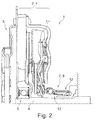
- Fig. 2
- eine zweite Ausführungsform eines Kraftfahrzeugantriebsstrangs in einer zur
Fig. 1 vergleichbaren Darstellungsweise, - Fig. 3
- eine dritte Ausführungsform eines erfindungsgemäßen Kraftfahrzeugantriebsstranges in einer zur
Fig. 1 vergleichbaren Darstellungsweise, - Fig. 4
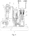
- eine vierte Ausführungsform eines erfindungsgemäßen Kraftfahrzeugantriebsstrangs in einer zur
Fig. 1 vergleichbaren Darstellungsweise, - Fig. 5
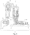
- eine fünfte Ausführungsform eines erfindungsgemäßen Kraftfahrzeugantriebsstrangs in einer zur
Fig. 1 vergleichbaren Darstellungsweise, - Fig. 6
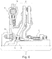
- eine sechste Ausführungsform eines erfindungsgemäßen Kraftfahrzeugantriebsstrangs in einer zur
Fig. 1 vergleichbaren Darstellungsweise, und - Fig. 7
- eine siebte Ausführungsform eines erfindungsgemäßen Kraftfahrzeugantriebsstrangs in einer zur
Fig. 1 vergleichbaren Darstellungsweise. - Die Figuren sind lediglich schematischer Natur und dienen nur dem Verständnis der Erfindung. Die gleichen Elemente sind mit denselben Bezugszeichen versehen. Einzelne Merkmale der Ausführungsbeispiele können untereinander ausgetauscht werden.
- In
Fig. 1 ist ein Kraftfahrzeugantriebsstrang 1 dargestellt. Er wirkt mit einem nicht dargestellten Antriebsaggregat zusammen und ist zum Weiterleiten, im eingekuppelten, also zugedrückten Zustand, an ein nicht dargestelltes Getriebe vorgesehen. Der Kraftfahrzeugantriebsstrang 1 weist eine Kupplung 2 auf, die benachbart zu einem Drehmomenteinleitorgan 3 angeordnet ist. Die Kupplung 2 ist als Einfachkupplung 4 ausgebildet, eben gerade nicht als Doppelkupplung, sie enthält also keine zwei konzentrisch zueinander angeordneten Kupplungen. Die Einfachkupplung 4 ist als zuzudrückende Kupplung 2, nämlich als "normally open"-Kupplung ausgebildet. - Die Einfachkupplung 4 stützt sich über ein Stützlager 5 auf einer Getriebeeingangswelle 6 ab. Jenes Stützlager 5 ist ein Schrägkugellager.
- Es ist ein Kupplungsaktor 7 eingesetzt, wobei in diesem Ausführungsbeispiel der Kupplungsaktor 7 als Stellteil 8 agiert. In Verbindung mit der dargestellten hebelübersetzten Kupplung wird so ein Übersetzungsverhältnis i<1 von Einrückkraft (ERK) zu Anpresskraft (APK) erreicht.
- Es ist eine Verschleißnachstellung 18 realisiert, die aber auch weglassbar ist. Es wird ein geführtes Einrücksystem 9 eingesetzt. Es wird ferner ein Hebelaktor 10 eingesetzt, der einen Faltenbalg 11 nutzt.
- In
Fig. 2 ist ein zweites Ausführungsbeispiel eines erfindungsgemäßen Kraftfahrzeugantriebsstrangs 1 im Ausschnitt dargestellt, wobei die Kupplung 2 wiederum als Einfachkupplung ausgebildet ist. Anders als in dem ersten Ausführungsbeispiel ist jedoch statt eines geführten Einrücksystems ein zentraler Kupplungseinrücker (CSC) 12 eingesetzt. Zwar ist wiederum eine Verschleißnachstelleinrichtung 18 vorgesehen, aber auch weglassbar. Die Aktorik setzt auf einen hydrostatischen Kupplungsaktor (HCA) 13 und ein nicht näher detailliertes "Powerpack". - Dazu ähnlich, ist in dem dritten Ausführungsbeispiel gemäß
Fig. 3 wiederum ein zentraler Kupplungseinrücker 12 in Verbindung mit einem hydrostatischem Kupplungsaktor 13 oder einem Powerpack eingesetzt. Statt eines an der Getriebeeingangswelle 6 angreifenden Stützlagers 5 wird ein abgewandeltes Wälzlager zwischen der Kupplung 2 und einem kurbelwellenfesten Bauteil 14 eingesetzt. Das kurbelwellenfeste Bauteil 14 ist mit einem Schwungrad 15 des Drehmomenteinleitorgans 3 verbunden oder mit diesem einteilig ausgeführt. - Das Ausgangsbeispiel gemäß
Fig. 4 ist dem ausFig. 3 ähnlich, doch wird eine ähnliche Aktorik wie in dem ersten Ausführungsbeispiel eingesetzt. Wie auch in dem dritten Ausführungsbeispiel, ist im vierten Ausführungsbeispiel keine Verschleißnachstelleinrichtung eingesetzt, aber einsetzbar. - Anders als in den Ausführungsbeispielen der
Fign. 1 bis 4 , wird in dem Ausführungsbeispiel gemäßFig. 5 ein weiteres Stützlager 5 am Kupplungsglockenboden eingesetzt, wobei jenes Stützlager auch als Deckellager 16 bezeichnet werden kann. - Die Umwandlung der Einrückkraft in Anpresskraft, eine Verschleißnachstellung und ein Betätigungs- bzw. Einrücksystem wie im zweiten Ausführungsbeispiel ist realisiert. Auch die Aktorik ist entsprechend.
- Das Ausführungsbeispiel gemäß
Fig. 6 zeigt in Abwandlung des Ausführungsbeispiels gemäßFig. 2 eine Anordnung mit einer direkt betätigten Kupplung. Ein Übersetzungsverhältnis von Anpresskraft zur Einrückkraft von ca. 1 wird realisiert. - In diesem Ausführungsbeispiel und in dem Ausführungsbeispiel gemäß
Fig. 7 ist vorzugsweise keine Verschleißnachstellung realisiert. In den Ausführungsbeispielen derFign. 1 bis 5 ist jedoch eine Verschleißnachstellung durch Verwendung einer Verschleißnachstelleinrichtung 17 realisiert. Die erfindungsgemäßen Kraftfahrzeugantriebsstränge 1 können sowohl mit, also auch ohne Verschleißnachstelleinrichtung 17 realisiert werden. - Das Ausführungsbeispiel gemäß
Fig. 7 entspricht dem Ausführungsbeispiel gemäßFig. 6 , doch ist auch dieses Ausführungsbeispiel, verglichen mit den ersten fünf Ausführungsbeispielen kostengünstiger, da ein Nachstellen über eine Hydraulik ermöglicht ist, also über längere Wege, und dadurch weniger Einrückbauteile enthält, also geringere Toleranzen nach sich zieht. Die beiden Varianten ermöglichen das Vermeiden von Rupfen und Klappern und weisen ein besseres Praxisverhalten und somit einen besseren Komfort auf. -
- 1
- Kraftfahrzeugantriebsstrang
- 2
- Kupplung
- 3
- Drehmomenteinleitorgan
- 4
- Einfachkupplung
- 5
- Stützlast
- 6
- Getriebeeingangswelle
- 7
- Kupplungsaktor
- 8
- Stellteil
- 9
- geführtes Einrücksystem
- 10
- Hebelaktor
- 11
- Faltenbalg
- 12
- zentraler Kupplungseinrücker
- 13
- HCA
- 14
- kurbelwellenfestes Bauteil
- 15
- Schwungrad
- 16
- Deckellager
- 17
- Verschleißnachstelleinrichtung
Claims (10)
- Kraftfahrzeugantriebsstrang (1), mit einem Antriebsaggregat und einem Getriebe sowie einer dazwischengeschalteten Kupplung (2), dadurch gekennzeichnet, dass die Kupplung (2) als zum Drehmomentübertragen zuzudrückende ("normally open") Einfachkupplung (4) ausgebildet ist.
- Kraftfahrzeugantriebsstrang (1) nach Anspruch 1, dadurch gekennzeichnet, dass die Kupplung (2) über zumindest ein Stützlager (5) axial positionsbestimmt auf einer Getriebeeingangswelle (6) und/oder einem Deckel und/oder einer Kurbelwelle und/oder einem kurbelwellenfesten Bauteil (14) gelagert ist.
- Kraftfahrzeugantriebsstrang (1) nach Anspruch 1 oder 2, dadurch gekennzeichnet, dass ein Kupplungsaktor (7) auf die Kupplung (2) einwirkt, der als direkt gedrückter Aktor mit einem Übersetzungsverhältnis von Anpresskraft zur Einrückkraft von ca. 1 ausgebildet ist oder als Aktor mit einem Übersetzungsverhältnis von Anpresskraft zur Einrückkraft von >1 ausgebildet ist.
- Kraftfahrzeugantriebsstrang (1) nach Anspruch 3, dadurch gekennzeichnet, dass der Kupplungsaktor (7) mit einem hebelartigen Blechbauteil, einer Hebelfeder und/oder einem Einzelhebel in radialer oder tangentialer Anordnung zum Erreichen des jeweiligen Übersetzungsverhältnisses in Wirkzusammenhang steht.
- Kraftfahrzeugantriebsstrang (1) nach einem der Ansprüche 1 bis 4, dadurch gekennzeichnet, dass eine Verschleißnachstelleinrichtung (17) integriert ist, die so ausgebildet ist, dass sie kraft- oder weggesteuert einen im Betrieb der Kupplung (2) auftretenden Verschleiß kompensiert.
- Kraftfahrzeugantriebsstrang (1) nach Anspruch 4 oder 5, dadurch gekennzeichnet, dass der Kupplungsaktor (7) als zentraler Kupplungseinrücker (12) (CSC) oder als geführtes Einrücksystem (9) ausgebildet ist.
- Kraftfahrzeugantriebsstrang (1) nach einem der Ansprüche 4 bis 6, dadurch gekennzeichnet, dass der Kupplungsaktor (7) einen Hebelaktor, einen hydrostatischen Aktor (HCA) (13) und/oder ein Powerpack einsetzt.
- Kraftfahrzeugantriebsstrang (1) nach einem der Ansprüche 1 bis 7, dadurch gekennzeichnet, dass das Getriebe als automatisches Schaltgetriebe (ASG) oder manuelles Handschaltgetriebe ausgebildet ist.
- Kraftfahrzeugantriebsstrang (1) nach einem der Ansprüche 1 bis 8, dadurch gekennzeichnet, dass die Kupplung (2) als Einscheibenkupplung oder Lamellenkupplung ausgebildet ist.
- Kraftfahrzeugantriebsstrang (1) nach einem der Ansprüche 1 bis 9, dadurch gekennzeichnet, dass die Kupplung (2) als nasse oder trockene Kupplung ausgebildet ist.
Applications Claiming Priority (1)
| Application Number | Priority Date | Filing Date | Title |
|---|---|---|---|
| DE102015209805 | 2015-05-28 |
Publications (3)
| Publication Number | Publication Date |
|---|---|
| EP3098470A2 true EP3098470A2 (de) | 2016-11-30 |
| EP3098470A3 EP3098470A3 (de) | 2017-01-11 |
| EP3098470B1 EP3098470B1 (de) | 2021-11-24 |
Family
ID=55808486
Family Applications (1)
| Application Number | Title | Priority Date | Filing Date |
|---|---|---|---|
| EP16166790.2A Active EP3098470B1 (de) | 2015-05-28 | 2016-04-25 | Kraftfahrzeugantriebsstrang mit zuzudrückender einfachkupplung |
Country Status (3)
| Country | Link |
|---|---|
| EP (1) | EP3098470B1 (de) |
| CN (1) | CN106183794A (de) |
| DE (1) | DE102016206928A1 (de) |
Families Citing this family (1)
| Publication number | Priority date | Publication date | Assignee | Title |
|---|---|---|---|---|
| DE102019105488B3 (de) * | 2019-03-05 | 2020-06-18 | Schaeffler Technologies AG & Co. KG | Anpressscheibe für eine Reibungskupplung |
Citations (1)
| Publication number | Priority date | Publication date | Assignee | Title |
|---|---|---|---|---|
| DE102014216277A1 (de) | 2013-09-30 | 2015-04-02 | Schaeffler Technologies Gmbh & Co. Kg | Reibungskupplungseinrichtung |
Family Cites Families (9)
| Publication number | Priority date | Publication date | Assignee | Title |
|---|---|---|---|---|
| GB830428A (en) * | 1957-03-08 | 1960-03-16 | Automotive Prod Co Ltd | Improvements in or relating to friction clutches |
| JP3250961B2 (ja) * | 1996-06-13 | 2002-01-28 | 株式会社エクセディ | 蓄圧式ハイブリッド車の動力伝達装置 |
| DE10235906A1 (de) * | 2002-08-06 | 2004-02-19 | Zf Sachs Ag | Drehmomentübertragungsvorrichtung in einem Kraftfahrzeug |
| DE102004009832A1 (de) * | 2003-03-03 | 2004-09-16 | Luk Lamellen Und Kupplungsbau Beteiligungs Kg | Ausrücksysteme |
| DE102004019513A1 (de) * | 2004-04-22 | 2005-11-10 | Zf Friedrichshafen Ag | Verfahren zum Betätigen eines automatisierten Kupplungssystems |
| DE102007031013A1 (de) * | 2006-07-20 | 2008-01-24 | Zf Friedrichshafen Ag | Kupplungsscheibe für eine Reibungskupplung |
| FR2950120B1 (fr) * | 2009-09-17 | 2014-03-14 | Valeo Embrayages | Dispositif d'embrayage a friction normalement ouvert equipe de moyens d'assistance au rappel des doigts du diaphragme vers leur position angulaire de repos. |
| FR2956172B1 (fr) * | 2010-02-05 | 2015-07-03 | Renault Sas | Mecanisme d'embrayage sec pour boite de vitesses de vehicule automobile |
| CN103711806B (zh) * | 2013-12-23 | 2016-05-04 | 福建省福工动力技术有限公司 | 用于混合动力汽车的常开式离合器 |
-
2016
- 2016-04-25 DE DE102016206928.4A patent/DE102016206928A1/de not_active Withdrawn
- 2016-04-25 EP EP16166790.2A patent/EP3098470B1/de active Active
- 2016-05-30 CN CN201610368122.5A patent/CN106183794A/zh active Pending
Patent Citations (1)
| Publication number | Priority date | Publication date | Assignee | Title |
|---|---|---|---|---|
| DE102014216277A1 (de) | 2013-09-30 | 2015-04-02 | Schaeffler Technologies Gmbh & Co. Kg | Reibungskupplungseinrichtung |
Also Published As
| Publication number | Publication date |
|---|---|
| DE102016206928A1 (de) | 2016-12-01 |
| EP3098470B1 (de) | 2021-11-24 |
| CN106183794A (zh) | 2016-12-07 |
| EP3098470A3 (de) | 2017-01-11 |
Similar Documents
| Publication | Publication Date | Title |
|---|---|---|
| EP3448705B1 (de) | Hybridmodul und antriebsanordnung für ein kraftfahrzeug | |
| EP1988302B1 (de) | Doppelkupplung | |
| EP3139053B1 (de) | Doppelkupplung mit stehendem kolben und verbesserten einrücklagern | |
| DE102014103914A1 (de) | Parksperrenanordnung für ein Kraftfahrzeuggetriebe | |
| WO2018054412A1 (de) | Betätigungssystem und kupplungseinrichtung für ein kraftfahrzeug | |
| DE102011015270A1 (de) | Doppelkupplung | |
| WO2018113839A1 (de) | Kupplungseinrichtung, hybridmodul und antriebsanordnung für ein kraftfahrzeug | |
| WO2011137889A1 (de) | Doppelkupplung | |
| DE102012206658A1 (de) | Doppelkupplung für Kraftfahrzeuge | |
| EP3704393B1 (de) | Mehrfachkupplungseinrichtung und hybridmodul für ein kraftfahrzeug | |
| DE102015202334A1 (de) | Zweimassenschwungrad mit integriertem Freilauf | |
| WO2010015228A1 (de) | Doppelkupplung | |
| EP1862688B1 (de) | Drehmomentübertragungsanordnung für den Antriebsstrang eines Fahrzeugs | |
| DE102020202139A1 (de) | Hybrid-Antriebsstrang für ein Kraftfahrzeug mit Trennelement | |
| WO2010149130A2 (de) | Doppelkupplung | |
| EP3752379A1 (de) | Hybridmodul und antriebsanordnung für ein kraftfahrzeug | |
| EP3098470B1 (de) | Kraftfahrzeugantriebsstrang mit zuzudrückender einfachkupplung | |
| DE102009046599A1 (de) | Reibungskupplung für ein Kraftfahrzeug mit einer Einrichtung zum Dämpfen von Axialschwingungen | |
| DE102021107964A1 (de) | Drehmomentübertragungseinrichtung | |
| EP3966058A1 (de) | Hybridmodul sowie antriebsanordnung für ein kraftfahrzeug | |
| EP2827479B1 (de) | Gezogene rotorintegrierte Trennkupplung für Hybridsysteme mit innenliegender Betätigung | |
| DE102014208889A1 (de) | Mehrteiliger Klemmfederring für ein Kupplungsaggregat | |
| DE102019117059A1 (de) | Hybridmodul sowie Antriebsanordnung für ein Kraftfahrzeug | |
| DE102020107768B4 (de) | Zentralausrückeranordnung | |
| EP3969769B1 (de) | Kupplungsvorrichtung, hybridmodul sowie antriebsanordnung für ein kraftfahrzeug |
Legal Events
| Date | Code | Title | Description |
|---|---|---|---|
| PUAI | Public reference made under article 153(3) epc to a published international application that has entered the european phase |
Free format text: ORIGINAL CODE: 0009012 |
|
| AK | Designated contracting states |
Kind code of ref document: A2 Designated state(s): AL AT BE BG CH CY CZ DE DK EE ES FI FR GB GR HR HU IE IS IT LI LT LU LV MC MK MT NL NO PL PT RO RS SE SI SK SM TR |
|
| AX | Request for extension of the european patent |
Extension state: BA ME |
|
| PUAL | Search report despatched |
Free format text: ORIGINAL CODE: 0009013 |
|
| AK | Designated contracting states |
Kind code of ref document: A3 Designated state(s): AL AT BE BG CH CY CZ DE DK EE ES FI FR GB GR HR HU IE IS IT LI LT LU LV MC MK MT NL NO PL PT RO RS SE SI SK SM TR |
|
| AX | Request for extension of the european patent |
Extension state: BA ME |
|
| RIC1 | Information provided on ipc code assigned before grant |
Ipc: F16D 13/71 20060101AFI20161208BHEP |
|
| STAA | Information on the status of an ep patent application or granted ep patent |
Free format text: STATUS: REQUEST FOR EXAMINATION WAS MADE |
|
| 17P | Request for examination filed |
Effective date: 20170711 |
|
| RBV | Designated contracting states (corrected) |
Designated state(s): AL AT BE BG CH CY CZ DE DK EE ES FI FR GB GR HR HU IE IS IT LI LT LU LV MC MK MT NL NO PL PT RO RS SE SI SK SM TR |
|
| STAA | Information on the status of an ep patent application or granted ep patent |
Free format text: STATUS: EXAMINATION IS IN PROGRESS |
|
| 17Q | First examination report despatched |
Effective date: 20190516 |
|
| GRAP | Despatch of communication of intention to grant a patent |
Free format text: ORIGINAL CODE: EPIDOSNIGR1 |
|
| STAA | Information on the status of an ep patent application or granted ep patent |
Free format text: STATUS: GRANT OF PATENT IS INTENDED |
|
| INTG | Intention to grant announced |
Effective date: 20210730 |
|
| GRAS | Grant fee paid |
Free format text: ORIGINAL CODE: EPIDOSNIGR3 |
|
| GRAA | (expected) grant |
Free format text: ORIGINAL CODE: 0009210 |
|
| STAA | Information on the status of an ep patent application or granted ep patent |
Free format text: STATUS: THE PATENT HAS BEEN GRANTED |
|
| AK | Designated contracting states |
Kind code of ref document: B1 Designated state(s): AL AT BE BG CH CY CZ DE DK EE ES FI FR GB GR HR HU IE IS IT LI LT LU LV MC MK MT NL NO PL PT RO RS SE SI SK SM TR |
|
| REG | Reference to a national code |
Ref country code: GB Ref legal event code: FG4D Free format text: NOT ENGLISH |
|
| REG | Reference to a national code |
Ref country code: AT Ref legal event code: REF Ref document number: 1450084 Country of ref document: AT Kind code of ref document: T Effective date: 20211215 |
|
| REG | Reference to a national code |
Ref country code: DE Ref legal event code: R096 Ref document number: 502016014177 Country of ref document: DE |
|
| REG | Reference to a national code |
Ref country code: IE Ref legal event code: FG4D Free format text: LANGUAGE OF EP DOCUMENT: GERMAN |
|
| REG | Reference to a national code |
Ref country code: LT Ref legal event code: MG9D |
|
| REG | Reference to a national code |
Ref country code: NL Ref legal event code: MP Effective date: 20211124 |
|
| PG25 | Lapsed in a contracting state [announced via postgrant information from national office to epo] |
Ref country code: RS Free format text: LAPSE BECAUSE OF FAILURE TO SUBMIT A TRANSLATION OF THE DESCRIPTION OR TO PAY THE FEE WITHIN THE PRESCRIBED TIME-LIMIT Effective date: 20211124 Ref country code: LT Free format text: LAPSE BECAUSE OF FAILURE TO SUBMIT A TRANSLATION OF THE DESCRIPTION OR TO PAY THE FEE WITHIN THE PRESCRIBED TIME-LIMIT Effective date: 20211124 Ref country code: FI Free format text: LAPSE BECAUSE OF FAILURE TO SUBMIT A TRANSLATION OF THE DESCRIPTION OR TO PAY THE FEE WITHIN THE PRESCRIBED TIME-LIMIT Effective date: 20211124 Ref country code: BG Free format text: LAPSE BECAUSE OF FAILURE TO SUBMIT A TRANSLATION OF THE DESCRIPTION OR TO PAY THE FEE WITHIN THE PRESCRIBED TIME-LIMIT Effective date: 20220224 |
|
| PG25 | Lapsed in a contracting state [announced via postgrant information from national office to epo] |
Ref country code: IS Free format text: LAPSE BECAUSE OF FAILURE TO SUBMIT A TRANSLATION OF THE DESCRIPTION OR TO PAY THE FEE WITHIN THE PRESCRIBED TIME-LIMIT Effective date: 20220324 Ref country code: SE Free format text: LAPSE BECAUSE OF FAILURE TO SUBMIT A TRANSLATION OF THE DESCRIPTION OR TO PAY THE FEE WITHIN THE PRESCRIBED TIME-LIMIT Effective date: 20211124 Ref country code: PT Free format text: LAPSE BECAUSE OF FAILURE TO SUBMIT A TRANSLATION OF THE DESCRIPTION OR TO PAY THE FEE WITHIN THE PRESCRIBED TIME-LIMIT Effective date: 20220324 Ref country code: PL Free format text: LAPSE BECAUSE OF FAILURE TO SUBMIT A TRANSLATION OF THE DESCRIPTION OR TO PAY THE FEE WITHIN THE PRESCRIBED TIME-LIMIT Effective date: 20211124 Ref country code: NO Free format text: LAPSE BECAUSE OF FAILURE TO SUBMIT A TRANSLATION OF THE DESCRIPTION OR TO PAY THE FEE WITHIN THE PRESCRIBED TIME-LIMIT Effective date: 20220224 Ref country code: NL Free format text: LAPSE BECAUSE OF FAILURE TO SUBMIT A TRANSLATION OF THE DESCRIPTION OR TO PAY THE FEE WITHIN THE PRESCRIBED TIME-LIMIT Effective date: 20211124 Ref country code: LV Free format text: LAPSE BECAUSE OF FAILURE TO SUBMIT A TRANSLATION OF THE DESCRIPTION OR TO PAY THE FEE WITHIN THE PRESCRIBED TIME-LIMIT Effective date: 20211124 Ref country code: HR Free format text: LAPSE BECAUSE OF FAILURE TO SUBMIT A TRANSLATION OF THE DESCRIPTION OR TO PAY THE FEE WITHIN THE PRESCRIBED TIME-LIMIT Effective date: 20211124 Ref country code: GR Free format text: LAPSE BECAUSE OF FAILURE TO SUBMIT A TRANSLATION OF THE DESCRIPTION OR TO PAY THE FEE WITHIN THE PRESCRIBED TIME-LIMIT Effective date: 20220225 Ref country code: ES Free format text: LAPSE BECAUSE OF FAILURE TO SUBMIT A TRANSLATION OF THE DESCRIPTION OR TO PAY THE FEE WITHIN THE PRESCRIBED TIME-LIMIT Effective date: 20211124 |
|
| PG25 | Lapsed in a contracting state [announced via postgrant information from national office to epo] |
Ref country code: SM Free format text: LAPSE BECAUSE OF FAILURE TO SUBMIT A TRANSLATION OF THE DESCRIPTION OR TO PAY THE FEE WITHIN THE PRESCRIBED TIME-LIMIT Effective date: 20211124 Ref country code: SK Free format text: LAPSE BECAUSE OF FAILURE TO SUBMIT A TRANSLATION OF THE DESCRIPTION OR TO PAY THE FEE WITHIN THE PRESCRIBED TIME-LIMIT Effective date: 20211124 Ref country code: RO Free format text: LAPSE BECAUSE OF FAILURE TO SUBMIT A TRANSLATION OF THE DESCRIPTION OR TO PAY THE FEE WITHIN THE PRESCRIBED TIME-LIMIT Effective date: 20211124 Ref country code: EE Free format text: LAPSE BECAUSE OF FAILURE TO SUBMIT A TRANSLATION OF THE DESCRIPTION OR TO PAY THE FEE WITHIN THE PRESCRIBED TIME-LIMIT Effective date: 20211124 Ref country code: DK Free format text: LAPSE BECAUSE OF FAILURE TO SUBMIT A TRANSLATION OF THE DESCRIPTION OR TO PAY THE FEE WITHIN THE PRESCRIBED TIME-LIMIT Effective date: 20211124 Ref country code: CZ Free format text: LAPSE BECAUSE OF FAILURE TO SUBMIT A TRANSLATION OF THE DESCRIPTION OR TO PAY THE FEE WITHIN THE PRESCRIBED TIME-LIMIT Effective date: 20211124 |
|
| REG | Reference to a national code |
Ref country code: DE Ref legal event code: R097 Ref document number: 502016014177 Country of ref document: DE |
|
| PLBE | No opposition filed within time limit |
Free format text: ORIGINAL CODE: 0009261 |
|
| STAA | Information on the status of an ep patent application or granted ep patent |
Free format text: STATUS: NO OPPOSITION FILED WITHIN TIME LIMIT |
|
| PG25 | Lapsed in a contracting state [announced via postgrant information from national office to epo] |
Ref country code: AL Free format text: LAPSE BECAUSE OF FAILURE TO SUBMIT A TRANSLATION OF THE DESCRIPTION OR TO PAY THE FEE WITHIN THE PRESCRIBED TIME-LIMIT Effective date: 20211124 |
|
| 26N | No opposition filed |
Effective date: 20220825 |
|
| PG25 | Lapsed in a contracting state [announced via postgrant information from national office to epo] |
Ref country code: SI Free format text: LAPSE BECAUSE OF FAILURE TO SUBMIT A TRANSLATION OF THE DESCRIPTION OR TO PAY THE FEE WITHIN THE PRESCRIBED TIME-LIMIT Effective date: 20211124 |
|
| REG | Reference to a national code |
Ref country code: CH Ref legal event code: PL |
|
| GBPC | Gb: european patent ceased through non-payment of renewal fee |
Effective date: 20220425 |
|
| REG | Reference to a national code |
Ref country code: BE Ref legal event code: MM Effective date: 20220430 |
|
| PG25 | Lapsed in a contracting state [announced via postgrant information from national office to epo] |
Ref country code: MC Free format text: LAPSE BECAUSE OF FAILURE TO SUBMIT A TRANSLATION OF THE DESCRIPTION OR TO PAY THE FEE WITHIN THE PRESCRIBED TIME-LIMIT Effective date: 20211124 Ref country code: LU Free format text: LAPSE BECAUSE OF NON-PAYMENT OF DUE FEES Effective date: 20220425 Ref country code: LI Free format text: LAPSE BECAUSE OF NON-PAYMENT OF DUE FEES Effective date: 20220430 Ref country code: GB Free format text: LAPSE BECAUSE OF NON-PAYMENT OF DUE FEES Effective date: 20220425 Ref country code: CH Free format text: LAPSE BECAUSE OF NON-PAYMENT OF DUE FEES Effective date: 20220430 |
|
| PG25 | Lapsed in a contracting state [announced via postgrant information from national office to epo] |
Ref country code: BE Free format text: LAPSE BECAUSE OF NON-PAYMENT OF DUE FEES Effective date: 20220430 |
|
| PG25 | Lapsed in a contracting state [announced via postgrant information from national office to epo] |
Ref country code: IE Free format text: LAPSE BECAUSE OF NON-PAYMENT OF DUE FEES Effective date: 20220425 |
|
| PG25 | Lapsed in a contracting state [announced via postgrant information from national office to epo] |
Ref country code: IT Free format text: LAPSE BECAUSE OF FAILURE TO SUBMIT A TRANSLATION OF THE DESCRIPTION OR TO PAY THE FEE WITHIN THE PRESCRIBED TIME-LIMIT Effective date: 20211124 |
|
| REG | Reference to a national code |
Ref country code: AT Ref legal event code: MM01 Ref document number: 1450084 Country of ref document: AT Kind code of ref document: T Effective date: 20220425 |
|
| P01 | Opt-out of the competence of the unified patent court (upc) registered |
Effective date: 20230522 |
|
| PG25 | Lapsed in a contracting state [announced via postgrant information from national office to epo] |
Ref country code: AT Free format text: LAPSE BECAUSE OF NON-PAYMENT OF DUE FEES Effective date: 20220425 |
|
| PG25 | Lapsed in a contracting state [announced via postgrant information from national office to epo] |
Ref country code: HU Free format text: LAPSE BECAUSE OF FAILURE TO SUBMIT A TRANSLATION OF THE DESCRIPTION OR TO PAY THE FEE WITHIN THE PRESCRIBED TIME-LIMIT; INVALID AB INITIO Effective date: 20160425 |
|
| PG25 | Lapsed in a contracting state [announced via postgrant information from national office to epo] |
Ref country code: MK Free format text: LAPSE BECAUSE OF FAILURE TO SUBMIT A TRANSLATION OF THE DESCRIPTION OR TO PAY THE FEE WITHIN THE PRESCRIBED TIME-LIMIT Effective date: 20211124 Ref country code: CY Free format text: LAPSE BECAUSE OF FAILURE TO SUBMIT A TRANSLATION OF THE DESCRIPTION OR TO PAY THE FEE WITHIN THE PRESCRIBED TIME-LIMIT Effective date: 20211124 |
|
| PG25 | Lapsed in a contracting state [announced via postgrant information from national office to epo] |
Ref country code: MT Free format text: LAPSE BECAUSE OF FAILURE TO SUBMIT A TRANSLATION OF THE DESCRIPTION OR TO PAY THE FEE WITHIN THE PRESCRIBED TIME-LIMIT Effective date: 20211124 |
|
| PGFP | Annual fee paid to national office [announced via postgrant information from national office to epo] |
Ref country code: DE Payment date: 20250618 Year of fee payment: 10 |
|
| PGFP | Annual fee paid to national office [announced via postgrant information from national office to epo] |
Ref country code: FR Payment date: 20250425 Year of fee payment: 10 |
|
| PG25 | Lapsed in a contracting state [announced via postgrant information from national office to epo] |
Ref country code: TR Free format text: LAPSE BECAUSE OF FAILURE TO SUBMIT A TRANSLATION OF THE DESCRIPTION OR TO PAY THE FEE WITHIN THE PRESCRIBED TIME-LIMIT Effective date: 20211124 |