EP3098413B1 - Atténuateur acoustique d'amortissement de vibrations de pression dans un système d'échappement d'un moteur - Google Patents
Atténuateur acoustique d'amortissement de vibrations de pression dans un système d'échappement d'un moteur Download PDFInfo
- Publication number
- EP3098413B1 EP3098413B1 EP16166298.6A EP16166298A EP3098413B1 EP 3098413 B1 EP3098413 B1 EP 3098413B1 EP 16166298 A EP16166298 A EP 16166298A EP 3098413 B1 EP3098413 B1 EP 3098413B1
- Authority
- EP
- European Patent Office
- Prior art keywords
- gas
- attenuator
- gas passage
- resonator
- acoustic attenuator
- Prior art date
- Legal status (The legal status is an assumption and is not a legal conclusion. Google has not performed a legal analysis and makes no representation as to the accuracy of the status listed.)
- Active
Links
Images


Classifications
-
- F—MECHANICAL ENGINEERING; LIGHTING; HEATING; WEAPONS; BLASTING
- F01—MACHINES OR ENGINES IN GENERAL; ENGINE PLANTS IN GENERAL; STEAM ENGINES
- F01N—GAS-FLOW SILENCERS OR EXHAUST APPARATUS FOR MACHINES OR ENGINES IN GENERAL; GAS-FLOW SILENCERS OR EXHAUST APPARATUS FOR INTERNAL-COMBUSTION ENGINES
- F01N1/00—Silencing apparatus characterised by method of silencing
- F01N1/02—Silencing apparatus characterised by method of silencing by using resonance
- F01N1/023—Helmholtz resonators
-
- F—MECHANICAL ENGINEERING; LIGHTING; HEATING; WEAPONS; BLASTING
- F01—MACHINES OR ENGINES IN GENERAL; ENGINE PLANTS IN GENERAL; STEAM ENGINES
- F01N—GAS-FLOW SILENCERS OR EXHAUST APPARATUS FOR MACHINES OR ENGINES IN GENERAL; GAS-FLOW SILENCERS OR EXHAUST APPARATUS FOR INTERNAL-COMBUSTION ENGINES
- F01N1/00—Silencing apparatus characterised by method of silencing
- F01N1/02—Silencing apparatus characterised by method of silencing by using resonance
- F01N1/026—Annular resonance chambers arranged concentrically to an exhaust passage and communicating with it, e.g. via at least one opening in the exhaust passage
-
- F—MECHANICAL ENGINEERING; LIGHTING; HEATING; WEAPONS; BLASTING
- F01—MACHINES OR ENGINES IN GENERAL; ENGINE PLANTS IN GENERAL; STEAM ENGINES
- F01N—GAS-FLOW SILENCERS OR EXHAUST APPARATUS FOR MACHINES OR ENGINES IN GENERAL; GAS-FLOW SILENCERS OR EXHAUST APPARATUS FOR INTERNAL-COMBUSTION ENGINES
- F01N13/00—Exhaust or silencing apparatus characterised by constructional features
- F01N13/02—Exhaust or silencing apparatus characterised by constructional features having two or more separate silencers in series
-
- F—MECHANICAL ENGINEERING; LIGHTING; HEATING; WEAPONS; BLASTING
- F01—MACHINES OR ENGINES IN GENERAL; ENGINE PLANTS IN GENERAL; STEAM ENGINES
- F01N—GAS-FLOW SILENCERS OR EXHAUST APPARATUS FOR MACHINES OR ENGINES IN GENERAL; GAS-FLOW SILENCERS OR EXHAUST APPARATUS FOR INTERNAL-COMBUSTION ENGINES
- F01N2340/00—Dimensional characteristics of the exhaust system, e.g. length, diameter or volume of the exhaust apparatus; Spatial arrangements of exhaust apparatuses
- F01N2340/02—Distance of the exhaust apparatus to the engine or between two exhaust apparatuses
-
- F—MECHANICAL ENGINEERING; LIGHTING; HEATING; WEAPONS; BLASTING
- F01—MACHINES OR ENGINES IN GENERAL; ENGINE PLANTS IN GENERAL; STEAM ENGINES
- F01N—GAS-FLOW SILENCERS OR EXHAUST APPARATUS FOR MACHINES OR ENGINES IN GENERAL; GAS-FLOW SILENCERS OR EXHAUST APPARATUS FOR INTERNAL-COMBUSTION ENGINES
- F01N2490/00—Structure, disposition or shape of gas-chambers
- F01N2490/10—Two or more expansion chambers in parallel
-
- F—MECHANICAL ENGINEERING; LIGHTING; HEATING; WEAPONS; BLASTING
- F01—MACHINES OR ENGINES IN GENERAL; ENGINE PLANTS IN GENERAL; STEAM ENGINES
- F01N—GAS-FLOW SILENCERS OR EXHAUST APPARATUS FOR MACHINES OR ENGINES IN GENERAL; GAS-FLOW SILENCERS OR EXHAUST APPARATUS FOR INTERNAL-COMBUSTION ENGINES
- F01N2490/00—Structure, disposition or shape of gas-chambers
- F01N2490/15—Plurality of resonance or dead chambers
- F01N2490/155—Plurality of resonance or dead chambers being disposed one after the other in flow direction
-
- F—MECHANICAL ENGINEERING; LIGHTING; HEATING; WEAPONS; BLASTING
- F01—MACHINES OR ENGINES IN GENERAL; ENGINE PLANTS IN GENERAL; STEAM ENGINES
- F01N—GAS-FLOW SILENCERS OR EXHAUST APPARATUS FOR MACHINES OR ENGINES IN GENERAL; GAS-FLOW SILENCERS OR EXHAUST APPARATUS FOR INTERNAL-COMBUSTION ENGINES
- F01N2590/00—Exhaust or silencing apparatus adapted to particular use, e.g. for military applications, airplanes, submarines
- F01N2590/10—Exhaust or silencing apparatus adapted to particular use, e.g. for military applications, airplanes, submarines for stationary applications
Definitions
- the invention relates to an acoustic attenuator for damping pressure vibrations in an exhaust system of an engine, the acoustic attenuator comprising a body which is provided with a gas inlet and a gas outlet at opposite ends thereof, and a gas passage duct arranged between the inlet and the outlet inside the body, where in the body encloses a first resonator chamber and a second resonator chamber according to the preamble of claim 1.
- Invention relates also an acoustic attenuation system using the attenuators in an exhaust system of an engine.
- Noise occurring in the exhaust system can be reduced by using different types of damping techniques.
- one attenuator type is a reactive attenuator and another is a resistive attenuator.
- Reactive attenuators generally consist of a duct section or alike that interconnects with a number of larger chambers.
- the noise reduction mechanism of reactive attenuators is that the area discontinuity provides an impedance mismatch for the noise wave traveling along the duct. This impedance mismatch results in a reflection of part of the noise wave back toward the source or back and forth among the chambers.
- the reflective effect of the silencer chambers and ducts (typically referred to as resonators) essentially prevents some noise wave elements from being transmitted past the silencer.
- the reactive silencers are more effective at lower frequencies than at high frequencies, and are most widely used to attenuate the exhaust noise of internal combustion engines.
- WO 2014/076355 A1 discloses an exhaust gas noise attenuator unit comprising at least two reactive attenuation chambers.
- a first attenuation chamber of the at least two attenuation chambers is arranged in flow connection with the duct section at a first location in longitudinal direction and a second attenuation chamber of the at least two attenuation chambers is arranged in flow connection with the duct section at a second location in longitudinal direction.
- WO 2005/064127 A1 discloses a sound reduction system for reducing noise from a high power combustion engine.
- the sound reduction system comprises an element comprising a first reactive part, a resistive part and a second reactive part.
- the attenuation effect of the element in the low frequencies is mainly achieved by the reactive parts.
- the attenuating effect in the high frequency area of each element is mainly achieved by the resistive part.
- the resistive part contributes also to the attenuating effect in the low frequency area as a reflective attenuator.
- US 2010/0270103 A1 discloses a muffler for reducing the sounds of combustion gases exhausted from an internal combustion engine including an elongated fluid passage extending between an inlet and an outlet such that the outlet is in fluid communication with the inlet.
- the muffler further including an outer tank surrounding the passage and a tubular connector having a first end in fluid connection with the passage and a second end in fluid connection with the tank such that the connector produces a fluid connection between the passage and the tank.
- the connectors having a perforated resistance plate to restrict the fluid flow between said passage and said sound chamber thereby reducing the severity of the sound or fluid pulses entering and exiting said sound chamber, perforations in said perforated plate forming an open portion of said plate and said open portion being less than 60 percent.
- US 3434565 A discloses an exhaust gas muffler comprising an elongated tubular casing having an inlet at one end and an outlet at the other end, a plurality of transverse partitions extending across the width of the casing and subdividing it into a plurality of chambers, means in the casing providing a gas flow passage connecting said inlet and outlet and including a conduit extending through a pair of chambers, the wall of said conduit being inperforate in the first of said chambers and having a patch of louvers opening into the second of said chambers so that said second chamber acts to attenuate medium to high frequency sounds.
- tuning tube having first and second portions extending at substantially a right angle to each other, said tuning tube first portion being secured to and opening into said conduit in said second chamber at a location upstream of said louver patch and said first portion extending at substantially a right angle to said conduit, said tuning tube second portion extending in a downstream direction and through a partition and opening into said first chamber, the part of said tuning tube in said second chamber being imperforate, said tuning tube and said first chamber being acoustically interrelated to provide a Helmholtz resonator for silencing a predetermined frequency, lower than that attenuated by said second chamber.
- US 2580564 A discloses a silencer for attenuating sound waves in a stream of moving gases.
- a casing having end walls provided with aligned openings, nipples extending through said openings and secured to the respective end walls, conduit means within said casing providing a passage between said nipples and including a section of smaller diameter than said casing and having a multiplicity of longitudinally distributed openings affording communication between the interior of the conduit-section and the space surrounding it, one of said nipples being an integral length of tubing having portions of different diameters separated by an annular shoulder located inwardly of the adjacent end wall, the smaller diameter nipple-portion being located outwardly of the larger diameter portion and closely embracing said conduit-section, and the larger diameter nipple-portion extending axially along said conduit-section and in radially spaced relation thereto to form an annular passage, at least some of said openings in the conduit section lying within the axial extent of the larger diameter nipple-portion,
- US 2007051556 A1 discloses an exhaust system which comprises a muffler and a Helmholtz resonator.
- the muffler comprises an exhaust inlet aperture for receiving exhaust gas into the muffler, an exhaust outlet aperture for discharging exhaust gas from the muffler, and a resonator aperture.
- the Helmholtz resonator is at least partially external to the muffler and in acoustic communication with the resonator aperture.
- US 2297046 A discloses device preventing the formation of shock excited standing waves in pipes, chambers and the like and the treatment of such pipes, conduits or chambers, in such a manner as to render them acoustically dead to shock excitation; so that gas slugs of even great intensity do not create a set of new noises.
- the document is concerned not with the attenuation of noises as in the ordinary silencing system, but rather with the treatment of the gas conducting system so that it will not itself create sound waves due to shock excitation by a gas pulse or other disturbance which in itself may be soundless.
- US 5245140 A discloses a muffler including a high frequency chamber, a first exhaust pipe connected between an engine and the high frequency chamber, a second exhaust pipe disposed within said high frequency, an intermediate frequency chamber connected with the other end of the second exhaust chamber, a third exhaust pipe disposed within the intermediate frequency chamber, a low frequency chamber connected with the other end of the third exhaust pipe, and a tubular pipe disposed within the low frequency chamber, whereby the noise will be effectively suppressed without decreasing the flow rate of the exhaust gas and the output power of the engine.
- An object of the invention is to provide an acoustic attenuator which provides efficient attenuation of noise but still allowing a space saving installation in connection with an internal combustion engine exhaust gas system.
- an acoustic attenuator for damping pressure vibrations in an exhaust system of an engine, the acoustic attenuator comprising a body which is provided with a gas inlet and a gas outlet at opposite ends thereof, and a gas passage duct arranged between the inlet and the outlet inside the body, where in the body encloses a first resonator chamber and a second resonator chamber.
- the gas passage duct is provided with an opening located in longitudinal direction between the two intermediate walls and a space bordered by the sleeve part and the intermediate walls together with the opening in the gas passage duct forms a common connection inlet communicating with the first and the second resonator chambers.
- the resonator chambers are arranged to extend from the common inlet towards the opposite ends of the body.
- the acoustic attenuator according to the invention reduces noise propagation from an internal combustion piston engine into the exhaust system by means of two resonators integrated into the same body.
- the two resonators are dimensioned so as to produce attenuation at a broader frequency band not obtainable with singular element.
- the improvement relates to resonator space separation of two resonators and utilization of common, singular connection inlet for both chambers.
- the gas passage duct is formed of a straight gas duct and the resonator chambers are arranged annularly around the duct, wherein the attenuator comprises two longitudinally spaced intermediate walls radially extending from the gas passage duct to a sleeve part of the body and wherein the common inlet is arranged longitudinally between the intermediate walls.
- the structure is very versatile for adjusting its properties by only simple changes in the construction, such as changing the diameter and/or length of the sleeve part, and/or changing the position(s) of the intermediate wall(s).
- the attenuator the resonator chambers are connected with the common inlet via ports arranged to, and supported by the intermediate walls.
- the gas passage duct is formed of a straight gas duct and the resonator chambers are arranged annularly around the duct, wherein the attenuator comprises two longitudinally spaced intermediate walls radially extending from the gas passage duct to a sleeve part of the body and wherein the common inlet is arranged longitudinally between the intermediate walls and in the attenuator the resonator chambers are connected with the common inlet via ports arranged to, and supported by the intermediate walls.
- the gas passage duct is directed parallel with a longitudinal axis of the body and the ports are arranged parallel with the longitudinal axis of the body.
- the port is a tubular member supported by the intermediate wall.
- the attenuator comprises only two intermediate walls and two resonator chambers.
- the gas passage duct between the gas inlet and the gas outlet is provided with a solid, gas impermeable wall, which wall has an opening arranged between the intermediate walls.
- the ports and the resonator chambers are arranged such that no gas transmission may take place directly from one resonator chamber to another resonator chamber via a single port.
- An acoustic attenuation system comprises two acoustic attenuators for damping pressure vibrations in an exhaust system of an engine, in which each of the acoustic attenuator comprising a body which is provided with a gas inlet and a gas outlet at opposite ends thereof, and a gas passage duct arranged between the inlet and the outlet inside the body, where in the body encloses a first resonator chamber and a second resonator chamber, and further the body is provided with a common inlet communicating with the first and the second resonator chambers and the resonator chambers are arranged to extend from the common inlet towards the opposite ends of the body.
- the gas passage duct has a predetermined length between the common inlet for the first and the second acoustic attenuators in the system.
- the acoustic attenuators may be coupled one after the other in the exhaust system of an internal combustion engine such that the distance between the common inlet for the first and the second acoustic attenuators is determined so as to control acoustic wave phase difference between the acoustic attenuators.
- the resonator chambers are arranged such that the first resonator chamber of the first attenuator is tuned to attenuate a first frequency and the second resonator chamber of the first attenuator is tuned to attenuate a second frequency, and the first resonator chamber of the second attenuator is tuned to attenuate a third frequency and the second resonator chamber of the second attenuator is tuned to attenuate a fourth frequency, and resonator chambers are tuned to attenuate different frequencies and that two of the tuning frequencies closest to each other are arranged obtainable from separate acoustic attenuators.
- the resonator chambers are arranged such that the first resonator chamber of the first attenuator is tuned to attenuate a first frequency and the second resonator chamber of the first attenuator is tuned to attenuate a second frequency, and the first resonator chamber of the second attenuator is tuned to attenuate a third frequency and the second resonator chamber of the second attenuator is tuned to attenuate a fourth frequency, and the tuning frequencies are selected so that the third frequency > the second frequency > the fourth frequency > the first frequency.
- the acoustic attenuators are dimensioned and spatially separated so as to produce attenuation at a broader frequency band than obtainable with singular element.
- the attenuation is obtained by controlling acoustic wave phase difference between distributed elements by spatial and frequency separation.
- the obtained attenuation capacity is of higher amplitude and at broader frequency range than that is previously obtained and utilized in such applications.
- the attenuator is such that it is possible to be installed close to the noise source, i.e. the engine thus reducing engine's acoustic or noise radiation and thus effecting on mechanical constructions of exhaust gas system due to generally lower vibration levels.
- the attenuator according to the invention requires generally only a small space.
- the attenuator provides also a reduced back-pressure of exhaust system due to straight-thru-flow design as compared to previous singular units, resulting in higher engine or power plant system efficiency and lower emissions.
- the attenuator according to the invention may be easily installed to an existing plant simply by cutting the existing exhaust duct to install the intermediate walls provided with the ports, sleeve part and its end-plates.
- the attenuator provides also an efficient attenuation of low frequency noise, characteristic to reciprocating internal combustion engine, at broader frequency scale.
- the attenuator provides also an efficient means of modularization of the construction and utilization of similar parts with increased manufacturability.
- Figure 1 depicts schematically an acoustic attenuator 10 according to an embodiment of the invention.
- the attenuator is adapted to attenuate exhaust gas noise of an internal combustion piston engine, and in the figure 1 the attenuator is arranged to an exhaust gas system 12 of an internal combustion piston engine 14.
- the acoustic attenuator comprises a body 16 which is provided with an inlet 18 and an outlet 20 for the exhaust gas to enter and exit the acoustic attenuator.
- the body 16 is generally an elongated structure which is rotationally symmetrical in respect to its central axis 22.
- the inlet 18 and the outlet 20 are arranged at opposite ends of the body 16, on the central axis 22.
- the inlet 18 and the outlet are of equal cross sectional area (diameter when being tubular) and the inlet and the outlet are connected with each other by a gas passage duct 24 extending through the body 16 along the central axis 22.
- the gas passage is a gas passage duct arranged its centre line to coincide with the central axis 22 of the body 16.
- the body 16 is provided with a sleeve part 26 enclosing the gas passage duct 24 over a length in the direction of the central axis 22.
- a sleeve part 26 enclosing the gas passage duct 24 over a length in the direction of the central axis 22.
- the cross sectional area of the sleeve part 26 is greater than the cross sectional area of the gas passage duct. Specifically when the attenuator is of circular cross section, the diameter of the sleeve part 26 is greater than the diameter of the gas passage duct 24 and the sleeve part and the gas passage duct are arranged coaxially.
- the body 16 is further provided with two intermediate walls 30, 30'.
- the intermediate walls 30,30' are arranged to extend radially from the gas passage duct 24 to the sleeve part 26 and circumscribe the gas passage duct 24 forming a gas tight wall to the annular gap between the sleeve part 26 and the gas passage duct.
- the intermediate wall is an annular plate- or flange-like structure closing the gap between the sleeve part 26 and the gas passage duct.
- the intermediate walls 30, 30' are arranged at a distance from each other in the longitudinal direction, i.e. in the direction of the central axis 22.
- the intermediate walls act also as a support structure of the body part 16.
- the space bordered by the sleeve part 26, the intermediate walls 30, 30' together with the opening 32 in the gas passage duct 24 forms a common inlet 34 for the gas passage duct such that the gas passage duct is in fluid communication with the first 36 and the second 38 resonator chamber via the common inlet 34 in the body.
- the wall of the gas passage duct 24 between the intermediate walls is not essential to the acoustic performance,
- the resonator chambers 36,38 are arranged to extend in the longitudinal direction from the common inlet towards the opposite ends of the body.
- the gas passage duct 24 between the gas inlet 18 and the gas outlet 20 is provided with a solid, gas impermeable wall, which wall has its only opening 32 arranged between the intermediate walls 30, 30'.
- the attenuator is provided with at least one port 40 which are arranged in, and supported by each intermediate wall 30,30' which port opens a communication between the resonator chamber 36,38 and the common inlet 34, i.e. the common inlet 34 is arranged in fluid communication with the resonator chamber 36,38 via the port 40.
- the ports 40 are tubular members having a central axis 42.
- the ports 40 and their central axes 42 are arranged parallel with the longitudinal axis of the body 16.
- the diameter and length of the port tube 40 is dimensioned individually based on the desired attenuation effect of the attenuator. In the attenuator of the invention the precise tuning is straightforward by changing the dimensions of the tubular port.
- the ports and the resonator chambers are arranged such that no gas transmission may take place directly from one resonator chamber 36 to another resonator chamber 38 via a single port. This way the operation of a single resonator chamber directed effected be the operation of the other resonator chamber and the tuning is more accurate and straightforward.
- the distance between the intermediate walls is dimensioned to suit manufacturing process.
- the minimum distance is defined by wave motion physics to allow efficient connection from main duct into chambers via the tubular ports.
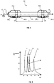
- Figures 2 and 3 depicts the cross sectional views II-II and III-III in the Figure 1 .
- the opening 32 in the gas passage duct 24 is formed by removing a segment 42 from the wall of the gas passage duct.
- the segment is arranged such that there is a solid wall portion of the gas passage duct 24 extending over the distance between the intermediate walls 30, 30' circumscribing or covering partially the gas passage duct in circumferential direction.
- the solid wall portion 44 is an optional feature which has a benefit of closing out a stagnant gas volume between the intermediate walls, to reduce gas accumulation. However, this is not essential for acoustic performance of the attenuator. Additionally the attenuator 10 may be provided with a closing plate 45 extending radially between the solid wall portion and the sleeve part 26 of the body 16, and extending longitudinally between the intermediate walls 30,30'. This is shown with dotted lines in the figures indicating the optional nature of the feature
- Figure 4 shows an acoustic attenuation system 100 comprising two acoustic attenuator 10.1,10.2 as is shown in the Figures 1 to 3 .
- the acoustic attenuators 10.1,10.2 are coupled one after the other in the exhaust system 12 of an engine such that there is a predetermined distance L of the gas passage duct 24 between the common inlet 34 for the first and the second acoustic attenuators in the system 100.
- the attenuators 10.1,10.2 are dimensioned and longitudinally separated so as to produce attenuation at a broader frequency band than obtainable with singular element.
- the attenuation by the acoustic attenuators 10.1,10.2 coupled one after the other in series in the gas passage duct 24 is obtained by controlling acoustic wave phase difference between distributed elements by spatial and frequency separation.
- the obtained attenuation capacity is of higher amplitude and at broader frequency range than that is previously obtained and utilized in such applications.
- the attenuators 10.1, 10.2 are each provided with two resonator chambers 36.1,38.1 ;36.2,38.2 as is disclosed in the Figure 1 ,
- the chambers are tuned to attenuate noise i.e. vibration in the following manner.
- the first resonator chamber 36.1 of the first attenuator 10.1 is tuned to attenuate as a center frequency a first frequency F1 and the second resonator chamber 38.1 of the first attenuator 10.1 is tuned to attenuate as a center frequency a second frequency F2, and respectively the first resonator chamber 36.2 of the second attenuator 10.2 is tuned to attenuate as a center frequency a third frequency F3 and the second resonator chamber 38.2 of the second attenuator 10.2 is tuned to attenuate as a center frequency a fourth frequency F4,
- the tuning frequencies are selected so that the third frequency F3 > the second frequency F2 > the fourth frequency F4 > the first frequency F1.
- the attenuators are utilized in optimized manner.
- the frequency means a certain range having it attenuation performance above a certain limit.
- the resonator chambers are arranged in the following order: the first resonator chamber 36.1 of the first attenuator 10.1, the second resonator chamber 38.1 of the first attenuator 10.1, the first resonator chamber 36.2 of the second attenuator 10.2 and the second resonator chamber 38.2 of the second attenuator 10.2.
- the transmission loss is defined as the difference between the power incident on the acoustic attenuator and that transmitted downstream from the attenuator into an anechoic termination.
- There are four peaks of transmission loss which represent the center tuning F1 of the first resonator chamber 36.1 of the first acoustic attenuator, the center tuning F4 of the second resonator chamber 38.2 of the second acoustic attenuator, the center tuning F2 of the second resonator chamber 36.2 of the first acoustic attenuator, and the center tuning F3 of the first resonator chamber 38.1 of the second acoustic attenuator.
- the resonator chambers are tuned to attenuate different frequencies and the frequencies are selected so that two of the tuning frequencies closest to each other are arranged in connection with or obtainable from separate acoustic attenuators 10.1,10.2.
- the system is dimensioned so that the distance between the common inlet for the first and the second acoustic attenuators is determined using the formula wherein
Landscapes
- Engineering & Computer Science (AREA)
- Chemical & Material Sciences (AREA)
- Combustion & Propulsion (AREA)
- Mechanical Engineering (AREA)
- General Engineering & Computer Science (AREA)
- Exhaust Silencers (AREA)
Claims (10)
- Atténuateur acoustique (10) destiné à l'amortissement des vibrations de pression dans un système d'échappement d'un moteur, l'atténuateur acoustique comprenant un corps (16) qui est doté d'une entrée de gaz (18) et d'une sortie de gaz (20) au niveau des extrémités opposées de celui-ci, et d'une conduite de passage de gaz (24) agencée entre l'entrée et la sortie à l'intérieur du corps, dans lequel le corps comprend une première chambre de résonateur (36) et une seconde chambre de résonateur (38), et le corps comprend deux parois intermédiaires espacées de manière longitudinale (30, 30') s'étendant de manière radiale depuis la conduite de passage de gaz (24) en direction d'une partie de manche (26) du corps (16), caractérisé en ce que
la conduite de passage de gaz (24) est dotée d'une ouverture (32) située dans une direction longitudinale entre les deux parois intermédiaires (30, 30') et d'un espace délimité par la partie de manche (26) et les parois intermédiaires (30, 30') ensemble avec l'ouverture (32) dans la conduite de passage de gaz (24) forment une entrée de connexion commune (34) communiquant avec la première et la seconde chambres de résonateur (36, 38),
et les chambres de résonateur (36, 38) sont agencées pour s'étendre à partir de l'entrée commune (34) en direction des extrémités opposées (25) du corps (16). - Atténuateur acoustique (10) selon la revendication 1, caractérisé en ce que l'espace délimité par la partie de manche (26), les parois intermédiaires (30, 30') et la paroi de la conduite de passage de gaz (24), ensemble avec l'ouverture (32) dans la conduite de passage de gaz (24) forment l'entrée de connexion commune (34).
- Atténuateur acoustique (10) selon la revendication 1, caractérisé en ce que la conduite de passage de gaz (24) entre l'entrée de gaz (18) et la sortie de gaz (20) est dotée d'une paroi solide, imperméable aux gaz, qui possède une ouverture (32) agencée entre les parois intermédiaires (30, 30').
- Atténuateur acoustique (10) selon la revendication 1, caractérisé en ce que la conduite de passage de gaz (24) est une conduite de gaz linéaire et les chambres de résonateur (36, 38) sont agencées de manière annulaire autour de la conduite.
- Atténuateur acoustique (10) selon la revendication 1, caractérisé en ce que les chambres de résonateur sont raccordées à l'entrée commune (34) par l'intermédiaire de ports (40).
- Atténuateur acoustique (10) selon la revendication 5, caractérisé en ce que les ports (4) sont agencés pour et supportés par les parois intermédiaires (30, 30').
- Atténuateur acoustique (10) selon la revendication 5, caractérisé en ce que la conduite de passage de gaz (24) est une conduite de gaz linéaire dirigée de manière parallèle à un axe longitudinal du corps (16) et les ports (40) sont agencés de manière parallèle à l'axe longitudinal du corps (16).
- Atténuateur acoustique (10) selon la revendication 6 ou la revendication 7, caractérisé en ce que le port (40) est un élément tubulaire supporté par la paroi intermédiaire.
- Atténuateur acoustique (10) selon la revendication 1, caractérisé en ce que l'atténuateur comprend uniquement deux parois intermédiaires (30, 30') et deux chambres de résonateur (36, 38).
- Atténuateur acoustique (10) selon la revendication 5, caractérisé en ce que les ports (40) et les chambres de résonateur (36, 38) sont agencés de sorte qu'aucune transmission de gaz puisse prendre lieu directement à partir d'une chambre de résonateur (36) vers une autre chambre de résonateur (38) par l'intermédiaire d'un port unique.
Applications Claiming Priority (1)
| Application Number | Priority Date | Filing Date | Title |
|---|---|---|---|
| PCT/FI2015/050359 WO2016189187A1 (fr) | 2015-05-25 | 2015-05-25 | Atténuateur acoustique pour amortissement des vibrations de pression dans un système d'échappement d'un moteur, système d'atténuation acoustique utilisant les atténuateurs et procédé d'amortissement des vibrations de pression dans un système d'échappement d'un moteur |
Publications (2)
| Publication Number | Publication Date |
|---|---|
| EP3098413A1 EP3098413A1 (fr) | 2016-11-30 |
| EP3098413B1 true EP3098413B1 (fr) | 2017-09-20 |
Family
ID=53404590
Family Applications (2)
| Application Number | Title | Priority Date | Filing Date |
|---|---|---|---|
| EP15729533.8A Active EP3303791B1 (fr) | 2015-05-25 | 2015-05-25 | Système d'atténuation acoustique utilisant des atténuateurs acoustique pour amortissement des vibrations de pression dans un système d'échappement d'un moteur |
| EP16166298.6A Active EP3098413B1 (fr) | 2015-05-25 | 2016-04-21 | Atténuateur acoustique d'amortissement de vibrations de pression dans un système d'échappement d'un moteur |
Family Applications Before (1)
| Application Number | Title | Priority Date | Filing Date |
|---|---|---|---|
| EP15729533.8A Active EP3303791B1 (fr) | 2015-05-25 | 2015-05-25 | Système d'atténuation acoustique utilisant des atténuateurs acoustique pour amortissement des vibrations de pression dans un système d'échappement d'un moteur |
Country Status (5)
| Country | Link |
|---|---|
| US (1) | US10781732B2 (fr) |
| EP (2) | EP3303791B1 (fr) |
| KR (1) | KR102042910B1 (fr) |
| CN (1) | CN107636272B (fr) |
| WO (1) | WO2016189187A1 (fr) |
Families Citing this family (5)
| Publication number | Priority date | Publication date | Assignee | Title |
|---|---|---|---|---|
| EP3707355B1 (fr) | 2017-11-07 | 2023-07-05 | Wärtsilä Finland Oy | Silencieux de gaz d'échappement pour un système de gaz d'échappement d'un moteur à combustion interne, et le système de gaz d'échappement |
| DE102019111270A1 (de) * | 2019-05-02 | 2020-11-05 | Eberspächer Exhaust Technology GmbH & Co. KG | Abgasschalldämpfer für eine Abgasanlage einer Brennkraftmaschine |
| US12305342B2 (en) | 2019-10-22 | 2025-05-20 | Volvo Construction Equipment Ab | Noise reducing resonator in a surface compaction machine |
| US12071874B2 (en) * | 2020-01-24 | 2024-08-27 | K&N Engineering, Inc. | Sound attenuating engine exhaust system |
| US11808187B2 (en) | 2021-03-01 | 2023-11-07 | Caterpillar Inc. | Noise attenuation components |
Family Cites Families (16)
| Publication number | Priority date | Publication date | Assignee | Title |
|---|---|---|---|---|
| US2297046A (en) | 1939-08-25 | 1942-09-29 | Maxim Silencer Co | Means for preventing shock excitation of acoustic conduits or chambers |
| US2580564A (en) | 1948-06-28 | 1952-01-01 | Arvin Ind Inc | Muffler with tuned side branch silencing chambers |
| US3434565A (en) | 1967-12-21 | 1969-03-25 | Walker Mfg Co | Silencer with angled tuning tube leading to helmholtz resonator |
| US5245140A (en) * | 1992-04-20 | 1993-09-14 | Wu Kan Chiao | Muffler |
| US5783782A (en) * | 1996-10-29 | 1998-07-21 | Tenneco Automotive Inc. | Multi-chamber muffler with selective sound absorbent material placement |
| KR100998381B1 (ko) * | 2002-04-26 | 2010-12-03 | 다이쿄 니시카와 가부시키가이샤 | 흡음체, 흡음 구조체, 흡음체의 제조 방법 및 흡음 구조체의 제조 방법 |
| DE10331620A1 (de) * | 2003-07-12 | 2005-02-03 | Daimlerchrysler Ag | Vorrichtung zur Geräuschgestaltung bei einem Kraftfahrzeug |
| SE526680C2 (sv) | 2003-12-31 | 2005-10-25 | Abb Ab | Förfarande för reduktion av buller i en högeffektförbränningsmotor |
| JP2006029224A (ja) * | 2004-07-16 | 2006-02-02 | Toyota Motor Corp | 過給器付エンジンの排気装置 |
| US7870930B2 (en) * | 2005-09-02 | 2011-01-18 | Emcon Technologies Llc | Exhaust system with external helmholtz resonator and associated method |
| KR100835709B1 (ko) * | 2007-01-18 | 2008-06-05 | 한국기계연구원 | 엔진 배기가스용 소음기 |
| US7942239B2 (en) * | 2007-07-10 | 2011-05-17 | Tmg Performance Products, Llc | Exhaust muffler |
| WO2014076355A1 (fr) | 2012-11-15 | 2014-05-22 | Wärtsilä Finland Oy | Unité d'atténuateur de bruit de gaz d'échappement pour moteur à combustion interne à pistons |
| US9243543B2 (en) * | 2012-12-07 | 2016-01-26 | Hanon Systems | Universal attenuation device for air-conditioning circuit |
| US9206726B2 (en) * | 2012-12-12 | 2015-12-08 | Continental Automotive Systems, Inc. | Exhaust mode selector system |
| JP2015013542A (ja) * | 2013-07-04 | 2015-01-22 | トヨタ自動車株式会社 | 車両 |
-
2015
- 2015-05-25 EP EP15729533.8A patent/EP3303791B1/fr active Active
- 2015-05-25 US US15/575,216 patent/US10781732B2/en active Active
- 2015-05-25 KR KR1020177033299A patent/KR102042910B1/ko active Active
- 2015-05-25 CN CN201580080063.5A patent/CN107636272B/zh active Active
- 2015-05-25 WO PCT/FI2015/050359 patent/WO2016189187A1/fr not_active Ceased
-
2016
- 2016-04-21 EP EP16166298.6A patent/EP3098413B1/fr active Active
Non-Patent Citations (1)
| Title |
|---|
| None * |
Also Published As
| Publication number | Publication date |
|---|---|
| EP3303791B1 (fr) | 2019-03-20 |
| KR102042910B1 (ko) | 2019-11-08 |
| CN107636272B (zh) | 2019-11-15 |
| KR20170138512A (ko) | 2017-12-15 |
| WO2016189187A1 (fr) | 2016-12-01 |
| US20180149052A1 (en) | 2018-05-31 |
| CN107636272A (zh) | 2018-01-26 |
| US10781732B2 (en) | 2020-09-22 |
| EP3303791A1 (fr) | 2018-04-11 |
| EP3098413A1 (fr) | 2016-11-30 |
Similar Documents
| Publication | Publication Date | Title |
|---|---|---|
| DK2394033T3 (en) | Muffler helical built parts | |
| EP3098413B1 (fr) | Atténuateur acoustique d'amortissement de vibrations de pression dans un système d'échappement d'un moteur | |
| US7942239B2 (en) | Exhaust muffler | |
| US20090014238A1 (en) | Muffler | |
| US4185715A (en) | Sound-attenuating muffler for exhaust gases | |
| EP2354482B1 (fr) | Dispositif de silencieux d'échappement | |
| EP1450014A1 (fr) | Silencieux | |
| US10302052B2 (en) | Vacuum actuated multi-frequency quarter-wave resonator for an internal combustion engine | |
| US9874125B2 (en) | Quadruple-tuned silencer apparatus and method for attenuating sound from an engine exhaust | |
| US20130048416A1 (en) | Exhaust muffler | |
| WO2014102747A1 (fr) | Silencieux à large bande | |
| KR100835709B1 (ko) | 엔진 배기가스용 소음기 | |
| EP3488087B1 (fr) | Système d'échappement à l'échelle du timbre | |
| US10161275B2 (en) | Compact muffler having multiple reactive cavities providing multi-spectrum attenuation for enhanced noise suppression | |
| US20240167403A1 (en) | Acoustic metamaterial-based muffler for exhaust noise reduction | |
| US20230203973A1 (en) | Vehicle exhaust system | |
| US11421569B2 (en) | Muffler | |
| KR102731999B1 (ko) | 내연기관의 광대역 배기 소음저감을 위한 음향 메타물질 기반 머플러 | |
| KR20190136366A (ko) | 저주파 소음기 | |
| RO131280B1 (ro) | Dispozitiv de evacuare a gazelor de eşapament | |
| RU2333369C2 (ru) | Глушитель шума выхлопа двигателя внутреннего сгорания | |
| GB2572645A (en) | An attenuator for a fluid duct | |
| US1720507A (en) | Silencer | |
| JP2007278227A (ja) | 内燃機関用マフラの排気管 |
Legal Events
| Date | Code | Title | Description |
|---|---|---|---|
| PUAI | Public reference made under article 153(3) epc to a published international application that has entered the european phase |
Free format text: ORIGINAL CODE: 0009012 |
|
| AK | Designated contracting states |
Kind code of ref document: A1 Designated state(s): AL AT BE BG CH CY CZ DE DK EE ES FI FR GB GR HR HU IE IS IT LI LT LU LV MC MK MT NL NO PL PT RO RS SE SI SK SM TR |
|
| AX | Request for extension of the european patent |
Extension state: BA ME |
|
| 17P | Request for examination filed |
Effective date: 20161221 |
|
| RBV | Designated contracting states (corrected) |
Designated state(s): AL AT BE BG CH CY CZ DE DK EE ES FI FR GB GR HR HU IE IS IT LI LT LU LV MC MK MT NL NO PL PT RO RS SE SI SK SM TR |
|
| GRAP | Despatch of communication of intention to grant a patent |
Free format text: ORIGINAL CODE: EPIDOSNIGR1 |
|
| INTG | Intention to grant announced |
Effective date: 20170609 |
|
| GRAS | Grant fee paid |
Free format text: ORIGINAL CODE: EPIDOSNIGR3 |
|
| GRAA | (expected) grant |
Free format text: ORIGINAL CODE: 0009210 |
|
| AK | Designated contracting states |
Kind code of ref document: B1 Designated state(s): AL AT BE BG CH CY CZ DE DK EE ES FI FR GB GR HR HU IE IS IT LI LT LU LV MC MK MT NL NO PL PT RO RS SE SI SK SM TR |
|
| REG | Reference to a national code |
Ref country code: GB Ref legal event code: FG4D |
|
| REG | Reference to a national code |
Ref country code: CH Ref legal event code: EP |
|
| REG | Reference to a national code |
Ref country code: AT Ref legal event code: REF Ref document number: 930324 Country of ref document: AT Kind code of ref document: T Effective date: 20171015 |
|
| REG | Reference to a national code |
Ref country code: IE Ref legal event code: FG4D |
|
| REG | Reference to a national code |
Ref country code: DE Ref legal event code: R096 Ref document number: 602016000418 Country of ref document: DE |
|
| REG | Reference to a national code |
Ref country code: NL Ref legal event code: FP |
|
| PG25 | Lapsed in a contracting state [announced via postgrant information from national office to epo] |
Ref country code: FI Free format text: LAPSE BECAUSE OF FAILURE TO SUBMIT A TRANSLATION OF THE DESCRIPTION OR TO PAY THE FEE WITHIN THE PRESCRIBED TIME-LIMIT Effective date: 20170920 Ref country code: SE Free format text: LAPSE BECAUSE OF FAILURE TO SUBMIT A TRANSLATION OF THE DESCRIPTION OR TO PAY THE FEE WITHIN THE PRESCRIBED TIME-LIMIT Effective date: 20170920 Ref country code: NO Free format text: LAPSE BECAUSE OF FAILURE TO SUBMIT A TRANSLATION OF THE DESCRIPTION OR TO PAY THE FEE WITHIN THE PRESCRIBED TIME-LIMIT Effective date: 20171220 Ref country code: LT Free format text: LAPSE BECAUSE OF FAILURE TO SUBMIT A TRANSLATION OF THE DESCRIPTION OR TO PAY THE FEE WITHIN THE PRESCRIBED TIME-LIMIT Effective date: 20170920 Ref country code: HR Free format text: LAPSE BECAUSE OF FAILURE TO SUBMIT A TRANSLATION OF THE DESCRIPTION OR TO PAY THE FEE WITHIN THE PRESCRIBED TIME-LIMIT Effective date: 20170920 |
|
| REG | Reference to a national code |
Ref country code: LT Ref legal event code: MG4D |
|
| REG | Reference to a national code |
Ref country code: AT Ref legal event code: MK05 Ref document number: 930324 Country of ref document: AT Kind code of ref document: T Effective date: 20170920 |
|
| PG25 | Lapsed in a contracting state [announced via postgrant information from national office to epo] |
Ref country code: RS Free format text: LAPSE BECAUSE OF FAILURE TO SUBMIT A TRANSLATION OF THE DESCRIPTION OR TO PAY THE FEE WITHIN THE PRESCRIBED TIME-LIMIT Effective date: 20170920 Ref country code: LV Free format text: LAPSE BECAUSE OF FAILURE TO SUBMIT A TRANSLATION OF THE DESCRIPTION OR TO PAY THE FEE WITHIN THE PRESCRIBED TIME-LIMIT Effective date: 20170920 Ref country code: GR Free format text: LAPSE BECAUSE OF FAILURE TO SUBMIT A TRANSLATION OF THE DESCRIPTION OR TO PAY THE FEE WITHIN THE PRESCRIBED TIME-LIMIT Effective date: 20171221 Ref country code: BG Free format text: LAPSE BECAUSE OF FAILURE TO SUBMIT A TRANSLATION OF THE DESCRIPTION OR TO PAY THE FEE WITHIN THE PRESCRIBED TIME-LIMIT Effective date: 20171220 |
|
| REG | Reference to a national code |
Ref country code: FR Ref legal event code: PLFP Year of fee payment: 3 |
|
| PG25 | Lapsed in a contracting state [announced via postgrant information from national office to epo] |
Ref country code: PL Free format text: LAPSE BECAUSE OF FAILURE TO SUBMIT A TRANSLATION OF THE DESCRIPTION OR TO PAY THE FEE WITHIN THE PRESCRIBED TIME-LIMIT Effective date: 20170920 Ref country code: ES Free format text: LAPSE BECAUSE OF FAILURE TO SUBMIT A TRANSLATION OF THE DESCRIPTION OR TO PAY THE FEE WITHIN THE PRESCRIBED TIME-LIMIT Effective date: 20170920 Ref country code: CZ Free format text: LAPSE BECAUSE OF FAILURE TO SUBMIT A TRANSLATION OF THE DESCRIPTION OR TO PAY THE FEE WITHIN THE PRESCRIBED TIME-LIMIT Effective date: 20170920 |
|
| PG25 | Lapsed in a contracting state [announced via postgrant information from national office to epo] |
Ref country code: EE Free format text: LAPSE BECAUSE OF FAILURE TO SUBMIT A TRANSLATION OF THE DESCRIPTION OR TO PAY THE FEE WITHIN THE PRESCRIBED TIME-LIMIT Effective date: 20170920 Ref country code: IS Free format text: LAPSE BECAUSE OF FAILURE TO SUBMIT A TRANSLATION OF THE DESCRIPTION OR TO PAY THE FEE WITHIN THE PRESCRIBED TIME-LIMIT Effective date: 20180120 Ref country code: AT Free format text: LAPSE BECAUSE OF FAILURE TO SUBMIT A TRANSLATION OF THE DESCRIPTION OR TO PAY THE FEE WITHIN THE PRESCRIBED TIME-LIMIT Effective date: 20170920 Ref country code: SK Free format text: LAPSE BECAUSE OF FAILURE TO SUBMIT A TRANSLATION OF THE DESCRIPTION OR TO PAY THE FEE WITHIN THE PRESCRIBED TIME-LIMIT Effective date: 20170920 Ref country code: SM Free format text: LAPSE BECAUSE OF FAILURE TO SUBMIT A TRANSLATION OF THE DESCRIPTION OR TO PAY THE FEE WITHIN THE PRESCRIBED TIME-LIMIT Effective date: 20170920 Ref country code: IT Free format text: LAPSE BECAUSE OF FAILURE TO SUBMIT A TRANSLATION OF THE DESCRIPTION OR TO PAY THE FEE WITHIN THE PRESCRIBED TIME-LIMIT Effective date: 20170920 |
|
| REG | Reference to a national code |
Ref country code: DE Ref legal event code: R097 Ref document number: 602016000418 Country of ref document: DE |
|
| PLBE | No opposition filed within time limit |
Free format text: ORIGINAL CODE: 0009261 |
|
| STAA | Information on the status of an ep patent application or granted ep patent |
Free format text: STATUS: NO OPPOSITION FILED WITHIN TIME LIMIT |
|
| PG25 | Lapsed in a contracting state [announced via postgrant information from national office to epo] |
Ref country code: DK Free format text: LAPSE BECAUSE OF FAILURE TO SUBMIT A TRANSLATION OF THE DESCRIPTION OR TO PAY THE FEE WITHIN THE PRESCRIBED TIME-LIMIT Effective date: 20170920 |
|
| 26N | No opposition filed |
Effective date: 20180621 |
|
| PG25 | Lapsed in a contracting state [announced via postgrant information from national office to epo] |
Ref country code: SI Free format text: LAPSE BECAUSE OF FAILURE TO SUBMIT A TRANSLATION OF THE DESCRIPTION OR TO PAY THE FEE WITHIN THE PRESCRIBED TIME-LIMIT Effective date: 20170920 Ref country code: MC Free format text: LAPSE BECAUSE OF FAILURE TO SUBMIT A TRANSLATION OF THE DESCRIPTION OR TO PAY THE FEE WITHIN THE PRESCRIBED TIME-LIMIT Effective date: 20170920 |
|
| REG | Reference to a national code |
Ref country code: BE Ref legal event code: MM Effective date: 20180430 |
|
| REG | Reference to a national code |
Ref country code: IE Ref legal event code: MM4A |
|
| PG25 | Lapsed in a contracting state [announced via postgrant information from national office to epo] |
Ref country code: LU Free format text: LAPSE BECAUSE OF NON-PAYMENT OF DUE FEES Effective date: 20180421 |
|
| PG25 | Lapsed in a contracting state [announced via postgrant information from national office to epo] |
Ref country code: BE Free format text: LAPSE BECAUSE OF NON-PAYMENT OF DUE FEES Effective date: 20180430 |
|
| PG25 | Lapsed in a contracting state [announced via postgrant information from national office to epo] |
Ref country code: IE Free format text: LAPSE BECAUSE OF NON-PAYMENT OF DUE FEES Effective date: 20180421 |
|
| REG | Reference to a national code |
Ref country code: CH Ref legal event code: PL |
|
| PG25 | Lapsed in a contracting state [announced via postgrant information from national office to epo] |
Ref country code: CH Free format text: LAPSE BECAUSE OF NON-PAYMENT OF DUE FEES Effective date: 20190430 Ref country code: LI Free format text: LAPSE BECAUSE OF NON-PAYMENT OF DUE FEES Effective date: 20190430 Ref country code: MT Free format text: LAPSE BECAUSE OF NON-PAYMENT OF DUE FEES Effective date: 20180421 |
|
| PG25 | Lapsed in a contracting state [announced via postgrant information from national office to epo] |
Ref country code: TR Free format text: LAPSE BECAUSE OF FAILURE TO SUBMIT A TRANSLATION OF THE DESCRIPTION OR TO PAY THE FEE WITHIN THE PRESCRIBED TIME-LIMIT Effective date: 20170920 |
|
| PG25 | Lapsed in a contracting state [announced via postgrant information from national office to epo] |
Ref country code: PT Free format text: LAPSE BECAUSE OF FAILURE TO SUBMIT A TRANSLATION OF THE DESCRIPTION OR TO PAY THE FEE WITHIN THE PRESCRIBED TIME-LIMIT Effective date: 20170920 |
|
| PG25 | Lapsed in a contracting state [announced via postgrant information from national office to epo] |
Ref country code: HU Free format text: LAPSE BECAUSE OF FAILURE TO SUBMIT A TRANSLATION OF THE DESCRIPTION OR TO PAY THE FEE WITHIN THE PRESCRIBED TIME-LIMIT; INVALID AB INITIO Effective date: 20160421 Ref country code: CY Free format text: LAPSE BECAUSE OF FAILURE TO SUBMIT A TRANSLATION OF THE DESCRIPTION OR TO PAY THE FEE WITHIN THE PRESCRIBED TIME-LIMIT Effective date: 20170920 Ref country code: RO Free format text: LAPSE BECAUSE OF FAILURE TO SUBMIT A TRANSLATION OF THE DESCRIPTION OR TO PAY THE FEE WITHIN THE PRESCRIBED TIME-LIMIT Effective date: 20170920 Ref country code: MK Free format text: LAPSE BECAUSE OF NON-PAYMENT OF DUE FEES Effective date: 20170920 |
|
| PG25 | Lapsed in a contracting state [announced via postgrant information from national office to epo] |
Ref country code: AL Free format text: LAPSE BECAUSE OF FAILURE TO SUBMIT A TRANSLATION OF THE DESCRIPTION OR TO PAY THE FEE WITHIN THE PRESCRIBED TIME-LIMIT Effective date: 20170920 |
|
| PGFP | Annual fee paid to national office [announced via postgrant information from national office to epo] |
Ref country code: NL Payment date: 20250418 Year of fee payment: 10 |
|
| PGFP | Annual fee paid to national office [announced via postgrant information from national office to epo] |
Ref country code: DE Payment date: 20250422 Year of fee payment: 10 |
|
| PGFP | Annual fee paid to national office [announced via postgrant information from national office to epo] |
Ref country code: GB Payment date: 20250423 Year of fee payment: 10 |
|
| PGFP | Annual fee paid to national office [announced via postgrant information from national office to epo] |
Ref country code: FR Payment date: 20250425 Year of fee payment: 10 |