EP3098184B1 - Freight container - Google Patents
Freight container Download PDFInfo
- Publication number
- EP3098184B1 EP3098184B1 EP14880251.5A EP14880251A EP3098184B1 EP 3098184 B1 EP3098184 B1 EP 3098184B1 EP 14880251 A EP14880251 A EP 14880251A EP 3098184 B1 EP3098184 B1 EP 3098184B1
- Authority
- EP
- European Patent Office
- Prior art keywords
- container
- corrugated plate
- freight container
- corner fittings
- freight
- Prior art date
- Legal status (The legal status is an assumption and is not a legal conclusion. Google has not performed a legal analysis and makes no representation as to the accuracy of the status listed.)
- Active
Links
Images





Classifications
-
- B—PERFORMING OPERATIONS; TRANSPORTING
- B65—CONVEYING; PACKING; STORING; HANDLING THIN OR FILAMENTARY MATERIAL
- B65D—CONTAINERS FOR STORAGE OR TRANSPORT OF ARTICLES OR MATERIALS, e.g. BAGS, BARRELS, BOTTLES, BOXES, CANS, CARTONS, CRATES, DRUMS, JARS, TANKS, HOPPERS, FORWARDING CONTAINERS; ACCESSORIES, CLOSURES, OR FITTINGS THEREFOR; PACKAGING ELEMENTS; PACKAGES
- B65D90/00—Component parts, details or accessories for large containers
- B65D90/008—Doors for containers, e.g. ISO-containers
-
- B—PERFORMING OPERATIONS; TRANSPORTING
- B65—CONVEYING; PACKING; STORING; HANDLING THIN OR FILAMENTARY MATERIAL
- B65D—CONTAINERS FOR STORAGE OR TRANSPORT OF ARTICLES OR MATERIALS, e.g. BAGS, BARRELS, BOTTLES, BOXES, CANS, CARTONS, CRATES, DRUMS, JARS, TANKS, HOPPERS, FORWARDING CONTAINERS; ACCESSORIES, CLOSURES, OR FITTINGS THEREFOR; PACKAGING ELEMENTS; PACKAGES
- B65D88/00—Large containers
- B65D88/02—Large containers rigid
- B65D88/12—Large containers rigid specially adapted for transport
- B65D88/121—ISO containers
-
- B—PERFORMING OPERATIONS; TRANSPORTING
- B65—CONVEYING; PACKING; STORING; HANDLING THIN OR FILAMENTARY MATERIAL
- B65D—CONTAINERS FOR STORAGE OR TRANSPORT OF ARTICLES OR MATERIALS, e.g. BAGS, BARRELS, BOTTLES, BOXES, CANS, CARTONS, CRATES, DRUMS, JARS, TANKS, HOPPERS, FORWARDING CONTAINERS; ACCESSORIES, CLOSURES, OR FITTINGS THEREFOR; PACKAGING ELEMENTS; PACKAGES
- B65D90/00—Component parts, details or accessories for large containers
- B65D90/0006—Coupling devices between containers, e.g. ISO-containers
-
- B—PERFORMING OPERATIONS; TRANSPORTING
- B65—CONVEYING; PACKING; STORING; HANDLING THIN OR FILAMENTARY MATERIAL
- B65D—CONTAINERS FOR STORAGE OR TRANSPORT OF ARTICLES OR MATERIALS, e.g. BAGS, BARRELS, BOTTLES, BOXES, CANS, CARTONS, CRATES, DRUMS, JARS, TANKS, HOPPERS, FORWARDING CONTAINERS; ACCESSORIES, CLOSURES, OR FITTINGS THEREFOR; PACKAGING ELEMENTS; PACKAGES
- B65D90/00—Component parts, details or accessories for large containers
- B65D90/0026—Corner fittings characterised by shape, configuration or number of openings
-
- B—PERFORMING OPERATIONS; TRANSPORTING
- B65—CONVEYING; PACKING; STORING; HANDLING THIN OR FILAMENTARY MATERIAL
- B65D—CONTAINERS FOR STORAGE OR TRANSPORT OF ARTICLES OR MATERIALS, e.g. BAGS, BARRELS, BOTTLES, BOXES, CANS, CARTONS, CRATES, DRUMS, JARS, TANKS, HOPPERS, FORWARDING CONTAINERS; ACCESSORIES, CLOSURES, OR FITTINGS THEREFOR; PACKAGING ELEMENTS; PACKAGES
- B65D88/00—Large containers
- B65D88/02—Large containers rigid
- B65D88/022—Large containers rigid in multiple arrangement, e.g. stackable, nestable, connected or joined together side-by-side
Definitions
- the present disclosure relates to the field of freight container.
- a main body of an ordinary freight container includes a container body enclosed by a bottom portion, a top portion, two side portions, a rear end and a front end, as well as a corner fitting at each corner of the container body.
- Fig. 1 is a top view of an existing 20' container 200;
- Fig. 2 is a side view of the container shown in Fig. 1 ;
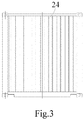
- Fig. 3 is another side view thereof.
- a front end 22 is provided with a corrugated plate 24, and concave and convex portions of the corrugated plate 24 are arranged symmetrically relative to a central line of the front end 22.
- a rear end 23 is provided with a locking device 25, and locking bars 251 of the locking device 25 are provided symmetrically on two doors.
- a corner fitting 26 is positioned at each corner of the container. The position of each corner fitting and the distance therebetween accord with the ISO requirement, such that a sling fitting may be mounted for lifting.
- a 20' container should have an outer container length of 6058mm, i.e., an outer distance between two corner fittings along a longitudinal direction is 6058mm, and an inner container length generally smaller than 6 meters.
- a 40' container should have an outer container length of 12192mm and an inner container length generally smaller than 12.05 meters.
- a 45' container should have an outer container length of 13716mm and an inner container length generally smaller than 13.6 meters.
- the ISO 20' container may not contain five rows of pallets.
- ten rows of pallets may be theoretically arranged in the ISO 40' container, that will, however, cause a waste to the inner container space when the ISO container is used for shipping pallets, that is because, in practice, the ten rows of pallets have to be arranged with enough space intervals left between the pallets (a general inner length has to be greater than 12060mm).
- the present invention provides a freight container, so as to enlarge the inner container size.
- the freight container comprises a container body and corner fittings provided at each corner of the container body, the container body comprising a bottom portion, a top portion, two side portions and two end portions, wherein one end portion is provided with a locking device and the other end portion with a corrugated plate, the locking device and the corrugated plate protrude beyond outer edges of the corner fittings, and the position of each corner fitting and the distance therebetween accord with ISO standards.
- the present invention has the advantageous effect of compared with the prior art: in the present invention, the inner container length is enlarged by extending outwards the rear end and the front end, the outer edges of the locking device and the corrugated plate protruding beyond the corner fittings.
- the pallet container increased number of pallets can be placed, and the cabin space can be fully used.
- the position of the corner fitting and relative distance therebetween are kept unchanged and accord with the ISO standard, hence the alignment of the sling fitting and corner fitting are not influenced, and there will not be interference between the container corner fitting and the T-shaped bar inside the cabin when the container is placed into the cabin.
- the improved container has the enlarged inner space without adapting shape requirements of the existing standard products, such as a standard pallet or T-shaped bar. Further, compared with the containers provided with locking bars having special structure presented in the background section, the present invention can be easily implemented and has smaller manufacturing difficulty.
- the present invention provides a freight container comprising a container body 1 and corner fittings 2 provided at each corner of the container body 1.
- the container body comprises a bottom portion 10, a top portion 20, two side portions 30 and two end portions 40, 50. Wherein one end portion is provided with a locking device 60 and the other end portion with a corrugated plate 70.
- the locking device and the corrugated plate protrude beyond the outer edges of the corner fitting 2, and the position of each corner fitting and the distance therebetween accord with ISO standard.
- This embodiment is described with reference to a 20' freight container. As shown in Fig.
- the distance between two corner fittings along a longitudinal direction of the container is 6058mm, which distance is the same as that of the existing corner fitting and accord with the ISO standard of the 20' container.
- Outer edges of the locking device 60 or of the corrugated plate 70 on the respective end portion protrude beyond outer edges of the corner fittings at a distance of larger than 21mm.
- the inner container length is larger than 6000mm, while the existing ordinary container has an inner container length of smaller than 6000mm.
- the container of the present invention is able to contain more pallets.
- the locking device and the corrugated plate each protrudes beyond the outer edges of the corner fittings at a distance of 50mm.
- the inner container length is enlarged by extending outwards the rear end and the front end,the locking device and the corrugated plate protruding beyond the outer edges of the corner fittings.
- the number of pallets to be placed is increased (taking the 20' container as an example, the number of pallets to be placed is increased by 1 in comparison with the prior 20' container).
- the position of the corner fitting and the distance therebetween is unchanged, hence the alignment of the sling fitting and corner fitting is not influenced.
- the containers in the cabin are typically arranged between T-shaped bars (T-BAR) 3 corresponding to the corner fitting at the ISO standard position in the cabin.
- the position of the corner fitting in the present invention are unchanged, they can be still placed correspondingly between the T-shaped bars 3, and there is no interference between the T-shaped bars 3 and the locking device and/or corrugated plate beyond the bound of the corner fitting.
- Fig. 14 in the present embodiment, when the freight containers are placed in the cabin, two adjacent sides of two containers are imbedded with each other, breaking the distance limit between the corner fitting of the container and the T-shaped bar.
- the outwards extending portion of the container may be filled into the relatively larger gap between the ends of the containers when the containers are arranged, and do not interference with the T-shaped bar.
- the space in the cabin may be used effectively.
- the freight container has two ends, i.e., a front end and a rear end, wherein the front end is provided with the corrugated plate and the rear end is provided with the locking device.
- concave portions 71 and convex portions 72 of the corrugated plate 70 are arranged asymmetrically relative to a central line L1 of the front end.
- the concave portions 71 and convex portion 72 of the corrugated plate 70 are arranged such that, as shown in Fig.
- the corrugated plate 70 when the corrugated plate 70 is rotated at 180 degrees around an intersection point X of the corrugated plate 70 and the longitudinal central line L5 of the container body, the concave portions 71 of the corrugated plate 70 after rotating correspond to the convex portions 72 of the corrugated plate 70 before rotating, and the convex portions 72 of the corrugated plate 70 after rotating correspond to the concave portions 71 of the corrugated plate 70 before rotating.
- the corrugated plate 70 is substantially central-symmetrical relative to a vertical central line L1 of the corrugated plate 70.
- the locking device 60 comprises a plurality of locking bars 61, said locking bars 61 being mounted asymmetrically on two doors of the rear end 40.
- the number of the locking bars 61 is 4, and the locking bars 61 each has a distance D1, D2, D3 and D4 from a central line L2 of the rear end 40, the above distances being different from each other.
- the convex portions of the front end and the rear end of adjacent containers may be staggered when a plurality of containers are arranged, so as to avoid an impact.
- the rear end is adjacent to the front end, and the locking bar of the rear end corresponds to the concave portion of the corrugated plate.
- the concave portion of the corrugated plate of one container is aligned to the convex portion of the corrugated plate of the adjacent container, such that the convex portions of the two adjacent containers can be staggered.
- the distance between adjacent corner fittings is always 76mm.
- the 20' inner container length is maximized by fully using the space staggering.
- the handles 62 on the two doors are at different heights.
- the handle positions can be staggered, avoiding collision between the handles at the same height.
- the freight container further comprises an end lintel which may be a door lintel 81 or a front lintel 82.
- the door lintel 81 is provided on an upper side of the rear end along a transverse direction of the container, and a side of the door lintel 81 is extended outwards the container and beyond the locking bars 61.
- the front lintel 82 is provided on an upper side of the front end along the transverse direction of the container, and a side of the front lintel 82 is extended outwards the container and beyond the corrugated plate 70.
- the front lintel 82 has an edge shape corresponding to that of the corrugated plate 70; and at the side of the locking bars 61, the edge of the door lintel 81 is recessed at a position where it is not corresponding to the locking bars 61, such that the interference between the closely adjacent containers may be avoided when they are lifted up and down.
- the freight container further comprises an end sill which may be a door sill 91 or a front sill 92.
- the door sill 91 is provided on a lower side of the rear end along a transverse direction of the container, and a side of the door sill 91 is extended outwards the container and beyond the locking bars 61.
- the front sill 92 is provided on a lower side of the front end along the transverse direction of the container, and a side of the front sill 92 is extended outwards the container and beyond the corrugated plate 70.
- the front sill 92 has an edge shape corresponding to that of the corrugated plate 70; and at the side of the locking bar 61, the edge of the door sill 91 is recessed at a position where it is not corresponding to the locking bars 61, such that the interference between the closely adjacent containers may be avoided when they are lifted up and down.
- the freight container further comprises an anti-collision portions 100 provided on corner columns of the rear end 40 and front end 50 of the container.
- the anti-collision portions 100 protrude outwards from the rear end and front end.
- the anti-collision portions 100 of the rear end 40 or front end 50 are provided asymmetrically relative to that end, avoiding interference between adjacent containers when arranged.
- the container is provided with a structure protruding outwards the container from the front end and the rear end and beyond the locking bars and the corrugated plate, even if a collision occurs in future, only the protruded structure is impacted, and the damage to the corrugated plate or locking device may be prevented.
- the present embodiment is described with reference to the 20' container.
- the concept of the present invention may be adapted to other types of containers.
- the inner container length of the 40' freight container may be enlarged to more than 12060mm or 12090mm, and the inner container length of the 45' freight container may be enlarged to more than 13600mm.
- the inner container length is enlarged by extending outwards the rear end and the front end, outer edges of the locking device and of the corrugated plate protruding beyond the corner fittings.
- the pallet container increased number of pallets can be placed, and the cabin space can be fully used.
- the positions of the corner fittings and relative distances therebetween are kept unchanged and accord with the ISO standard, hence the alignment of the sling fitting and corner fitting is not influenced, and there will not be interference between the container corner fitting and the T-shaped bar inside the cabin when the container is placed into the cabin.
- the improved container may have the enlarged inner space while adapting shape requirements of the existing standard products, such as a standard pallet or T-shaped bar. Further, compared with the containers provided with locking bar having special structure presented in the background section, the present invention can be easily implemented and has a small manufacturing difficulty.
Landscapes
- Engineering & Computer Science (AREA)
- Mechanical Engineering (AREA)
- Pallets (AREA)
- Packaging Of Machine Parts And Wound Products (AREA)
- Stackable Containers (AREA)
Description
- The present disclosure relates to the field of freight container.
- Generally, a main body of an ordinary freight container includes a container body enclosed by a bottom portion, a top portion, two side portions, a rear end and a front end, as well as a corner fitting at each corner of the container body.
Fig. 1 is a top view of an existing 20' container 200;Fig. 2 is a side view of the container shown inFig. 1 ; andFig. 3 is another side view thereof. As shown inFigs. 1, 2 and3 , afront end 22 is provided with acorrugated plate 24, and concave and convex portions of thecorrugated plate 24 are arranged symmetrically relative to a central line of thefront end 22. A rear end 23 is provided with alocking device 25, andlocking bars 251 of thelocking device 25 are provided symmetrically on two doors. A corner fitting 26 is positioned at each corner of the container. The position of each corner fitting and the distance therebetween accord with the ISO requirement, such that a sling fitting may be mounted for lifting. - According to the ISO requirement, a 20' container should have an outer container length of 6058mm, i.e., an outer distance between two corner fittings along a longitudinal direction is 6058mm, and an inner container length generally smaller than 6 meters. According to the ISO requirement, a 40' container should have an outer container length of 12192mm and an inner container length generally smaller than 12.05 meters. According to the ISO requirement, a 45' container should have an outer container length of 13716mm and an inner container length generally smaller than 13.6 meters. Taking a pallet container as an example, in which a plurality of pallet rows are placed longitudinally, the outer size of a pallet is determined by a standard, and a typical pallet has a size of 1200 x 1200mm or 1200 x 800mm. Thus, if the above-mentioned ordinary freight container is still used for shipping the pallets, the ISO 20' container may not contain five rows of pallets. Further, though ten rows of pallets may be theoretically arranged in the ISO 40' container, that will, however, cause a waste to the inner container space when the ISO container is used for shipping pallets, that is because, in practice, the ten rows of pallets have to be arranged with enough space intervals left between the pallets (a general inner length has to be greater than 12060mm). Similarly, there are difficulties to arranged seventeen rows of pallets when the ISO 45' container is used for shipping 1200 x 800mm pallets. Therefore, when the existing containers in accordance to the ISO requirements is used to contain the pallets, since the sizes of the pallet and inner container are not rationally designed, the pallets cannot be arranged as much as possible, resulting a waste to the inner container space.
- To maximize the inner container size, a special structure of a container door is introduced in a patent document (publication No.
GB2213134A US 6109469A discloses a container including a locking bar disposed within the outer edge of the corner fitting, which cannot maximize the inner length of the container. - Therefore, there is a need to improve the structure of the existing freight container, i.e., to increase the inner container size and decrease the improvement difficulties while keeping the position and relative distance of the corner fittings accord with the ISO standard.
- In view of the above problems, the present invention provides a freight container, so as to enlarge the inner container size.
- To achieve the above purpose, the present invention provides a freight container having the features of
claim 1. The freight container comprises a container body and corner fittings provided at each corner of the container body, the container body comprising a bottom portion, a top portion, two side portions and two end portions, wherein one end portion is provided with a locking device and the other end portion with a corrugated plate, the locking device and the corrugated plate protrude beyond outer edges of the corner fittings, and the position of each corner fitting and the distance therebetween accord with ISO standards. - The present invention has the advantageous effect of compared with the prior art: in the present invention, the inner container length is enlarged by extending outwards the rear end and the front end, the outer edges of the locking device and the corrugated plate protruding beyond the corner fittings. As for the pallet container, increased number of pallets can be placed, and the cabin space can be fully used. In addition, in the present invention the position of the corner fitting and relative distance therebetween are kept unchanged and accord with the ISO standard, hence the alignment of the sling fitting and corner fitting are not influenced, and there will not be interference between the container corner fitting and the T-shaped bar inside the cabin when the container is placed into the cabin. Therefore, in the present invention the improved container has the enlarged inner space without adapting shape requirements of the existing standard products, such as a standard pallet or T-shaped bar. Further, compared with the containers provided with locking bars having special structure presented in the background section, the present invention can be easily implemented and has smaller manufacturing difficulty.
-
-
Fig. 1 is a top view of an existing container. -
Fig. 2 is a side view of the existing container. -
Fig. 3 is another side view of the existing container. -
Fig. 4 is a schematic view showing the existing container arranged in the cabin. -
Fig. 5 is a top view of a container of the present invention. -
Fig. 6 is a side view of the container of the present invention. -
Fig. 7 is another side view of the container of the present invention. -
Fig. 8 is a section view taken along the BB line inFig. 7 . -
Fig. 9 is a section view taken along the CC line inFig. 6 . -
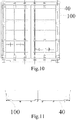
Fig. 10 is a schematic view of an embodiment of a rear end of the freight container of the present invention. -
Fig. 11 is a top view of the embodiment of the rear end of the freight container of the present invention. -
Fig. 12 is a schematic view of an embodiment of a front end of the freight container of the present invention. -
Fig. 13 is a top view of the embodiment of the front end of the freight container of the present invention. -
Fig. 14 is a schematic view showing the container of the present invention arranged in the cabin. -
Fig. 15 is another schematic view showing the container of the present invention arranged in the cabin. -
Fig. 16 is a further schematic view showing the container of the present invention arranged in the cabin. - Examplary embodiments will be described more completely with reference to the accompanying drawings. However, the examplary embodiment can be implemented in various manners, and may not be limited to the embodiments illustrated herein; instead, these embodiments are provided for comprehensive and completeness of the present invention, and to fully communicate the concept of the illustrative embodiments to those skilled in the art. In the drawings, for clarity, the thicknesses of the areas and layers may be exaggerated. Same or similar structures will be indicated by same reference numbers in the drawings, and detailed descriptions thereof will be thus omitted.
- In addition, the described feature, structure or characteristic can be combined with one or more embodiments in any suitable manner within the scope of the appended claims. In the following description, a lot of details are provided for fully understanding the embodiments of the present invention. However, those skilled in the art will appreciate, a technical solution of the present invention may be implemented without one or more of said specific details, or other manners, elements, materials and etc. may be adopted. In other situations, well known structures, materials or operations will not be shown or described, so as to avoid blurring the main technical idea of the present invention.
- As shown in
Fig. 5 , the present invention provides a freight container comprising acontainer body 1 andcorner fittings 2 provided at each corner of thecontainer body 1. The container body comprises abottom portion 10, atop portion 20, twoside portions 30 and twoend portions locking device 60 and the other end portion with acorrugated plate 70. The locking device and the corrugated plate protrude beyond the outer edges of the corner fitting 2, and the position of each corner fitting and the distance therebetween accord with ISO standard. This embodiment is described with reference to a 20' freight container. As shown inFig. 5 , the distance between two corner fittings along a longitudinal direction of the container is 6058mm, which distance is the same as that of the existing corner fitting and accord with the ISO standard of the 20' container. Outer edges of thelocking device 60 or of thecorrugated plate 70 on the respective end portion protrude beyond outer edges of the corner fittings at a distance of larger than 21mm. The inner container length is larger than 6000mm, while the existing ordinary container has an inner container length of smaller than 6000mm. Thus, compared with the existing container, the container of the present invention is able to contain more pallets. Preferably, the locking device and the corrugated plate each protrudes beyond the outer edges of the corner fittings at a distance of 50mm. - Therefore, in the present invention, the inner container length is enlarged by extending outwards the rear end and the front end,the locking device and the corrugated plate protruding beyond the outer edges of the corner fittings. Taking the pallet container as example, the number of pallets to be placed is increased (taking the 20' container as an example, the number of pallets to be placed is increased by 1 in comparison with the prior 20' container). In the present invention the position of the corner fitting and the distance therebetween is unchanged, hence the alignment of the sling fitting and corner fitting is not influenced. Further, in a typical transport ship for containers, the containers in the cabin are typically arranged between T-shaped bars (T-BAR) 3 corresponding to the corner fitting at the ISO standard position in the cabin. Since the position of the corner fitting in the present invention are unchanged, they can be still placed correspondingly between the T-shaped bars 3, and there is no interference between the T-shaped bars 3 and the locking device and/or corrugated plate beyond the bound of the corner fitting. As shown in
Fig. 14 , in the present embodiment, when the freight containers are placed in the cabin, two adjacent sides of two containers are imbedded with each other, breaking the distance limit between the corner fitting of the container and the T-shaped bar. The outwards extending portion of the container may be filled into the relatively larger gap between the ends of the containers when the containers are arranged, and do not interference with the T-shaped bar. Thus the space in the cabin may be used effectively. - The freight container has two ends, i.e., a front end and a rear end, wherein the front end is provided with the corrugated plate and the rear end is provided with the locking device.
- As shown in
Figs. 5 and 6 , in an embodiment,concave portions 71 andconvex portions 72 of thecorrugated plate 70 are arranged asymmetrically relative to a central line L1 of the front end. In an embodiment, theconcave portions 71 andconvex portion 72 of thecorrugated plate 70 are arranged such that, as shown inFig. 5 , when thecorrugated plate 70 is rotated at 180 degrees around an intersection point X of thecorrugated plate 70 and the longitudinal central line L5 of the container body, theconcave portions 71 of thecorrugated plate 70 after rotating correspond to theconvex portions 72 of thecorrugated plate 70 before rotating, and theconvex portions 72 of thecorrugated plate 70 after rotating correspond to theconcave portions 71 of thecorrugated plate 70 before rotating. Thecorrugated plate 70 is substantially central-symmetrical relative to a vertical central line L1 of thecorrugated plate 70. - As shown in
Figs. 5 and7 , the lockingdevice 60 comprises a plurality of lockingbars 61, said locking bars 61 being mounted asymmetrically on two doors of therear end 40. As shown inFig. 7 , the number of the locking bars 61 is 4, and the locking bars 61 each has a distance D1, D2, D3 and D4 from a central line L2 of therear end 40, the above distances being different from each other. - By means of the asymmetrical structure design for the front end and the rear end, the convex portions of the front end and the rear end of adjacent containers may be staggered when a plurality of containers are arranged, so as to avoid an impact.
- As shown in
Fig. 14 , when two 20' containers are joined, the rear end is adjacent to the front end, and the locking bar of the rear end corresponds to the concave portion of the corrugated plate. - As shown in
Fig. 15 , when two 20' containers are joined, the concave portion of the corrugated plate of one container is aligned to the convex portion of the corrugated plate of the adjacent container, such that the convex portions of the two adjacent containers can be staggered. - As shown in
Fig. 16 , when two 20' containers are joined, the locking bars of one container are staggered with the locking bars of the adjacent container. - Therefore, when two 20' containers are joined, whatever a rear end joining the front end, the front end joining the front end, or the rear end joining the rear end, the distance between adjacent corner fittings is always 76mm. There is a staggered arrangement between the locking bars and corrugated plate, the corrugated plate and corrugated plate, or the locking bars and locking bars. The 20' inner container length is maximized by fully using the space staggering.
- In the present embodiment, the
handles 62 on the two doors are at different heights. When the rear ends of two containers are adjacent, the handle positions can be staggered, avoiding collision between the handles at the same height. - As shown in
Figs. 8 and 9 , in the present embodiment, the freight container further comprises an end lintel which may be adoor lintel 81 or afront lintel 82. Thedoor lintel 81 is provided on an upper side of the rear end along a transverse direction of the container, and a side of thedoor lintel 81 is extended outwards the container and beyond the locking bars 61. - The
front lintel 82 is provided on an upper side of the front end along the transverse direction of the container, and a side of thefront lintel 82 is extended outwards the container and beyond thecorrugated plate 70. Preferably, along the transverse direction of the container, at the side of thecorrugated plate 70, thefront lintel 82 has an edge shape corresponding to that of thecorrugated plate 70; and at the side of the locking bars 61, the edge of thedoor lintel 81 is recessed at a position where it is not corresponding to the locking bars 61, such that the interference between the closely adjacent containers may be avoided when they are lifted up and down. - As shown in
Figs. 8 and 9 , in another embodiment, the freight container further comprises an end sill which may be a door sill 91 or afront sill 92. The door sill 91 is provided on a lower side of the rear end along a transverse direction of the container, and a side of the door sill 91 is extended outwards the container and beyond the locking bars 61. Thefront sill 92 is provided on a lower side of the front end along the transverse direction of the container, and a side of thefront sill 92 is extended outwards the container and beyond thecorrugated plate 70. Preferably, along the transverse direction of the container, at the side of thecorrugated plate 70, thefront sill 92 has an edge shape corresponding to that of thecorrugated plate 70; and at the side of the lockingbar 61, the edge of the door sill 91 is recessed at a position where it is not corresponding to the locking bars 61, such that the interference between the closely adjacent containers may be avoided when they are lifted up and down. - As shown in
Figs. 10-13 , in another embodiment, the freight container further comprises ananti-collision portions 100 provided on corner columns of therear end 40 andfront end 50 of the container. Theanti-collision portions 100 protrude outwards from the rear end and front end. Preferably, theanti-collision portions 100 of therear end 40 orfront end 50 are provided asymmetrically relative to that end, avoiding interference between adjacent containers when arranged. - Since the container is provided with a structure protruding outwards the container from the front end and the rear end and beyond the locking bars and the corrugated plate, even if a collision occurs in future, only the protruded structure is impacted, and the damage to the corrugated plate or locking device may be prevented.
- The present embodiment is described with reference to the 20' container. However, the concept of the present invention may be adapted to other types of containers. For example, by extending outwards the rear end and the front end, outer edges of the locking device and of the corrugated plate protruding beyond the corner fittings, the inner container length of the 40' freight container may be enlarged to more than 12060mm or 12090mm, and the inner container length of the 45' freight container may be enlarged to more than 13600mm.
- In view of the above, in the present invention, the inner container length is enlarged by extending outwards the rear end and the front end, outer edges of the locking device and of the corrugated plate protruding beyond the corner fittings. As for the pallet container, increased number of pallets can be placed, and the cabin space can be fully used. In addition, in the present invention the positions of the corner fittings and relative distances therebetween are kept unchanged and accord with the ISO standard, hence the alignment of the sling fitting and corner fitting is not influenced, and there will not be interference between the container corner fitting and the T-shaped bar inside the cabin when the container is placed into the cabin. Therefore, in the present invention the improved container may have the enlarged inner space while adapting shape requirements of the existing standard products, such as a standard pallet or T-shaped bar. Further, compared with the containers provided with locking bar having special structure presented in the background section, the present invention can be easily implemented and has a small manufacturing difficulty.
- Thought the present invention has been described with reference to several typical embodiments, it should be understood that the terms used are illustrative and examplary, rather than limiting terms.
Claims (13)
- A freight container, comprising a container body (1) and corner fittings (2) positioned at each corner of the container body (1), the container body (1) comprising a bottom portion (10), a top portion (20), two side portions (30) and two end portions (40, 50), wherein:at least one end portion is provided with a locking device (60), and the positions of the corner fittings (2) and distance therebetween accord with ISO standard;the two end portions (40, 50) are a front end and a rear end; the front end is provided with a corrugated plate (70) which is protruded beyond outer edges of the corner fittings (2) along a longitudinal direction of the container body (1) characterized in thatthe locking device (60) is protruded beyond outer edges of the corner fittings (2) along the longitudinal direction of the container body (1); andthe locking device (60) comprises locking bars (61) mounted asymmetrically on two doors of the rear end.
- The freight container according to claim 1, wherein concave portions (71) and convex portions (72) of the corrugated plate (70) are arranged asymmetrically relative to a central line of the front end.
- The freight container according to claim 1, wherein the corrugated plate (70) is central-symmetrical relative to a vertical central line (LI) of the corrugated plate (70).
- The freight container according to claim 1, wherein the locking device (60) further comprises handles mounted on the two doors of the rear end, and the handles are at different heights on the two doors.
- The freight container according to claim 1, wherein the freight container further comprises an end lintel provided on an upper side of one of the end portions along a transverse direction of the container, and a side of the end lintel is extended outwards the container and beyond the locking device (60) and/or corrugated plate (70).
- The freight container according to claim 5, wherein at the front end along the transverse direction of the container, the end lintel has an edge shape corresponding to that of the corrugated plate (70), and at the rear end along the transverse direction of the container, the edge of the end lintel is recessed where it is not corresponding to the locking bars (61).
- The freight container according to claim 1, wherein the freight container further comprises an end sill provided on a lower side of one of the end portions along a transverse direction of the container, and a side of the end sill is extended outwards the container and beyond the locking device (60) and/or corrugated plate (70).
- The freight container according to claim 7, wherein at the front end along the transverse direction of the container, the end sill has an edge shape corresponding to that of the corrugated plate (70), and at the rear end along the transverse direction of the container, the edge of the end sill is recessed at a position where it is not corresponding to the locking bars (61).
- The freight container according to claim 1, wherein the freight container further comprises anti-collision portions (100) provided on corner columns of the rear end and front end of the container, and the anti-collision portions (100) protrude outwards from the corner columns of the rear end and front end.
- The freight container according to claim 9, wherein the anti-collision portions (100) are arranged asymmetrically relative to a central line of the rear end or front end.
- The freight container according to claim 1, wherein the corner fittings (2) of the freight container have a position matching with that of the corner fittings of an ISO 20' standard container, and the locking device (60) and/or corrugated plate (70) protrudes beyond the outer edges of the corner fittings (2) at a distance larger than 21 mm, and the inner container length is larger than 6000 mm.
- The freight container according to claim 11, wherein the locking device (60) and corrugated plate (70) each protrudes beyond the outer edges of the corner fittings (2) at a distance of 50mm.
- The freight container according to claim 1, wherein the corner fittings (2) of the freight container have a position matching with that of the corner fittings of an ISO 40' standard container, or that of the corner fittings of an ISO 40' standard container, or that of the corner fittings of an ISO 45' standard container, and the inner container length is larger than 12060 mm, larger than 12090 mm, larger than 13600 mm, respectively.
Applications Claiming Priority (2)
| Application Number | Priority Date | Filing Date | Title |
|---|---|---|---|
| CN201410027274.XA CN104787503B (en) | 2014-01-21 | 2014-01-21 | a shipping container |
| PCT/CN2014/095354 WO2015109919A1 (en) | 2014-01-21 | 2014-12-29 | Freight container |
Publications (3)
| Publication Number | Publication Date |
|---|---|
| EP3098184A1 EP3098184A1 (en) | 2016-11-30 |
| EP3098184A4 EP3098184A4 (en) | 2017-09-06 |
| EP3098184B1 true EP3098184B1 (en) | 2019-11-06 |
Family
ID=53552776
Family Applications (1)
| Application Number | Title | Priority Date | Filing Date |
|---|---|---|---|
| EP14880251.5A Active EP3098184B1 (en) | 2014-01-21 | 2014-12-29 | Freight container |
Country Status (5)
| Country | Link |
|---|---|
| EP (1) | EP3098184B1 (en) |
| CN (1) | CN104787503B (en) |
| DE (1) | DE212014000247U1 (en) |
| PT (1) | PT3098184T (en) |
| WO (1) | WO2015109919A1 (en) |
Family Cites Families (12)
| Publication number | Priority date | Publication date | Assignee | Title |
|---|---|---|---|---|
| SE441820B (en) * | 1984-02-29 | 1985-11-11 | Mattsson Karl Axel | DEVICE FOR DEFENDING THE UNLATED OPENING OF CONTAINERS CLOSING DEVICES |
| GB8516001D0 (en) * | 1985-06-25 | 1985-07-31 | Bell Lines Ltd | Freight containers |
| GB2271375A (en) * | 1992-10-03 | 1994-04-13 | Adamson Modular Systems Limite | Locking arrangement for container doors |
| CN2213134Y (en) | 1994-08-30 | 1995-11-22 | 林宝昌 | Storage box |
| US6109469A (en) * | 1995-10-27 | 2000-08-29 | Clive-Smith; Martin | Freight container |
| CN2640976Y (en) * | 2003-09-05 | 2004-09-15 | 中国国际海运集装箱(集团)股份有限公司 | Container prolonged in internal length |
| CN2823180Y (en) * | 2005-06-02 | 2006-10-04 | 扬州通利冷藏集装箱有限公司 | Step-type door for refrigerating container |
| CN101254849B (en) * | 2007-03-02 | 2010-05-26 | 中国国际海运集装箱(集团)股份有限公司 | container door structure |
| CN201538539U (en) * | 2009-08-10 | 2010-08-04 | 广东新会中集特种运输设备有限公司 | Anti-collision device for platform container and platform container |
| CN203006203U (en) * | 2012-10-12 | 2013-06-19 | 中国人民解放军总后勤部军事交通运输研究所 | Open container |
| CN202987930U (en) * | 2012-12-06 | 2013-06-12 | 南车二七车辆有限公司 | Railway large-volume dry bulk cargo transportation container |
| CN203127543U (en) * | 2012-12-31 | 2013-08-14 | 南通中集特种运输设备制造有限公司 | Container bottom lock and container with same |
-
2014
- 2014-01-21 CN CN201410027274.XA patent/CN104787503B/en active Active
- 2014-12-29 WO PCT/CN2014/095354 patent/WO2015109919A1/en not_active Ceased
- 2014-12-29 PT PT148802515T patent/PT3098184T/en unknown
- 2014-12-29 EP EP14880251.5A patent/EP3098184B1/en active Active
- 2014-12-29 DE DE212014000247.8U patent/DE212014000247U1/en not_active Expired - Lifetime
Non-Patent Citations (1)
| Title |
|---|
| None * |
Also Published As
| Publication number | Publication date |
|---|---|
| PT3098184T (en) | 2020-02-10 |
| EP3098184A1 (en) | 2016-11-30 |
| CN104787503B (en) | 2017-08-11 |
| CN104787503A (en) | 2015-07-22 |
| WO2015109919A1 (en) | 2015-07-30 |
| EP3098184A4 (en) | 2017-09-06 |
| DE212014000247U1 (en) | 2016-09-01 |
Similar Documents
| Publication | Publication Date | Title |
|---|---|---|
| EP3323752B1 (en) | Foldable container | |
| US20160122073A1 (en) | Reinforced containers and blanks for making the same | |
| US12280941B2 (en) | Top side beam of container and container | |
| US9156578B2 (en) | Reinforced polygonal containers and blanks for making the same | |
| BR112016028310B1 (en) | STRUCTURAL ELEMENT | |
| US10894628B2 (en) | Sag-resistant containers and blanks for making the same | |
| EP3978381A1 (en) | Bulk container with interlocking elements | |
| EP2440476B1 (en) | Transport frame | |
| EP2910484B1 (en) | Fastener for dismountably assembling laminar elements | |
| EP2876054B1 (en) | Bulk bin with panel to panel interlock features | |
| US20080187422A1 (en) | Transporting platform and transporting module | |
| EP3098184A1 (en) | Freight container | |
| US9016557B2 (en) | Self-locking support panel for corrugated container | |
| DE102009044314A1 (en) | Stacking aid for keg on pallet, has dome-like regions with filling and emptying opening, where dome like regions lie along longitudinal axis of keg by cylindrical wall | |
| CN205203885U (en) | Tank container and end frame thereof | |
| CN104973353B (en) | tank container | |
| CN204871914U (en) | Fork truck tray | |
| EP2060510B1 (en) | Container | |
| CN209905309U (en) | Packing box convenient for packing and recycling refractory material products | |
| KR101354829B1 (en) | Container for cargo | |
| JP7174075B2 (en) | Liquid transport and storage containers | |
| CN220865995U (en) | A packaging box and display module packaging combination | |
| EP2697445B1 (en) | Reinforcement for casting comprising essentially plane reinforcement elements formed with ring-shaped portions | |
| CN112208961A (en) | Tank container and frame thereof | |
| CN109178656A (en) | A kind of large size logistics transportation container |
Legal Events
| Date | Code | Title | Description |
|---|---|---|---|
| PUAI | Public reference made under article 153(3) epc to a published international application that has entered the european phase |
Free format text: ORIGINAL CODE: 0009012 |
|
| 17P | Request for examination filed |
Effective date: 20160822 |
|
| AK | Designated contracting states |
Kind code of ref document: A1 Designated state(s): AL AT BE BG CH CY CZ DE DK EE ES FI FR GB GR HR HU IE IS IT LI LT LU LV MC MK MT NL NO PL PT RO RS SE SI SK SM TR |
|
| AX | Request for extension of the european patent |
Extension state: BA ME |
|
| DAX | Request for extension of the european patent (deleted) | ||
| A4 | Supplementary search report drawn up and despatched |
Effective date: 20170808 |
|
| RIC1 | Information provided on ipc code assigned before grant |
Ipc: B65D 88/02 20060101ALN20170802BHEP Ipc: B65D 88/12 20060101AFI20170802BHEP Ipc: B65D 90/00 20060101ALI20170802BHEP |
|
| STAA | Information on the status of an ep patent application or granted ep patent |
Free format text: STATUS: EXAMINATION IS IN PROGRESS |
|
| 17Q | First examination report despatched |
Effective date: 20180904 |
|
| REG | Reference to a national code |
Ref country code: DE Ref legal event code: R079 Ref document number: 602014056563 Country of ref document: DE Free format text: PREVIOUS MAIN CLASS: B65D0090020000 Ipc: B65D0088120000 |
|
| RIC1 | Information provided on ipc code assigned before grant |
Ipc: B65D 90/00 20060101ALI20190319BHEP Ipc: B65D 88/12 20060101AFI20190319BHEP Ipc: B65D 88/02 20060101ALN20190319BHEP |
|
| GRAP | Despatch of communication of intention to grant a patent |
Free format text: ORIGINAL CODE: EPIDOSNIGR1 |
|
| STAA | Information on the status of an ep patent application or granted ep patent |
Free format text: STATUS: GRANT OF PATENT IS INTENDED |
|
| INTG | Intention to grant announced |
Effective date: 20190517 |
|
| GRAS | Grant fee paid |
Free format text: ORIGINAL CODE: EPIDOSNIGR3 |
|
| GRAA | (expected) grant |
Free format text: ORIGINAL CODE: 0009210 |
|
| STAA | Information on the status of an ep patent application or granted ep patent |
Free format text: STATUS: THE PATENT HAS BEEN GRANTED |
|
| AK | Designated contracting states |
Kind code of ref document: B1 Designated state(s): AL AT BE BG CH CY CZ DE DK EE ES FI FR GB GR HR HU IE IS IT LI LT LU LV MC MK MT NL NO PL PT RO RS SE SI SK SM TR |
|
| REG | Reference to a national code |
Ref country code: GB Ref legal event code: FG4D |
|
| REG | Reference to a national code |
Ref country code: CH Ref legal event code: EP Ref country code: AT Ref legal event code: REF Ref document number: 1198480 Country of ref document: AT Kind code of ref document: T Effective date: 20191115 |
|
| REG | Reference to a national code |
Ref country code: IE Ref legal event code: FG4D |
|
| REG | Reference to a national code |
Ref country code: DE Ref legal event code: R096 Ref document number: 602014056563 Country of ref document: DE |
|
| REG | Reference to a national code |
Ref country code: PT Ref legal event code: SC4A Ref document number: 3098184 Country of ref document: PT Date of ref document: 20200210 Kind code of ref document: T Free format text: AVAILABILITY OF NATIONAL TRANSLATION Effective date: 20200130 |
|
| REG | Reference to a national code |
Ref country code: NL Ref legal event code: MP Effective date: 20191106 |
|
| REG | Reference to a national code |
Ref country code: LT Ref legal event code: MG4D |
|
| PG25 | Lapsed in a contracting state [announced via postgrant information from national office to epo] |
Ref country code: GR Free format text: LAPSE BECAUSE OF FAILURE TO SUBMIT A TRANSLATION OF THE DESCRIPTION OR TO PAY THE FEE WITHIN THE PRESCRIBED TIME-LIMIT Effective date: 20200207 Ref country code: LT Free format text: LAPSE BECAUSE OF FAILURE TO SUBMIT A TRANSLATION OF THE DESCRIPTION OR TO PAY THE FEE WITHIN THE PRESCRIBED TIME-LIMIT Effective date: 20191106 Ref country code: NL Free format text: LAPSE BECAUSE OF FAILURE TO SUBMIT A TRANSLATION OF THE DESCRIPTION OR TO PAY THE FEE WITHIN THE PRESCRIBED TIME-LIMIT Effective date: 20191106 Ref country code: SE Free format text: LAPSE BECAUSE OF FAILURE TO SUBMIT A TRANSLATION OF THE DESCRIPTION OR TO PAY THE FEE WITHIN THE PRESCRIBED TIME-LIMIT Effective date: 20191106 Ref country code: LV Free format text: LAPSE BECAUSE OF FAILURE TO SUBMIT A TRANSLATION OF THE DESCRIPTION OR TO PAY THE FEE WITHIN THE PRESCRIBED TIME-LIMIT Effective date: 20191106 Ref country code: PL Free format text: LAPSE BECAUSE OF FAILURE TO SUBMIT A TRANSLATION OF THE DESCRIPTION OR TO PAY THE FEE WITHIN THE PRESCRIBED TIME-LIMIT Effective date: 20191106 Ref country code: NO Free format text: LAPSE BECAUSE OF FAILURE TO SUBMIT A TRANSLATION OF THE DESCRIPTION OR TO PAY THE FEE WITHIN THE PRESCRIBED TIME-LIMIT Effective date: 20200206 Ref country code: BG Free format text: LAPSE BECAUSE OF FAILURE TO SUBMIT A TRANSLATION OF THE DESCRIPTION OR TO PAY THE FEE WITHIN THE PRESCRIBED TIME-LIMIT Effective date: 20200206 Ref country code: FI Free format text: LAPSE BECAUSE OF FAILURE TO SUBMIT A TRANSLATION OF THE DESCRIPTION OR TO PAY THE FEE WITHIN THE PRESCRIBED TIME-LIMIT Effective date: 20191106 |
|
| PG25 | Lapsed in a contracting state [announced via postgrant information from national office to epo] |
Ref country code: RS Free format text: LAPSE BECAUSE OF FAILURE TO SUBMIT A TRANSLATION OF THE DESCRIPTION OR TO PAY THE FEE WITHIN THE PRESCRIBED TIME-LIMIT Effective date: 20191106 Ref country code: HR Free format text: LAPSE BECAUSE OF FAILURE TO SUBMIT A TRANSLATION OF THE DESCRIPTION OR TO PAY THE FEE WITHIN THE PRESCRIBED TIME-LIMIT Effective date: 20191106 Ref country code: IS Free format text: LAPSE BECAUSE OF FAILURE TO SUBMIT A TRANSLATION OF THE DESCRIPTION OR TO PAY THE FEE WITHIN THE PRESCRIBED TIME-LIMIT Effective date: 20200306 |
|
| PG25 | Lapsed in a contracting state [announced via postgrant information from national office to epo] |
Ref country code: AL Free format text: LAPSE BECAUSE OF FAILURE TO SUBMIT A TRANSLATION OF THE DESCRIPTION OR TO PAY THE FEE WITHIN THE PRESCRIBED TIME-LIMIT Effective date: 20191106 |
|
| PG25 | Lapsed in a contracting state [announced via postgrant information from national office to epo] |
Ref country code: EE Free format text: LAPSE BECAUSE OF FAILURE TO SUBMIT A TRANSLATION OF THE DESCRIPTION OR TO PAY THE FEE WITHIN THE PRESCRIBED TIME-LIMIT Effective date: 20191106 Ref country code: DK Free format text: LAPSE BECAUSE OF FAILURE TO SUBMIT A TRANSLATION OF THE DESCRIPTION OR TO PAY THE FEE WITHIN THE PRESCRIBED TIME-LIMIT Effective date: 20191106 Ref country code: CZ Free format text: LAPSE BECAUSE OF FAILURE TO SUBMIT A TRANSLATION OF THE DESCRIPTION OR TO PAY THE FEE WITHIN THE PRESCRIBED TIME-LIMIT Effective date: 20191106 Ref country code: ES Free format text: LAPSE BECAUSE OF FAILURE TO SUBMIT A TRANSLATION OF THE DESCRIPTION OR TO PAY THE FEE WITHIN THE PRESCRIBED TIME-LIMIT Effective date: 20191106 Ref country code: RO Free format text: LAPSE BECAUSE OF FAILURE TO SUBMIT A TRANSLATION OF THE DESCRIPTION OR TO PAY THE FEE WITHIN THE PRESCRIBED TIME-LIMIT Effective date: 20191106 |
|
| REG | Reference to a national code |
Ref country code: CH Ref legal event code: PL |
|
| REG | Reference to a national code |
Ref country code: DE Ref legal event code: R097 Ref document number: 602014056563 Country of ref document: DE |
|
| REG | Reference to a national code |
Ref country code: AT Ref legal event code: MK05 Ref document number: 1198480 Country of ref document: AT Kind code of ref document: T Effective date: 20191106 |
|
| REG | Reference to a national code |
Ref country code: BE Ref legal event code: MM Effective date: 20191231 |
|
| PG25 | Lapsed in a contracting state [announced via postgrant information from national office to epo] |
Ref country code: MC Free format text: LAPSE BECAUSE OF FAILURE TO SUBMIT A TRANSLATION OF THE DESCRIPTION OR TO PAY THE FEE WITHIN THE PRESCRIBED TIME-LIMIT Effective date: 20191106 Ref country code: SK Free format text: LAPSE BECAUSE OF FAILURE TO SUBMIT A TRANSLATION OF THE DESCRIPTION OR TO PAY THE FEE WITHIN THE PRESCRIBED TIME-LIMIT Effective date: 20191106 Ref country code: SM Free format text: LAPSE BECAUSE OF FAILURE TO SUBMIT A TRANSLATION OF THE DESCRIPTION OR TO PAY THE FEE WITHIN THE PRESCRIBED TIME-LIMIT Effective date: 20191106 |
|
| PLBE | No opposition filed within time limit |
Free format text: ORIGINAL CODE: 0009261 |
|
| STAA | Information on the status of an ep patent application or granted ep patent |
Free format text: STATUS: NO OPPOSITION FILED WITHIN TIME LIMIT |
|
| 26N | No opposition filed |
Effective date: 20200807 |
|
| PG25 | Lapsed in a contracting state [announced via postgrant information from national office to epo] |
Ref country code: IE Free format text: LAPSE BECAUSE OF NON-PAYMENT OF DUE FEES Effective date: 20191229 Ref country code: LU Free format text: LAPSE BECAUSE OF NON-PAYMENT OF DUE FEES Effective date: 20191229 Ref country code: FR Free format text: LAPSE BECAUSE OF NON-PAYMENT OF DUE FEES Effective date: 20200106 |
|
| PG25 | Lapsed in a contracting state [announced via postgrant information from national office to epo] |
Ref country code: SI Free format text: LAPSE BECAUSE OF FAILURE TO SUBMIT A TRANSLATION OF THE DESCRIPTION OR TO PAY THE FEE WITHIN THE PRESCRIBED TIME-LIMIT Effective date: 20191106 Ref country code: CH Free format text: LAPSE BECAUSE OF NON-PAYMENT OF DUE FEES Effective date: 20191231 Ref country code: BE Free format text: LAPSE BECAUSE OF NON-PAYMENT OF DUE FEES Effective date: 20191231 Ref country code: LI Free format text: LAPSE BECAUSE OF NON-PAYMENT OF DUE FEES Effective date: 20191231 Ref country code: AT Free format text: LAPSE BECAUSE OF FAILURE TO SUBMIT A TRANSLATION OF THE DESCRIPTION OR TO PAY THE FEE WITHIN THE PRESCRIBED TIME-LIMIT Effective date: 20191106 |
|
| PG25 | Lapsed in a contracting state [announced via postgrant information from national office to epo] |
Ref country code: IT Free format text: LAPSE BECAUSE OF FAILURE TO SUBMIT A TRANSLATION OF THE DESCRIPTION OR TO PAY THE FEE WITHIN THE PRESCRIBED TIME-LIMIT Effective date: 20191106 |
|
| PG25 | Lapsed in a contracting state [announced via postgrant information from national office to epo] |
Ref country code: CY Free format text: LAPSE BECAUSE OF FAILURE TO SUBMIT A TRANSLATION OF THE DESCRIPTION OR TO PAY THE FEE WITHIN THE PRESCRIBED TIME-LIMIT Effective date: 20191106 |
|
| PG25 | Lapsed in a contracting state [announced via postgrant information from national office to epo] |
Ref country code: HU Free format text: LAPSE BECAUSE OF FAILURE TO SUBMIT A TRANSLATION OF THE DESCRIPTION OR TO PAY THE FEE WITHIN THE PRESCRIBED TIME-LIMIT; INVALID AB INITIO Effective date: 20141229 Ref country code: MT Free format text: LAPSE BECAUSE OF FAILURE TO SUBMIT A TRANSLATION OF THE DESCRIPTION OR TO PAY THE FEE WITHIN THE PRESCRIBED TIME-LIMIT Effective date: 20191106 |
|
| PGFP | Annual fee paid to national office [announced via postgrant information from national office to epo] |
Ref country code: PT Payment date: 20211216 Year of fee payment: 8 Ref country code: GB Payment date: 20211222 Year of fee payment: 8 |
|
| PG25 | Lapsed in a contracting state [announced via postgrant information from national office to epo] |
Ref country code: TR Free format text: LAPSE BECAUSE OF FAILURE TO SUBMIT A TRANSLATION OF THE DESCRIPTION OR TO PAY THE FEE WITHIN THE PRESCRIBED TIME-LIMIT Effective date: 20191106 |
|
| PG25 | Lapsed in a contracting state [announced via postgrant information from national office to epo] |
Ref country code: MK Free format text: LAPSE BECAUSE OF FAILURE TO SUBMIT A TRANSLATION OF THE DESCRIPTION OR TO PAY THE FEE WITHIN THE PRESCRIBED TIME-LIMIT Effective date: 20191106 |
|
| PG25 | Lapsed in a contracting state [announced via postgrant information from national office to epo] |
Ref country code: PT Free format text: LAPSE BECAUSE OF NON-PAYMENT OF DUE FEES Effective date: 20230629 |
|
| GBPC | Gb: european patent ceased through non-payment of renewal fee |
Effective date: 20221229 |
|
| PG25 | Lapsed in a contracting state [announced via postgrant information from national office to epo] |
Ref country code: GB Free format text: LAPSE BECAUSE OF NON-PAYMENT OF DUE FEES Effective date: 20221229 |
|
| PGFP | Annual fee paid to national office [announced via postgrant information from national office to epo] |
Ref country code: DE Payment date: 20251222 Year of fee payment: 12 |