EP3098120A2 - Seat belt retractor and seat belt device - Google Patents
Seat belt retractor and seat belt device Download PDFInfo
- Publication number
- EP3098120A2 EP3098120A2 EP16171784.8A EP16171784A EP3098120A2 EP 3098120 A2 EP3098120 A2 EP 3098120A2 EP 16171784 A EP16171784 A EP 16171784A EP 3098120 A2 EP3098120 A2 EP 3098120A2
- Authority
- EP
- European Patent Office
- Prior art keywords
- pawl
- spool
- locking base
- restraint portion
- seatbelt retractor
- Prior art date
- Legal status (The legal status is an assumption and is not a legal conclusion. Google has not performed a legal analysis and makes no representation as to the accuracy of the status listed.)
- Granted
Links
- 230000002159 abnormal effect Effects 0.000 abstract description 7
- 230000002093 peripheral effect Effects 0.000 description 11
- 230000004048 modification Effects 0.000 description 8
- 238000012986 modification Methods 0.000 description 8
- 230000001133 acceleration Effects 0.000 description 4
- 210000000078 claw Anatomy 0.000 description 2
- 238000003780 insertion Methods 0.000 description 2
- 230000037431 insertion Effects 0.000 description 2
- 230000000717 retained effect Effects 0.000 description 2
- 238000013459 approach Methods 0.000 description 1
- 230000001419 dependent effect Effects 0.000 description 1
- 230000000452 restraining effect Effects 0.000 description 1
- 230000000087 stabilizing effect Effects 0.000 description 1
- 238000004804 winding Methods 0.000 description 1
Images


Classifications
-
- B—PERFORMING OPERATIONS; TRANSPORTING
- B60—VEHICLES IN GENERAL
- B60R—VEHICLES, VEHICLE FITTINGS, OR VEHICLE PARTS, NOT OTHERWISE PROVIDED FOR
- B60R22/00—Safety belts or body harnesses in vehicles
- B60R22/34—Belt retractors, e.g. reels
-
- B—PERFORMING OPERATIONS; TRANSPORTING
- B60—VEHICLES IN GENERAL
- B60R—VEHICLES, VEHICLE FITTINGS, OR VEHICLE PARTS, NOT OTHERWISE PROVIDED FOR
- B60R22/00—Safety belts or body harnesses in vehicles
- B60R22/34—Belt retractors, e.g. reels
- B60R22/36—Belt retractors, e.g. reels self-locking in an emergency
- B60R22/38—Belt retractors, e.g. reels self-locking in an emergency responsive only to belt movement
-
- B—PERFORMING OPERATIONS; TRANSPORTING
- B60—VEHICLES IN GENERAL
- B60R—VEHICLES, VEHICLE FITTINGS, OR VEHICLE PARTS, NOT OTHERWISE PROVIDED FOR
- B60R22/00—Safety belts or body harnesses in vehicles
- B60R22/34—Belt retractors, e.g. reels
- B60R22/36—Belt retractors, e.g. reels self-locking in an emergency
- B60R22/405—Belt retractors, e.g. reels self-locking in an emergency responsive to belt movement and vehicle movement
Definitions
- the present invention relates to a seatbelt retractor and a seatbelt device, and more particularly, to a seatbelt retractor having a lock mechanism engageable with a base plate and a seatbelt device including the seatbelt retractor.
- Vehicles such as automobiles, are generally provided with a seatbelt device that restrains an occupant on a seat including a seat section on which the occupant sits and a backrest section located on the back of the occupant.
- a seatbelt device includes webbing that restrains the occupant, a seatbelt retractor that retracts the webbing, a guide anchor provided on a vehicle body to guide the webbing, a belt anchor that fixes the webbing to the vehicle body, a buckle disposed on a side surface of the seat, and a tongue disposed on the webbing. The occupant is restrained in the seat by the webbing by fitting the tongue in the buckle.
- Such a seatbelt retractor often includes a spool that retracts the webbing, a base frame that houses the spool rotatably, a spring unit that applies retracting force to the spool, a vehicle sensor that detects rapid deceleration of the vehicle, a lock mechanism actuated by the vehicle sensor to engage the spool with the base frame, and a pretensioner that removes the slack of the webbing in an emergency such as a vehicle collision (see, for example, Japanese Unexamined Patent Application Publication No. 2014-80121 and Japanese Unexamined Patent Application Publication No. 2000-289571 ).
- the above-described lock mechanism often includes a base lock (also referred to as a locking base) connected to an end portion of the spool, a lock plate (also referred to as a pawl) disposed movably outward in the radial direction relative to the base lock, and ratchet teeth (also referred to as engaging teeth) provided on an inner rim of an aperture provided in the base frame.
- a base lock also referred to as a locking base
- a lock plate also referred to as a pawl
- ratchet teeth also referred to as engaging teeth
- the above-described lock plate (pawl) is disposed in a recess (receiving portion) provided in the lock base (locking base), and is retreated at a position such as not to engage with the ratchet teeth (engaging teeth) of the base frame in a normal state (an unlocked state). Since the lock plate (pawl) is structured to move outward in the radial direction relative to the base lock and to engage with the ratchet teeth (engaging teeth) of the base frame in an emergency such as a vehicle collision, it is loosely fitted in the receiving portion. Therefore, for example, when vibrations occur in the seatbelt retractor, the lock plate (pawl) hits a wall surface of the receiving portion, and this causes abnormal noise.
- the present invention has been made in view of such a problem, and an object of the present invention is to provide a seatbelt retractor and a seatbelt device that can suppress the occurrence of abnormal noise.
- the present invention provides a seatbelt retractor including a spool that retracts webbing configured to restrain an occupant, a base frame that houses the spool rotatably, and a lock mechanism that restricts rotation of the spool.
- the lock mechanism includes a locking base disposed in an end portion of the spool, a pawl disposed to protrude outward from an outer periphery of the locking base, a pawl spring that biases the pawl inward relative to the locking base, and a lock gear coaxially disposed to rotate relative to the locking base.
- the pawl includes a first restraint portion that restrains movement of the pawl in one rotating direction of the spool while being located inside the outer periphery of the locking base, and a second restraint portion that restrains the movement of the pawl in an opposite rotating direction of the spool while the movement of the pawl is retrained by the first restraint portion.
- the present invention also provides a seatbelt device including webbing that restrains an occupant, a seatbelt retractor that retracts the webbing, a guide anchor provided on a vehicle body to guide the webbing, a belt anchor that fixes the webbing to the vehicle body, a buckle disposed on a side surface of a seat on which the occupant sits, and a tongue disposed on the webbing.
- the seatbelt retractor includes a spool that retracts the webbing, a base frame that houses the spool rotatably, and a lock mechanism that restricts rotation of the spool.
- the lock mechanism includes a locking base disposed in an end portion of the spool, a pawl disposed to protrude outward from an outer periphery of the locking base, a pawl spring that biases the pawl inward relative to the locking base, and a lock gear disposed coaxially with the locking base to rotate relative to the locking base.
- the pawl includes a first restraint portion that restrains movement of the pawl in one rotating direction of the spool while being located inside the outer periphery of the locking base, and a second restraint portion that restrains the movement of the pawl in an opposite rotating direction of the spool while the movement is retrained by the first restraint portion.
- the pawl may be received in a recess provided in the spool or the locking base.
- the first restraint portion may be a portion in contact with a component having the recess
- the second restraint portion may be a portion in contact with the component having the recess or the lock gear.
- the first restraint portion may be a portion in contact with a component having the recess
- the second restraint portion may be a portion in contact with the lock gear
- the first restraint portion and the second restraint portion may form a wedge shape with respect to the component having the recess and the lock gear.
- the lock gear may include an engaging portion engageable with the component having the recess in a state in which the movement of the pawl is restrained by the first restraint portion.
- the first restraint portion and the second restraint portion may be portions in contact with the component having the recess, and the first restraint portion and the second restraint portion may form a wedge shape with respect to the component having the recess.
- the pawl that constitutes the lock mechanism when the pawl that constitutes the lock mechanism is received (in a non-operation state), the movement of the pawl can be restrained in both rotating directions of the spool by the first restraint portion and the second restraint portion, the movement relative to the locking base can be suppressed, and the occurrence of abnormal noise can be suppressed.
- Fig. 1 is a component developed view of a seatbelt retractor according to an embodiment of the present invention.
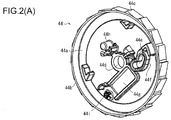
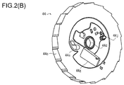
- Figs. 2(A) and 2(B) are explanatory views of a lock gear illustrated in Fig. 1
- Fig. 2(A) is a perspective view from the front side
- Fig. 2(B) is a perspective view from the back side.
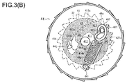
- Figs. 3(A) and 3(B) are explanatory views illustrating the operation of the seatbelt retractor illustrated in Fig. 1
- Fig. 3(A) illustrates a normal state
- Fig. 3(B) illustrates a lock mechanism operating state.
- illustration of webbing is omitted for convenience of explanation.
- a seatbelt retractor 1 includes a spool 2 that retracts webbing for restraining the occupant, a base frame 3 that houses the spool 2 rotatably, and a lock mechanism 4 that restricts the rotation of the spool 2.
- the lock mechanism 4 includes a locking base 41 disposed in an end portion of the spool 2, a pawl 42 disposed on the locking base 41 and disposed to protrude outward from an outer periphery of the locking base 41, a pawl spring 43 that biases the pawl 42 inward relative to the locking base 41, and a lock gear 44 disposed coaxially with the locking base 41 to rotate relative to the locking base 41.
- the pawl 42 includes a first restraint portion 42a that restrains the movement of the pawl 42 in one rotating direction of the spool 2 while being located on an inner side of the outer periphery of the locking base 41, and a second restraint portion 42b that restrains the movement of the pawl 42 in an opposite rotating direction of the spool 2 while the movement is restrained by the first restraint portion 42a.
- the spool 2 is a winding drum for retracting the webbing.
- the spool 2 is rotatably supported at one end by a spring unit 5, and is connected at the other end to the locking base 41.
- the locking base 41 is rotatably supported by a retainer cover 6 with a cap 61 being disposed therebetween.
- the spring unit 5 is a component that biases the spool 2 in a retracting direction, and contains a spiral spring.
- the retainer cover 6 is a component that receives the lock mechanism 4 and a vehicle sensor 7. The spring unit 5 and the retainer cover 6 are directly or indirectly fixed to the base frame 3.
- the seatbelt retractor 1 may further include a pretensioner 8 that removes the slack of the webbing in an emergency such as a vehicle collision.
- the pretensioner 8 is disposed inside the base frame 3 adjacent to the locking base 41, and only a pipe 81 that discharges a mass body for rotating the spool 2 is illustrated in Fig. 1 .
- the arrangement of the pretensioner 8 is not limited to the illustrated one.
- the pretensioner 8 may be disposed outside the base frame 3 adjacent to the locking base 41 or may be disposed inside the spring unit 5.
- the base frame 3 is a frame structure having a substantially angular U-shaped cross section.
- a pair of wall members that form side surfaces are provided at opposite ends of a wall member that forms a rear surface.
- the pair of wall members that form the side surfaces have apertures 31 through which end portions of the spool 2 (including the locking base 41) are passed.
- a tie plate that forms a front surface may be connected to distal ends of the pair of wall members that form the side surfaces.
- engaging teeth 32 are provided on inner rims of the apertures 31.
- the side surface of the base frame 3 may have an aperture 33 that retains the vehicle sensor 7.
- the vehicle sensor 7 includes a spherical mass body 71, a sensor lever 72 to be swung by movement of the mass body 71, and a sensor cover 73 that receives and retains the mass body 71 and the sensor lever 72 in the aperture 33.
- the mass body 71 disturbs its balance and pushes the sensor lever 72 upward, and a distal end of the sensor lever 72 engages with the lock gear 44, so that the rotation of the lock gear 44 is restricted.
- the lock mechanism 4 includes the locking base 41, the pawl 42, the pawl spring 43, the lock gear 44, a protect cover 45 that restricts movement of the pawl 42 in the axial direction of the spool 2, a flywheel 46 swingably disposed on the lock gear 44, and a hook spring 47 that biases a distal end of the flywheel 46 inward in the radial direction.
- the locking base 41 is inserted in the aperture 31 of the base frame 3 and is disposed so that an outer peripheral portion thereof is opposed to the engaging teeth 32.
- the locking base 41 has enough thickness to form a receiving portion for the pawl 42, and has, in a front surface, a recess 411 for receiving the pawl 42.
- the locking base 41 includes a shaft portion 412 that forms a rotation shaft of the spool 2, and a plurality of projections 413 that fixes the protect cover 45.
- the recess 411 includes a wide portion 411a provided along the outer periphery of the locking base 41 to extend wide to a portion near the shaft portion 412, and a guide portion 411b extending from the wide portion 411a toward the opposite outer periphery around the shaft portion 412.
- the wide portion 411 a includes a first wall surface portion 411c provided on a side far from the guide portion 411b and a second wall surface portion 411d provided on a side close to the guide portion 411b.
- Figs. 3(A) and 3(B) for convenience of explanation, components of the lock gear 44 are shown by solid lines, and the engaging teeth 32 of the base frame 3, the locking base 41, the pawl 42, and the pawl spring 43 are shown by one-dot chain lines. Surfaces of the locking base 41 and the pawl 42 are painted in gray.
- the first wall surface portion 411c is provided opposed to one rotating direction of the spool 2 (clockwise direction in the figures).
- the second wall surface portion 411d is provided opposed to an opposite rotating direction of the spool 2 (counterclockwise direction in the figures).
- the distance between the first wall surface portion 411c and the second wall surface portion 411 d may decrease from the outer periphery of the locking base 41 toward the center.
- first wall surface portion 411c may be shaped to be convex in the opposite rotating direction of the spool 2 (counterclockwise direction in the figures).
- second wall surface portion 411d may be shaped to be concave in the opposite rotating direction of the spool 2 (counterclockwise direction in the figures).
- the second wall surface portion 411d may be provided to continue from a wall surface portion for forming the guide portion 411b with almost the same curvature.
- the pawl 42 includes a head portion 421 received in the wide portion 411a that constitutes the recess 411 of the locking base 41 and a tail portion 422 received in the guide portion 411b that constitutes the recess 411 of the locking base 41.
- the pawl 42 has substantially the same outer shape as that of the recess 411, and is loosely fitted in the recess 411.
- teeth portion 421a are provided along the outer periphery of the locking base 41.
- the head portion 421 has a first restraint portion 42a provided along the first wall surface portion 411c of the wide portion 411a to be in contact therewith.
- the first restraint portion 42a has a concave shape corresponding to the convex shape of the first wall surface portion 411 c. This shape allows the first restraint portion 42a to be movable toward the outer side of the outer periphery of the locking base 41 while being in contact with the first wall surface portion 411c.
- the tail portion 422 is disposed in the guide portion 411b to have the function of stabilizing the posture of the pawl 42 when the head portion 421 moves to the outer side or the inner side of the outer periphery of the locking base 41.
- the pawl 42 has a pawl pin 423 that is passed through an aperture (cam hole 44e) provided in the lock gear 44 and moves the pawl 42 when relative rotation occurs between the locking base 41 and the lock gear 44.
- the pawl 42 may be configured movable toward the outer side of the outer periphery of the locking base 41 by sliding, or may be configured movable toward the outer side of the outer periphery by turning.
- the shape of the recess 411 of the locking base 41 for receiving the pawl 42 is not limited to the illustrated shape, and can be appropriately changed according to the shape and structure of the pawl 42.
- the present invention is not limited to such an embodiment.
- the surface of the end portion of the spool 2 may have the recess 411 for receiving the pawl 42. Therefore, in the embodiment "component having the recess 411" refers to the locking base 41 or the spool 2.
- the lock gear 44 includes a disc portion 44a disposed opposed to the locking base 41 and an outer peripheral wall 44b standing outward along an outer rim of the disc portion 44a.
- engaging teeth 44c are provided to be engageable with the sensor lever 72 of the vehicle sensor 7.
- the disc portion 44a has, for example, an insertion hole 44d through which the shaft portion 412 of the locking base 41 is passed, a substantially V-shaped cam hole 44e through which the pawl pin 423 is passed, a guide wall 44f standing outward along an outer periphery of the cam hole 44e to guide the pawl pin 423, an aperture 44g that avoids interference with the pawl spring 43, a support pin 44h that supports the flywheel 46 swingably, and a hook pin 44i that supports one end of the pawl spring 43.
- the cam hole 44e and the guide wall 44f constitute a cam mechanism that guides movement of the pawl 42, and have the function of guiding the pawl 42 to push the pawl 42 to the outer side of the outer periphery of the locking base 41.
- the cam hole 44e and the guide wall 44f have, for example, a first guide portion 441 provided in the substantially circumferential direction and a second guide portion 442 provided in the substantially radial direction.
- the first guide portion 441 and the second guide portion 442 form a substantially V-shape to be convex toward the outer periphery.
- the shape of the guide portion for guiding the pawl 42 is not limited to the substantially V-shape, and may be, for example, a substantially U-shape, a substantially J-shape, or a substantially C-shape.
- the pawl spring 43 is retained at one end by the hook pin 44i, is retained at the other end by the pawl pin 423, and is disposed so that a coil part thereof can expand and contract within the aperture 44g.
- the pawl 42 is biased by the pawl spring 43 so that the first restraint portion 42a is pressed against the first wall surface portion 411c, as illustrated.
- a projection-like engaging portion 44j is provided on a back surface of the disc portion 44a to be engageable with the locking base 41.
- the front surface of the locking base 41 has a slot 414 in which the engaging portion 44j can be inserted.
- the slot 414 is provided along the rotating direction of the locking base 41, has a first end surface 414a in the counterclockwise direction in the figures, and has a second end surface 414b in the clockwise direction in the figures.
- the engaging portion 44j and the first end surface 414a are provided to touch with each other before the pawl pin 423 touches a surface of the second guide portion 442 close to the first wall surface portion 411c in a state in which the first restraint portion 42a of the pawl 42 is pressed against the first wall surface portion 411c. That is, when the pawl 42 is pulled inward by the pawl spring 43, the first restraint portion 42a of the pawl 42 touches the first wall surface portion 411c of the locking base 41, and the pawl 42 and the locking base 41 move in the clockwise direction in the figures.
- the lock gear 44 has the engaging portion 44j that can engage with the locking base 41 in a state in which the movement of the pawl 42 is restrained by the first restraint portion 42a.
- an extension of the portion where the first restraint portion 42a of the pawl 42 is in contact with the first wall surface portion 411c of the locking base 41 is taken as Lp1
- an extension of the portion where the second restraint portion 42b of the pawl 42 is in contact with the second guide portion 442 of the lock gear 44 is taken as Lp2.
- the extension Lp1 and the extension Lp2 are provided to intersect near the shaft portion 412 of the locking base 41. That is, the first restraint portion 42a is a portion in contact with the locking base 41, and the second restraint portion 42b is a portion in contact with the lock gear 44.
- the first restraint portion 42a and the second restraint portion 42b form a wedge shape with respect to the locking base 41 and the lock gear 44.
- first restraint portion 42a and the second restraint portion 42b that form the wedge shape in the pawl 42 when the pawl 42 is received (non-operation state of the lock mechanism 4), it can be clamped from both sides by the locking base 41 and the lock gear 44, and this can restrict the movement of the pawl 42 in both rotating directions of the spool 2 and can suppress the movement of the pawl 42 relative to the locking base 41. Therefore, even when vibrations occur in the seatbelt retractor 1, the movement of the pawl 42 can be restricted, and the occurrence of abnormal noise can be suppressed.
- the protect cover 45 has a cutout 45a through which the pawl pin 423 of the pawl 42 is passed and an aperture 45b through which the engaging portion 44j of the lock gear 44 is passed.
- the retainer cover 6 has a substantially cylindrical projecting portion 62 that covers the outer periphery of the outer peripheral wall 44b of the lock gear 44. Inside the projecting portion 62, an inner peripheral wall (not illustrated) is provided on the inner side of the outer peripheral wall 44b of the lock gear 44. Therefore, when the lock mechanism 4 is assembled, the outer peripheral wall 44b of the lock gear 44 is inserted between the inner peripheral wall and the projecting portion 62, and the flywheel 46 is disposed on the inner side of the inner peripheral wall. An inner surface of the inner peripheral wall is provided with a claw (not illustrated) to be engageable with the distal end of the flywheel 46.
- the lock mechanism 4 having the above-described structure, in the normal state (when the withdraw acceleration of the webbing is less than or equal to a predetermined threshold value), the locking base 41 and the lock gear 44 rotate together along with the rotation of the spool 2. Therefore, since the spool 2 (locking base 41) and the lock gear 44 do not rotate relative to each other in the normal state, the pawl 42 is kept in the state retreated at the position such as not to interfere with the engaging teeth 32 of the base frame 3, as illustrated in Fig. 3(A) . At this time, since the movement of the pawl 42 is restrained by the locking base 41 and the lock gear 44, abnormal noise is not caused.
- the flywheel 46 swings and engages with the claw of the retainer cover 6 (not illustrated), and this restricts the rotation of the lock gear 44.
- the distal end of the sensor lever 72 engages with the engaging teeth 44c provided on the outer surface of the outer peripheral wall 44b of the lock gear 44, and this also restricts the rotation of the lock gear 44.
- the engaging portion 44j of the lock gear 44 moves along the slot 414 provided in the locking base 41. Therefore, the length of the slot 414 (distance in the rotating direction from the first end surface 414a to the second end surface 414b) is designed to be more than the amount of relative rotation caused between the locking base 41 and the lock gear 44 until the pawl 42 engages with the base frame 3.
- a projection may be provided on the front surface of the locking base 41 and a slot-like engaging portion may be provided in the back surface of the lock gear 44.
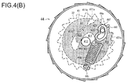
- FIGS. 4(A) and 4(B) are explanatory views of the modification of the seatbelt retractor
- Fig. 4(A) illustrates a normal state
- Fig. 4(B) illustrates a lock mechanism operating state.
- the same components as those of the above-described embodiment are denoted by the same reference numerals, and redundant descriptions thereof are omitted.
- a lock gear 44 components of a lock gear 44 are shown by solid lines, engaging teeth 32 of a base frame 3, a locking base 41, a pawl 42, and a pawl spring 43 are shown by one-dot chain lines, and surfaces of the locking base 41 and the pawl 42 are filled in gray.
- a second restraint portion 42b is changed. Specifically, in this modification, an inclined surface 411e inclined toward a shaft portion 412 is provided in a distal end portion of a second wall surface portion 411d that forms a recess 411 of the locking base 41, and a projecting portion (second restraint portion 42b) to be in contact with the inclined surface 411e is provided in a head portion 421 of the pawl 42. As illustrated, the second restraint portion 42b is provided on a side opposite from a first restraint portion 42a, for example, near the boundary between the head portion 421 and a tail portion 422.
- the first restraint portion 42a of the pawl 42 touches a first wall surface portion 411c of the locking base 41.
- the pawl pin 423 touches a guide wall 44f, and the lock gear 44 is thereby positioned.
- the second restraint portion 42b touches the inclined surface 411e, and the pawl 42 is thereby positioned.
- an extension of a portion of the first restraint portion 42a of the pawl 42 that touches the first wall surface portion 411c of the locking base 41 is taken as Lp1
- an extension of a portion of the second restraint portion 42b of the pawl 42 that touches the inclined surface 411e of the locking base 41 is taken as Lp2.
- the extension Lp1 and the extension Lp2 are provided to intersect near the shaft portion 412 of the locking base 41. That is, the first restraint portion 42a and the second restraint portion 42b are portions in contact with the locking base 41, and the first restraint portion 42a and the second restraint portion 42b form a wedge shape with respect to the locking base 41.
- the pawl 42 in the received state of the pawl 42 (non-operation state of the lock mechanism 4), the pawl 42 can be clamped from both sides by the first wall surface portion 411c and the inclined surface 411e of the locking base 41, the movement of the pawl 42 in both of the rotating directions of the spool 2 can be restrained by the first restraint portion 42a and the second restraint portion 42b, and the movement of the pawl 42 relative to the locking base 41 can be suppressed. Therefore, even when vibrations occur in the seatbelt retractor 1, the movement of the pawl 42 can be restricted, and this can suppress the occurrence of abnormal noise.
- Fig. 5 is an overall configuration view of the seatbelt device according to the embodiment of the present invention.
- components other than the seatbelt device are shown by one-dot chain lines.
- a seatbelt device 100 of the embodiment illustrated in Fig. 5 includes webbing W that restrains an occupant, a seatbelt retractor 1 that retracts the webbing W, a guide anchor 101 provided on the vehicle body to guide the webbing W, a belt anchor 102 that fixes the webbing W to the vehicle body, a buckle 103 disposed on a side surface of a seat S on which the occupant sits, and a tongue 104 disposed on the webbing W.
- the seatbelt retractor 1 has the structures illustrated in Figs. 1 to 4(B) .
- the seat S includes a seat section S1 on which the occupant sits, a backrest section S2 located on the back of the occupant, and a headrest section S3 that supports the head of the occupant.
- the seatbelt retractor 1 is built in a B-pillar P of the vehicle body.
- the buckle 103 is often disposed on a side surface of the seat section S1, and the belt anchor 102 is often disposed on a lower surface of the seat section S1.
- the guide anchor 101 is often disposed on the B-pillar P.
- the webbing W is connected at one end to the belt anchor 102, and is connected at the other end to the seatbelt retractor 1 with the guide anchor 101 being disposed therebetween.
- the webbing W is withdrawn from the seatbelt retractor 1 while sliding in an insertion hole of the guide anchor 101.
- the webbing W is retracted by the action of a spring unit 5 of the seatbelt retractor 1 until a fixed load is applied thereto.
- seatbelt device 100 is obtained by applying the seatbelt retractor 1 of the above embodiment to a normal seatbelt device at the front seat, for example, it may be applied to the rear seat without using the guide anchor 101.
- the present invention is not limited to the above-described embodiment, and various modifications can be made without departing from the spirit of the present invention, for example, the present invention may, of course, be applied to a seatbelt device used in conveyances other than the vehicle.
Abstract
Description
- The present invention relates to a seatbelt retractor and a seatbelt device, and more particularly, to a seatbelt retractor having a lock mechanism engageable with a base plate and a seatbelt device including the seatbelt retractor.
- Vehicles, such as automobiles, are generally provided with a seatbelt device that restrains an occupant on a seat including a seat section on which the occupant sits and a backrest section located on the back of the occupant. Such a seatbelt device includes webbing that restrains the occupant, a seatbelt retractor that retracts the webbing, a guide anchor provided on a vehicle body to guide the webbing, a belt anchor that fixes the webbing to the vehicle body, a buckle disposed on a side surface of the seat, and a tongue disposed on the webbing. The occupant is restrained in the seat by the webbing by fitting the tongue in the buckle.
- Such a seatbelt retractor often includes a spool that retracts the webbing, a base frame that houses the spool rotatably, a spring unit that applies retracting force to the spool, a vehicle sensor that detects rapid deceleration of the vehicle, a lock mechanism actuated by the vehicle sensor to engage the spool with the base frame, and a pretensioner that removes the slack of the webbing in an emergency such as a vehicle collision (see, for example, Japanese Unexamined Patent Application Publication No.
2014-80121 2000-289571 - For example, as described in Japanese Unexamined Patent Application Publication No.
2000-289571 - As described in Japanese Unexamined Patent Application Publication No.
2000-289571 - The present invention has been made in view of such a problem, and an object of the present invention is to provide a seatbelt retractor and a seatbelt device that can suppress the occurrence of abnormal noise.
- This need is met by the features of
independent claim 1. The dependent claims define embodiments. - The present invention provides a seatbelt retractor including a spool that retracts webbing configured to restrain an occupant, a base frame that houses the spool rotatably, and a lock mechanism that restricts rotation of the spool. The lock mechanism includes a locking base disposed in an end portion of the spool, a pawl disposed to protrude outward from an outer periphery of the locking base, a pawl spring that biases the pawl inward relative to the locking base, and a lock gear coaxially disposed to rotate relative to the locking base. The pawl includes a first restraint portion that restrains movement of the pawl in one rotating direction of the spool while being located inside the outer periphery of the locking base, and a second restraint portion that restrains the movement of the pawl in an opposite rotating direction of the spool while the movement of the pawl is retrained by the first restraint portion.
- The present invention also provides a seatbelt device including webbing that restrains an occupant, a seatbelt retractor that retracts the webbing, a guide anchor provided on a vehicle body to guide the webbing, a belt anchor that fixes the webbing to the vehicle body, a buckle disposed on a side surface of a seat on which the occupant sits, and a tongue disposed on the webbing. The seatbelt retractor includes a spool that retracts the webbing, a base frame that houses the spool rotatably, and a lock mechanism that restricts rotation of the spool. The lock mechanism includes a locking base disposed in an end portion of the spool, a pawl disposed to protrude outward from an outer periphery of the locking base, a pawl spring that biases the pawl inward relative to the locking base, and a lock gear disposed coaxially with the locking base to rotate relative to the locking base. The pawl includes a first restraint portion that restrains movement of the pawl in one rotating direction of the spool while being located inside the outer periphery of the locking base, and a second restraint portion that restrains the movement of the pawl in an opposite rotating direction of the spool while the movement is retrained by the first restraint portion.
- In the seatbelt retractor and the seatbelt device of the present invention described above, the pawl may be received in a recess provided in the spool or the locking base.
- The first restraint portion may be a portion in contact with a component having the recess, and the second restraint portion may be a portion in contact with the component having the recess or the lock gear.
- The first restraint portion may be a portion in contact with a component having the recess, the second restraint portion may be a portion in contact with the lock gear, and the first restraint portion and the second restraint portion may form a wedge shape with respect to the component having the recess and the lock gear. The lock gear may include an engaging portion engageable with the component having the recess in a state in which the movement of the pawl is restrained by the first restraint portion.
- The first restraint portion and the second restraint portion may be portions in contact with the component having the recess, and the first restraint portion and the second restraint portion may form a wedge shape with respect to the component having the recess.
- According to the seatbelt retractor and the seatbelt device of the present invention described above, when the pawl that constitutes the lock mechanism is received (in a non-operation state), the movement of the pawl can be restrained in both rotating directions of the spool by the first restraint portion and the second restraint portion, the movement relative to the locking base can be suppressed, and the occurrence of abnormal noise can be suppressed.
-
-
Fig. 1 is a component developed view of a seatbelt retractor according to an embodiment of the present invention. -
Figs. 2(A) and2(B) are explanatory views of a lock gear illustrated inFig. 1 ,Fig. 2(A) is a perspective view from the front side, andFig. 2(B) is a perspective view from the back side. -
Figs. 3(A) and3(B) are explanatory views illustrating the operation of the seatbelt retractor illustrated inFig. 1 ,Fig. 3(A) illustrates a normal state, andFig. 3(B) illustrates a lock mechanism operating state. -
Figs. 4(A) and4(B) are explanatory views of a modification of a seatbelt retractor,Fig. 4(A) illustrates a normal state, andFig. 4(B) illustrates a lock mechanism operating state. -
Fig. 5 is an overall configuration view of a seatbelt device according to an embodiment of the present invention. - An embodiment of the present invention will be described below with reference to
Figs. 1 to 5 . Here,Fig. 1 is a component developed view of a seatbelt retractor according to an embodiment of the present invention.Figs. 2(A) and2(B) are explanatory views of a lock gear illustrated inFig. 1 ,Fig. 2(A) is a perspective view from the front side, andFig. 2(B) is a perspective view from the back side.Figs. 3(A) and3(B) are explanatory views illustrating the operation of the seatbelt retractor illustrated inFig. 1 ,Fig. 3(A) illustrates a normal state, andFig. 3(B) illustrates a lock mechanism operating state. InFig. 1 , illustration of webbing is omitted for convenience of explanation. - As illustrated in
Fig. 1 , aseatbelt retractor 1 according to the embodiment of the present invention includes aspool 2 that retracts webbing for restraining the occupant, abase frame 3 that houses thespool 2 rotatably, and alock mechanism 4 that restricts the rotation of thespool 2. Thelock mechanism 4 includes alocking base 41 disposed in an end portion of thespool 2, apawl 42 disposed on thelocking base 41 and disposed to protrude outward from an outer periphery of thelocking base 41, apawl spring 43 that biases thepawl 42 inward relative to thelocking base 41, and alock gear 44 disposed coaxially with thelocking base 41 to rotate relative to thelocking base 41. Thepawl 42 includes afirst restraint portion 42a that restrains the movement of thepawl 42 in one rotating direction of thespool 2 while being located on an inner side of the outer periphery of thelocking base 41, and asecond restraint portion 42b that restrains the movement of thepawl 42 in an opposite rotating direction of thespool 2 while the movement is restrained by thefirst restraint portion 42a. - The
spool 2 is a winding drum for retracting the webbing. For example, thespool 2 is rotatably supported at one end by aspring unit 5, and is connected at the other end to thelocking base 41. Thelocking base 41 is rotatably supported by a retainer cover 6 with acap 61 being disposed therebetween. Thespring unit 5 is a component that biases thespool 2 in a retracting direction, and contains a spiral spring. The retainer cover 6 is a component that receives thelock mechanism 4 and avehicle sensor 7. Thespring unit 5 and the retainer cover 6 are directly or indirectly fixed to thebase frame 3. - The seatbelt
retractor 1 may further include apretensioner 8 that removes the slack of the webbing in an emergency such as a vehicle collision. In the embodiment, thepretensioner 8 is disposed inside thebase frame 3 adjacent to thelocking base 41, and only apipe 81 that discharges a mass body for rotating thespool 2 is illustrated inFig. 1 . The arrangement of thepretensioner 8 is not limited to the illustrated one. Thepretensioner 8 may be disposed outside thebase frame 3 adjacent to thelocking base 41 or may be disposed inside thespring unit 5. - For example, the
base frame 3 is a frame structure having a substantially angular U-shaped cross section. A pair of wall members that form side surfaces are provided at opposite ends of a wall member that forms a rear surface. The pair of wall members that form the side surfaces haveapertures 31 through which end portions of the spool 2 (including the locking base 41) are passed. A tie plate that forms a front surface may be connected to distal ends of the pair of wall members that form the side surfaces. As illustrated inFig. 1 ,engaging teeth 32 are provided on inner rims of theapertures 31. - The side surface of the
base frame 3 may have anaperture 33 that retains thevehicle sensor 7. For example, thevehicle sensor 7 includes aspherical mass body 71, asensor lever 72 to be swung by movement of themass body 71, and asensor cover 73 that receives and retains themass body 71 and thesensor lever 72 in theaperture 33. According to thisvehicle sensor 7, when a deceleration or a tilt more than or equal to a predetermined value occurs in the vehicle body, themass body 71 disturbs its balance and pushes thesensor lever 72 upward, and a distal end of thesensor lever 72 engages with thelock gear 44, so that the rotation of thelock gear 44 is restricted. - For example, the
lock mechanism 4 includes thelocking base 41, thepawl 42, thepawl spring 43, thelock gear 44, aprotect cover 45 that restricts movement of thepawl 42 in the axial direction of thespool 2, aflywheel 46 swingably disposed on thelock gear 44, and a hook spring 47 that biases a distal end of theflywheel 46 inward in the radial direction. - As illustrated in
Fig. 1 , thelocking base 41 is inserted in theaperture 31 of thebase frame 3 and is disposed so that an outer peripheral portion thereof is opposed to theengaging teeth 32. Thelocking base 41 has enough thickness to form a receiving portion for thepawl 42, and has, in a front surface, arecess 411 for receiving thepawl 42. Thelocking base 41 includes ashaft portion 412 that forms a rotation shaft of thespool 2, and a plurality ofprojections 413 that fixes theprotect cover 45. - For example, as illustrated in
Fig. 3(A) , therecess 411 includes awide portion 411a provided along the outer periphery of the lockingbase 41 to extend wide to a portion near theshaft portion 412, and aguide portion 411b extending from thewide portion 411a toward the opposite outer periphery around theshaft portion 412. Thewide portion 411 a includes a firstwall surface portion 411c provided on a side far from theguide portion 411b and a secondwall surface portion 411d provided on a side close to theguide portion 411b. - In
Figs. 3(A) and3(B) , for convenience of explanation, components of thelock gear 44 are shown by solid lines, and the engagingteeth 32 of thebase frame 3, the lockingbase 41, thepawl 42, and thepawl spring 43 are shown by one-dot chain lines. Surfaces of the lockingbase 41 and thepawl 42 are painted in gray. - The first
wall surface portion 411c is provided opposed to one rotating direction of the spool 2 (clockwise direction in the figures). The secondwall surface portion 411d is provided opposed to an opposite rotating direction of the spool 2 (counterclockwise direction in the figures). The distance between the firstwall surface portion 411c and the secondwall surface portion 411 d may decrease from the outer periphery of the lockingbase 41 toward the center. - For example, the first
wall surface portion 411c may be shaped to be convex in the opposite rotating direction of the spool 2 (counterclockwise direction in the figures). For example, the secondwall surface portion 411d may be shaped to be concave in the opposite rotating direction of the spool 2 (counterclockwise direction in the figures). The secondwall surface portion 411d may be provided to continue from a wall surface portion for forming theguide portion 411b with almost the same curvature. - For example, as illustrated in
Fig. 3(A) , thepawl 42 includes ahead portion 421 received in thewide portion 411a that constitutes therecess 411 of the lockingbase 41 and atail portion 422 received in theguide portion 411b that constitutes therecess 411 of the lockingbase 41. As illustrated, thepawl 42 has substantially the same outer shape as that of therecess 411, and is loosely fitted in therecess 411. On the outer periphery of thehead portion 421,teeth portion 421a are provided along the outer periphery of the lockingbase 41. - The
head portion 421 has afirst restraint portion 42a provided along the firstwall surface portion 411c of thewide portion 411a to be in contact therewith. As illustrated, thefirst restraint portion 42a has a concave shape corresponding to the convex shape of the firstwall surface portion 411 c. This shape allows thefirst restraint portion 42a to be movable toward the outer side of the outer periphery of the lockingbase 41 while being in contact with the firstwall surface portion 411c. - The
tail portion 422 is disposed in theguide portion 411b to have the function of stabilizing the posture of thepawl 42 when thehead portion 421 moves to the outer side or the inner side of the outer periphery of the lockingbase 41. - As illustrated in
Figs. 1 and3(A) , thepawl 42 has apawl pin 423 that is passed through an aperture (cam hole 44e) provided in thelock gear 44 and moves thepawl 42 when relative rotation occurs between the lockingbase 41 and thelock gear 44. - The
pawl 42 may be configured movable toward the outer side of the outer periphery of the lockingbase 41 by sliding, or may be configured movable toward the outer side of the outer periphery by turning. The shape of therecess 411 of the lockingbase 41 for receiving thepawl 42 is not limited to the illustrated shape, and can be appropriately changed according to the shape and structure of thepawl 42. - While the locking
base 41 is connected to the end portion of thespool 2 and the surface of the end portion has therecess 411 for receiving thepawl 42 in the embodiment, as described above, the present invention is not limited to such an embodiment. For example, when anannular locking base 41 is connected the outer periphery of the end portion of thespool 2 or when thespool 2 and the lockingbase 41 are integrally formed, the surface of the end portion of thespool 2 may have therecess 411 for receiving thepawl 42. Therefore, in the embodiment "component having therecess 411" refers to the lockingbase 41 or thespool 2. - For example, as illustrated in
Figs. 1 ,2(A) , and2(B) , thelock gear 44 includes adisc portion 44a disposed opposed to the lockingbase 41 and an outerperipheral wall 44b standing outward along an outer rim of thedisc portion 44a. On an outer surface of the outerperipheral wall 44b, engagingteeth 44c are provided to be engageable with thesensor lever 72 of thevehicle sensor 7. - As illustrated in
Fig. 2(A) , thedisc portion 44a has, for example, aninsertion hole 44d through which theshaft portion 412 of the lockingbase 41 is passed, a substantially V-shapedcam hole 44e through which thepawl pin 423 is passed, aguide wall 44f standing outward along an outer periphery of thecam hole 44e to guide thepawl pin 423, anaperture 44g that avoids interference with thepawl spring 43, asupport pin 44h that supports theflywheel 46 swingably, and ahook pin 44i that supports one end of thepawl spring 43. - The
cam hole 44e and theguide wall 44f constitute a cam mechanism that guides movement of thepawl 42, and have the function of guiding thepawl 42 to push thepawl 42 to the outer side of the outer periphery of the lockingbase 41. Further, to change the moving track of thepawl 42, thecam hole 44e and theguide wall 44f have, for example, afirst guide portion 441 provided in the substantially circumferential direction and asecond guide portion 442 provided in the substantially radial direction. For example, thefirst guide portion 441 and thesecond guide portion 442 form a substantially V-shape to be convex toward the outer periphery. The shape of the guide portion for guiding thepawl 42 is not limited to the substantially V-shape, and may be, for example, a substantially U-shape, a substantially J-shape, or a substantially C-shape. - As illustrated in
Fig. 3(A) , thepawl spring 43 is retained at one end by thehook pin 44i, is retained at the other end by thepawl pin 423, and is disposed so that a coil part thereof can expand and contract within theaperture 44g. In a normal state (a non-operation state of the lock mechanism 4), thepawl 42 is biased by thepawl spring 43 so that thefirst restraint portion 42a is pressed against the firstwall surface portion 411c, as illustrated. - As illustrated in
Fig. 2(B) , a projection-like engagingportion 44j is provided on a back surface of thedisc portion 44a to be engageable with the lockingbase 41. As illustrated inFigs. 1 and3(A) , the front surface of the lockingbase 41 has aslot 414 in which the engagingportion 44j can be inserted. Theslot 414 is provided along the rotating direction of the lockingbase 41, has afirst end surface 414a in the counterclockwise direction in the figures, and has asecond end surface 414b in the clockwise direction in the figures. - As illustrated in
Fig. 3(A) , the engagingportion 44j and thefirst end surface 414a are provided to touch with each other before thepawl pin 423 touches a surface of thesecond guide portion 442 close to the firstwall surface portion 411c in a state in which thefirst restraint portion 42a of thepawl 42 is pressed against the firstwall surface portion 411c. That is, when thepawl 42 is pulled inward by thepawl spring 43, thefirst restraint portion 42a of thepawl 42 touches the firstwall surface portion 411c of the lockingbase 41, and thepawl 42 and the lockingbase 41 move in the clockwise direction in the figures. After that, the engagingportion 44j and thefirst end surface 414a touch with each other, and this restricts relative rotation between the lockingbase 41 and thelock gear 44. Therefore, thelock gear 44 has the engagingportion 44j that can engage with the lockingbase 41 in a state in which the movement of thepawl 42 is restrained by thefirst restraint portion 42a. - When the
pawl 42 is further pulled inward by thepawl spring 43, thepawl pin 423 moves in contact with the surface of thesecond guide portion 442 far from the firstwall surface portion 411 c. This portion of thepawl pin 423 in contact with thesecond guide portion 442 forms thesecond restraint portion 42b of thepawl 42. - Here, an extension of the portion where the
first restraint portion 42a of thepawl 42 is in contact with the firstwall surface portion 411c of the lockingbase 41 is taken as Lp1, and an extension of the portion where thesecond restraint portion 42b of thepawl 42 is in contact with thesecond guide portion 442 of thelock gear 44 is taken as Lp2. As illustrated inFig. 3(A) , the extension Lp1 and the extension Lp2 are provided to intersect near theshaft portion 412 of the lockingbase 41. That is, thefirst restraint portion 42a is a portion in contact with the lockingbase 41, and thesecond restraint portion 42b is a portion in contact with thelock gear 44. Thefirst restraint portion 42a and thesecond restraint portion 42b form a wedge shape with respect to the lockingbase 41 and thelock gear 44. - By thus forming the
first restraint portion 42a and thesecond restraint portion 42b that form the wedge shape in thepawl 42, when thepawl 42 is received (non-operation state of the lock mechanism 4), it can be clamped from both sides by the lockingbase 41 and thelock gear 44, and this can restrict the movement of thepawl 42 in both rotating directions of thespool 2 and can suppress the movement of thepawl 42 relative to the lockingbase 41. Therefore, even when vibrations occur in theseatbelt retractor 1, the movement of thepawl 42 can be restricted, and the occurrence of abnormal noise can be suppressed. - Besides apertures through which the
shaft portion 412 and theprojections 413 of the lockingbase 41 are passed, theprotect cover 45 has acutout 45a through which thepawl pin 423 of thepawl 42 is passed and anaperture 45b through which the engagingportion 44j of thelock gear 44 is passed. - The retainer cover 6 has a substantially cylindrical projecting
portion 62 that covers the outer periphery of the outerperipheral wall 44b of thelock gear 44. Inside the projectingportion 62, an inner peripheral wall (not illustrated) is provided on the inner side of the outerperipheral wall 44b of thelock gear 44. Therefore, when thelock mechanism 4 is assembled, the outerperipheral wall 44b of thelock gear 44 is inserted between the inner peripheral wall and the projectingportion 62, and theflywheel 46 is disposed on the inner side of the inner peripheral wall. An inner surface of the inner peripheral wall is provided with a claw (not illustrated) to be engageable with the distal end of theflywheel 46. - According to the
lock mechanism 4 having the above-described structure, in the normal state (when the withdraw acceleration of the webbing is less than or equal to a predetermined threshold value), the lockingbase 41 and thelock gear 44 rotate together along with the rotation of thespool 2. Therefore, since the spool 2 (locking base 41) and thelock gear 44 do not rotate relative to each other in the normal state, thepawl 42 is kept in the state retreated at the position such as not to interfere with the engagingteeth 32 of thebase frame 3, as illustrated inFig. 3(A) . At this time, since the movement of thepawl 42 is restrained by the lockingbase 41 and thelock gear 44, abnormal noise is not caused. - When the withdraw acceleration of the webbing is higher than the regular withdraw acceleration, that is, when the withdraw acceleration of the webbing exceeds the predetermined threshold value, the
flywheel 46 swings and engages with the claw of the retainer cover 6 (not illustrated), and this restricts the rotation of thelock gear 44. When thevehicle sensor 7 is actuated, the distal end of thesensor lever 72 engages with the engagingteeth 44c provided on the outer surface of the outerperipheral wall 44b of thelock gear 44, and this also restricts the rotation of thelock gear 44. - When the rotation of the
lock gear 44 is thus restricted, relative rotation occurs between the spool 2 (locking base 41) and thelock gear 44. Along with the relative rotation, thepawl 42 slides along therecess 411, and theteeth portion 421a of thepawl 42 approaches and engages with the engagingteeth 32 provided on the inner rim of theaperture 31 of thebase frame 3, as illustrated inFig. 3(B) . As a result, the rotation of the locking base 41 (spool 2) is restricted, and withdraw of the webbing is restricted. - In the operating state of the
lock mechanism 4 illustrated inFig. 3(B) , the engagingportion 44j of thelock gear 44 moves along theslot 414 provided in the lockingbase 41. Therefore, the length of the slot 414 (distance in the rotating direction from thefirst end surface 414a to thesecond end surface 414b) is designed to be more than the amount of relative rotation caused between the lockingbase 41 and thelock gear 44 until thepawl 42 engages with thebase frame 3. - While the projection-like engaging
portion 44j is provided on the back surface of thelock gear 44 and theslot 414 is provided in the front surface of the lockingbase 41 in the above-described embodiment, a projection may be provided on the front surface of the lockingbase 41 and a slot-like engaging portion may be provided in the back surface of thelock gear 44. - Next, a modification of the above-described
seatbelt retractor 1 will be described with reference toFigs. 4(A) and4(B) . Here,Figs. 4(A) and4(B) are explanatory views of the modification of the seatbelt retractor,Fig. 4(A) illustrates a normal state, andFig. 4(B) illustrates a lock mechanism operating state. The same components as those of the above-described embodiment are denoted by the same reference numerals, and redundant descriptions thereof are omitted. - In
Figs. 4(A) and4(B) , for convenience of explanation, components of alock gear 44 are shown by solid lines, engagingteeth 32 of abase frame 3, a lockingbase 41, apawl 42, and apawl spring 43 are shown by one-dot chain lines, and surfaces of the lockingbase 41 and thepawl 42 are filled in gray. - In the modification illustrated in
Figs. 4(A) and4(B) , the position of asecond restraint portion 42b is changed. Specifically, in this modification, aninclined surface 411e inclined toward ashaft portion 412 is provided in a distal end portion of a secondwall surface portion 411d that forms arecess 411 of the lockingbase 41, and a projecting portion (second restraint portion 42b) to be in contact with theinclined surface 411e is provided in ahead portion 421 of thepawl 42. As illustrated, thesecond restraint portion 42b is provided on a side opposite from afirst restraint portion 42a, for example, near the boundary between thehead portion 421 and atail portion 422. - In the modification, when the
pawl 42 is pulled inward by thepawl spring 43, thefirst restraint portion 42a of thepawl 42 touches a firstwall surface portion 411c of the lockingbase 41. After that, thepawl pin 423 touches aguide wall 44f, and thelock gear 44 is thereby positioned. When thepawl 42 is further pulled inward by thepawl spring 43, thesecond restraint portion 42b touches theinclined surface 411e, and thepawl 42 is thereby positioned. - Here, an extension of a portion of the
first restraint portion 42a of thepawl 42 that touches the firstwall surface portion 411c of the lockingbase 41 is taken as Lp1, and an extension of a portion of thesecond restraint portion 42b of thepawl 42 that touches theinclined surface 411e of the lockingbase 41 is taken as Lp2. As illustrated inFig. 4(A) , the extension Lp1 and the extension Lp2 are provided to intersect near theshaft portion 412 of the lockingbase 41. That is, thefirst restraint portion 42a and thesecond restraint portion 42b are portions in contact with the lockingbase 41, and thefirst restraint portion 42a and thesecond restraint portion 42b form a wedge shape with respect to the lockingbase 41. - According to this modification, in the received state of the pawl 42 (non-operation state of the lock mechanism 4), the
pawl 42 can be clamped from both sides by the firstwall surface portion 411c and theinclined surface 411e of the lockingbase 41, the movement of thepawl 42 in both of the rotating directions of thespool 2 can be restrained by thefirst restraint portion 42a and thesecond restraint portion 42b, and the movement of thepawl 42 relative to the lockingbase 41 can be suppressed. Therefore, even when vibrations occur in theseatbelt retractor 1, the movement of thepawl 42 can be restricted, and this can suppress the occurrence of abnormal noise. - Next, a seatbelt device according to an embodiment of the present invention will be described with reference to
Fig. 5 . Here,Fig. 5 is an overall configuration view of the seatbelt device according to the embodiment of the present invention. InFig. 5 , for convenience of explanation, components other than the seatbelt device are shown by one-dot chain lines. - A
seatbelt device 100 of the embodiment illustrated inFig. 5 includes webbing W that restrains an occupant, aseatbelt retractor 1 that retracts the webbing W, aguide anchor 101 provided on the vehicle body to guide the webbing W, abelt anchor 102 that fixes the webbing W to the vehicle body, abuckle 103 disposed on a side surface of a seat S on which the occupant sits, and atongue 104 disposed on the webbing W. For example, theseatbelt retractor 1 has the structures illustrated inFigs. 1 to 4(B) . - Components other than the
seatbelt retractor 1 will be briefly described below. For example, the seat S includes a seat section S1 on which the occupant sits, a backrest section S2 located on the back of the occupant, and a headrest section S3 that supports the head of the occupant. For example, theseatbelt retractor 1 is built in a B-pillar P of the vehicle body. - In general, the
buckle 103 is often disposed on a side surface of the seat section S1, and thebelt anchor 102 is often disposed on a lower surface of the seat section S1. Theguide anchor 101 is often disposed on the B-pillar P. The webbing W is connected at one end to thebelt anchor 102, and is connected at the other end to theseatbelt retractor 1 with theguide anchor 101 being disposed therebetween. - Therefore, when the
tongue 104 is fitted in thebuckle 103, the webbing W is withdrawn from theseatbelt retractor 1 while sliding in an insertion hole of theguide anchor 101. When the occupant wears the seatbelt or releases the seatbelt to get off the vehicle, the webbing W is retracted by the action of aspring unit 5 of theseatbelt retractor 1 until a fixed load is applied thereto. - While the above-described
seatbelt device 100 is obtained by applying theseatbelt retractor 1 of the above embodiment to a normal seatbelt device at the front seat, for example, it may be applied to the rear seat without using theguide anchor 101. - The present invention is not limited to the above-described embodiment, and various modifications can be made without departing from the spirit of the present invention, for example, the present invention may, of course, be applied to a seatbelt device used in conveyances other than the vehicle.
Claims (7)
- A seatbelt retractor (1) comprising: a spool (2) that retracts webbing configured to restrain an occupant; a base frame (3) that houses the spool (2) rotatably; and a lock mechanism (4) that restricts rotation of the spool (2),wherein the lock mechanism (4) includes a locking base (41) disposed in an end portion of the spool (2), a pawl (42) disposed to protrude outward from an outer periphery of the locking base (41), a pawl spring (43) that biases the pawl (42) inward relative to the locking base (41), and a lock gear (44) disposed coaxially with the locking base (41) to rotate relative to the locking base (41), andwherein the pawl (42) includes a first restraint portion (42a) that restrains movement of the pawl (42) in one rotating direction of the spool (2) while being located inside the outer periphery of the locking base (41), and a second restraint portion (42b) that restrains the movement of the pawl (42) in an opposite rotating direction of the spool (2) while the movement of the pawl (42) is retrained by the first restraint portion (42a).
- The seatbelt retractor (1) according to Claim 1, wherein the pawl (42) is received in a recess provided in the spool (2) or the locking base (41).
- The seatbelt retractor (1) according to Claim 2, wherein the first restraint portion (42a) is a portion in contact with a component having the recess, and the second restraint portion (42b) is a portion in contact with the component having the recess or the lock gear (44).
- The seatbelt retractor (1) according to Claim 2, wherein the first restraint portion (42a) is a portion in contact with a component having the recess, the second restraint portion (42b) is a portion in contact with the lock gear (44), and the first restraint portion (42a) and the second restraint portion (42b) form a wedge shape with respect to the component having the recess and the lock gear (44).
- The seatbelt retractor (1) according to Claim 4, wherein the lock gear (44) includes an engaging portion engageable with the component having the recess in the state in which the movement of the pawl (42) is restrained by the first restraint portion (42a).
- The seatbelt retractor (1) according to Claim 2, wherein the first restraint portion (42a) and the second restraint portion (42b) are portions in contact with a component having the recess, and the first restraint portion (42a) and the second restraint portion (42b) form a wedge shape with respect to the component having the recess.
- A seatbelt device comprising: webbing that restrains an occupant, a seatbelt retractor (1) that retracts the webbing, a guide anchor provided on a vehicle body to guide the webbing, a belt anchor that fixes the webbing to the vehicle body, a buckle disposed on a side surface of a seat on which the occupant sits, and a tongue disposed on the webbing,wherein the seatbelt retractor (1) is the seatbelt retractor (1) according to any one of Claims 1 to 6.
Applications Claiming Priority (1)
| Application Number | Priority Date | Filing Date | Title |
|---|---|---|---|
| JP2015108259A JP6566725B2 (en) | 2015-05-28 | 2015-05-28 | Seat belt retractor and seat belt device |
Publications (4)
| Publication Number | Publication Date |
|---|---|
| EP3098120A2 true EP3098120A2 (en) | 2016-11-30 |
| EP3098120A3 EP3098120A3 (en) | 2017-01-04 |
| EP3098120B1 EP3098120B1 (en) | 2018-05-09 |
| EP3098120B8 EP3098120B8 (en) | 2018-06-27 |
Family
ID=56081420
Family Applications (1)
| Application Number | Title | Priority Date | Filing Date |
|---|---|---|---|
| EP16171784.8A Not-in-force EP3098120B8 (en) | 2015-05-28 | 2016-05-27 | Seat belt retractor and seat belt device |
Country Status (3)
| Country | Link |
|---|---|
| US (1) | US9884607B2 (en) |
| EP (1) | EP3098120B8 (en) |
| JP (1) | JP6566725B2 (en) |
Cited By (2)
| Publication number | Priority date | Publication date | Assignee | Title |
|---|---|---|---|---|
| DE102019126029A1 (en) * | 2019-09-26 | 2021-04-01 | Joyson Safety Systems Germany Gmbh | Arrangement with ratchet wheel and lever and belt retractor with ratchet wheel and lever |
| WO2021216020A1 (en) * | 2020-04-21 | 2021-10-28 | Ark Pres Emniyet Kemeri San.Ve Tic.A.S. | Improvement in the locking system of a seat belt |
Families Citing this family (9)
| Publication number | Priority date | Publication date | Assignee | Title |
|---|---|---|---|---|
| JP6539102B2 (en) * | 2015-04-28 | 2019-07-03 | Joyson Safety Systems Japan株式会社 | Seat belt retractor and seat belt device |
| KR101841160B1 (en) * | 2016-05-25 | 2018-03-22 | 주식회사 우신세이프티시스템 | Intelligent Retractor Having Noise Removal Unit |
| KR101803755B1 (en) * | 2016-05-25 | 2017-12-04 | 주식회사 우신세이프티시스템 | Intelligent Retractor Having Mode Changing Lever |
| CN109131206A (en) * | 2018-07-20 | 2019-01-04 | 芜湖金安世腾汽车安全系统有限公司 | A kind of automobile rear seat safety belt retractor |
| CN109177915A (en) | 2018-09-14 | 2019-01-11 | 延锋汽车智能安全系统有限责任公司 | Seat belt retractor and safety belt assembly |
| CN109177916A (en) | 2018-09-14 | 2019-01-11 | 延锋汽车智能安全系统有限责任公司 | Seat belt retractor and safety belt assembly |
| CN109398299B (en) * | 2018-11-05 | 2024-04-16 | 沈阳金杯锦恒汽车安全系统有限公司 | Retractor and method of operating the same |
| JP7156214B2 (en) * | 2019-08-30 | 2022-10-19 | トヨタ自動車株式会社 | vehicle seat belt device |
| CN112622810B (en) * | 2020-12-22 | 2022-04-22 | 宁波均胜汽车安全系统有限公司 | Noise reduction coiler |
Citations (2)
| Publication number | Priority date | Publication date | Assignee | Title |
|---|---|---|---|---|
| JP2000289571A (en) | 1999-04-09 | 2000-10-17 | Tokai Rika Co Ltd | Webbing winding device |
| JP2014080121A (en) | 2012-10-17 | 2014-05-08 | Autoliv Development Ab | Seat belt retractor |
Family Cites Families (13)
| Publication number | Priority date | Publication date | Assignee | Title |
|---|---|---|---|---|
| JPS5857191B2 (en) | 1978-12-29 | 1983-12-19 | エヌエスケ−・ワ−ナ−株式会社 | Seat belt retractor with emergency lock mechanism |
| GB2330802A (en) * | 1997-10-28 | 1999-05-05 | Alliedsignal Ltd | Webbing sensor |
| JP5078110B2 (en) * | 2006-06-15 | 2012-11-21 | タカタ株式会社 | Seat belt retractor and seat belt device provided with the same |
| JP2011246013A (en) * | 2010-05-27 | 2011-12-08 | Tokai Rika Co Ltd | Webbing take-up device and method for manufacturing rotation detecting member |
| JP5797381B2 (en) | 2010-05-27 | 2015-10-21 | 株式会社東海理化電機製作所 | Webbing take-up device |
| JP5511076B2 (en) * | 2010-09-21 | 2014-06-04 | タカタ株式会社 | Seat belt retractor and seat belt device provided with the same |
| JP5676283B2 (en) * | 2011-01-11 | 2015-02-25 | 株式会社東海理化電機製作所 | Webbing take-up device |
| JP2013035444A (en) * | 2011-08-09 | 2013-02-21 | Takata Corp | Retractor device for seatbelt and seatbelt device |
| JP6045933B2 (en) * | 2013-02-12 | 2016-12-14 | 芦森工業株式会社 | Seat belt retractor |
| JP6113562B2 (en) * | 2013-04-12 | 2017-04-12 | 株式会社東海理化電機製作所 | Webbing take-up device |
| JP6539102B2 (en) * | 2015-04-28 | 2019-07-03 | Joyson Safety Systems Japan株式会社 | Seat belt retractor and seat belt device |
| JP6306537B2 (en) * | 2015-05-29 | 2018-04-04 | 株式会社東海理化電機製作所 | Webbing take-up device |
| JP6576794B2 (en) * | 2015-11-05 | 2019-09-18 | 株式会社東海理化電機製作所 | Webbing take-up device |
-
2015
- 2015-05-28 JP JP2015108259A patent/JP6566725B2/en active Active
-
2016
- 2016-05-26 US US15/165,527 patent/US9884607B2/en not_active Expired - Fee Related
- 2016-05-27 EP EP16171784.8A patent/EP3098120B8/en not_active Not-in-force
Patent Citations (2)
| Publication number | Priority date | Publication date | Assignee | Title |
|---|---|---|---|---|
| JP2000289571A (en) | 1999-04-09 | 2000-10-17 | Tokai Rika Co Ltd | Webbing winding device |
| JP2014080121A (en) | 2012-10-17 | 2014-05-08 | Autoliv Development Ab | Seat belt retractor |
Cited By (3)
| Publication number | Priority date | Publication date | Assignee | Title |
|---|---|---|---|---|
| DE102019126029A1 (en) * | 2019-09-26 | 2021-04-01 | Joyson Safety Systems Germany Gmbh | Arrangement with ratchet wheel and lever and belt retractor with ratchet wheel and lever |
| WO2021058068A1 (en) | 2019-09-26 | 2021-04-01 | Joyson Safety Systems Germany Gmbh | Assembly comprising a ratchet wheel and lever, as well as a belt retractor comprising a ratchet wheel and lever |
| WO2021216020A1 (en) * | 2020-04-21 | 2021-10-28 | Ark Pres Emniyet Kemeri San.Ve Tic.A.S. | Improvement in the locking system of a seat belt |
Also Published As
| Publication number | Publication date |
|---|---|
| EP3098120B1 (en) | 2018-05-09 |
| EP3098120B8 (en) | 2018-06-27 |
| JP2016222032A (en) | 2016-12-28 |
| JP6566725B2 (en) | 2019-08-28 |
| US20160347275A1 (en) | 2016-12-01 |
| EP3098120A3 (en) | 2017-01-04 |
| US9884607B2 (en) | 2018-02-06 |
Similar Documents
| Publication | Publication Date | Title |
|---|---|---|
| EP3098120B1 (en) | Seat belt retractor and seat belt device | |
| EP3045356B1 (en) | Seat belt retractor and seat belt device | |
| EP3088261B1 (en) | Seat belt retractor and seat belt apparatus | |
| EP1717115A2 (en) | Seatbelt retractor and seatbelt device equipped with the same | |
| EP2489558B1 (en) | Pretensioner, seat belt retractor with pretensioner, and seat belt unit including seat belt retractor | |
| WO2015037485A1 (en) | Seat belt retractor, and seat belt device | |
| US6732969B2 (en) | Seatbelt retractor | |
| US9278667B2 (en) | Pretensioner, seat belt retractor, and seat belt device | |
| USRE47450E1 (en) | Seat belt retractor and seat belt apparatus having the same | |
| US9950690B2 (en) | Seat belt retractor and seat belt device | |
| US20200298793A1 (en) | Pretensioner, retractor, and seat belt device | |
| US20060237569A1 (en) | Seatbelt retractor | |
| EP2589517B1 (en) | Seatbelt retractor and seatbelt apparatus provided with same | |
| KR101494695B1 (en) | Locking apparatus of seata belt retractor | |
| US6889930B2 (en) | Seatbelt retractor of an automobile | |
| JP7324651B2 (en) | Pretensioners, retractors and seatbelt devices | |
| US20220234539A1 (en) | Belt reel and also belt retractor having a belt reel | |
| WO2024053426A1 (en) | Retractor and seat belt device | |
| US20170291574A1 (en) | Pretensioner, seat belt retractor, and seat belt apparatus provided with the seat belt retractor | |
| JP2019166900A (en) | Seat belt device | |
| JP2020175754A (en) | Retractor and seat belt device |
Legal Events
| Date | Code | Title | Description |
|---|---|---|---|
| PUAI | Public reference made under article 153(3) epc to a published international application that has entered the european phase |
Free format text: ORIGINAL CODE: 0009012 |
|
| AK | Designated contracting states |
Kind code of ref document: A2 Designated state(s): AL AT BE BG CH CY CZ DE DK EE ES FI FR GB GR HR HU IE IS IT LI LT LU LV MC MK MT NL NO PL PT RO RS SE SI SK SM TR |
|
| AX | Request for extension of the european patent |
Extension state: BA ME |
|
| PUAL | Search report despatched |
Free format text: ORIGINAL CODE: 0009013 |
|
| AK | Designated contracting states |
Kind code of ref document: A3 Designated state(s): AL AT BE BG CH CY CZ DE DK EE ES FI FR GB GR HR HU IE IS IT LI LT LU LV MC MK MT NL NO PL PT RO RS SE SI SK SM TR |
|
| AX | Request for extension of the european patent |
Extension state: BA ME |
|
| RIC1 | Information provided on ipc code assigned before grant |
Ipc: B60R 22/405 20060101ALI20161201BHEP Ipc: B60R 22/38 20060101AFI20161201BHEP |
|
| 17P | Request for examination filed |
Effective date: 20170703 |
|
| RBV | Designated contracting states (corrected) |
Designated state(s): AL AT BE BG CH CY CZ DE DK EE ES FI FR GB GR HR HU IE IS IT LI LT LU LV MC MK MT NL NO PL PT RO RS SE SI SK SM TR |
|
| REG | Reference to a national code |
Ref country code: DE Ref legal event code: R079 Ref document number: 602016002880 Country of ref document: DE Free format text: PREVIOUS MAIN CLASS: B60R0022380000 Ipc: B60R0022340000 |
|
| RIC1 | Information provided on ipc code assigned before grant |
Ipc: B60R 22/405 20060101ALI20171116BHEP Ipc: B60R 22/38 20060101ALI20171116BHEP Ipc: B60R 22/34 20060101AFI20171116BHEP |
|
| GRAP | Despatch of communication of intention to grant a patent |
Free format text: ORIGINAL CODE: EPIDOSNIGR1 |
|
| INTG | Intention to grant announced |
Effective date: 20180105 |
|
| GRAS | Grant fee paid |
Free format text: ORIGINAL CODE: EPIDOSNIGR3 |
|
| GRAA | (expected) grant |
Free format text: ORIGINAL CODE: 0009210 |
|
| AK | Designated contracting states |
Kind code of ref document: B1 Designated state(s): AL AT BE BG CH CY CZ DE DK EE ES FI FR GB GR HR HU IE IS IT LI LT LU LV MC MK MT NL NO PL PT RO RS SE SI SK SM TR |
|
| REG | Reference to a national code |
Ref country code: GB Ref legal event code: FG4D |
|
| REG | Reference to a national code |
Ref country code: CH Ref legal event code: EP Ref country code: AT Ref legal event code: REF Ref document number: 997294 Country of ref document: AT Kind code of ref document: T Effective date: 20180515 |
|
| RAP2 | Party data changed (patent owner data changed or rights of a patent transferred) |
Owner name: JOYSON SAFETY SYSTEMS JAPAN K.K. |
|
| REG | Reference to a national code |
Ref country code: IE Ref legal event code: FG4D |
|
| REG | Reference to a national code |
Ref country code: DE Ref legal event code: R096 Ref document number: 602016002880 Country of ref document: DE |
|
| REG | Reference to a national code |
Ref country code: DE Ref legal event code: R081 Ref document number: 602016002880 Country of ref document: DE Owner name: JOYSON SAFETY SYSTEMS JAPAN G.K., JP Free format text: FORMER OWNER: TAKATA CORPORATION, TOKYO, JP Ref country code: DE Ref legal event code: R081 Ref document number: 602016002880 Country of ref document: DE Owner name: JOYSON SAFETY SYSTEMS JAPAN K.K., JP Free format text: FORMER OWNER: TAKATA CORPORATION, TOKYO, JP |
|
| REG | Reference to a national code |
Ref country code: NL Ref legal event code: MP Effective date: 20180509 |
|
| REG | Reference to a national code |
Ref country code: LT Ref legal event code: MG4D |
|
| PG25 | Lapsed in a contracting state [announced via postgrant information from national office to epo] |
Ref country code: FI Free format text: LAPSE BECAUSE OF FAILURE TO SUBMIT A TRANSLATION OF THE DESCRIPTION OR TO PAY THE FEE WITHIN THE PRESCRIBED TIME-LIMIT Effective date: 20180509 Ref country code: ES Free format text: LAPSE BECAUSE OF FAILURE TO SUBMIT A TRANSLATION OF THE DESCRIPTION OR TO PAY THE FEE WITHIN THE PRESCRIBED TIME-LIMIT Effective date: 20180509 Ref country code: NO Free format text: LAPSE BECAUSE OF FAILURE TO SUBMIT A TRANSLATION OF THE DESCRIPTION OR TO PAY THE FEE WITHIN THE PRESCRIBED TIME-LIMIT Effective date: 20180809 Ref country code: SE Free format text: LAPSE BECAUSE OF FAILURE TO SUBMIT A TRANSLATION OF THE DESCRIPTION OR TO PAY THE FEE WITHIN THE PRESCRIBED TIME-LIMIT Effective date: 20180509 Ref country code: LT Free format text: LAPSE BECAUSE OF FAILURE TO SUBMIT A TRANSLATION OF THE DESCRIPTION OR TO PAY THE FEE WITHIN THE PRESCRIBED TIME-LIMIT Effective date: 20180509 Ref country code: BG Free format text: LAPSE BECAUSE OF FAILURE TO SUBMIT A TRANSLATION OF THE DESCRIPTION OR TO PAY THE FEE WITHIN THE PRESCRIBED TIME-LIMIT Effective date: 20180809 |
|
| PG25 | Lapsed in a contracting state [announced via postgrant information from national office to epo] |
Ref country code: HR Free format text: LAPSE BECAUSE OF FAILURE TO SUBMIT A TRANSLATION OF THE DESCRIPTION OR TO PAY THE FEE WITHIN THE PRESCRIBED TIME-LIMIT Effective date: 20180509 Ref country code: RS Free format text: LAPSE BECAUSE OF FAILURE TO SUBMIT A TRANSLATION OF THE DESCRIPTION OR TO PAY THE FEE WITHIN THE PRESCRIBED TIME-LIMIT Effective date: 20180509 Ref country code: NL Free format text: LAPSE BECAUSE OF FAILURE TO SUBMIT A TRANSLATION OF THE DESCRIPTION OR TO PAY THE FEE WITHIN THE PRESCRIBED TIME-LIMIT Effective date: 20180509 Ref country code: GR Free format text: LAPSE BECAUSE OF FAILURE TO SUBMIT A TRANSLATION OF THE DESCRIPTION OR TO PAY THE FEE WITHIN THE PRESCRIBED TIME-LIMIT Effective date: 20180810 Ref country code: LV Free format text: LAPSE BECAUSE OF FAILURE TO SUBMIT A TRANSLATION OF THE DESCRIPTION OR TO PAY THE FEE WITHIN THE PRESCRIBED TIME-LIMIT Effective date: 20180509 |
|
| REG | Reference to a national code |
Ref country code: AT Ref legal event code: MK05 Ref document number: 997294 Country of ref document: AT Kind code of ref document: T Effective date: 20180509 |
|
| REG | Reference to a national code |
Ref country code: BE Ref legal event code: MM Effective date: 20180531 |
|
| PG25 | Lapsed in a contracting state [announced via postgrant information from national office to epo] |
Ref country code: SK Free format text: LAPSE BECAUSE OF FAILURE TO SUBMIT A TRANSLATION OF THE DESCRIPTION OR TO PAY THE FEE WITHIN THE PRESCRIBED TIME-LIMIT Effective date: 20180509 Ref country code: EE Free format text: LAPSE BECAUSE OF FAILURE TO SUBMIT A TRANSLATION OF THE DESCRIPTION OR TO PAY THE FEE WITHIN THE PRESCRIBED TIME-LIMIT Effective date: 20180509 Ref country code: AT Free format text: LAPSE BECAUSE OF FAILURE TO SUBMIT A TRANSLATION OF THE DESCRIPTION OR TO PAY THE FEE WITHIN THE PRESCRIBED TIME-LIMIT Effective date: 20180509 Ref country code: DK Free format text: LAPSE BECAUSE OF FAILURE TO SUBMIT A TRANSLATION OF THE DESCRIPTION OR TO PAY THE FEE WITHIN THE PRESCRIBED TIME-LIMIT Effective date: 20180509 Ref country code: CZ Free format text: LAPSE BECAUSE OF FAILURE TO SUBMIT A TRANSLATION OF THE DESCRIPTION OR TO PAY THE FEE WITHIN THE PRESCRIBED TIME-LIMIT Effective date: 20180509 Ref country code: PL Free format text: LAPSE BECAUSE OF FAILURE TO SUBMIT A TRANSLATION OF THE DESCRIPTION OR TO PAY THE FEE WITHIN THE PRESCRIBED TIME-LIMIT Effective date: 20180509 Ref country code: RO Free format text: LAPSE BECAUSE OF FAILURE TO SUBMIT A TRANSLATION OF THE DESCRIPTION OR TO PAY THE FEE WITHIN THE PRESCRIBED TIME-LIMIT Effective date: 20180509 |
|
| REG | Reference to a national code |
Ref country code: DE Ref legal event code: R097 Ref document number: 602016002880 Country of ref document: DE |
|
| REG | Reference to a national code |
Ref country code: IE Ref legal event code: MM4A |
|
| PG25 | Lapsed in a contracting state [announced via postgrant information from national office to epo] |
Ref country code: SM Free format text: LAPSE BECAUSE OF FAILURE TO SUBMIT A TRANSLATION OF THE DESCRIPTION OR TO PAY THE FEE WITHIN THE PRESCRIBED TIME-LIMIT Effective date: 20180509 Ref country code: IT Free format text: LAPSE BECAUSE OF FAILURE TO SUBMIT A TRANSLATION OF THE DESCRIPTION OR TO PAY THE FEE WITHIN THE PRESCRIBED TIME-LIMIT Effective date: 20180509 |
|
| PLBE | No opposition filed within time limit |
Free format text: ORIGINAL CODE: 0009261 |
|
| STAA | Information on the status of an ep patent application or granted ep patent |
Free format text: STATUS: NO OPPOSITION FILED WITHIN TIME LIMIT |
|
| PG25 | Lapsed in a contracting state [announced via postgrant information from national office to epo] |
Ref country code: LU Free format text: LAPSE BECAUSE OF NON-PAYMENT OF DUE FEES Effective date: 20180527 Ref country code: MC Free format text: LAPSE BECAUSE OF FAILURE TO SUBMIT A TRANSLATION OF THE DESCRIPTION OR TO PAY THE FEE WITHIN THE PRESCRIBED TIME-LIMIT Effective date: 20180509 |
|
| 26N | No opposition filed |
Effective date: 20190212 |
|
| PG25 | Lapsed in a contracting state [announced via postgrant information from national office to epo] |
Ref country code: IE Free format text: LAPSE BECAUSE OF NON-PAYMENT OF DUE FEES Effective date: 20180527 Ref country code: FR Free format text: LAPSE BECAUSE OF NON-PAYMENT OF DUE FEES Effective date: 20180709 |
|
| PG25 | Lapsed in a contracting state [announced via postgrant information from national office to epo] |
Ref country code: BE Free format text: LAPSE BECAUSE OF NON-PAYMENT OF DUE FEES Effective date: 20180531 Ref country code: SI Free format text: LAPSE BECAUSE OF FAILURE TO SUBMIT A TRANSLATION OF THE DESCRIPTION OR TO PAY THE FEE WITHIN THE PRESCRIBED TIME-LIMIT Effective date: 20180509 |
|
| PG25 | Lapsed in a contracting state [announced via postgrant information from national office to epo] |
Ref country code: AL Free format text: LAPSE BECAUSE OF FAILURE TO SUBMIT A TRANSLATION OF THE DESCRIPTION OR TO PAY THE FEE WITHIN THE PRESCRIBED TIME-LIMIT Effective date: 20180509 |
|
| REG | Reference to a national code |
Ref country code: CH Ref legal event code: PL |
|
| PG25 | Lapsed in a contracting state [announced via postgrant information from national office to epo] |
Ref country code: MT Free format text: LAPSE BECAUSE OF NON-PAYMENT OF DUE FEES Effective date: 20180527 Ref country code: LI Free format text: LAPSE BECAUSE OF NON-PAYMENT OF DUE FEES Effective date: 20190531 Ref country code: CH Free format text: LAPSE BECAUSE OF NON-PAYMENT OF DUE FEES Effective date: 20190531 |
|
| PG25 | Lapsed in a contracting state [announced via postgrant information from national office to epo] |
Ref country code: TR Free format text: LAPSE BECAUSE OF FAILURE TO SUBMIT A TRANSLATION OF THE DESCRIPTION OR TO PAY THE FEE WITHIN THE PRESCRIBED TIME-LIMIT Effective date: 20180509 |
|
| PG25 | Lapsed in a contracting state [announced via postgrant information from national office to epo] |
Ref country code: PT Free format text: LAPSE BECAUSE OF FAILURE TO SUBMIT A TRANSLATION OF THE DESCRIPTION OR TO PAY THE FEE WITHIN THE PRESCRIBED TIME-LIMIT Effective date: 20180509 |
|
| PG25 | Lapsed in a contracting state [announced via postgrant information from national office to epo] |
Ref country code: HU Free format text: LAPSE BECAUSE OF FAILURE TO SUBMIT A TRANSLATION OF THE DESCRIPTION OR TO PAY THE FEE WITHIN THE PRESCRIBED TIME-LIMIT; INVALID AB INITIO Effective date: 20160527 Ref country code: MK Free format text: LAPSE BECAUSE OF NON-PAYMENT OF DUE FEES Effective date: 20180509 Ref country code: CY Free format text: LAPSE BECAUSE OF FAILURE TO SUBMIT A TRANSLATION OF THE DESCRIPTION OR TO PAY THE FEE WITHIN THE PRESCRIBED TIME-LIMIT Effective date: 20180509 |
|
| PG25 | Lapsed in a contracting state [announced via postgrant information from national office to epo] |
Ref country code: IS Free format text: LAPSE BECAUSE OF FAILURE TO SUBMIT A TRANSLATION OF THE DESCRIPTION OR TO PAY THE FEE WITHIN THE PRESCRIBED TIME-LIMIT Effective date: 20180909 |
|
| GBPC | Gb: european patent ceased through non-payment of renewal fee |
Effective date: 20200527 |
|
| PG25 | Lapsed in a contracting state [announced via postgrant information from national office to epo] |
Ref country code: GB Free format text: LAPSE BECAUSE OF NON-PAYMENT OF DUE FEES Effective date: 20200527 |
|
| PGFP | Annual fee paid to national office [announced via postgrant information from national office to epo] |
Ref country code: DE Payment date: 20220519 Year of fee payment: 7 |
|
| REG | Reference to a national code |
Ref country code: DE Ref legal event code: R081 Ref document number: 602016002880 Country of ref document: DE Owner name: JOYSON SAFETY SYSTEMS JAPAN G.K., JP Free format text: FORMER OWNER: JOYSON SAFETY SYSTEMS JAPAN K.K., TOKYO, JP |
|
| REG | Reference to a national code |
Ref country code: DE Ref legal event code: R119 Ref document number: 602016002880 Country of ref document: DE |